


T ema-V oyager™ Compact
User Guide
Release 1.0

Document Release Issue Date
800-07036 1.0 A June 2011
Notice
This document contains Honeywell proprietary information. Information
contained herein is to be used solely for the purpose submitted, and no part of this
document or its contents shall be reproduced, published, or disclosed to a third
party without the express permission of Honeywell Europe.
While this information is presented in good faith and believed to be accurate,
Honeywell disclaims the implied warranties of merchantability and fitness for a
purpose and makes no express warranties except as may be stated in its written
agreement with and for its customer.
In no event is Honeywell liable to anyone for any direct, special, or consequential
damages. The information and specifications in this document are subject to
change without notice.
Copyright 2011 – Honeywell International Inc.
Honeywell trademarks
Tema-Voyager
Honeywell Enterprise Buildings Integrator
International Inc, and SafeBrowse
International Inc.
TM
is a trademark of Honeywell International Inc.
™
®
is a U.S. registered trademark of Honeywell
is a trademark of Honeywell
Other trademarks
Microsoft, Windows, W indows NT and XP, SQL Server, Of fice, Word, Excel and
PowerPoint are either registered trademarks or trademarks of Microsoft
Corporation in the United States and/or other countries.
SAP R/3 and HR-PDC are registered trademarks of SAP AG in Germany.
Trademarks that appear in this document are used only to the benefit of the
trademark owner, with no intention of trademark infringement.
ii https://extranet.honeywell.com

Compliance
T o obtain applicable EU compliance Declaration of Conformities for this product,
please refer to our website, https://extranet.honeywell.com. For any additional
information regarding the compliance of this product to any EU-specifi c
requirements, please send email to temaline.orders@honeywell.com.
Support and other contacts
For technical assistance, call your nearest Honeywell office.
Training classes
Honeywell holds technical training classes on Temaline. These classes are taught
by experts in the field of building control systems. For more information about
these classes, contact your Honeywell representative.
Related documentation
For a complete list of publications and documents for Temaline, see the Temaline
Overview.
iii

FCC Notice
FCC ID: HS9VCU-01;HS9VCU-02;HS9VCU-03
This device complies with FCC rules Part 15. Operation is subject to the following two conditions:
(1)This device may not cause harmful interference and
(2)This device must accept any interference received, including interference that may cause
undesired operation
This equipment has been tested and found to comply with the limits for class B digital devices,
pursuant to part 15 of the
against harmful interference in a residential
This equipment generates, uses, and can radiate radio frequency energy and if not installed and
used in accordance with
However, there is no guarantee that
equipment does cause harmful interference to radio or
or more of the following measures:
- Reorient or relocate the receiving antenna
- Increase the separation between the equipment and the receiver
- Connect the equipment to an outlet on a circuit different from that to which the receiver is connected
- Consult the dealer or an experienced radio/TV technician for help
The user is cautioned that changes and modification made to the equipment without the approval
of the manufacturercould void the user's authority to operate this equipment.
FCC Rules. These limits are designed to provide reasonable protection
installation.
the instructions, may cause harmful interference to radio communications.
interference will not occur in a particular installation. If this
television reception, which can be determined
encouraged to try toby turning the equipment on and off, the user is
correct the interference by one
IC RSS 210 Notice
This device complies with Industry Canada licence-exempt RSS standard(s). Operation is subject
to the following two conditions: (1) this device may not cause Interference, and (2) this device must
accept any interference,including interference that may cause undesired operation of the device.
Le présent appareil est conforme aux CNR d'Industrie Canada applicables aux appareils radio
exempts de licence. L'exploitation est autorisée aux deux conditions suivantes : (1) l'appareil ne
doit pas produire de brouillage, et (2) l'utilisateur de l'appareil doit accepter tout brouillage
radioélectrique subi, même si le brouillage est susceptible d'en compromettre le fonctionnement.
ICES-003
This Class B digital apparatus complies with Canadian Standard ICES-003.
Cet appareil numérique de la classe B est conforme à la norme NMB-003 du Canada.
iv https://extranet.honeywell.com

Contents
1Introduction
Purpose and audience for the Guide . . . . . . . . . . . . . . . . . . . . . . . . . . . . . . . . . . . . . . . . . . . . . . . 2
Structure of the guide . . . . . . . . . . . . . . . . . . . . . . . . . . . . . . . . . . . . . . . . . . . . . . . . . . . . . . . . . . 3
Related documentation . . . . . . . . . . . . . . . . . . . . . . . . . . . . . . . . . . . . . . . . . . . . . . . . . . . . . . . . . 4
2 Getting started
Layout of the device . . . . . . . . . . . . . . . . . . . . . . . . . . . . . . . . . . . . . . . . . . . . . . . . . . . . . . . . . . . 6
General layout of the display. . . . . . . . . . . . . . . . . . . . . . . . . . . . . . . . . . . . . . . . . . . . . . . . . . . . . 7
Interactive function icons . . . . . . . . . . . . . . . . . . . . . . . . . . . . . . . . . . . . . . . . . . . . . . . . . 8
3 Understanding device statuses
4 Managing transit operations
Performing a transit operation with a card . . . . . . . . . . . . . . . . . . . . . . . . . . . . . . . . . . . . . . . . . 14
Performing a transit with card and PIN code . . . . . . . . . . . . . . . . . . . . . . . . . . . . . . . . . . . . . . . 17
Signalling a transit under duress . . . . . . . . . . . . . . . . . . . . . . . . . . . . . . . . . . . . . . . . . . . 18
Clocking in and clocking out. . . . . . . . . . . . . . . . . . . . . . . . . . . . . . . . . . . . . . . . . . . . . . . . . . . . 19
5 Interactive features
Changing the language of the device . . . . . . . . . . . . . . . . . . . . . . . . . . . . . . . . . . . . . . . . . . . . . 22
Associating a reason with a transit . . . . . . . . . . . . . . . . . . . . . . . . . . . . . . . . . . . . . . . . . . . . . . . 25
Associating Additional Data Lists with a transit. . . . . . . . . . . . . . . . . . . . . . . . . . . . . . . . . . . . . 28
Performing enquiries. . . . . . . . . . . . . . . . . . . . . . . . . . . . . . . . . . . . . . . . . . . . . . . . . . . . . . . . . . 33
Local transit enquiries . . . . . . . . . . . . . . . . . . . . . . . . . . . . . . . . . . . . . . . . . . . . . . . . . . . 34
Remote transit enquiries . . . . . . . . . . . . . . . . . . . . . . . . . . . . . . . . . . . . . . . . . . . . . . . . . 34
Local generic enquiries . . . . . . . . . . . . . . . . . . . . . . . . . . . . . . . . . . . . . . . . . . . . . . . . . . 35
Remote generic enquiries . . . . . . . . . . . . . . . . . . . . . . . . . . . . . . . . . . . . . . . . . . . . . . . . 35
Reading spontaneous messages. . . . . . . . . . . . . . . . . . . . . . . . . . . . . . . . . . . . . . . . . . . . . . . . . . 36
Working with transit categories. . . . . . . . . . . . . . . . . . . . . . . . . . . . . . . . . . . . . . . . . . . . . . . . . . 38
1
5
11
13
21
6 Other types of transit operations
Performing a transit in semiautomatic mode. . . . . . . . . . . . . . . . . . . . . . . . . . . . . . . . . . . . . . . . 40
Performing a transit with PIN code only. . . . . . . . . . . . . . . . . . . . . . . . . . . . . . . . . . . . . . . . . . . 41
Performing a boarding operation. . . . . . . . . . . . . . . . . . . . . . . . . . . . . . . . . . . . . . . . . . . . . . . . . 43
7 Ethernet connecting and how to configure into EBI system
8 Device Connector
9 Setting inputs, outputs, and jumpers
39
44
49
50
v

CONTENTS
Setting inputs, outputs, and jumpers .................................................................. 50
Digital inputs ....................................................................................................... 50
Supervised inputs ............................................................................................... 51
Outputs ............................................................................................................... 52
External relays powered by the reader ............................................................... 52
Connecting the door lock directly using an external power supply ..................... 53
Jumpers .............................................................................................................. 54
10 Error messages
11 Recycling
55
59
vi https://extranet.honeywell.com

Introduction
The Voyager Compact is an IP reader device with a local database that can
communicate on a peer-to-peer basis with other Voyager devices to manage a
facility. You can configure Voyager devices to support up to four languages.
Voyager devices are completely autonomous. They do not need a host system to
manage a facility.
1
1

1 – INTRODUCTION
Purpose and audience for the Guide
This guide describes procedures for performing transit operations with the device.
It is written for cardholders who will be using the device to:
• transit from a controlled door
• perform Time&Attendance clock-in and clock-out operations
• perform interactive functions such as changing the language of the device,
performing enquiries, and reading spontaneous messages.
2 https://extranet.honeywell.com

Structure of the guide
In addition to the Introduction (this chapter), the guide comprises the following
topics.
To learn about Go to
Getting started page 5
Understanding device statuses page 11
Managing transit operations page 13
Interactive features page 19
Other types of transit operations page 39
Error messages page 45
STRUCTURE OF THE GUIDE
3

1 – INTRODUCTION
Related documentation
For further information on the EBI Tema system, consult the EBI Temaline
Interface
T emaline Interface kit. This document is in Acrobat™ and compiled HTML Help
format.
Temaline Access Control Configuration Guide, which is provided with the
4 https://extranet.honeywell.com
Getting started
This chapter describes basic mechanical and design features of the Voyager
Device:
To learn about Go to
The layout of the device page 6
The layout of the display page 7
2
5
2 – GETTING STARTED
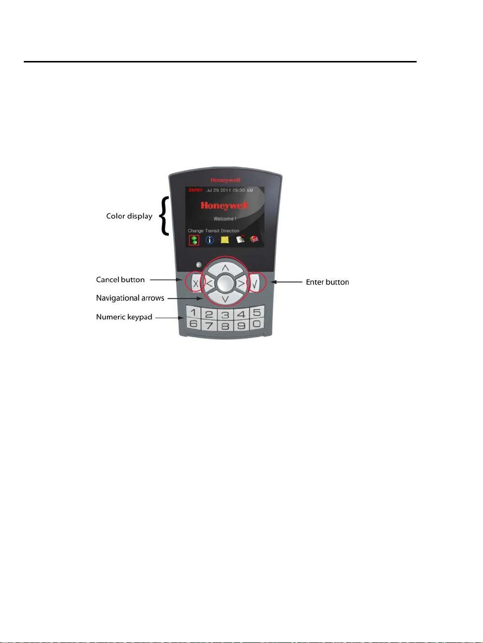
Layout of the device
The Voyager device is an interactive terminal with a graphic display and a reader.
You can use the device for T&A, SAP, canteen management, and access control.
Figure 1 Voyager Compact Device
To perform these functions, the device comprises the following features:
• A color graphic display
• A 10-digit keypad with backlighting
• Backlit navigational arrows and Enter and Cancel buttons
• A speaker
6 https://extranet.honeywell.com
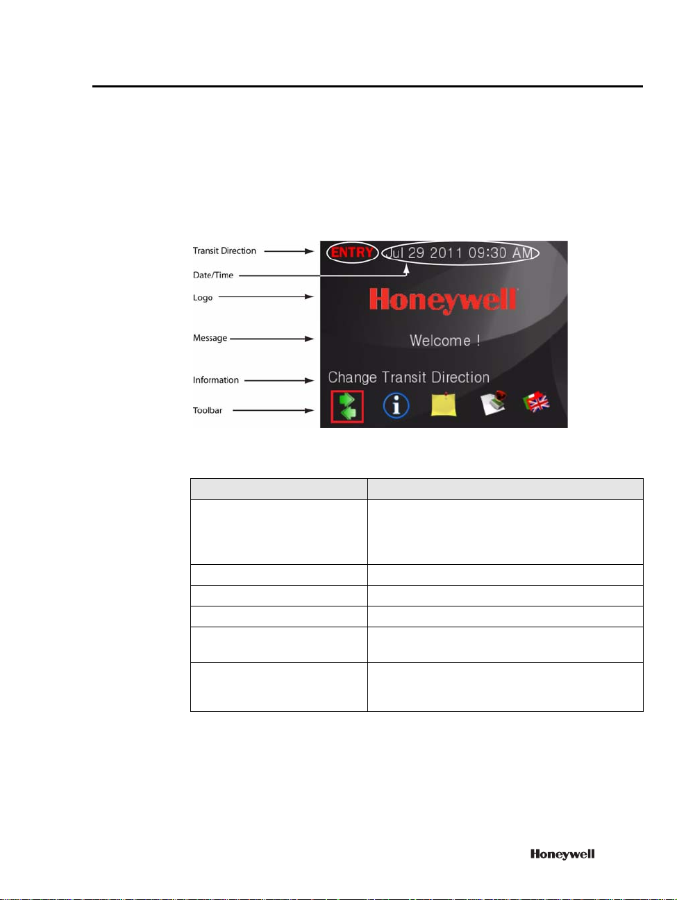
General layout of the display
Figure 2 illustrates the general layout of the Voyager Compact Device display in
idle mode.
Figure 2 Voyager Compact Device display
GENERAL LAYOUT OF THE DISPLAY
Field Description
Transit direction Specifies the direction assigned to the transit
performed. Transit direction is present only for T&A
devices if the Change Transit Direction feature is
configured for the device.
Date/Time Current date/time
Logo Customer logo
Message Configurable text
Information The meaning of the current icon selected, or other
informational messages
Icon bar Icons representing configurable functions available on
the device. You can configure the functions needed
from the available features.
Device displays all follow this basic design. Depending on the context, the device
may also display device status information or interactive features.
7
2 – GETTING STARTED
Interactive function icons
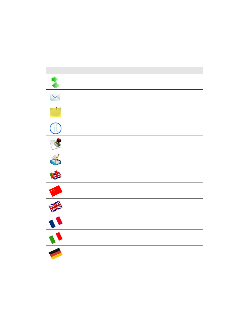
T able 1 lists the standard interactive function icons you may see on the icon bar of
your Voyager device. Icons on the display represent the features enabled for the
device.
Table 1 Voyager system icons
Icon Description
Change Direction—Default icon for the device change direction function
Message—Provides access to the spontaneous message template
Reason—Provides access to the reason template
Enquiry—Provides access to the enquiry template
Transit Category—Pro vides access to the transit category template
ADL—Default icon to access the ADL template
Set language—Default icon for the device set language function
Chinese flag—Indicates Chinese language setting
British flag—Indicates English language setting
French flag—Indicates French language setting
Italian flag—Indicates Italian language setting
German flag—Indicates German language setting
8 https://extranet.honeywell.com
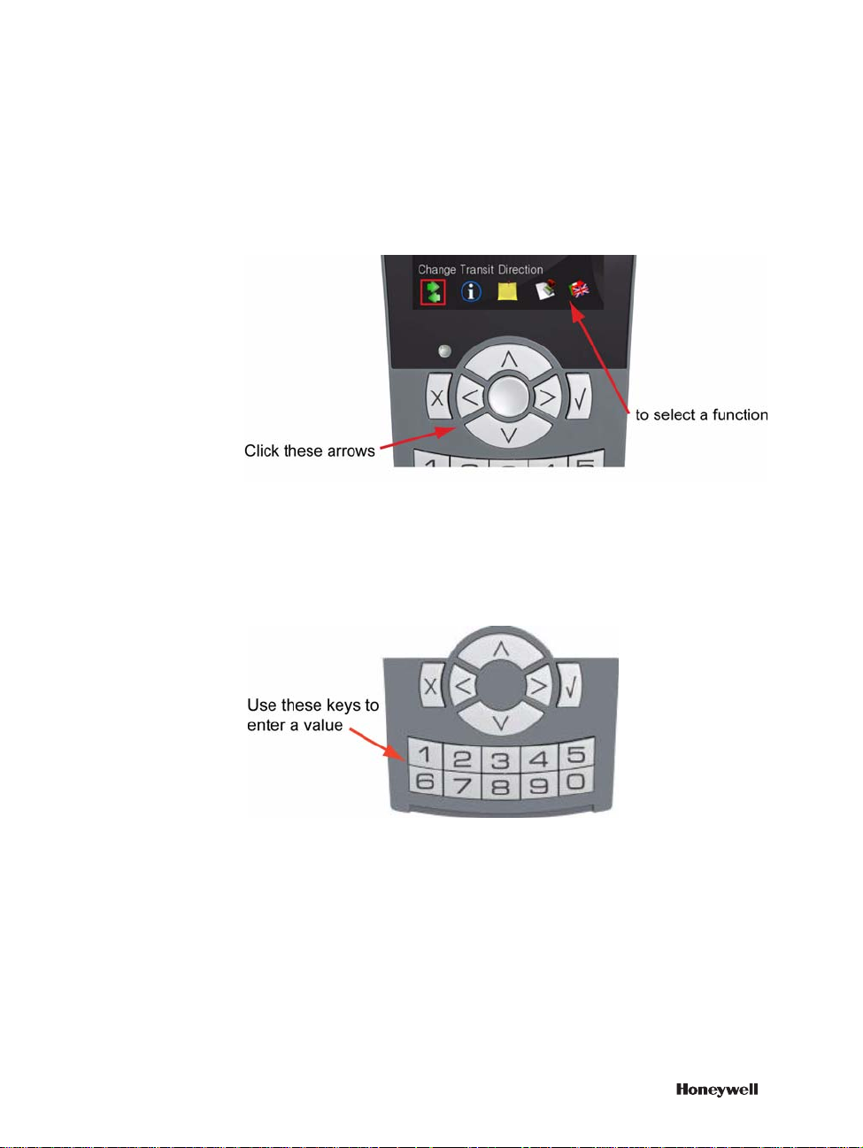
GENERAL LAYOUT OF THE DISPLAY
The currently selected function icon is highlighted with a red square. To
implement a function, use the arrow keys to select an icon and then press Enter.
The new selected icon is then highlighted in a red square.
Figure 3 Voyager Device navigational arrows
To enter a value, such as a PIN, use the numeric keypad.
Figure 4 Voyager Device keypad
For further information on these features, see “Interactive features” on page 19.
9

2 – GETTING STARTED
10 https://extranet.honeywell.com
Understanding device statuses
The Voyager device can generate several device status messages. Status messages
report system modes and unusual occurrences relating to:
• The device
• The door controlled by the device
• Transits
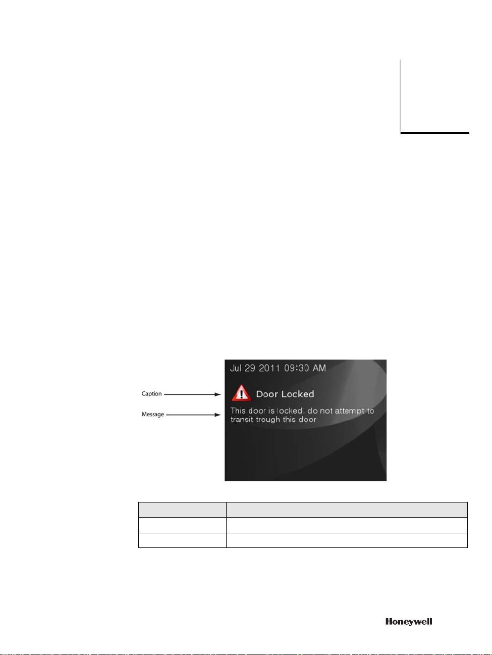
Figure 5 illustrates a generic status display on the device.
Figure 5 Status display
3
Field Description
Caption Name of status
Message Text associated with caption
11
3 – UNDERSTANDING DEVICE STATUSES
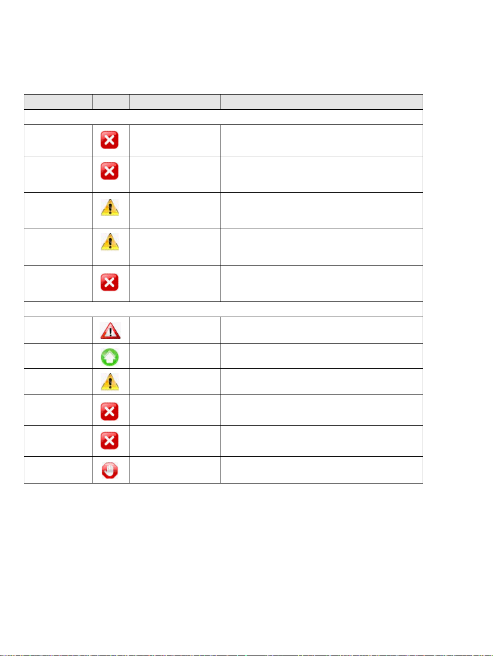
Table 2 Device status messages
Event Symbol Caption Description
Terminal statuses
Terminal not
configured
OUT OF ORDER The reader has not yet been configured. You may not
use the device at this time.
Terminal/Door
out of order
OUT OF ORDER The reader or the door controlled is experiencing
technical difficulties. You may not use the device at
this time.
Terminal in
overdrive mode
DEVICE IN
OVERDRIVEN
This device is set in overdrive mode. You do not need
this device to authorize the transit.
MODALITY
DB Download in
progress
DB DOWNLOAD IN
PROGRESS
The DB download is in progress. You may use the
device but you may experience some delay in response
time.
Transit Buffer
full
TRANSIT BUFFER
FULL
There is no more space available on the device to store
transits. To prevent further loss of transits, this device
has been blocked.
Door statuses
Door locked DOOR LOCKED This door is locked; do not attempt to transit through
this door.
Door unlocked PLEASE ENTER The door is unlocked; proceed with the transit.
Door busy PLEASE WAIT THE
DOOR IS BUSY
A transit is in progress through this door. You may be
unable to transit at this time.
Door forced DOOR FORCED The door managed by this reader has been forced.
Please notify security, then close the door to reset it.
Door not shut
after crossing
DOOR NOT SHUT
AFTER CROSSING
The door should be closed. Close the door to reset it
and notify security.
Transit not
happened
TRANSIT NOT
HAPPENED
For information on transit error messages, see “Error messages” on page 45.
12 https://extranet.honeywell.com
The door has not opened for the transit requested.

Managing transit operations
You can configure your device to perform four types of authentication:
• Card number
• Card number and PIN
•PIN only
• Airport boarding procedure
This chapter describes typical transit operations that use these authentication
methods.
To learn about Go to
Performing a basic transit operation page 14
Performing a transit with a card number and PIN page 17
Clocking in and clocking out page 19
4
For information about PIN only transits and airport boarding, see “Other types of
transit operations” on page 39.
13
4 – MANAGING TRANSIT OPERATIONS
Performing a transit operation with a card
When you present your card to a device for a transit, the device checks the
information stored on your card and then searches in the cardholder archive to
determine your access rights.
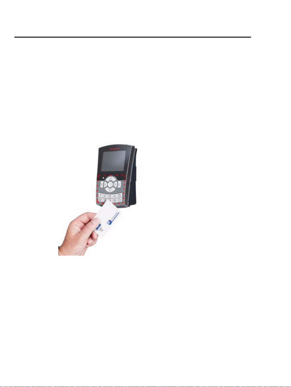
To complete a transit using only a card:
Hold the card a few centimeters from the reader in the highlighted area in
Figure 6. The reader verifies the permissions configured for the card.
Figure 6 Voyager Compact Device
14 https://extranet.honeywell.com

PERFORMING A TRANSIT OPERATION WITH A CARD
When access is granted, the device emits an Access Granted sound (a gentle
chime), displays the Access Granted message, and unlocks the door.
Figure 7 Sample Access Granted display
Field Description
Date Current date
Time Current time
Cardholder info Cardholder peripheral description. cardholder information is
shown only if the device is configured to show it.
Photo Cardholder photo; this option is available only when multimedia
option is installed.
Transit information Transit direction For AC and CA terminals:
ACCESS GRANTED
For T&A or SAP terminal:
CLOCK IN for a transit in Entry direction;
CLOCK OUT for a transit in Exit direction.
For devices that are configured
simultaneously as T&A and AC, the T&A
behavior shall apply.
Time Time of the transit
Reason Reason used for the transit (if any)
Information Indicates the presence of spontaneous messages for the
cardholder. Spontaneous messages are then accessed using the
related function icon/menu and shown using the related template.
Fore more information, see “Reading spontaneous messages” on
page 36.
15

4 – MANAGING TRANSIT OPERATIONS
Field Description
Toolbar Displays icons representing functions configured for the
Once you receive this message, open the controlled door, pass through it, and
close it.
If the transit is denied, the device emits an Access Denied sound and displays an
Access Denied message; the door remains locked.
For more information on error messages, see “Error messages” on page 45.
cardholder who performed the transit.
16 https://extranet.honeywell.com

PERFORMING A TRANSIT WITH CARD AND PIN CODE
Performing a transit with card and PIN code
A card provides identification for the cardholder; a PIN provides authentication.
When a device is configured for both card and PIN verification, it can identify
and authenticate a cardholder.
To perform a transit with card and PIN code:
1 Present your card to the reader. The device identifies your card and performs
the controls on the cardholder archive; if the controls are passed, the device
displays a request for a PIN.
Figure 8 PIN Code request
2 Enter the PIN. The de vice checks the PIN entered against the value stored for
you for the number of retries configured.
Note: You do not need to press Enter to confirm the PIN entered; once the
configured number of digits configured for the PIN is reached, the device
automatically processes it.
When the device verifies that the PIN is correct, access is granted. The device
emits the access granted sound (a gentle chime) and displays the Access Granted
message.
Once you receive this message, open the controlled door, pass through it, and
close it.
If the device doesn’t recognize the PIN value:
• The transit is denied.
• The device emits an access denied sound.
• The device displays an Access Denied message.
• The door remains locked.
17

4 – MANAGING TRANSIT OPERATIONS
If the device is configured for a specific number of retries and that number is
exceeded, the device may also block further use by the cardholder for a specific
length of time.
Signalling a transit under duress
To protect against improper entry, the system includes a way to modify a PIN to
signal a transit under duress.
To signal a transit under duress:
1 Present your card to the reader. The device authenticates your card and then
displays a request for a PIN.
2 FOR ODD NUMBERS: Enter your designated PIN but modify the final digit
to be one LESS than the actual PIN. For example, if the PIN is 5437, enter
5436.
FOR EVEN NUMBERS: Enter your designated PIN but modify the final digit
to be one MORE than the actual PIN. For example, if the PIN is 7938, enter
7939.
3 Wait for confirmation and when you receive it, proceed with the transit.
When the system detects such a signal, the device:
• Grants the transit at the terminal level
• Generates a “Transit under duress” alarm to the Supervision Center
The device does NOT display “Access denied”.
18 https://extranet.honeywell.com

Clocking in and clocking out
In the T&A application, “Clock in” and “clock out” are terms that refer to the
direction of a transit.
Clock in indicates the time you enter the office (the clock starts counting the time
the cardholder is in the office).
Clock out indicates the time you leave the office (the clock stops counting the
time).
A Voyager device can be configured for one direction (clock-in OR clock-out), or
for both directions (clock-in AND clock-out).
In this case, to set a specific direction for the device you must use the “Change
direction” function.
To change the transit direction and perform the transit:
1 Check the current direction set for the terminal that is shown on the right side
of the header of the display.
Figure 9 Change Transit Direction display
CLOCKING IN AND CLOCKING OUT
2 Select the Change direction icon on the toolbar and click Enter. The direction
of the terminal in the header line of the display will change.
3 Present your card to the device.
19

4 – MANAGING TRANSIT OPERATIONS
If the transit is valid, the device emits the access granted sound (a gentle chime),
displays the clock-in/clock-out page, and (if so configured) unlocks the door.
Figure 10 Clock In display
20 https://extranet.honeywell.com

Interactive features
Interactive features are system functions that you can request and display on your
Voyager Device.
To learn about Go to
Changing the display language of the device page 22
Associating a reason to a transit page 25
Associating an Additional Data List (ADL) to a transit page 28
Performing enquiries page 32
Reading spontaneous messages page 35
Working with transit categories page 37
By default you may configure a Voyager door to manage automati cally a
predefined type of function without the need for a cardholder to select the relative
key(s). You may specify:
• a transit category
• a reason (simple or enhanced)
• a enquiry request
In these cases, the device shows, instead of the idle page, the related feature
pages.
5
21

5 – INTERACTIVE FEATURES
Changing the language of the device
At startup, the device displays information in the language that has been set for
it—that is, the default language. The "Set language" function enables you to
change the current language to another of the available languages.
To change the language of the device from the language function key:
1 On the device display, select the set language function flag you need from the
toolbar.
Figure 11 Change language display
2 Press Enter. The device displays the Change Language display for a few
seconds and then returns to the idle page with the new language set.
Figure 12 Selected language display
22 https://extranet.honeywell.com

CHANGING THE LANGUAGE OF THE DEVICE
To change the language of the device from a language menu:
1 On the device display, select the language menu icon.
Figure 13 Change Language Menu icon
2 Press Enter to display the language menu.
Figure 14 Language menu
23

5 – INTERACTIVE FEATURES
3 Select the language you need and press Enter to view the Language selection
display.
Figure 15 Language selection display
After a few seconds, the device returns to the idle page display showing the
new language that you have set.
24 https://extranet.honeywell.com

ASSOCIATING A REASON WITH A TRA NSIT
Associating a reason with a transit
A reason provides an explanation of a transit that is beyond normal operations.
There are two types of reasons:
• Simple - Characterized by a reason code added to the transit
• Enhanced - Characterized by required parameters and entered using an
Additional Data List
To associate a simple reason with a transit:
1 Us e the arrow keys to select the desired reason icon from the toolbar or
description in the menu.
Figure 16 Reason selection display
25

5 – INTERACTIVE FEATURES
2 Click Enter to confirm the selection and display the Reason template.
Figure 17 Reason display
If you select the wrong reason, click Cancel to cancel the operation.
3 Present your card to authenticate the transit.
The device checks your rights to use the reason; if the reason is not usable the
device displays “Feature not available". If the function is usable, the device
checks the validity of the reason; if the reason is not usable, the device
displays “Feature expired”. The device then checks your rights for the transit
and displays the Transit page, including the reason you selected. The device
also inserts the reason code into the transit record.
Figure 18 Transit display
26 https://extranet.honeywell.com

ASSOCIATING A REASON WITH A TRA NSIT
To associate an enhanced reason with a transit:
1 Use the arrow keys to select the desired enhanced reason icon from the toolba r
or description from the menu and click Enter to confirm the selection and
display the Reason template.
The device then displays the Additional Data List template associated with the
reason.
If you select the wrong reason, click Cancel to cancel the operation.
2 Fill in the ADL fields and present your card to authenticate the transit. (See
“Associating Additional Data Lists with a transit” on page 28 for further
information.)
The device checks your rights to use the reason; if the reason is not usable the
device displays “Feature not available". If the function is usable, the device
checks the validity of the reason; if the reason is not usable, the device displays
“Feature expired”. The device then checks your rights for the transit and inserts
the reason code and the ADL parameters into the transit record.
27

5 – INTERACTIVE FEATURES
Associating Additional Data Lists with a transit
Additional Data Lists (ADLs) are groups of parameters you can enter that will be
associated to your transit.
To associate an ADL with a transit:
1 Use the arrow keys to select the desired ADL icon in the toolbar.
Figure 19 Additional Data List template
2 Click Enter to confirm th e selection and display the Additional Data List
template.
Figure 20 Example: ADL for External Wages
If you select the wrong ADL, press Cancel to cancel the operation.
28 https://extranet.honeywell.com

ASSOCIATING ADDITIONAL DATA LISTS WITH A TRANSIT
3 The template presents a list of fields to be filled out. (Mandatory fields are
identified with an asterisk and must be filled in so that the data can be
entered.) Once an ADL is displayed, the cursor is positioned on its first field.
Use the up and down arrows to move across fields; the selected field is
highlighted with a red border.
Table 3 lists each type of field and describes how to use it.
Table 3 ADL configuration fields
Field type Field name display Procedure
Alphanumeric When you select an alphanumeric
field, the device displays a virtual
alphanumeric keyboard. Press
Enter to open the virtual keyboard
on the screen.
Use the arrows to select a key, then
press Enter to confirm the
selection. Proceed in this way for
every character you need to enter.
When you have finished composing
the entry, press on the
virtual alphanumeric keyboard,
then press Enter to insert the value
into the ADL.
Press Cancel to exit from the
virtual keyboard without saving the
input.
To delete a character to the left of
the cursor, press and then
press Enter.
Numeric For numeric fields, use the keys of
the device numeric keypad on the
device (see Figure 1) to fill the
field, then press Enter to confirm.
29

5 – INTERACTIVE FEATURES
Table 3 ADL configuration fields
Field type Field name display Procedure
Date Press Enter to open the calendar
Time There are two options for entering a
List Press Enter to open the list:
display.
Use the arrows to select a day and
press Enter to confirm the
selection.
time:
• Type the desired time (hours and
minutes) and press Enter to
confirm, OR
•a) Press Enter to select the hour
subfield and use the up/down
arrows to increase/decrease the
value, or directly type the
desired hour.
b) Use the right arrow to select
the minute subfield and use the
up/down arrows to increase/
decrease the value, or directly
type the desired minutes.
c) Press Enter to confirm the
value.
4 When you have completed the required fields, present your card to submit the
data and to authenticate the transit.
In case of errors in the data entered (validation or mandatory field missed), the
device displays a specific message and highlights the error field with a red
border.
30 https://extranet.honeywell.com
Use the up/down arrows to select
the item you need and press Enter
to confirm.

ASSOCIATING ADDITIONAL DATA LISTS WITH A TRANSIT
The device checks your rights to use the ADL; if the function is not usable it
displays “Feature not available". If the function is usable, the device checks your
rights for the transit and inserts the ADL data into the transit record.
31

5 – INTERACTIVE FEATURES
Performing enquiries
Enquiries are requests for cardholder information stored in the system that can be
shown on the device display.
The following types of enquiries are available:
• Local and remote transit enquiries
• Local and remote generic enquiries
The procedure for making an enquiry is basically the same for both local and
remote enquiries.
To make an enquiry:
1 Use the arrow keys of the navigator to select the desired Enquiry icon and
click Enter to confirm the selection.
Figure 21 Enquiry display
2 Submit your card to the reader to authenticate the request.
The device checks your permission to make the enquiry . If the function is not
usable, the device displays "Feature not available".
When the request is authenticated, the device displays the information requested.
Scroll between the enquiry lines using the up and down arrows; for Enquiries
with multiple pages, navigate across pages using the left and right arrows. Click
Cancel to exit from the enquiry.
32 https://extranet.honeywell.com

Local transit enquiries
Local transit information is stored on the device itself. You cannot specify the
number of transits that will be shown in the history; that number depends on the
transit activity performed by cardholders who use the device.
Figure 22 Local transit information
Remote transit enquiries
PERFORMING ENQUIRIES
Remote transit enquiries generate a list of all the transits performed by the
cardholder on all the Temaline devices in the system (History of transits). The
information is stored at the Supervision Center.
When you generate a remote transit enquiry, the device submits the request to the
Supervision Center and displays "Waiting for supervision reply" until a reply is
received.
Figure 23 Remote transit information
33

5 – INTERACTIVE FEATURES
If your request times out before the device receives the information, the device
displays "Supervision reply not received" and terminates the operation.
Local generic enquiries
Local generic information is imported from the Supervision Center and sent to the
peripheral device that stores it.
Figure 24 Generic enquiry display
Remote generic enquiries
Remote generic information is imported from external data sources and is stored
at the Supervision Center. See Figure 24.
When you generate a remote generic enquiry, the device submits the request to
the Supervision Center and displays "Waiting for supervision reply" until a reply
is received. Upon authentication, the Supervision Center sends the data to the
device and the device displays it.If your request times out before the device
receives the information, the device displays "Supervision reply not received" and
terminates the operation.
34 https://extranet.honeywell.com

READING SPONTANEOUS MESSAGES
Reading spontaneous messages
A spontaneous message is a short message that is personalized and displayed
whenever a transit occurs—for example, “Please get in touch with Human
Resources office.” When you present your card, the device authenticates you and
if your card is configured for a spontaneous message or if the terminal is
configured to show a spontaneous message, it appears on your device transit
display.
To read a spontaneous message, click on the related icon shown on the transit
page when a transit is performed.
Figure 25 Spontaneous message display
Spontaneous messages can be associated with:
• A specific employee (or to a set of employees) and so addressed exclusively to
the person in question (or the set of people)
• A primary object and so they can be viewed by all authorized users who
transit at the device.
Each Spontaneous Message may include some parameters that put some
condition on the presentation of the spontaneous message, for example:
• A commencement date and an expiry date (message is shown only between
these two dates)
• A direction of the transit (message is shown only for the transit directions
specified)
• A type of transit (message shown only during specific transits, for example
only when a transit is granted)
35

5 – INTERACTIVE FEATURES
Spontaneous messages may also be displayed in different languages. If the device
language is set to Italian, the message is in Italian; if the device language is set to
French, the message is in French.
36 https://extranet.honeywell.com

Working with transit categories
Transit categories are groupings of functions for specific purposes. For example,
a "canteen management" category might group together reasons and ADLs that
relate to canteen management, or an "intrusion" category, allowing the use of
transit reasons with specific feedback, and so forth.
A Transit Category can be associated directly to an icon of the toolbar or to a
menu item.
A Transit Category can be segregated using Authorized Functions.
To use the Transit Category feature:
1 Us e the arrow keys to select the desired T r ansit Category icon and click Enter
to confirm the selection and display the Transit Category template with the
related features.
Figure 26 Transit Category display
WORKING WITH TRANSIT CATEGORIES
If you select the wrong Transit Category, click Cancel or use a specific icon or
menu item to cancel the operation.
2 Us e the features available on the transit category display and then present your
card to authenticate the request.
The device checks your right to use the Transit Category; if the function is not
usable, the device refuses the transit and displays "Feature not available". If the
function is usable, the device checks the validity of the category . If the category is
not usable, the device displays “Feature expired”. The device then checks your
rights to the transit and inserts the generic category label into the transit record.
Finally, the device displays appropriate feedback.
37

5 – INTERACTIVE FEATURES
38 https://extranet.honeywell.com

Other types of transit
operations
This chapter describes some specific transit operations.
To learn about Go to
Performing a transit in semiautomatic mode page 40
Performing a transit with PIN code only page 41
Performing a boarding operation page 43
6
39

6 – OTHER TYPES OF TRANSIT OPERATIONS
Performing a transit in semiautomatic mode
The terminal may be configured to perform a transit in semiautomatic mode.
When you present your card with this configuration prior to the transit, the device
performs all configured controls and sends a transit request to the Supervision
Center. The Supervision Center can grant or deny the transit request.
No range control is performed when the device is in semiautomatic control mode.
To perform a transit in semiautomatic mode:
Present your card to the device. The device checks all the controls; when all the
controls are passed, the device sends a request to the Supervision Center, then
displays the message “Waiting for supervision reply” until you get an answer
from the Supervision Center.
The Supervision Center can accept or deny the transit. If the transit is denied, the
device:
• Refuses the card.
• Displays "Access denied".
If after a certain time there is no reply from the Supervision Center, the device:
• Refuses the card.
• Displays "Supervision reply not received".
40 https://extranet.honeywell.com

PERFORMING A TRANSIT WITH PIN CO DE ONLY
Performing a transit with PIN code only
If the device is set to work in Personal Identification Number (PIN) code only
transit, it authenticates the cardholders using only the PIN code entered on the
display. To use this transit type, every cardholder must be assigned a unique PIN
number.
In this transit mode, the device shows the following display:
Figure 27 PIN code prompt
To perform a transit with PIN code only:
1 Type your PIN code using the keyboard (PIN is always a numeric value).
When you have entered the PIN code, the device use this number to identify the
cardholder and to verify the cardholder’s authorization to transit from the door.
Note: You do not need to press Enter to confirm the PIN entered; once the
configured number of digits configured for the PIN is reached, the device
automatically processes it.
If access is granted, the device emits the Access Granted sound (a gentle chime),
displays the Access Granted page, and unlocks the door controlled by the device.
If the transit is denied, the device emits an access denied sound, displays a wrong
access event, and doesn't unlock the door.
41

6 – OTHER TYPES OF TRANSIT OPERATIONS
If you enter a wrong PIN code the device shows the following alert message:
Figure 28 Wrong PIN code display
Note that if the device has been configured for a specific number of retries and a
block time-out, and you exceed the number of attempts, the device will be
blocked and shows the following display:
Figure 29 Door Locked display
42 https://extranet.honeywell.com

Performing a boarding operation
A device in Airport Boarding mode maintains the door open for a configured
period of time once a cardholder executes the specific boarding procedure.
Figure 30 PIN code prompt
To initiate a boarding operation:
1 On the keyboard, enter the device keyboard code (keyboard code is a numeric
code).
2 Once the code is entered, the device prompts you to present your card.
If the card is authorized, the device unlocks the door for the configured period of
time and shows the following display.
PERFORMING A BOARDING OPER ATION
Figure 31 Autorized Boarding display
43

6 – OTHER TYPES OF TRANSIT OPERATIONS
To terminate a boarding operation:
1 The same cardholder who initiated the procedure must present his/her card
again or (if this option has been configured) another cardholder may present
his/ her card to the device.
The device returns to its Idle display.
Note: When the airport boarding procedure is not in progress, the device accepts
normal transit operations. (See “Performing a transit in semiautomatic mode” on
page 40 for more details.)
44 https://extranet.honeywell.com

Ethernet Connecting and how to configure into EBI system
7. Ethernet connecting and how to configure into EBI system
1. Connect EBI system using Ethernet port.
7
2. Steps to configure Team Voyager
Pre-requsite:
Conform is the MAC address of the devices are unique.
Configure Tema Voyager:
Using EBI server Telnet tools to telnet Team Voyager device.
C:/telent IP
Provide below command to set the device IP and host IP
Vts setip – to configure the Sesamo device IP
Vts sethost – to configure EBI PC IP in the device.
Hon-SH-iMX27 login: root
login[602]: root login on 'ttymxc0'
root@i.MX27# telnet 127.0.0.1
Entering character mode
Escape character is '^]'.
TEMA Virtual Monitor, V2.0 ready (127.0.0.1)
45

Ethernet Connecting and how to configure into EBI system
127.0.0.1>> user Super Visor
Welcome Super (supervisor)
127.0.0.1>> vts setip 159.99.252.199
VTS - Done
127.0.0.1>> vts sethost 159.99.252.240
VTS - Done
127.0.0.1>> vts reboot
VTS Request sent
127.0.0.1>> Calling System reboot
Before providing “>> vts reboot”, set the Jumper #3 to OFF position to avoid
system restore to factory defaults again.
3. Configure Tema Voyager in EBI server:
Connect the Tema Voyager and EBI PC in the network.
Create a new Tema Voyager and configure the device IP in EBI page.
46 https://extranet.honeywell.com

Ethernet Connecting and how to configure into EBI system
Create a new Sesamo door and assign the device. Configure the Gate as
displayed in the attachment.
47

Ethernet Connecting and how to configure into EBI system
Go to Behavior model page and check the newly created door and save.
Once details are downloaded to device verify by showing cards.
Note: Detail information please reference EBI Configure Manual.
48 https://extranet.honeywell.com

8 Device connectors
All the connections are on the back of the reader inside the round area.
Figure 1 Connectors layout
Connector Function Specification
J1 Ethernet interface RJ45 Female Connector
P4 Output interface 5Pin,--3.5MM pitch, Header connector
P5 TAMPER Switch interface 2Pin,--2.5MM Pitch, Header connector
8
Connector Function Specification
P6 RS-485 communication
interface
P7 Inputs and DC power
interface
SW1 RS-485 length settings 2Pin,--1.27MM DIP switches
3Pin,--2.5MM Pitch, Header connector
6Pin,--3.5MM Pitch, Header connector
49

9 Setting inputs, outputs, and jumpers
Digital inputs
The device has 2 inputs and 2 outputs. The 2 inputs can be used either as
digital dry contacts or supervised contacts.
Usually the IN1 is dedicated to the door contact.
Usually the IN2 is dedicated to the push button (request to exit).
However, the inputs can also be used as general purpose inputs.
The typical connection for digital dry contacts is shown in Figure 22.
Figure 22 Dry contacts connections
9
Temaline recommends that you establish an electrical environment where
the cables are well separated, even at short runs, especially to the power
cables or external cables which can be essentially subjected to interference
or lightning.
Use a twisted-pair cable for the contact cables. Make sure that the cables
correspond in size to the norms indicated in “Wire characteristics” on
page 7.
Max contact resistance = 25 Ohm
50 https://extranet.honeywell.com

Supervised inputs
The typical connection for supervised inputs is shown in Figure 23. Put
the resistors close to the contact.
Figure 23 Supervised input connection
Yellow resistor: 1210 Ohm 1%
White resistor: 392 Ohm 1%
Close contact resistance: 296 Ohm
Open contact resistance: 1210 Ohm
Temaline recommends that you establish an electrical environment where
the cables are well separated, even at short runs, especially to the power
cables or external cables which can be essentially subjected to interference
or lightning.
Use a twisted-pair cable for the contact cables. Make sure that the cables
correspond in size to the norms indicated in section INPUT WIRES...
Max contact resistance = 25 Ohm
51

Outputs
Internally, the output lines are provided with Power Mosfet. Using an
external power supply, the output current must not exceed 1.2A/30V
continuous or 5A/30V (0.5 sec) peak current for inductive loads. Using
the internal power supply, the output current must not exceed 30mA.
Usually the OUT1 is dedicated to the Door Electro lock.
Usually the OUT2 is dedicated to the busy lamp.
Outputs can be also used as general purpose outputs.
Temaline recommends that you establish an electrical environment where
the cables are well separated, even at short runs, especially to the power
cables or external cables which can be essentially subjected to interference
or lightning.
External relays powered by the reader
When the load exceeds the max internal current of 30 mA you must use an
external relay.
Figure 24 Relays OUT
52 https://extranet.honeywell.com

: Use 12VDC relay - max coil current = 30mA each. In this case you
Note
must use the 1N4004 diodes shown in Figure 24.
Connecting the door lock directly using an
external power supply
You can connect the door lock directly to the reader using an external
power supply. The current shall not exceed 1,2A or a peak of 5A for a
period of 0,5 sec max.
Figure 25 Connecting loads using an external isolated power supply
: For not-resistive loads:
Notes
• You must use the 1N4004 diodes as shown in Figure 25. Two
diodes are included in the package.
• The external power supply must be isolated.
53

Jumpers
There is a DIP switch (include two bits) in the circle. It is used for
selecting RS-485 matched distance mode.
The Voyager equipment supports biasing and end-of-line termination for
the RS-485 network.
a. RS-485 allows the wiring of a multidrop communication
network of up to 1200 m in length. SW1 DIP switches Pin1,
Pin2 set in ON position.
b. RS-485 Port communication network should not exceed 15
m in length. SW1 DIP switches PIN1, PIN2 set in OFF
position.
Figure 26 Jumpers
Jumper ON/OFF Function
SW1.1&2 ON Long distance - up to 1200m
54 https://extranet.honeywell.com
OFF Short distance - up to 15m

Error messages
This chapter presents tables of possible maintenance, mode, door, and transit
error messages.
Table 4 Maintenance error messages
Status Icon Caption Meaning and Action
Database
download in
progress
Terminal/door
out of order
Terminal not
configured
DB DOWNLOAD IN
PROGRESS
OUT OF ORDER The reader or the door controlled is experiencing
OUT OF ORDER The reader has not yet been configured. You may
The DB download is in progress. Y ou may use the
device but you may experience some delay in
response time.
technical difficulties. You may not use the device
at this time.
not use the device at this time.
10
Transit buffer
full
TRANSIT BUFFER
FULL
There is no more space available on the device to
store transits. To prevent further loss of transits,
this device has been blocked.
55

10 – ERROR MESSAGES
Table 5 Mode error messages
Status Icon Caption Meaning and Action
Overdriven
modality
DEVICE IN
OVERDRIVEN
This device is set in overdrive mode. You do not
need this device to authorize the transit.
MODALITY
Reply not
received
REPLY NOT
RECEIVED
Due to lack of response from the Supervision
Center, the desired operation is cancelled. Retry
the operation, and if the problem persists contact
your system administrator.
Waiting for
reply
WAITING FOR REPLY The desired operation requires data from the
Supervision Center . Please wait for approval
before you continue.
For more information on your site operations,
contact your system administrator.
Table 6 Door error messages
Status Icon Caption Meaning and Action
Door forced DOOR FORCED The door manage d by this reader has been forced.
Please notify security, then close the door to reset
it.
Door locked DOOR LOCKED This door is locked; do not attempt to transit
through this door.
Door not shut
after crossing
56 https://extranet.honeywell.com
DOOR NOT SHUT
AFTER CROSSING
This door should be closed. Close the door to
reset it and notify security.

Table 7 Transit error messages
Status Icon Caption Meaning and Action
Access Denied ACCESS DENIED Access denied. Y ou have violated the access rules
for your site. Contact your system administrator
for further information and assistance.
Card Disabled CARD DISABLED Access denied. Your card is disabled. Contact
your system administrator for further assistance.
Card outside
validity limits
CARD OUTSIDE
VALIDITY LIMITS
Access denied. Your card is not yet valid or has
expired. Contact your system administrator for
further assistance.
Door busy PLEASE WAIT WHILE
THE DOOR IS BUSY
Double transit
request
PLEASE ENTER
ASSOCIATED CARD
A transit is in progress through this door. You
may be unable to transit at this time.
This transit requires an additional card reading to
authorize the access. Enter an associated card
with appropriate rights. Contact your system
administrator for further information and
assistance.
Feature expired FEATURE EXPIRED The feature you selected is not yet valid or has
already expired. Contact your system
administrator for further information and
assistance.
Feature not
available
FEATURE NOT
AVAILAB LE
You are not authorized to use the feature you
selected. Contact your system administrator for
further information and assistance.
Guard Tour GUARD TOUR POINT
ACTIVATION
Incorrect Card
Reading
INCORRECT CARD
READING
This guard tour point has been activated. You can
now proceed to the next step of the guard tour.
The device has detected errors while reading your
card. Retry, and if the problem persists contact
your system administrator.
Invalid
additional data
INV ALID ADDITIONAL
DATA
The additional data you have entered is invalid.
Contact your system administrator for further
information and assistance.
Invalid card INVALID CARD Access denied. Your card is not configured for
this facility; contact your system administrator for
further assistance.
Maximum
number of
cardholders
MAX NUMBER OF
CARDHOLDER IN THE
ZONE
Access denied. The maximum number of
cardholders has been reached in the zone you
have requested access to. Contact your system
administrator for further assistance.
57

10 – ERROR MESSAGES
Table 7 Transit error messages
Status Icon Caption Meaning and Action
Out of time
period
INCOMPATIBLE TIME
PERIOD
Access denied. You are not authorized to transit
through this door on this day at this time. Contact
your system administrator for further assistance.
Passback
violation
PASSBACK
VIOLATION
Access Contact. You have violated the passback
rules. Contact your system administrator for
further information and assistance.
Path control
violation
PATH VIOLATION Access denied. You have violated the path rules.
Contact your system administrator for further
information and assistance.
Security block SECURITY BLOCK Access denied. Contact your system
administrator for further assistance
Selected for
Security
Inspection
SELECTED FOR
SECURITY
INSPECTION
Access denied. You have been selected for
security inspection. Follow instructions from
security personnel.
Threat level RESTRICTED ACCESS Access denied. Access to this zone is temporarily
restricted due to an increase in security threat
level.
Transit not
happened
Wrong Access
level
TRANSIT NOT
HAPPENED
WRONG ACCESS
LEVEL
The door has not opened for the transit requested.
Access denied. You are not authorized to transit
through this door. Contact your system
administrator for further assistance.
Wrong Facility
Code
DOOR LOCKED Access denied. Your card is not configured for
this facility; contact your system administrator for
further assistance.
Wrong PIN
Code
WRONG PIN CODE Access denied. You entered the wrong PIN code.
Contact your system administrator for further
assistance.
58 https://extranet.honeywell.com

Recycling
In accordance with directive 2002/96/EC regarding waste electrical and
electronic apparatus, effective August 13 2005, Honeywell commits,
when requested by the customer, to the collection, treatment, recovery,
and disposal of the apparatus produced.
Customers in the European Union are advised to dispose of this product at
the end of its useful life in accordance with the applicable local laws,
regulations, and procedures.
59
 Loading...