

Page 1
Intruder alarm system
Engineering Information
1 2 3 4 5 6TAPA
/!
Accenta
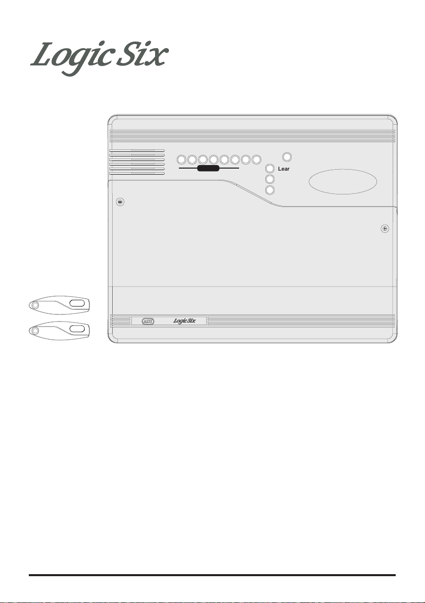
LGSIX/01 Logic Six panel with two pre learnt
Keyfobs
mini
The above intruder system is designed to comply
with the installation requirements of
BS 4737 1986/87.
ZONE
Power
Learn
Error
Day
4188-753 issue 1_1/03 1
Downloaded from: http://www.guardianalarms.net
Page 2

Engineering information
Contents
Features -------------------2
Installation Design --------------3
Fixing the control panel -----------3
Wiring the system --------------4
Tamper network ---------------4
Security zones ----------------5
PA circuit ------------------6
Extension speaker --------------7
External siren Output (Bell box) -------8
13V Supply output --------------9
Set ---------------------9
Factory set condition -------------10
Zone Function ----------------10
First Power up ----------------11
Mains Connection --------------11
Testing the system --------------12
System indications --------------12
Programs ------------------12
Walk tests ------------------13
Alarm tests -----------------13
How to learn new keyfobs ----------14
How to re-learn all keyfobs ----------15
How to learn keyfobs if non are recognised - - 16
Re-arm -------------------17
Alarm Cycle Counter-------------17
Faults --------------------18
Specification-----------------19
Servicing organisation Details --------20
Parts --------------------20
Features
6 Security zones
ÿ
PA input
ÿ
Tamper input
ÿ
Outputs for External siren (Bell) and Strobe
ÿ
Pre-configured Part set program selectable by
ÿ
DIP switch.
Entry Time duration selectable by DIP switch
ÿ
Entry Deviate
ÿ
Alarm Cycle Counter
ÿ
Strobe confirmation on Set
ÿ
Memorises first and subsequent zone
ÿ
intrusions in one alarm period
Walk Test facilities by push button control
ÿ
Alarm Test facilities by push button control
ÿ
Battery capacity of up to 2.1Ah
ÿ
Up to 8 keyfobs can be used with the panel (2
ÿ
Keyfobs supplied pre learnt)
ÿ
Learn mode to learn new keyfobs
ÿ
Erase mode to disable lost or stolen keyfobs
2 4188-753 issue 1_1/03
Page 3
Logic Six intruder system
Installation Design
The purchase of this alarm system represents a
major step forward in the protection of the
property and its occupants. It is important to plan
the installation before proceeding following the
procedures and advice contained in this manual.
Plan the position of each part of
the alarm system and the cable
runs. Detectors should be sited
with particular regard to the
degree of coverage required
and the function of each of the zones.
All of the system wiring is
Power
connected directly to the panel.
The intruder panel must be
installed near an entry/exit
point.
One additional internal sound
speaker is recommended, it
will provide high volume alarm
tones and low volume
entry/exit tones. Speakers
should be positioned to provide good sound
distribution throughout the building and so that
the exit tone is audible outside the main entry /
exit door. This will enable the system operator
to check that the system is setting correctly.
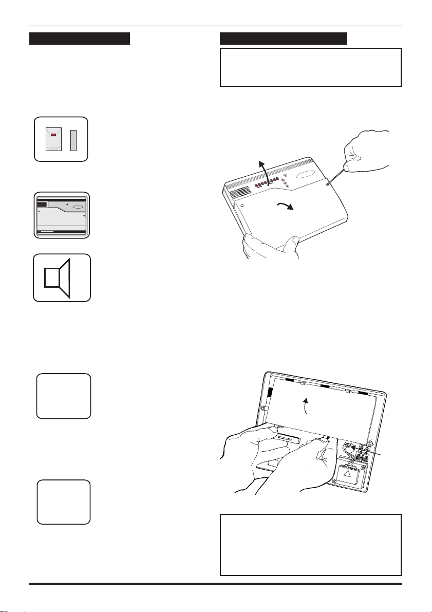
Fixing the control panel
Caution: When positioning the control
panel ensure that it is located in a dry
place away from damp areas.
a. Remove the front cover(s) from the
base assembly.
Power
PA
TA
6
5
Learn
4
3
2
1
Error
ZONES
Day
Disconnect the transformer wires from
the board, these are marked AC.
Carefully remove the board by gently
pushing down the holding clips on the
bottom edge of the board and withdraw
it from the base.
Finally note that the total
current output of this control
I
TOTAL
total current consumption of every part of the
system (in alarm condition) is
1A when supported by a fully
charged battery. Calculate the
system including the panel, external siren with
strobe light (bell box) and detectors to ensure
that this rating is not exceeded.
Depending on which area you
live, you may be required, by
LA
installation. The local authority requirements
may differ from area to area, therefore it is
advisable to contact local environmental officer
to obtain full details of your area requirements.
4188-753 issue 1_1/03 3
law to notify the Local
Authority and Police of the
new security alarm
Note: When replacing the board align it
on the round support pillars to the bottom
and allow it to click down past the clips
at the top of the case. Refit the
transformer wires into the terminal.
Page 4
Engineering information
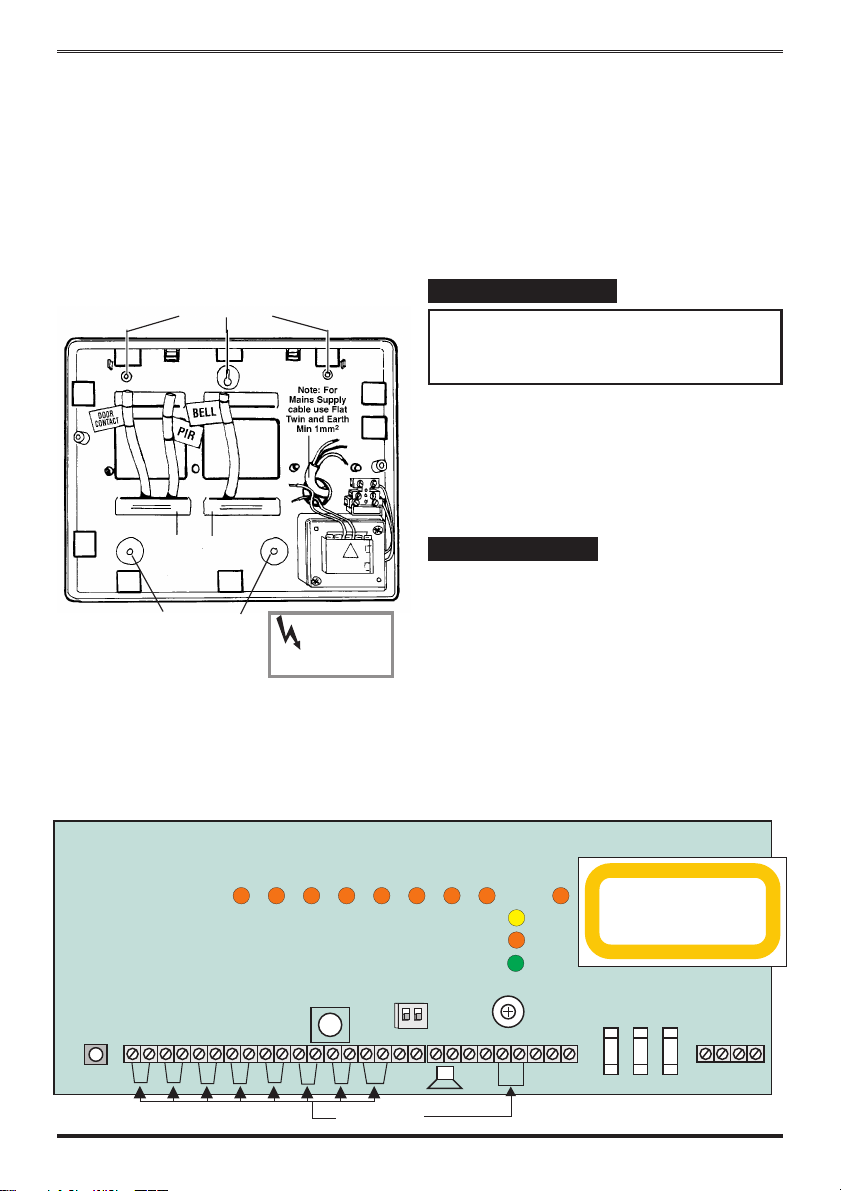
b. Fit the panel to the wall with suitable
fixings. Ensure the wall surface is flat to
prevent base distortion. There are
cable entry holes provided in the rear
of the base and around the outside
edges through the thinned out plastic
sections which may be cut away as
required.
c. The hole provided adjacent to the
mains transformer is a dedicated mains
cable entry point.
Mounting holes
There are three fuses mounted on the circuit
board, all are 20mm quick blow.
F1 1.6A - to protect the +ve line of 12V battery
F3 1A - to protect the Speaker 13V supply
F5 1A - to protect the Siren & Strobe
supply
As supplied, there are wire links are fitted across
the PA and Tamper terminals to represent a
closed circuit.
Wiring the system
Caution: Always power-down the panel
when wiring external circuits, to prevent
damage to the panel electronics.
Systematically wire and test each circuit:
Zones, Tamper and PA circuits
ÿ
Finish by wiring any additional extension
ÿ
speaker sounders, external siren (bell) /
strobe and the 13V supply.
Board
WALK /
ALARM TEST
SW2
Cable entry
holes
Mounting holes
LD2 LD8 LD9 LD4 LD10 LD5 LD11
J1
3
214
High Voltage
~
230V 50Hz 0.2A
FUSE T125mA 250V
(ANTI-SURGE)
LD3
SW1
J2
65
Danger
TAMP
PA
+
Factory fitted links
TAMP
Tamper network
The Tamper circuit is used to protect all cables
and detectors in the system from unauthorised
access including the panel cover.
The zone and PA tampers should be series wired
and connected to the TAMP terminals. The
terminalsT&Aarefortheexternal siren
tamper. Tamper alarms that occur in the Day
mode operate internal sounders only. Tamper
alarms in Set cause a full alarm condition.
Tamper is indicated by the Tamper TA
indicator.
LD6
LD23
LD12
LD22
-
15S
30S
ENTRY TIME
+13V 0V
PART SET
ON
OFF
J6
-
STROBE
VR1
VOLUME
+
TA
SCB
DB
BELL
+
-
SET
+ve
BELL/STROBE
13V / SPEAKER
1A 1A 1.6A
F1F3F5
BATTERY
+BATT
J4
AC
4 4188-753 issue 1_1/03
Page 5
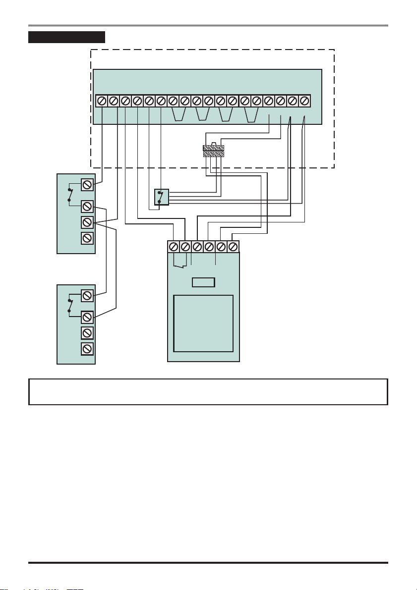
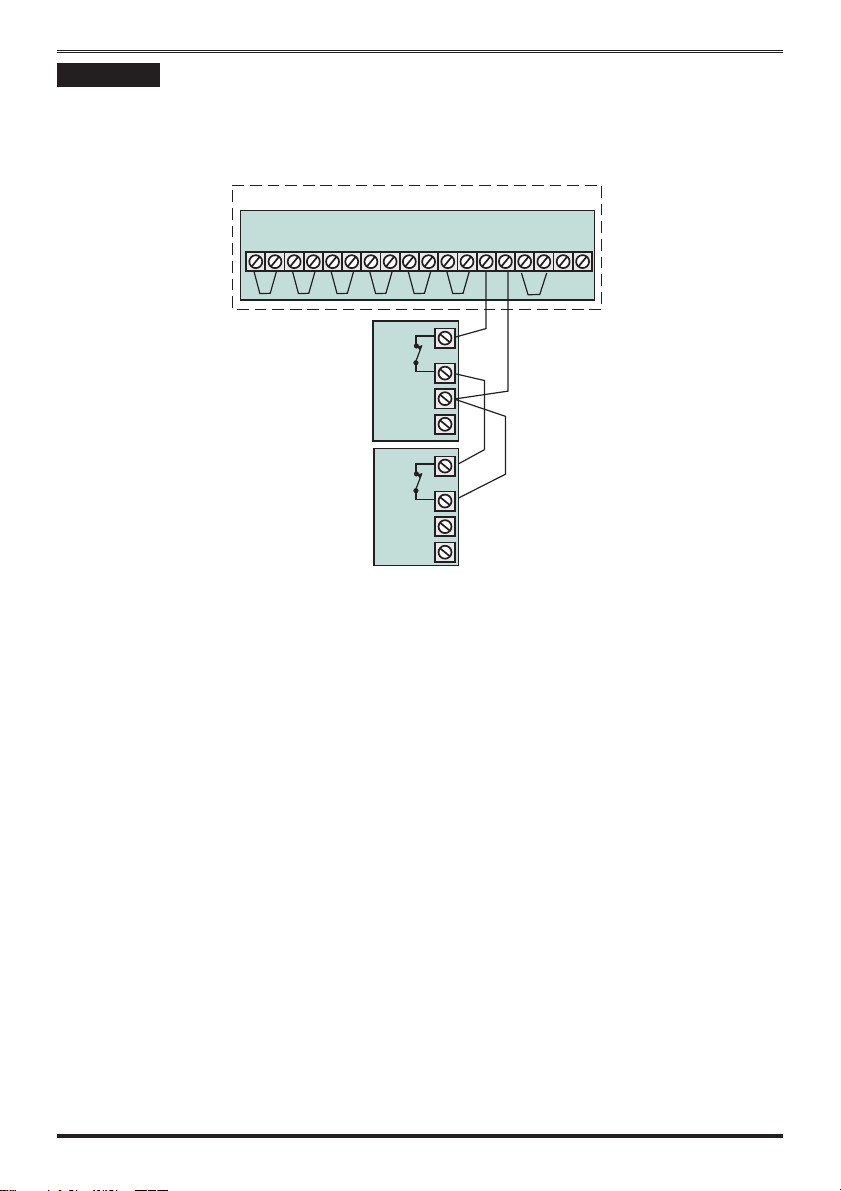
Security zones
J1
Door
Contact
Panel
Board
J2
3
214
65
Terminal block
is not supplied
PIR
+-
Tamp
Alarm
Logic Six intruder system
TAMP
PA
+
-
+13V 0V
All unused zones
must have links fitted
to disable the zone.
Door
Contact
PIR
Note: The panel is supplied with wire links for unused zones. All unused zones must
have links fitted to disable the zone.
It is recommended that no more than 10 magnetic contacts are connected to the same zone.
4188-753 issue 1_1/03 5
Page 6
Engineering information
PA circuit
Any quantity of normally closed type personal attack button may be wired in series and then
connected to the PA circuit.
Operational in Day and Set, the PA circuit will cause a full alarm condition when activated. PA is
indicated on the control panel as PA.
Panel
Board
Panic
Button
Panic
Button
J2
TAM P
PA
65
+
-
+13V 0V
J1
3
214
PA buttons may be fitted near the front door, or in a bedroom.
6 4188-753 issue 1_1/03
Page 7
Logic Six intruder system
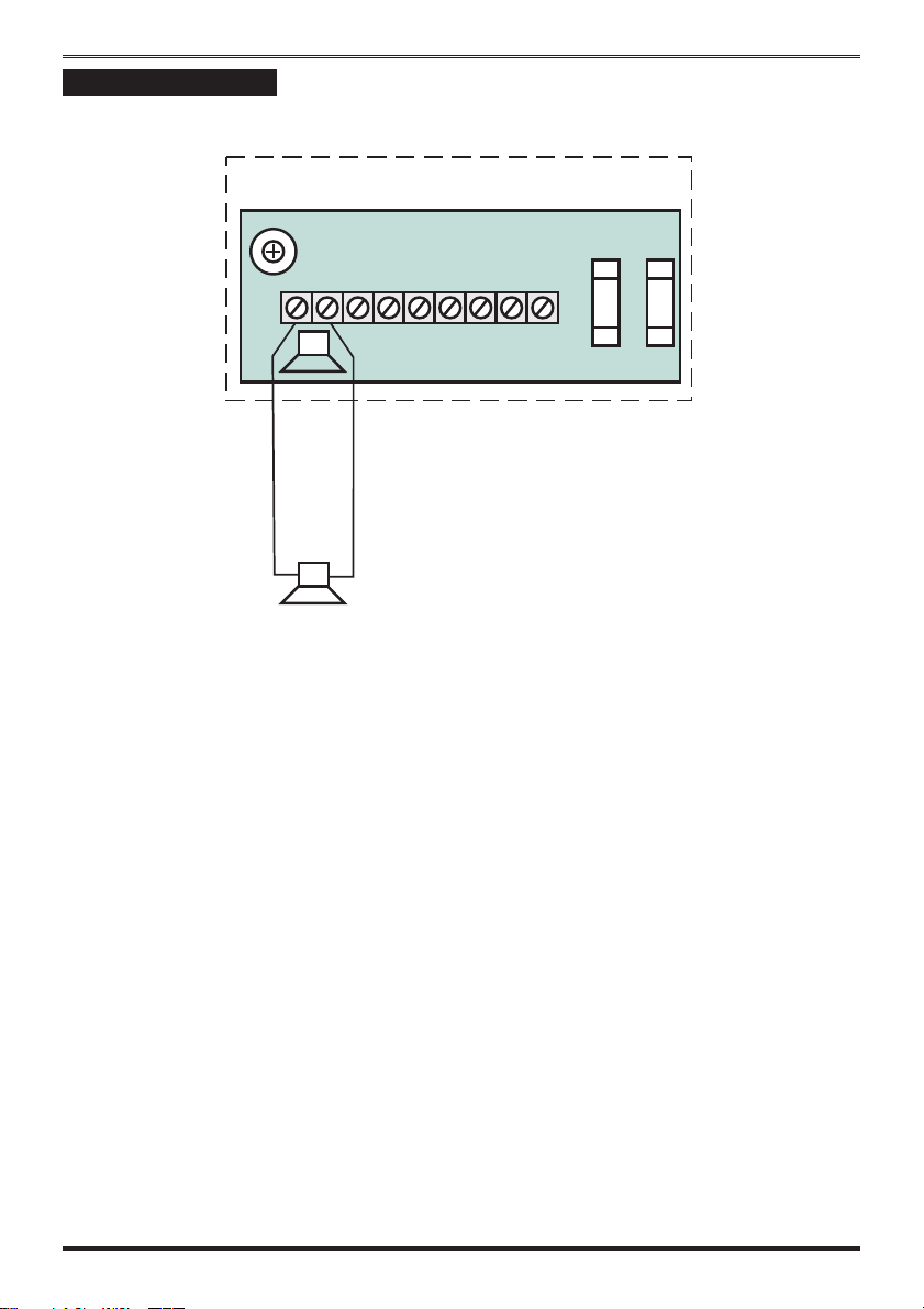
Extension speaker
Extension speaker may be connected to the loudspeaker terminals to produce high volume alarm
tones and low volume entry / exit fault tones.
Panel
VOLUME
VR1
Board
F5
F3
J6
-
+
STROBE
TA
SCB
DB
BELL
-
+
SET
+ve
13V SPEAKER
BELL/STROBE
1A
1A
16 Ohms Extension Speaker
A 16 ohms extension speaker may be wired across the speaker terminals. Mounted in convenient
position within the installation the extension speaker will reproduce all of the alarm tones generated
by the control panel.
A control marked VOLUME in the centre of the board may be used to adjust the low volume
entry/exit tones to suit environmental conditions.
4188-753 issue 1_1/03 7
Page 8
Engineering information
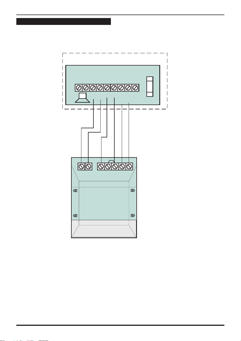
External siren Output (Bell box)
The external siren (bell box) is usually installed in a high position from where the siren could be
seen and heard.
Terminal TADBareforconnecting to the external siren. These terminals provide a
power/hold-off supply, sounder trigger and tamper circuit to protect the external siren housing.
Panel
Board
J6
-
+
TA
STROBE
SCB
+- TEADB
STROBE
DB
BELL
-
+
SET
+ve
F5
BELL/STROBE
1A
Sonade
The terminals are summarised as follows:
T - -Ve tamper return
A - -Ve supply (0V)
D - +Ve supply (12V)
B- -Ve Sounder trigger
For ease of installation, ADE external sirens and modules use the same markings.
Where a discrete external siren is used, it should be connected to terminalsD&B.TerminalsT&A
are then used for tamper protection for the housing.
8 4188-753 issue 1_1/03
Page 9
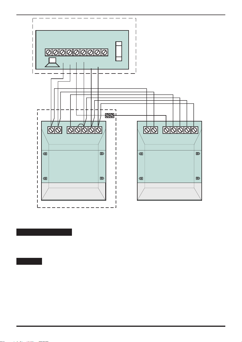
Panel
Logic Six intruder system
Board
J6
-
+
TA
STROBE
SCB
+- TEADB
STROBE
DB
BELL
-
+
SET
+ve
F5
BELL/STROBE
1A
#
# Terminal block
is not supplied
+- TEADB
STROBE
Sonade
Sonade
Where self contained / powered sounders are used, carefully follow the manufacturers instructions,
match each of the terminals to those above.
13V Supply output
The 13V output is to power detectors which require a voltage supply (PIR detectors etc). The supply
is present at all times and may be used to supply a total load of 350mA.
Set +VE
The output , marked SET +VE is used with latching detectors. The output becomes positive on
correct Set of the system and is removed on UNSETTING the system.
4188-753 issue 1_1/03 9
Page 10

Engineering information
Factory set condition
Keyfob 1 and 2 (supplied) - Learnt
Keyfobs 3 to 8 (optional) - - Require learning
External siren Bell Duration 20 minutes
External siren Bell Delay - - No delay
Full Set
Zone1 ---------Timed
Zone 2 ---------Time inhibited
Zone 3, 4,5&6 ----Immediate
Entry time (timed zone)- 30seconds(default)
(15 seconds via setting DIP switch)
Exit mode is timed - - - 30 seconds
Part set (DIP switch selectable see page 12)
Zone 1,2&3 -----Timed
Zone 4 ---------Immediate zone
Zone5&6-------Omitted zones
Entry time (timed zone)- 30seconds(default)
(15 seconds via setting DIP switch)
Silent Exit mode is timed 30 seconds
Applicable for both full and part set:
Tamper TA 24 hour alarm
Personal Attack PA 24 hour alarm
Security Zones -------Zones 1…6
Zone debounce period - - - 640mS ALL zones
Zone Function
The following are definitions of zone functions:
Timed : This function would be used to protect
the main entry/exit door of the entry route.
Time inhibited (Walk through) : This is a zone
which, on setting the panel, allows access to the
Entry / Exit zone. However, if the panel is set
and an time inhibited zone is triggered before an
Entry /Exit zone then an alarm will be generated
immediately.
Immediate: This is a zone which will, when
entered, go into alarm when the panel is set.
The Entry deviate feature permits an immediate
zone to be activated during the entry period
without causing a full alarm.
Unused : An unused zone that has been linked
out will be ignored by the panel.
10 4188-753 issue 1_1/03
Page 11

Logic Six intruder system
TA
First Power up
Before power up fit the top cover on to the base
and connect the speaker wires. Leave the cover
in position throughout the reset of the
installation.
a.
Check that the factory fitted links are
connected to terminals unused Zones,
PA, TAMP and T-A.
b. Fit the battery wires to the BATT
terminals on the Board, Red to + and
Black to -.
Black -
F1
BATTERY
1.6A
(red)
+
Panel
12V battery
c. On connecting the battery the system
will now go into alarm condition, the
Tamper LED is lit and the Power LED
gives a flashing indication:
d. Fit the cover to hold down the tamper
spring at the bottom centre of the
board.
e.
Offer a keyfob to the centre depression
on the panel. Note the Tamper LED
and Alarm switches Off and the
Day
LED is lit.
Power
1 2 3 4 5 6TAPA
ZONE
Learn
Error
Day
/!
Accenta
mini
Offer keyfob
to the Panel
and withdraw
Board
J4
+-
AC
BATT
N
E
L
125mA Fuse
Transformer
Power
Alarm
Keyfob recognition beep
Note: If you do not withdraw the keyfob
after it is recognised by the panel then
you run the risk of entering an undesired
mode of operation.
Mains Connection
The mains power should be connected using a
3 core cable of not less than 0.75mm sq. from a
fused spur to the mains connector inside the
control panel. The 2 A fused spur must be
located close to the control panel.
Dedicated mains supply
from consumer unit.
2A Fused Spur unit
Panel
12V battery
Note: The mains supply must be
connected by a technically competent
person and according to current IEE
regulations.
Caution: To avoid the risk of electrical
shock you must always totally isolate the
mains supply before opening the control
panel cover(s).
ÿ
Mains Input Fuse rating: 125mA, 250V type
T (anti surge) and of a type approved to IEC
127 part 2 sheet III.
On connecting the mains supply to the panel the
power indicator is lit.
Power
Black -
F1
BATTERY
1.6A
(red)
+
+BATT
Transformer
Board
J4
AC
125mA Fuse
(Changes from flashing to steady)
N
E
L
4188-753 issue 1_1/03 11
Page 12

Engineering information
r
r
Testing the system
Complete the wiring of the system and then:
Program the panel.
ÿ
Fully test the system and ensure it is fault
ÿ
free
Fill in the installation log at the back of this
ÿ
manual and retain if for future reference.
Finally explain the operation of the system
ÿ
to the end user. The Operating Instructions
are attached to the centre of this manual.
Detach them and leave them with the
user.
Key
LED steady On indication
LED flashing indication
LED Off
Internal sound
Sound description
NOTE: In general a flat beep is
an indication of not recognised keyfobs.
Programs
The panel offers Full Set or selectable Part Set
routine and programmable entry time. As default
the panel is set for Full Set and an Entry time of
30 seconds.
Full Set : Arms all of the zones and become
ÿ
Set as the user leaves the property after the
Exit time of 30 seconds.
Part Set : To protect the downstairs areas of
ÿ
the house at night the Zones 5 and 6 are
omitted from being set as the user goes
upstairs after the Exit time of 30 seconds.
Panel
Board
ENTRY TIME
15S
30S
PART SET
J6
ON
OFF
External devices
Strobe
Note: The Part Set assumes Zone 5
and Zone 6 are upstairs zones.
External Siren
ÿ
Entry time 30 seconds (factory default):
Allows the user to enter the premises and
unset the system within 30 seconds.
System indications
Day
Powe
- Unset system indication
Powe
- Set system indication
ÿ
Entry time 15 seconds : Allows the user to
enter the premises and unset the system
within 15 seconds.
Note: The Power LED will give a
flashing indication when there is a mains
supply failure to the panel.
12 4188-753 issue 1_1/03
Page 13

Logic Six intruder system
Walk tests
The walk test function allows each detector to be
checked in order to verify that they are
functioning correctly.
To enter walk test the panel must be in Day
mode with the DAY LED lit:
a. Open the bottom cover of the panel.
Note this will cause a tamper alarm.
b. Present a recognised keyfob and the
alarm sound stops. Tamper TA
LED will flash to give a tamper
indication.
c. Momentarily press the PCB mounted
push button. Note do not hold the
button down or it will go into Walk test.
Panel
Board
WALK /
ALARM TEST
SW2
The DAY LED starts to flash.
d. Upon activation of any zone, the
relevant ZONE led will latch up and
a“Zone fault” tone is emitted.
e. Pressing the push button again at any
time will clear the latched LED and
walk test is restarted.
f. On completion of Walk Test, close the
panel cover and an “OK” tone is
emitted and the panel returns to Day
mode with the Day LED lit.
Alarm tests
The alarm test function allows you to test the
Strobe, Siren (Bell), Low and High volume
sounders of the system, SET+ output.
The Alarm Test mode could also be
activated while in Walk Test mode, if
you are doing this go straight to step d).
To enter Walk Test mode the panel must be in
Day mode with the DAY LED lit:
a. Ensure the bottom cover of the panel is
open. Note this will cause a tamper
alarm.
b. Present a recognised keyfob and the
alarm sound stops. Tamper TA
LED will flash to give a tamper
indication.
d. Press the PCB mounted push button
and hold for 3 seconds.
Panel
Board
WALK /
ALARM TEST
SW2
e. The tests below are performed
consecutively. Automatic advance to
the next test after 3 seconds.
1) Low Volume Sounders
2) High Volume Sounders and Strobe
3) External Bell and Strobe
4) SET+ output and Strobe
f. On completion of Alarm Test an “OK”
tone is emitted and the panel returns to
Day mode with the DAY LED lit.
Close the bottom cover of the panel
and the Tamper TA LED switches Off.
4188-753 issue 1_1/03 13
Page 14

Engineering information
,
How to learn new keyfobs
Using a recognised the can learn further keyfobs. A total of 8 keyfobs are recognised
learnt keyfob panel
by a Panel. You may want to do this if you have acquired additional keyfobs. Using these procedures
the panel will still memorise previously learnt keyfobs. New k
Power
Day
Ensure the is in the day mode with the LED lit. You should
have one and the new keyfobs available.
panel
learnt keyfob
When an unrecognised keyfob is offered to the it will cause the
LED to be lit and a continuous sound is emitted from the
Error
eyfobs must be learnt by the .panel
Day
panel
local sounder.
Hold for
10 seconds
1
Indication given assumes
2 keyfobs were previously
learnt by the Panel
Panel
Learnt
keyfob
keyfob recognised beep
x 5 rapid beeps
32
Panel
New
keyfob
keyfob recognised beep
Learn
Learn
Hold the
recognised such that it touches the centre
‘learnt’ keyfob
depression on the Panel and keep it there without movement for
10 seconds.
10 seconds
You are now in the The LED will give a flashing
indication and the LEDs change from flashing to steady On
indication to show recognised or . The is now
ready to learn signalled by the next
flashing LED. Withdraw the keyfob.
In the when an already learnt keyfob is offered to the
You will hear a keyfob recognition beep and
later five rapid beeps from the local sounder.
learn mode. Learn
ZONE
learnt keyfob Panel
new keyfobs
ZONE
learn mode
an Error indication will be given.
The will timeout after 10 seconds if no action is taken to
learn mode
learn new keyfob
Offer a slightly touch it on the centre depression of
new keyfob
the A learnt indication is given of the when the
Panel. new keyfob
flashing LED changes to steady On indication and there
ZONE
is a recognition beep given by the local sounder.
Shortly after the next numbered LED will start flashing.
ZONE
Withdraw the learnt keyfob.
You now have up to 10 seconds to learn another new keyfob.
Panel
1 42 3
For keyfobs 7 and 8 the indications are TA and PA LEDs
respectively.
x 2 beeps
Power
Day
Repeat to learn the
Once all the keyfobs are recognised ‘learnt’ by the wait for
just over 10 seconds for the Panel to exit the this is
new keyfob.
Panel
learn mode,
announced by two beeps from the local sounder
and return to mode indication.
Day
14 4188-753 issue 1_1/03
Page 15

How to re-learn all keyfobs
.
Logic Six intruder system
Using a recognised the can re-learn up to 8 keyfobs. You may want to do this after
a keyfob is lost or stolen and you want to prevent the use of it to operate the system.
learnt keyfob Panel
Keyfobs must
be learnt by each installed in a systemPanel
By entering the in this manner you will erase all
learn mode
recognition of previously learnt keyfobs at the Panel, except for the
Power
Day
one used to enter the .
Ensure the is in the day mode with the LED lit. You must
have one and up to 7 further keyfobs to be learnt. Have
Panel
learnt keyfob
learn mode
Day
all the keyfobs available.
Hold for
20 seconds
Panel
When an unrecognised keyfob is offered to the it will cause
the LED to be lit and continuous sound to be
Error
Panel
emitted from the local sounder.
Learnt
keyfob
keyfob recognised beep
Learn
1 2 3
x 5 rapid beeps
Learn
1 2
Hold the
recognised slighty touching the centre
depression on the and keep it there without movement
for . Initially you will hear a keyfob recognition beep and
20 seconds
10 seconds
another you will hear 5 rapid beep tone from the local
10 seconds
sounder. You are now in the The LED will give a
flashing indication and the LED changes from flashing to
steady On indication to recognise the .
The is now ready to learn the , signalled by the
Panel next keyfob
LED flashing. Withdraw the learnt keyfob.
ZONE 2
In the when an already learnt keyfob is offered to the
learn mode
an Error indication will be given.
Panel,
The will timeout after if no actions is taken
learn mode 10 seconds
‘learnt’ keyfob
Panel
later five rapid beeps from the local sounder. After
learn mode. Learn
ZONE 1
learnt keyfob
to learn the next keyfob
x 5 rapid beeps
Panel
Offer the slightly touch it on the centre depression of the
A learnt indication is given of the when the flashing
next keyfob Panel
next keyfob ZONE
LED changes to steady On indication and there is a recognition
Next
keyfob
keyfob recognised beep
beep given by the local sounder. Shortly after the next numbered
indicator will start flashing. Withdraw the learnt keyfob.
You now have up to 10 seconds to start learning another keyfob.
ZONE
Learn
1 2 3
x 2 beeps
Power
Day
4188-753 issue 1_1/03 15
Repeat to learn the
Once all the keyfobs are recognised ‘learnt’ by the wait for just over
10 seconds for the Panel to exit the this is announced by two
beeps from the local sounder and return to mode indication.
next keyfob.
Panel
learn mode,
Day
Page 16

Engineering information
How to learn keyfobs if none are recognised
You will only need to learn keyfobs in this manner if no keyfobs are recognised by the
learn up to 8 keyfobs following power up of the intruder system.
learnt available. Keyfobs can be learnt by each installed in a system
J6
-
+
DB
TA
1
ZONE
STROBE
SET
BELL
SCB
-
+
Panel
Ensure the is connected to the intruder system and the
link is fitted on the
Power up the intruder system you will hear five rapid beeps to
acknowledge the is in the .
You must have all the keyfobs to be
Panel
Panel PCB between Z1 and Set.
Panel Learn mode
Panel.
A can
Panel
POWER UP THE SYSTEM
x 5 rapid beeps
Learn
1
Panel
Hold
first
keyfob
keyfob recognised beep
Learn
1 2
Panel
Next
keyfob recognised beep
keyfob
Learn
1
2 3
The will NOT timeout until the first keyfob is learnt.learn mode
Hold the slightly touching it on the centre depression
first keyfob
of the .
the LED changes from flashing to steady and there is
ZONE 1
Once the is acknowledged by the
Panel
first keyfob Panel
a recognition beep given by the local sounder. Withdraw the learnt
keyfob. The is now ready to learn the ,
signalled by LED flashing.
Offer the slightly touching it on the centre depression
of the A learnt indication is given of the when
the flashing LED changes to steady On indication
Panel next keyfob
ZONE 2
next keyfob
Panel. next keyfob
ZONE
and there is a recognition beep given by the local sounder.
Shortly after the next numbered LED starts flashing.
ZONE
Withdraw the learnt keyfob.
You now have up to to learn the10 seconds next keyfob.
x 2 beeps
Power
Day
Repeat to learn the next keyfob.
Once all the keyfobs are recognised ‘learnt’ by the Panel wait
for just over and the Panel will exit the10 seconds learn mode,
this is announced by two beeps from the local sounder and return
to Day mode indication.
Now remove the link between Z1 and Set.
16 4188-753 issue 1_1/03
Page 17

Logic Six intruder system
NVM Error
A Non Volatile Memory NVM error indication
is given by a flashing Error LED. If an NVM
error occurs then you will need to re-learn all the
keyfobs, see page 16.
Re-arm
After an alarm the panel will automatically reset
itself when the external siren (bell box) 20
minute timer has expired.
Alarm Cycle Counter
An alarm cycle is considered as the duration of
an alarm from trigger to the end of 20 minutes
operation of the external siren. The panel allows
three alarm cycles during either set or unset
period. When the third alarm cycle expires the
panel is shut down, the storobe continues to
operate. The panel is unset in the normal way
see operating instructions.
4188-753 issue 1_1/03 17
Page 18

Engineering information
Faults
Fault conditions are often the result of minor
installation errors or misinterpretation of the
equipment being installed. The following points
outline the most common installation and
commissioning faults.
a.
If a tamper TA or Personal Attack PA
fault is present on the system, a
flashing indication is given of first fault,
it will go to a lock out condition
(showing the appropriate indication).
Rectify the fault and offer the keyfob to
the panel to remove the fault.
b. The most common cause of a zone not
responding to detection is incorrect
wiring. Normally closed detectors must
be wired together in a series loop
before connecting into the appropriate
ZONE terminals. Tampers are series
wired in the same manner.
c. Where a permanent zone fault is
showing and the loop resistance is
found to be in order, the most probable
cause is a short circuit between the
zone wiring and the tamper wiring.
When measured with a multimeter the
series resistance between the zone
and tamper wiring should be infinitely
high.
removing the control panel covers.
Where normally open and closed
detectors are being used these must
be wired to a zone in the manner
shown.
The example below shows how to wire
normally open detectors on zones 3.
Panel
Board
J1
3
214
Normally open
detectors
J2
TAMP
PA
65
+13V 0V
-
+
The example below shows how to wire normally
open detector on zones 3 and a normally closed
detector on zone 4.
Panel
Board
J1
214
J2
TAMP
PA
3
65
+13V 0V
-
+
Normally closed
detector
d. If totally lost as to the cause of a fault,
remove ALL wiring from the Board.
Refit the 9-links and test the system.
Never fit links to any positions other
than those marked on the Board.
e. Before testing or replacing any fuses,
ALL power must be removed. Fuses
which fail continually are almost
certainly the result of a short circuit or
low resistance across the 13V supply
f. Where Pressure mats are being used
these must be connected to a zone in
the manner shown. The example below
shows pressure mats connected to
zones 3.
Panel
Normally open
detectors
Board
J1
3
214
J2
TAMP
PA
65
+13V 0V
-
+
or external siren (bell box) supply
(terminal D).
Whenever working close to the mains
supply or connector, you should
Pressure Mats
exercise extreme caution always
isolate the mains supply before
18 4188-753 issue 1_1/03
Page 19

Specification
Indicators on
Control panel
6 Zones +ve loop, Security zones
Tamper -ve loop, always active
PA +ve loop, always active
User keyfobs Up to 8 keyfobs can be
Keyfob operating
range
Proximity reader 125KHz inductive
External siren
(Bell box) Output
Strobe Output 12V latching
Extension Speaker
Exit time 30 seconds
Entry time Programmable by DIP
Full/Part Set Programmable by DIP
Walk and Alarm
Tests
Zone Input Delay 640mS
Set +ve Output 0V in Day (sinking
Current
Consumption
Control panel
Low voltage
output
Rechargeable
Battery
Charge Voltage 13.8V dc (+/-5%)
Board Fuses 1.6A & 1A 20mm quick
Mains Input fuse 125mA, 250V type T
Zone 1-6 (red), Tamper TA (amber), Personal
Attack-PA, Power, Learn
(amber), Error (red) and
Day (green)
learnt to operate with the
panel
20mm nominal form
centre depression
12V, time 20 minutes
continuous
16 Ohms 260mA
switch 15 seconds or
30 seconds
switch
Selectable by push
button switch
40mA)
12V in Set (Sourcing
10mA)
Standby 80mA
Alarm 250mA
13.8V dc stabilised
(+/-5%) up to 350mA
12V, 1.2 or 2.1Ah
blow
(anti-surge) type
approved to IEC 127,
part 2 sheet III
Logic Six intruder system
Total Current
Output
Mains Supply
Voltage
Ambient
Operating
temperature
Enclosure
construction
Panel dimension H 200mm W 253mm
Keyfob dimension L 58.5mm W 18.5mm
1A when supported by a
fully charged battery
230V (+/-10%) 50Hz
max load 0.2A
0°C to 40°C
3mm Polycarbonate
D 55mm
4188-753 issue 1_1/03 19
Page 20

Engineering information
Servicing organisation Details
Servicing organisation name:
_______________________________________
Telephone number:
______________________________________
Date of installation:
______________________________________
Account Number:
_____________________________________
Resistance Area protection and equipment used (eg PIR, Contacts..)
Zone 1
Zone 2
Zone 3
Zone 4
Zone 5
Zone 6
Parts
Below is a list of approved parts and accessories.
LGSIX/01 Logic Six panel
(supplied with 2 learnt keyfobs)
SS/F Spare Keyfob
ED&S
The Logic Six panel conforms to the
requirements of the European R&TTE directive
1999/5/EC and carries the CE mark. This
product is intended for use in the UK.
The Arnold Centre
Paycocke Road
Basildon Essex
SW14 3EA
For Technical Support
: 01268 563270
20 4188-753 issue 1_1/03
Page 21

Intruder alarm system
Operating Instructions
Power
Learn
Error
Day
Accenta
1 2 3 4 5 6TAPA
ZONE
/!
mini
Servicing organisation details
Servicing organisation (Installer) name: ______________________________________________
Telephone number: _______________________________________________________________
Date of installation: _______________________________________________________________
Account number: _________________________________________________________________
1
Page 22

Operating instructions
System installation
This booklet tells you how to operate your
intruder alarm system. To simplify this booklet
we have assumed that the alarm system has been
installed by a professional intruder alarm system
installer (the installer), and that the system is
operated in a “typical” way. Aspects of your
system that are not “typical” will be described
by your installer.
Note: If you have any questions about
your intruder system, then consult
your installer, see contact details on
the front page.
Keyfobs
To operate the alarm system you will need the
keyfobs supplied with the panel. These keyfobs
are recognised by the panel and will operate
your system. If you should need further keyfobs
you should consult your installer, up to
8 maximum keyfobs can operate your system.
Keyfobs
Supplied
with the panel
Additional
keyfobs
2
Page 23

Logic Six intruder system
Personal Attack
If you are under threat, or are being attacked,
you can activate the alarm by operating the
personal attack buttom in your system. The
alarm system will produce a loud alarm sound,
and the external siren will be turned on.
Power Indicator
The Power indicator on the control panel will
light whenever the mains power supply is
present. If mains power fails then the Power
indicator will flash, but the system will run from
its backup battery for several hours. If the Power
indicator goes out when mains power is present
then a fault may have developed on your system
and you should contact your installer.
Key
LED steady On indication
LED flashing indication
LED Off
Internal sound
Sound description
NOTE: In general a flat beep is
an indication of not recognised keyfobs.
External devices
Strobe On
External Siren
3
Page 24

Operating instructions
How to Set the system
When you leave your premises you will need to set (or turn on) the intruder alarm system. Before
setting the system you should ensure that the premises have been completely vacated and that all
doors and windows are closed. Ensure that pets do not have access to the protected areas as they
can cause a false alarm, unless pet immune detectors have been used, ask your installer for more
information.
The indicator should be lit at the Panel.
Day
Offer a to the Panel and withdraw it
Power
Offer keyfob
to the Panel
and withdraw
Day
Panel
keyfob
as soon as you hear the
beep tone
from the local sounder.
keyfob recognition
Note the panel LEDs will flash consecutively
from right to left, PA to Zone1 LED during Set
operation. If however there is an open zone
then the relevant ZONE LED will be lit and a
sound indication is given. If this is the case
then investigate the cause and ensure all
zones are closed.
1 2 3 4 5 6TAPA
ZONE
Keyfob recognition beep
Exit beep
Insistent Exit beeps
(for final 10 seonds)
Power
The system will produce the exit beep
tone and you should leave the premises by
the exit route recommended by your installer.
The system will set when the exit beep tone
stops.
The external strobe will operate for ,
5 seconds
which provides a confirmation of SET operation.
Once any operation is performed
using the keyfob withdraw it away
from the panel, wait for
3 seconds
duration before next use of the
keyfob to operate the system.
4
Page 25

Logic Six intruder system
How to Unset the system
When you enter your premises you will need to unset (or turn off) the system. If your system had
gone into alarm then be aware that intruders may be in the premises. Seek assistance before
investigating the cause of the alarm and unset the system.
Entry beep
Power
Offer keyfob
to the Panel
and withdraw
1 2 3 4 5 6TAPA
ZONE
Day
Keyfob recognition beep
Power
Panel
Day
Enter your premises by the route recommended
by your installer. The system will produce an
entry beep tone.
Offer a to the Panel and withdraw it as
keyfob
soon as you hear the beep
keyfob recognition
tone from the local sounder.
Note the panel LEDs will flash consecutively
from left to right, from to the LED,
Zone1 PA
during Unset operation.
The system will stop the entry beep tone and
light the green LED.
n
Day
TA PA
If any Zone, Tamper or Attack LEDs light
up then an alarm has occurred, and an intrusion
may have taken place. Seek assistance before
investigating further as intruders may still be
on the premises. The first alarm indication
given by a flashing indicator, with all subsequent
alarm indication given as a steady indication.
These indications will remain until the next time
the system is unset.
5
Page 26

Operating instructions
How to part set the system
If your installer has programmed your system for part set operation you will be able to set some
zones of the system while others remain unset. Part set operation is often used at night time, and it
will permit you to freely walk around the bedrooms while the living area and outside doors are
protected.
Before part setting the system at night time you should ensure the downstairs of the premises have
been completely vacated and that all doors and windows are closed. Ensure that pets do not have
access to the protected areas as they can cause a false alarm.
Power
Day
Offer keyfob
to the Panel
and withdraw
Keyfob recognition beep
Exit beep
Day
Within10 seconds offer keyfob
second time to the Panel
and withdraw
Power
2 x Set beep when panel is set
Panel
Panel
The indicator should be lit at the Panel.
Day
Offer a to the Panel and withdraw it
keyfob
as soon as you hear the
beep tone
from the local sounder.
keyfob recognition
Ensure ZONE 1 to ZONE 4 LEDs are Off.
If they remain On, investigate the cause and
ensure the zones are closed.
The system will produce the exit beep
tone. Within 10 seconds o
ffer a a
keyfob
second time to the Panel and withdraw it,
you hear another
from the local sounder
tone
keyfob recognition beep
and you should
now move to area omitted by part set.
The indicator should be flashing at the Panel.
Day
The system will set after 30 seconds when two
consecutive beep is emitted.
Once a any operation is performed
using the keyfob withdraw it away
from the panel, wait for 3 seconds
duration before next use of the
keyfob to operate the system.
6
Page 27

Entry time:________________
Logic Six intruder system
Area
protected
Zone 1 T T
Zone 2 TI T
Zone 3 I T
Zone 4 I I
Zone 5 I O
Zone 6 I O
O = Omited
T = Timed (Entry/Exit - Zone)
TI = Time Inhibited (Access zone to keypad)
I = Immediate (Zone armed to give full alarm)
Zone name Full set Part Set
7
Page 28

Operating instructions
The Logic Six panel conforms to the
requirements of the European R&TTE directive
1999/5/EC and carries the CE mark. This
product is intended for use in the UK.
8 4188-753 issue 1_1/03
 Loading...