

Page 1
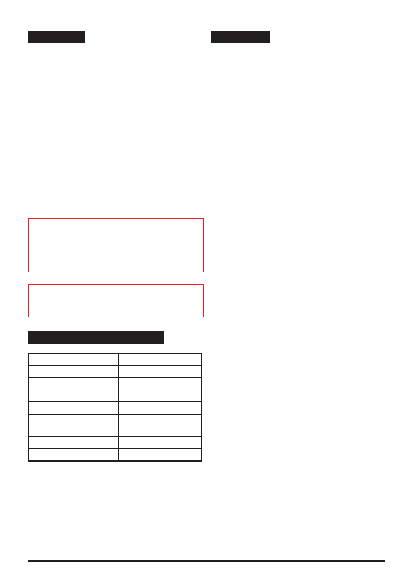
Features
ÿ One location message of 11 seconds, and
3 alarm messages of 3 seconds each.
ÿ Recorded messages stored in non-volatile
memory.
ÿ
All telephone numbers stored in non-volatile
memory.
ÿ
Unique, easy to use, “Follow Me” telephone
number.
ÿ
Three trigger inputs, programmable as active
high or low, linked to phone numbers or
alarm messages.
ÿ
Unique Inhibit input for use with “Bells
only” control panels.
ÿ
Last event memory.
ÿ
Comprehensive test facilities.
ÿ
Supplied with telephone lead for easy
installation.
Speech Dialler
Engineering Information
Description
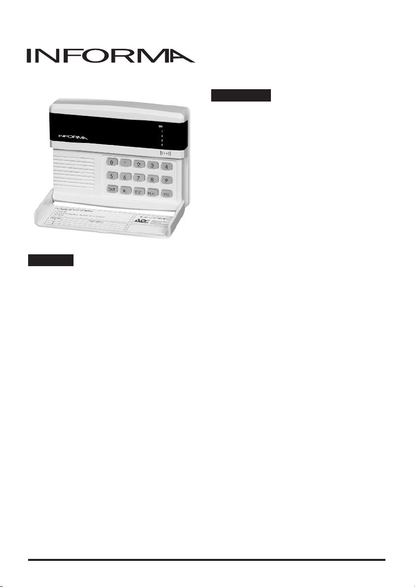
The ADE Informa is a Speech Dialler for use
with intruder alarm systems. When the control
panel recognises an alarm it will trigger the
Informa. The Informa will use a telephone line
to dial a pre-programmed telephone number, and
replay a previously recorded message, thereby
alerting the recipient of the call to the alarm and
potential intrusion.
The recipient must acknowledge the call. If he
fails to do this then the message will be repeated
a number of times. After this the Informa will
hang-up and dial a second, and third, telephone
number, replaying the message each time. If the
Informa fails to be acknowledged it will repeat
this sequence a further 6 times.
1
Page 2

Engineering information
Contents
Features -------------------1
Description -----------------1
Overview ------------------1
Messages ------------------2
Telephone Numbers -------------2
Operating Mode ---------------3
Mode A -------------------3
Mode B -------------------3
Message Acknowledgement ---------3
Inhibit Input -----------------3
Power Supply Connections ----------5
Bells only control panel -----------5
Communicating Control Panels --------6
Connecting to ADE Accenta G3 -------6
Connecting to ADE Karizma ---------6
Connecting to ADE Karizma Plus -------6
Connection to the Telephone ---------7
Network ------------------7
Using the Supplied Telephone Lead -----7
Direct Connection to a Master Jack ------7
Parallel Connection -------------8
PABX Connection --------------8
Payphones------------------8
Engineer Programming ------------9
Monitor Mode [0] --------------9
Dialling Format [1] -------------9
Message Timeout [2] -------------10
Input Association [3] -------------10
Trigger Levels [4] --------------10
Last Event Memory [5]------------10
Enable the Follow Me function [6] ------11
Change Customer Code [8] ----------11
Change Engineer Code [9] ----------11
Recording Messages [REC] ---------11
Replaying Messages [PLAY] ---------12
Test Calls [TEST] --------------12
Programming Telephone -----------12
Numbers [TEL] ---------------12
Quit engineer Mode [QUIT] ---------12
NVM Reset -----------------13
Factory settings (defaults) ----------13
Application -----------------13
Ringer Equivalence Number ---------13
Technical Specifications -----------14
Quick Reference ---------------17
Messages
The Informa can record 4 spoken messages in its
non-volatile memory. Message number 1 (the
location message) may be up to 11 seconds long,
messages 2, 3 and 4 may be up to 3 seconds and
are used as the alarm messages.
When the Informa makes a call it will always
replay the location message first.
Typically the Location message is used to
ÿ
identify the location of the Informa, e.g.
“This is the Alarm Panel at the house of
Fred Smith in Wigan”.
The other 3 messages are called alarm
ÿ
messages and are normally used to indicate
the type of alarm or problem that has
occurred, e.g. “Intruder”, “Fire” and
“Personal Attack”
Telephone Numbers
The Informa can be programmed to accept up to
4 telephone numbers. Three of these numbers
are permanently stored via the Engineer program
in the NVM. The fourth phone number can be
programmed by the customer and is called
"Follow Me".
The "Follow Me" telephone number is entered
into the Informa (If required), before the system
is set. When the system is unset the Follow Me
telephone number will be removed and forgotten
by the Informa. The Follow Me feature, is
designed to be used by customers, who may
move from location to location on a regular
basis. The customer can re-program the Follow
Me number each time that he leaves the
premises and sets the alarm system.
2
Page 3

Informa - Speech Dialler
Operating Mode
The Informa has 3 inputs, labelled IP1 to IP3 on
the PCB, which should be connected to the
control panel communicator outputs. Any of
these can be used to trigger the Informa, causing
it to communicate its message in the event of an
alarm.
The Informa can be programmed to use one of
two modes of operation. It can either associate
an input IP1-IP3 with an alarm message (mode
A), or with a telephone number (mode B).
Mode A
If the Follow Me number is valid it will dial this
first, otherwise it will dial the first telephone
number. It will replay the location message,
followed by the alarm message associated with
the triggered input, where IP1 plays message 2,
IP3 plays message 3, etc.
Location message: This is the alarm system at
Mr and Mrs Smith's house, 1 the avenue, Smith
Town.
Alarm message: There is an intruder alarm
activation.
If two inputs are triggered at the same time the
Informa will replay both alarm messages. If the
Informa isn’t acknowledged it will attempt to
communicate to the 2nd telephone number, then
the 3rd, see Message Acknowledgement.
Mode B
If IP1 has been triggered the Informa will only
dial the first telephone number, and replay the
location message followed by message 2.IfIP2
has been triggered the Informa will dial the
second telephone number, and replay the
location message followed by message 3,
similarly for IP3. If the Informa isn’t
acknowledged it will only attempt to
communicate to the original telephone number.
Message Acknowledgement
The recipient must always acknowledge the call
made by the Informa in order to terminate its
dialling sequence. After replaying its two or
more messages the Informa will produce a single
tone for 1 second. The recipient must then press
the“*“(star) key on the telephone for 1
second. The Informa will repeat its tone for 1
second, and the user must again press the“*“
key for 1 second. The Informa will then sound 2
short beeps to indicate that it has received the
acknowledgement and then hang-up. Note that it
is possible to acknowledge the call only by use
of a tone dialling telephone.
Inhibit Input
The Informa may be used with a bells-only
panel, such as an ADE Logic 4/6 and Optima
compact G3. In this case trigger IP1 must be
connected to the Bell output of the panel.
To prevent the Informa from being triggered
when the customer carries out a Bell test, the
inhibit input (labelled INH on the PCB) must be
connected to the SET output from the panel. The
Informa will be triggered by the bell only when
the panel has been set. Note also the PA only
triggers the Informa in SET mode.
"
alarms from IP1. Also the PA only triggers
Informa in SET mode.
The INH input is also used with the “Follow
Me” function. If the “Follow Me” function has
been enabled the INH input will no longer
inhibit alarms from IP1, instead it is used to
cancel the “Follow Me” number whenever the
panel is Unset. It should be connected to the
SET output from the control panel.
A customer could enter a Follow Me contact
number into the Informa before going away on
holiday. If the system should go into alarm the
Informa will call this new number first followed
by the other pre-programmed numbers.
The INH input will only inhibit
3
Page 4
Engineering information
Vol
l
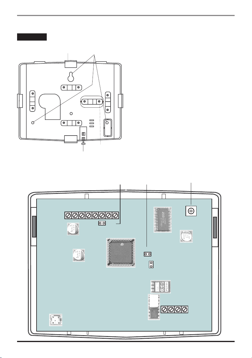
Installation
Mounting
4-Cable entry breakouts
for mini trunking
Cover fixing screw
12V
0V
Wall fixing points
Breakout cable strap
INH
IP3
IP2
IP1
TAMP
V1.1
Before installing the Informa power down the
control panel it is to be connected to by
removing both mains and battery power. Break
out the cable clamp strap from the back plate.
Fasten the Informa’s backplate securely to the
required position on a wall, breaking out which
ever cable entry is going to be used. The cut outs
are designed to take mini trunking directly. Run
the cable from the alarm panel down to the
Informa back plate as required.
Run the cable from the position of the telephone
master socket up to the Informa back plate.
Secure both of these cable to the nearest cable
clamp using the cable clamp strap removed
earlier. Use the 2 small self tapping screws to
fasten the clamp strap across the 2 cables.
link
NVM link
ume contro
R72
VOLUME
NVM
L3
RESET
J1
APEB
TAMP
BC
4
Page 5
Informa - Speech Dialler
Power Supply Connections
Connect the alarm cable wiring, starting with the
+12V and 0V connections from the alarm panel,
and wire them into the +12V and 0V terminals
of the Informa. Next wire as many trigger
channels from the alarm panel to the speech
dialler as required.
"
provide power to the Informa must be
approved for such use by BABT, and
additionally the power supply feed to the
Informa must be fused at 2A or less. If the
control panel is not being used as
the power supply for Informa then a
common 0V connection between the
control panel and Informa must be
made.
The equipment that is used to
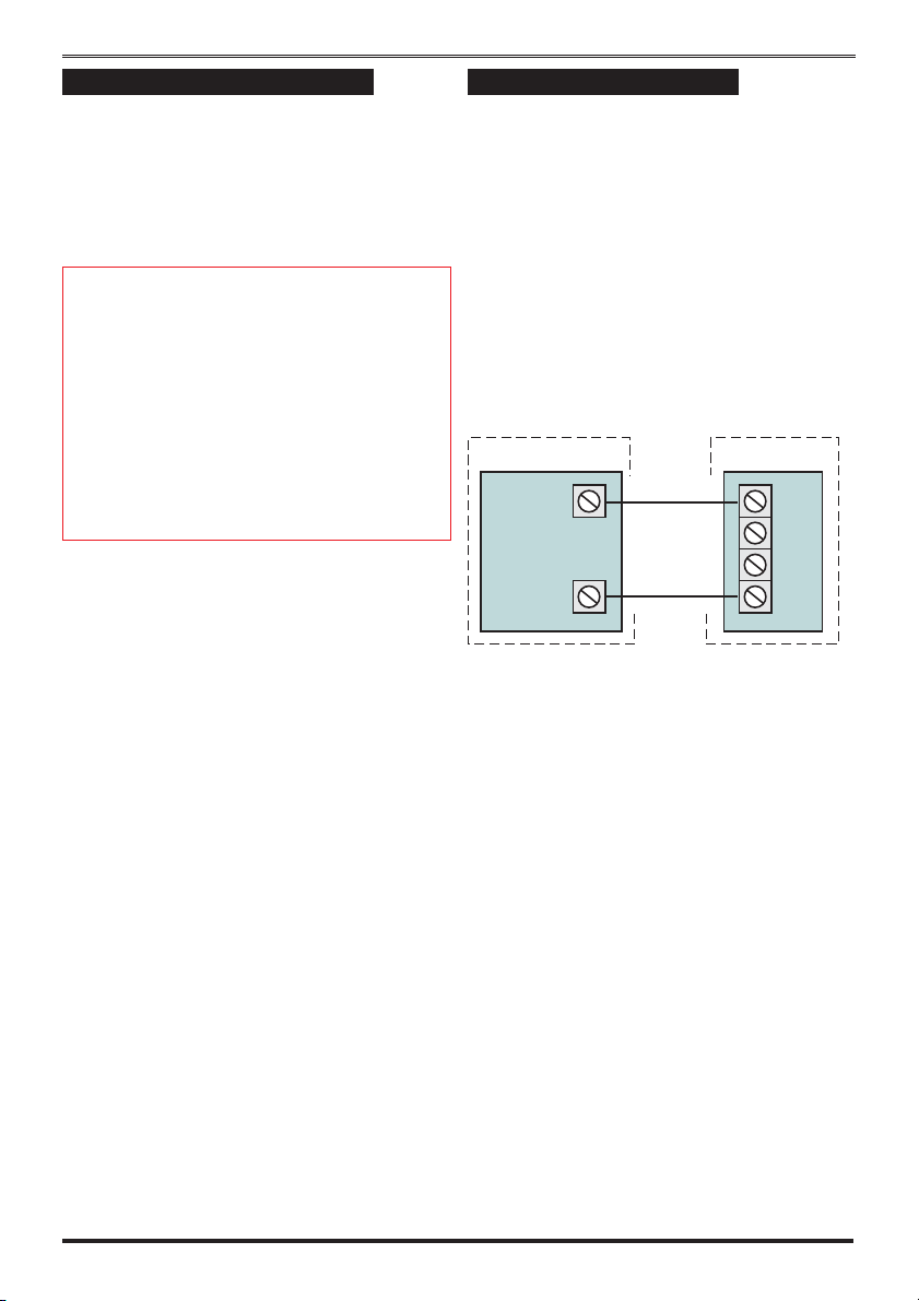
Bells only control panel
ADE Logic 4/6 and Optima compact G3 panels
are a bells-only panels. With these control panel
Informa may be used as a single channel dialler
by being triggered from the Bell output. Most
control panels use 0V - (negative) to trigger the
bell or sounder. If the control panel used has a bell trigger, Informa's inputs must be
programmed as active low (- trigger). See
Trigger levels. The factory default for these
inputs is Active Low. The following describes
how Informa should be connected to these
panels.
a) Connect Informa as shown:
Control panel Informa
SET+
BELL B-
Set +: By making the SET +
connection to the Informa a bell test
will not trigger the Informa. Also a PA
will not trigger the Informa unless the
panel is in Set Mode.
b) Program Informa’s inputs IP1 to IP3 as
active low (the default).
c) Program the INH input as active high.
d) Make sure that the Follow Me function
is disabled (see Enable the Follow Me
function)
INH
IP3
IP2
IP1
5
Page 6
Engineering information
Communicating Control Panels
Most communicating control panels use a +ve
(positive) to trigger the communicator outputs. If
the control panel used has a +ve communicator
output, Informa inputs must be programmed as
active high (+ve trigger), see Trigger Levels.
The Optima and Accenta G3, Accenta Ideal,
Karizma, Karizma + and Karizma UDL all have
a dedicated communicator or programmable
communicator outputs. This will allow a location
message followed by one of three alarm
messages to be sent, by Informa.
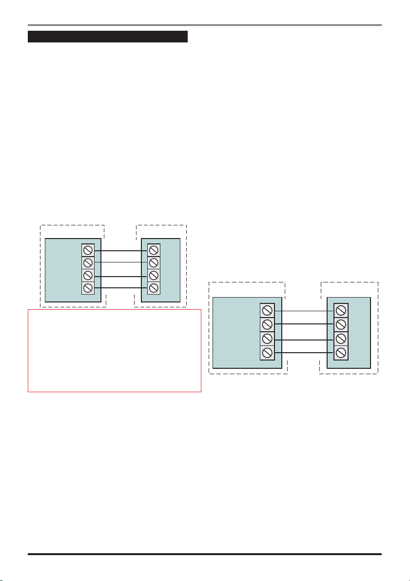
Connecting to ADE Accenta G3
Three channel (3 message) operation is possible
with an ADE Accenta G3. Connect Informa to
the Accenta G3.
Control panel Informa
SET
FIRE
PA
INT
INH
IP3
IP2
IP1
a) Program all Informa inputs as active
high.
b) Connect Informa to the outputs of the
Signal Interface module as shown for
ADE Accenta G3.
c) If the Follow Me function is to be used
then connect the INH input to the SET
output of the Signal Interface module,
and enable the Follow Me function (see
section Enable the Follow Me function).
If Follow Me is not to be used then do
not make this connection.
Connecting to ADE Karizma Plus
Informa may be connected to outputs P1 to P4
on the Karizma Plus.
a) Program the control panel output ports
P1 to P4 to give the following outputs:
Fire, PA, Intruder and Set.
b) Program all Informa’s inputs as active
low (the default).
c) Connect Informa to these outputs as
shown:
Control panel Informa
"
connected to the INH input on the Informa. This
enables the use of the Follow Me function, see
section Enable the Follow Me function.If
Follow Me is not to be used then do not make
this connection.
Program all Informa inputs as active low (this is
the default).
The SET + of the panel is
Connecting to ADE Karizma
With this control panel the Informa may be used
as a single channel dialler by being triggered
from the Bell output. Connections and
programming are described for ADE Accenta
G3.
To use Informa as a 3 channel dialler an ADE
Signal Interface module is required, which plugs
onto the two rows of communicator pins on the
control panel PCB, and gives terminal
connections to Fire, PA, Intruder and Set.
6
P4 (SET)
P3 (FIRE)
P2 (PA)
P1 (INT)
d) If the Follow Me function is to be used
then connect the INH input to the SET
output (P4) of the control panel, and
enable the Follow Me function (see
section ). If Follow Me is not to be used
then do not make this connection.
An alternative method of connection exists for
Karizma Plus. An ADE Signal Interface module
can be plugged onto the two rows of
communicator pins, and Informa can be
connected to its terminals. See Connecting to
ADE Karizma.
INH
IP3
IP2
IP1
Page 7

Connection to the Telephone
Network
ADE recommend that the Informa should be
connected to an ex-directory standard PSTN
telephone line, and that ideally no other
telephone apparatus should be connected to the
same line.
Informa may be connected to the telephone
network by either of these two methods:
a) Use the supplied telephone lead and
plug, which can be plugged into a
standard BT jack socket, see Using the
Supplied Telephone Lead.
b) Use direct connection to a BT master
jack socket using special telephone
cable, see Direct Connection to a
Master jack.
Using the Supplied Telephone Lead
A 1.5m telephone lead (and plug) is supplied for
convenient connection to a standard BT jack
socket. This 4-way lead must be wired to the
terminals on the Informa PCB in the following
way:
Wire Colour PCB Terminal
White A
Red B
Blue BC
Green Not connected
Informa - Speech Dialler
Direct Connection to a Master Jack
Direct connection to a NTE5 master jack socket
should be undertaken by an approved installer.
Connection should be made to the NTE5 master
socket using the connections described below.
The cable used to connect the Informa to the
master socket must conform to BT specification
CW1308. This has a single strand conductor of
2
. On no account should cable of any
0.5mm
other type be used.
At the NTE5 master socket identify the terminals
A, B, and BC. This can be done either by
reference to the terminal numbers on the NTE5
socket, or by the OFTEL wiring code.
Terminal Number Wire Colour
A5
B2
BC 3
Connect one end of the telephone cable to the
Informa terminals labelled A, B and BC. Strip
back 5mm of insulation from each of
3 conductors, insert the conductors into the
terminal block, and tighten the screw. The
telephone cable should be routed clear of all
other cables inside the housing.
Connect the other end of the telephone cable to
the NTE5 master socket. It may be necessary to
use a special IDT termination tool to do this
securely.
white with blue
rings
blue with white
rings
orange with white
rings
For added protection against damage by nearby
lightening strikes the Informa has an additional
earth terminal, identified as “PE”. Connect this
terminal to a nearby electrical earth using a cable
of at least 1.0mm
the protection will not be effective.
2
. If this connection is not made
7
Page 8

Engineering information
Parallel Connection
Although not recommended by ADE, the
Informa may be connected to the same telephone
line as other telephone apparatus. The Informa
may only be connected in parallel with other
apparatus, since a series connection facility is
not provided. When connected in this way the
installer should check that the combined REN of
all equipment connected in parallel does not
exceed the maximum REN permitted by BT.
PABX Connection
The Informa will operate on most PABX
systems. The person responsible for connection
of the Informa to a PABX system is as follows:
If the wiring is owned by BT, then BT.
If the wiring is not owned by BT then either:
(i) BT,
(ii) the authorised maintainer, or
(iii) a professional installer after, 14 days written
notice to the authorised maintainer.
When used on a PABX system the Informa may
need access an “outside line” before attempting
to dial any telephone number. In this case all
telephone numbers programmed into the host
control panel should be prefixed with the
“outside line” code of the PABX. This is usually
“9”.
Payphones
The Informa is not suitable for connection as an
extension to a payphone or1+1carrier system.
8
Page 9

Programming
1
2
3
4
1ON2 3 40
6 7 8 95
TELQUIT TEST PLAY REC
Informa - Speech Dialler
Monitor Mode [0]
Monitor mode displays the programmed state of
each input to the Informa. LED 1 and LED 3
match inputs 1 to 3 and LED 4 will display the
state of INH input. If LED is lit then the input is
programmed as active high (+ve trigger). If no
LED is lit then the input is programmed as active
low (-ve trigger), see Trigger Level.
a) Press [0] to enter Monitor Mode. The
state of the inputs will be displayed on
the 4 LED’s. LED’s 1 to 3 show the
state of inputs IP1 to IP3, LED 4 shows
the state of the inhibit input (INH). An
LED will be lit when the associated
input is active. Note that the inputs can
be programmed to be active high or
low.
b) Press QUIT to quit this mode.
Engineer Programming
The Informa is in standby mode when only the
green Power LED - "ON" is lit.
a) To enter the engineers’ menu, key in
the 4 digit engineer code and the first
three red LED’s will light. The default
engineer code is 9999.
From the engineer’s menu the following
commands are available:
Dialling Format [1]
You can program the Informa to work in one of
three dialling modes. By default the Informa will
use Auto-detection, format [3].
a) Press 1 to change the dialling format.
b) Press:
[1] to select Pulse dialling,
[2] to select Tone dialling,
c) [3] to select Auto-detection of the
dialling format.
When you have chosen the setting the
Informa automatically resets to top
level of the Engineering controls.
9
Page 10

Engineering information
Message Timeout [2]
This facility allows the Informa to repeat the
triggered messages more than once to the
programmed numbers. It is recommended that
this message time is at least twice as long as
your recorded messages.
Example: If the location message plus Alarm
message equals 15 seconds, then the Message
Timeout setting must be 30 seconds.
"
the line is connected, whether the phone is
answered on not.
When the Informa makes a call it will always
play-back its messages for a fixed length of time
before it hangs-up and tries another number. The
fixed length of time is called the Message
timeout and can be set by the engineer to
between 5 and 99 seconds.
a) Press [2] to change the Message
timeout.
b) Type in the 2 digit number between 05
to 99 seconds. If you need 30 seconds,
type in 3 0.When you have chosen the
setting the Informa automatically resets
to top level of the Engineering controls.
Messages will playback as soon as
Input Association [3]
The Informa can associate each of its three
inputs either with a message, or a telephone
number, see Operating Mode.
a) Press [3] to change the Input
association.
b) Press:
[1] inputs associate with a message
[2] inputs associate with a telephone
number.
When you have chosen the setting the
Informa automatically resets to top
level of the Engineering controls.
Trigger Levels [4]
The three inputs (IP1 to IP3), and the inhibit
input (INH), can be individually programmed as
active high (+ve trigger) or active low (-ve
trigger). An active high input will trigger the
Informa when the voltage present at the input
exceeds 3.5V (maximum is 15V). An active low
input will trigger the Informa when the voltage
is less than 1.0V.
a) Press [4] to change the Trigger levels.
The 4 LED’s show the trigger level of
inputs 1 to 3, and the inhibit input,
respectively. A lit LED shows that the
input is programmed as active high.
b) Press keys 1 to 4 to toggle (switch) the
trigger level of the inputs, between
active high (+ve trigger) and active low
(-ve trigger).
c) Press [PLAY] when finished, or [QUIT]
to ignore any changes.
The Informa automatically resets to top
level of the Engineering controls.
Last Event Memory [5]
When Informa is triggered it will log the trigger
input (IP1 to IP3) in its event memory.
a) To view this memory press [5]. One of
the LED’s will light, indicating the Input
which last triggered Informa. If the LED
lights steady it indicates that the call
was successfully acknowledged, if the
LED flashes it indicates that the call
was not acknowledged.
b) When you have viewed the event log
press [Quit] and the Informa
automatically resets to top level of the
Engineering controls
10
Page 11

Informa - Speech Dialler
Enable the Follow Me function [6]
The Follow Me function permits the customer to
enter a telephone number each time that the
alarm system is set. The Informa will always use
the Follow Me number (if programmed) in
preference to the 1st telephone number.
a) Press [6] to enable of disable the
Followed Me function.
b) Press [0] to disable the Follow Me
function (LED 4 lit) or
Press [1] to enable the Follow Me
function (LED 1 lit)
Change Customer Code [8]
Access to the customer menu, for the
programming of messages and telephone
numbers, is protected by a 4 digit code. This can
be changed either by the customer or the
engineer. To change the customer code:
a) Press [8] to enter change customer
code.
b) Enter new 4 digit code. If the code is
the same as the engineer code the
Informa will not accept it and sound an
error tone.
c) When you have changed the code the
Informa automatically resets to top
level of the Engineering controls
Change Engineer Code [9]
To change the engineer code.
a) Press [9] followed by the new 4 digit
code. If the code is the same as the
customer code the Informa will not
accept it and sound an error tone.
Recording Messages [REC]
You can program up to four messages into your
Informa speech dialler. Message 1 is designed as
the Location message and can be up to 11
seconds long. Message 2, 3 and 4 are designed
for your Alarm messages and can each be three
seconds long.
To record or re-record a message
a) Press [REC] followed by the message
number 1 to 4, where 1 corresponds to
the location message. The Informa will
pause for 1 second then sound a tone
for 1 second.
b) Now speak clearly into the microphone,
which is just below the LED’s. Message
1 may be up to 11 seconds long, the 3
alarm messages are 3 seconds long.
Example
Location message can be:
message 1- "This is the alarm
system at Mr & Mrs Smith's house, 1
The Avenue, Smith Town. There is"
The Alarm message can be:
message 2- "Fire alarm"
message 3- "Personal attack"
message 4- "Intruder Alarm"
The Informa will automatically stop
recording at the end of the message
duration. If the announcement to be
recorded in message 1 is much shorter
than 11 seconds you can stop the
recording at any time by pressing
[PLAY].
c) After the message is recorded there
will be a short delay and the Informa
will repeat your recorded message.
11
Page 12

Engineering information
Replaying Messages [PLAY]
To replay any of the messages previously
recorded:
a) Press [PLAY].
b) Press the number of the message to
be played (1 to 4). After a short delay
the Informa will replay the selected
message. Message 1 is the location
message and Messages 2, 3 and 4 are
alarm messages.
c) The playback volume can be adjusted
(ON SITE) by adjusting the internal
volume pot on the Informa PCB - R72.
Test Calls [TEST]
To test that the telephone numbers have been set
up correctly the Informa can perform a test call.
During a test call the play-back speaker will be
turned on so that you can hear how the call
progresses. To generate a test call:
a) Press [TEST].
b) Enter the telephone number (1 to 3) to
be tested. The Informa will dial the
number, replay message 1 followed by
message 2. Listen for the acknowledge
signal. If the Informa receives a valid
acknowledgement it will hang-up the
line and light all 4 LED’s steady.Ifit
fails to receive an acknowledgement it
will repeat its messages for the
duration of the Message timeout, and
then hang-up the line and flash all 4
LED’s.
c) Press [TEST] again to end the
sequence. Informa will automatically
reset to the top level of the Engineering
mode.
Programming Telephone
Numbers [TEL]
Up to three 20 digit telephone numbers can be
programmed into your Informa.
"
me telephone number, which is programmed
when the system is set.
To program any of the 3 telephone numbers:
a) Press [TEL].
b) Now select the telephone number (1 to
3) you want to change.
c) Enter the digits of the telephone
number, up to 20 digits are allowed.
Press [REC] to add a pause of
1 second if required. Each press of
[REC] button consume 1 digit from the
20 digits allowed.
Now press either:
[TEL] to accept the telephone number
just entered
[QUIT] to reject the number if you
made a mistake
[TEST] to accept the number just
entered and immediately make a test
call to that number.
To delete a telephone number
a) Press [TEL].
b) Now select the telephone number to be
deleted (1 to 3)
c) Press [TEL].
This does not include your follow
Quit engineer Mode [QUIT]
Having completed all programming and test
calls, you can return Informa to standby:
a) Press the [QUIT] key to quit engineer
mode.
12
Page 13
Informa - Speech Dialler
NVM Reset
The engineer code, and all other programmable
parameters, can be reset back to their factory
defaults by following this sequence:
a) Power down the Informa by removing
the 12V supply to the Informa.
b) Slacken the front cover screw and
remove the front assembly to view the
PCB.
c) Short together the 2 pins labelled
“NVM” L3 with the blade of a
screwdriver, and at the same time
power up the Informa. The NVM will be
reset.
d) Now remove the short from the 2 pins,
your Informa will return to the factory
setting.
"
the messages that have previously been
recorded.
"
The above sequence will not clear
Link V1.1 should not be fitted.
Factory settings (defaults)
Application
The Informa is suitable for connection to the
following types of telephone line:
a) Direct exchange lines (PSTN)
supporting either DTMF (tone) or Loop
Disconnect (pulse) dialling.
b) PABX exchanges, with or without
secondary proceed indication.
The Informa can be used for the following:
Automatic call initialisation
ÿ
Operation in the absence of a proceed
ÿ
indication
Automatic calling
ÿ
Multiple repeat attempts
ÿ
It is recommended that the equipment is set to
use DTMF dialling for access to public or
private emergency services.
Ringer Equivalence Number
The Ringer Equivalence Number (REN) of the
Informa is 1. The sum of the REN values of all
telephone apparatus connected to a single line
should not exceed 4. The REN of most apparatus
is marked on the “green dot” approval sticker.
Where the REN is not specified it is assumed to
be 1.
Engineer Code 9999
Customer Code 0123
Dialling format Auto-detect (3)
Message Timeout 45 seconds
Input Association Messages (1)
Trigger Levels
Follow Me function Disabled
Telephone numbers All blank
All inputs active
low
13
Page 14

Engineering information
Technical Specifications
Power supply provided by the host control panel
power supply voltage 10 to 18V (max)
power supply current 50mA quiescent, 200mA (max) when operating
Negative Input Trigger voltage < 1.0V
Positive input Trigger voltage 3.5V to 15V (max)
Temperature range (operating) 0 to 60ºC
Dialling method
BT Ringer Equivalence Number (REN) REN = 1
DTMF (tone), Loop Disconnect (pulse),
Auto-detect
Index
A
Accenta G3 .........6
Alarm message .......2,3,10,11
B
BABT ............5
BT jack socket .......7
C
Cable clamp strap ......4
Location message ......1,2,3,10,11
Customer Code .......11
D
Dialling Format .......9
DTMF............13
E
Engineer Code .......11
Engineer Mode .......12
Engineer Programming . . . 9
Event Memory .......10
F
Follow Me .........1,2,3,11
I
INH.............3
Inhibit input .........1
Input Association ......10
IP1toIP3..........3
L
Logic 4/6 ..........5
M
Message Timeout ......10
Monitor Mode .......9
N
Negative Input Trigger . . . 14
NTE5 master jack socket . . 7
NVM Reset .........13
O
Optima compact G3 ....5
P
PABX ............8,13
Positive input Trigger ....14
PSTN ............7,13
R
Recorded messages .....1
Recording Messages ....11
REN.............8,13,14
Replaying Messages ....12
T
Telephone Numbers ....12
Test Calls ..........12
Trigger inputs ........1
Trigger Levels .......10
K
Karizma ...........6
Karizma Plus ........6
14
Page 15

Notes
Informa - Speech Dialler
15
Page 16

Engineering information
g
Quick Reference
9 9 9 9
Enter
Engineer Program Mode
QUIT QUIT
To exit
Engineer Program Mode
LED On Steady
LED On Flashing
1
2
3
4
5
6
8
9
Dialling format
Message timeout
Mode
Trigger levels
Last trigger
event memory
Follow me
Change
Customer code
Change
Engineer code
1
for message 1 (common message)
2
for message 2 (alarm message)
3
for message 3 (alarm message)
for message 4 (alarm message)
4
1
2
3
n n
1
2
1
2
3
4
ON - Call was successfully acknowledged
Flashing - Call has not been acknowledged
0
1
Pulse
Tone
Auto detect
(nn can be a number: 05 - to - 99)
Seconds
Inputs - message
Inputs - Telephone number
IP1
IP2
IP3
INH
Disable
Enable
LED 1
LED 2
LED 3
LED 4
ON - Active high
trigger level
OFF - Active low
trigger level
LED 4 -ON = Function disabled
LED1-ON=Function enabled
n n n n
Enter new 4-digit code
PLAY
Store changes
QUIT
QUIT
PLAY
End recording
1
PLAY
TEL
TEST
for message 1 (common message)
2
for message 2 (alarm message)
3
for message 3 (alarm message)
for message 4 (alarm message)
4
Program
telephone
number
Test Call
LED 1
LED 2
LED 3
1
2
3
Tel. No. 1
Tel. No. 2
Tel. No. 3
1
Tel. No. 1
2
3
Tel. No. 2
Tel. No. 3
nn n n
LED 1 to LED 4 If acknowledgement
is received
LED 1 to LED 4 If call is not
acknowled
To add
REC
1 second pause
Telephone number
maximum 20 digits
ed
TEL
to accept
to reject
QUIT
TEST
to accept and
make at test call
TEST
End test sequence
For Technical Support
: 01268 563 270
Novar ED&S
The Arnold Centre
Paycocke Road
Basildon
SS14 3EA
16 4188-767_issue 1_07/03
Page 17

What is Informa?
The Informa is a keypad unit that has the
capability of dialling prerecorded speech
messages over a telephone line. It is installed in
your intruder system so that when your alarm
system detects an intrusion the external siren
will sound to alert your neighbours and the
Informa will dial a programmed telephone
number and replay a recorded speech message to
alert someone else to the intrusion. For example,
Informa can contact a friend or relative who
lives close to your home, who can investigate the
alarm and call the police if necessary.
What Does Informa Need to Know?
Before Informa can work you must program it
with the telephone numbers to use, and record
the alarm messages that it will replay.
Messages
Informa can record 4 spoken messages in its
memory. Message number 1 location message
may be up to 11 seconds long, messages 2, 3 and
4 alarm messages may be up to 3 seconds each.
When Informa makes a call it will always replay
the location message first. Typically the location
message is used to identify the location of
Informa, e.g.
“This is the Alarm Panel at the house of Fred
Smith in Wigan”.
The other 3 messages are called alarm messages
and are normally used to indicate the type of
alarm or problem that has occurred, e.g.
“Intruder”, “Fire”, “Personal Attack” etc. Your
installer will tell you which alarm messages can
be used with your intruder alarm system.
Telephone Numbers
Informa can contact up to 3 telephone numbers.
The best people to contact are friends and
relatives who live close to your home, who can
carry out an initial investigation of the alarm,
Speech Dialler
Operating Instructions
and then contact the police. Informa can also be
programmed to contact your mobile phone, but
unless you work close to home this may not be
very useful. Informa has 3 memories for storing
the telephone numbers. It will try each one in
turn until its call is acknowledged, so you should
always program the first memory with the
number of the person most likely to answer the
call.
The person who answers the call from Informa
must acknowledge it by following a simple
procedure (described later). If he or she fails to
do this then Informa will hang-up and dial a
second telephone number, and replay the
message again. If it isn’t acknowledged it will
try a third number. If Informa fails to be
acknowledged it will repeat this sequence a
further 6 times. It is therefore very important that
the person who answers the call understands
how to acknowledge a call.
Operating Mode
The Informa can be programmed to use one of
two modes of operation. It can either associate
an input with an alarm message (mode A), or
with a telephone number (mode B).
Note: Please check with the installer which of
the mode has been set.
Mode A
If the Follow Me number is valid it will dial this
first, otherwise it will dial the first telephone
number. It will replay the location message,
followed by the alarm message associated with
the triggered input, where IP1 plays message 2,
IP3 plays message 3, etc.
location message: This is the alarm system at
Mr and Mrs Smith's house, 1 the avenue, Smith
Town.
Alarm message: There is an intruder alarm
activation.
1
Page 18

Engineering information
If two inputs are triggered at the same time the
Informa will replay both alarm messages. If the
Informa isn’t acknowledged it will attempt to
communicate to the 2nd telephone number, then
the 3rd, see Message Acknowledgement.
Mode B
If IP1 has been triggered the Informa will only
dial the first telephone number, and replay the
location message followed by message 2.IfIP2
has been triggered the Informa will dial the
second telephone number, and replay the
location message followed by message 3,
similarly for IP3. If the Informa isn’t
acknowledged it will only attempt to
communicate to the original telephone number.
How Do I Program Informa?
Informa is in standby mode when only the green
Power LED "ON led is lit. To program Informa
you must enter programming mode by keying in
a 4 digit code on the keypad. By default this
code is 0123 but your installer may have
changed it. Key in the code. If it is valid all 4 red
LED indicators will light. Once in programming
mode you can carry out any of the following
functions:
To Change a Telephone Number
a) Press the button labelled TEL.
b) Press the memory to be changed (1, 2
or 3)
c) Enter the digits of the telephone
number, up to 20 digits are allowed.
d) Press TEL to accept the number.
If you make a mistake press QUIT to reject the
entire number.
Note: The Informa cannot contact the
emergency services directly. It will not accept
any telephone number starting with 999 or
112.
To Delete a Telephone Number
a) Press TEL
b) Press the memory to be deleted (1, 2
or 3)
c) Press TEL
To Record a Message
a) Press REC. LED’s 1 to 4 will flash
b) Press the message number to be
recorded (1, 2, 3 or 4)
Informa will pause for 1 second then
sound a tone for 1 second.
c) Now speak clearly into the microphone,
which is just below the LED’s.
Message 1 (the location message) may be up to
11 seconds long, the 3 alarm messages are 3
seconds long. Informa will automatically stop
recording at the end of the message duration. If
the announcement to be recorded in message 1 is
much shorter than 11 seconds you can stop the
recording at any time by pressing PLAY. After a
short delay Informa will replay the message just
recorded.
To Replay Messages
a) Press PLAY. LED’s 1 to 4 will flash.
b) Press the message number to be
replayed (1, 2, 3 or 4)
After a short delay Informa will replay the
selected message.
To Test Informa
To test that the telephone numbers have been set
up correctly Informa can perform a test call.
During a test call the play-back speaker will be
turned on so that you can hear how the call
progresses. To generate a test call:
a) Press TEST. LED’s 1 to 3 will flash.
b) Press the telephone memory to be
called (1 to 3).
Informa will dial the number, replay location
message followed by alarm message 2, and
listen for the acknowledge signal. If Informa
receives a valid acknowledgement it will
hang-up the line and light all 4 LED’s steady. If
it fails to receive an acknowledgement it will
repeat its messages several times, and then
hang-up the line and flash all 4 LED’s. Press
TEST again to cancel this.
To Change the Code
a) Press 8
b) Key in the new 4 digit code.
Informa will not accept certain codes, in which
case it will sound an error tone.
2
Page 19

Using Informa
In Normal use
Once programmed Informa needs no further
programming or attention. Set and unset your
alarm system as directed by your installer. In the
event of an alarm Informa will carry out its
function reliably and silently.
Cancelling a Call
If you accidentally set off your alarm system the
Informa will attempt to communicate its alarm
message. You can stop this by keying in your
code on Informa’s keypad. Informa will
acknowledge that the call has been cancelled by
flashing all 4 LED’s for several seconds.
Message Acknowledgement
The person who answers the telephone call from
Informa must always acknowledge the call. This
is done by the following:
a) When you answer a call from an
Informa, listen to the message. At the
end of the message Informa will
produce a single tone for 1 second.
b) Press the * (star) key on the telephone
for at least 1 second. Informa will
repeat its tone for 1 second.
c) Press the * key again for 1 second.
Informa will then sound 2 short beeps
to indicate that it has received the
acknowledgement and then hang-up.
It is possible to acknowledge the call only by
use of a tone dialling telephone.
Informa - Speech Dialler
INFORMA
Acknowledgement Instructions
When you answer a call from an Informa,
ÿ
listen to the message. At the end of the
message Informa will produce a single
tone for 1 second.
Press the * (star) key on the telephone for
ÿ
at least 1 second.
Informa will repeat its tone for 1 second.
ÿ
Press the * (star) key again for 1 second.
ÿ
Informa will then sound 2 short beeps to
ÿ
indicate that it has received the
acknowledgement and then hang-up.
INFORMA
Acknowledgement Instructions
When you answer a call from an Informa,
ÿ
listen to the message. At the end of the
message Informa will produce a single
tone for 1 second.
ÿ
Press the * (star) key on the telephone for
at least 1 second.
ÿ Informa will repeat its tone for 1 second.
ÿ
Press the * (star) key again for 1 second.
ÿ
Informa will then sound 2 short beeps to
indicate that it has received the
acknowledgement and then hang-up.
The Follow Me Number
Informa also has a Follow Me number, that you
can easily re-program each time that you leave
the house and set the alarm system. If a Follow
Me number has been programmed Informa will
always attempt to contact that number first. The
Follow Me number is cancelled each time that
the alarm system is unset. The Follow Me
number can be changed without entering
programming mode.
a) Press TEL.
b) Key in the telephone number (up to 20
digits).
c) Press TEL.
Cut out the acknowledgement instructions above
and carry it with you for reference.
3
Page 20

Engineering information
Installer Details
You too could benefit from the added
security and peace of mind only an
INFORMA can bring!
Contact you Installer (details below)
Company: ____________________
Contact: ______________________
Address_______________________
__________________________________
You too could benefit from the added
security and peace of mind only an
INFORMA can bring!
Contact you Installer (details below)
Company: ____________________
Contact: ______________________
Address_______________________
Company___________________________
Contact Name____________________
Address:_____________________________
____________________________________
____________________________________
__________________________________
For Technical Support
: 0906 302 0999
This is a premium rate line, calls are
charged at 50 pence per minute
Novar ED&S
The Arnold Centre
Paycocke Road
Basildon
SS14 3EA
4 4188-767 _issue 1_07/03
 Loading...