

Page 1
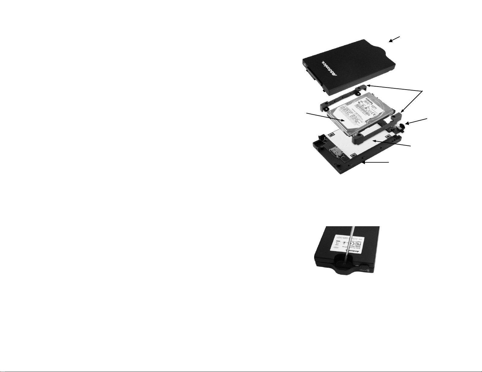
shock
absorbers
PCB
top cover
2.5” SATA
hard drive
bottom cover
switch
Addonics
T E C H N O L O G I E S
Ruby Combo Hard Drive
RCHDSAES & RCHDSAEU
User’s Guide
Version 1.0
FCC Warning Statement
This equipment has been tested and found to comply with the limits for a class B digital
device pursuant to Part 15 of the FCC rules. These limits are designed to provide
reasonable protection against harmful interference in a residential installation. This
equipment generates, uses and can radiate radio frequency energy. If not installed and
used in accordance with the instructions, it may cause harmful interference to radio
communications. However, there is no guarantee that interference will not occur in a
particular installation. If the equipment does cause harmful interference to radio or
television reception, which can be determined by turning the equipment on and off, the user
is encouraged to try and correct the interference by one or more of the following
suggestions.
Reorient or relocate the receiving antenna
Increase the distance between the equipment and the receiver
Connect the equipment to a different power outlet other than the one where receiver is
connected
Consult a certified television or radio technician
Enclosure Overview
Step 1 Separate the top from the bottom cover of the drive enclosure by
loosening the screw as shown on the photo.
Step 2 Align the SATA connector in the 2.5” hard drive with the SATA connector
on the PCB.
Step 3 Wrap the shock absorbers around the hard drive and PCB.
Page 2
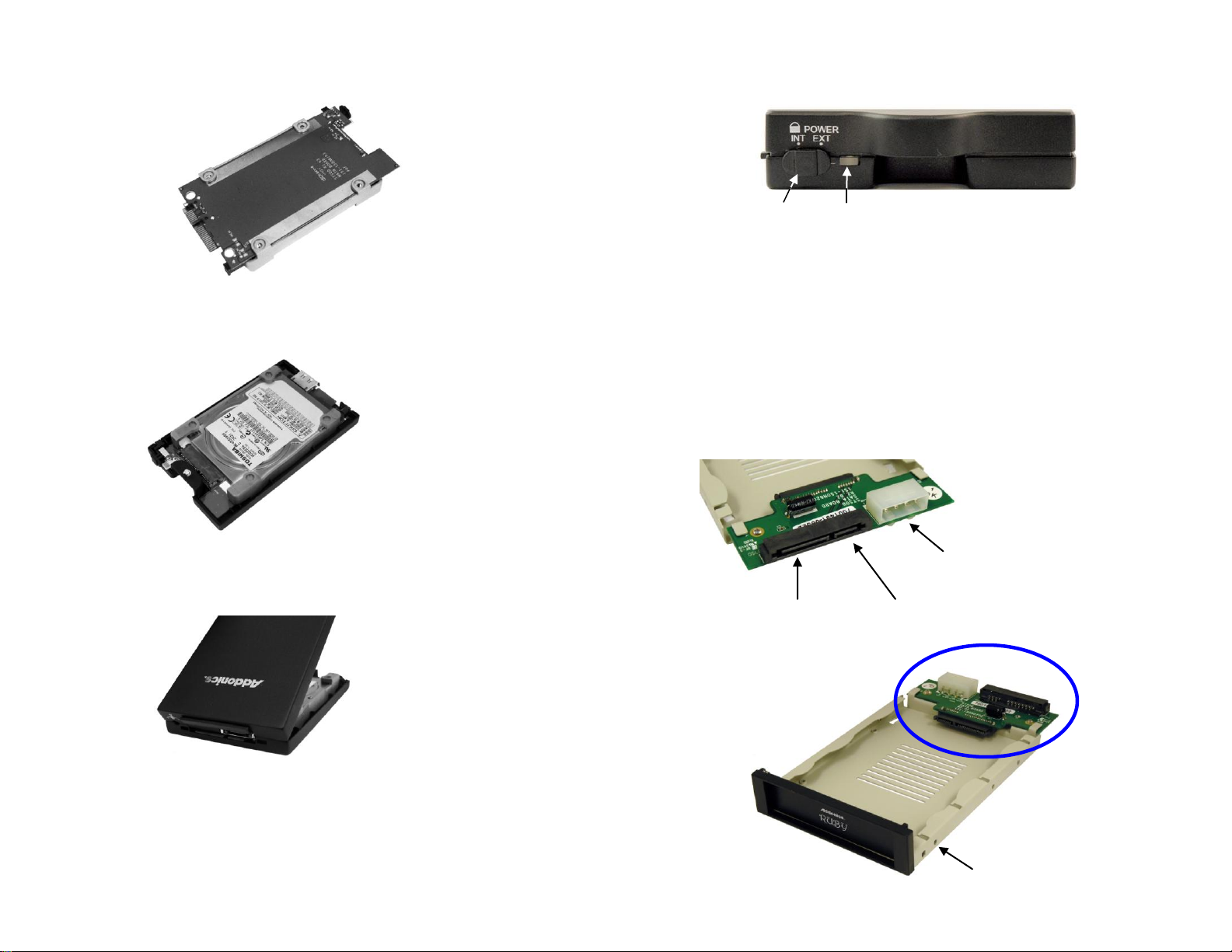
Step 4 Turn over the PCB and secure the hard drive to the PCB with the
Mounting holes for
3 ½” drive bay
15-pin SATA
power connector
4-pin Molex
power connector
Power LED and
Drive Access LED
Switch
7-pin SATA
data connector
mounting screws that come with the kit.
Step 5 Mount the board to the bottom cover.
Step 6 Put the top cover on by holding it in near vertical position and sliding the
two metal clips inside the two small slots on the rear of the bottom cover.
Step 7 Lower the front of the top cover and making sure the two covers lined up
properly. Tighten the small retaining screw on the front of the bottom cover to
close the enclosure.
Ruby Enclosure
Switch:
INT: This mode is used when the enclosure is placed inside a drive
cradle. For mobile rack kits, this is the mode used.
EXT: This mode is used if the enclosure is used as an external hard
drive.
Ruby Drive Cradle
Note: You can only use one power connector at a time. Either use the 4-pin
Molex or 15-pin SATA connector but not simultaneously use them.
Page 3

Model: RCHDSAES
Power adapter
Power adapter
eSATA cable
eSATA cable
USB Port
Green LED showing
adapter connectivity
Red LED showing
adapter access
eSATA cable from
Ruby enclosure
*Note: The Ruby combo hard drive with the eSATA interface must be connected
to a SATA controller with hot swap capability in order to add and remove drive
cartridge without rebooting. Please consult your motherboard or the add-in card
manufacturer to determine hot swap support on your SATA controller. All of the
Addonics SATA Host Controllers are hot swap capable.
For External Application:
Step 1: Connect the eSATA cable to the eSATA port at the back of the
enclosure. The other end of the cable connects to an eSATA host controller.
Step 2: Plug into the power jack located at the back of the enclosure, the power
adapter. This power connection provides power to the ruby enclosure.
Step 3: Set the switch to EXT position. The power LED will light up to indicate
power is provided to the drive.
Model: RCHDSAEU
For External Application:
Step 1: Connect the eSATA cable to the eSATA port at the back of the
enclosure. The other end of the cable connects to the eSATA port on the USB2.0
to eSATA adapter. Plug the adapter to a USB port on your system.
Step 2: Plug into the power jack located at the back of the enclosure, the power
adapter. This power connection provides power to the ruby enclosure.
Step 3: Set the switch to EXT position. The power LED will light up to indicate
power is provided to the drive.
Page 4

For Internal Application: (Applies to both models)
Drive
Drive
Step 1: Connect a SATA cable to the 7-pin SATA data connector to the SATA
interface of the cradle.
Step 2: Connect a 15-pin SATA power cable from your system’s power supply to
the SATA interface of the cradle. This power connection provides power to the
ruby drive cartridge system.
Step 3: Slide the Ruby enclosure inside the cradle. To turn ON the drive
enclosure, place switch on INT position.
Technical Support
If you need assistance to get your unit functioning properly, please call Addonics
Technical Support. Our technical staff will be happy to assist you, but they will
need your help to do so. Calling the technical support staff without all the proper
information can be both time consuming and frustrating. Here are some tips to
help you out:
MODEL NUMBER – Please have this number on hand.
SYSTEM INFORMATION – Type of computer, peripherals, etc.
OPERATING SYSTEM – What version of Windows
WHAT’S THE TROUBLE? – Give enough information
about your problem so that we can recreate and diagnose it.
FREE Software Drivers for all Addonics Technologies
Products are available 24 hours per day at the
World Wide Web Site: www.addonics.com.
Contact Information
Phone: 408-433-3899
Fax: 408-433-3898
Email: http://www.addonics.com/sales/query/
Internet: http://www.addonics.com
TECHNICAL SUPPORT
Phone: 408-433-3855
Hours: 8:30 am - 6:00 pm PST
Email: http://www.addonics.com/support/query/
 Loading...