

Page 1

Addonics
T E C H N O L O G I E S
Diamond Combo Hard Drive
DCHDSAES & DCHDIES
DCHDIEU & DCHDSAEU
User’s Guide
Version 1.0
Page 2
FCC Warning Statement
This equipment has been tested and found to comply with the limits for a class B
digital device pursuant to Part 15 of the FCC rules. These limits are designed to
provide reasonable protection against harmful interference in a residential
installation. This equipment generates, uses and can radiate radio frequency
energy. If not installed and used in accordance with the instructions, it may
cause harmful interference to radio communications. However, there is no
guarantee that interference will not occur in a particular installation. If the
equipment does cause harmful interference to radio or television reception, which
can be determined by turning the equipment on and off, the user is encouraged
to try and correct the interference by one or more of the following suggestions.
Reorient or relocate the receiving antenna
Increase the distance between the equipment and the receiver
Connect the equipment to a different power outlet other than the one where
receiver is connected
Consult a certified television or radio technician
LIMITED WARRANTY
Addonics guarantees that every product is free from physical defects in material
and workmanship during the warranty period specified for each product when used
within the limits set forth in the Specifications section in the user guide.
Unauthorized tampering of the product or using it outside the scope of the
product specifications will result in voiding the warranty. If the product proves
defective during this warranty period, call Addonics Technical Support to obtain a
Return Authorization number. BE SURE TO HAVE YOUR PROOF OF
PURCHASE ON HAND WHEN CALLING. RETURN REQUESTS CANNOT BE
PROCESSED WITHOUT PROOF OF PURCHASE. When returning a product,
mark the Return Authorization number clearly on the outside of the package and
include your original proof of purchase. Customers are responsible for paying the
shipping and handling of the products to Addonics warranty service location.
IN NO EVENT SHALL ADDONICS’ LIABILITY EXCEED THE PRICE PAID FOR
THE PRODUCT FROM DIRECT, INDIRECT, SPECIAL, INCIDENTAL, OR
CONSEQUENTIAL DAMAGES RESULTING FROM THE USE OF THE
PRODUCT, ITS ACCOMPANYING SOFTWARE, OR ITS DOCUMENTATION.
Addonics makes no warranty or representation, expressed, implied, or statuary,
with respect to its products or the contents or use of the user guide and all
accompanying software, and specifically disclaims its quality, performance,
merchantability, or fitness for any particular purpose. Addonics reserves the right
to revise or update its products, software, or documentation without obligation to
notify any individual or entity.
Hardware Installation Guide
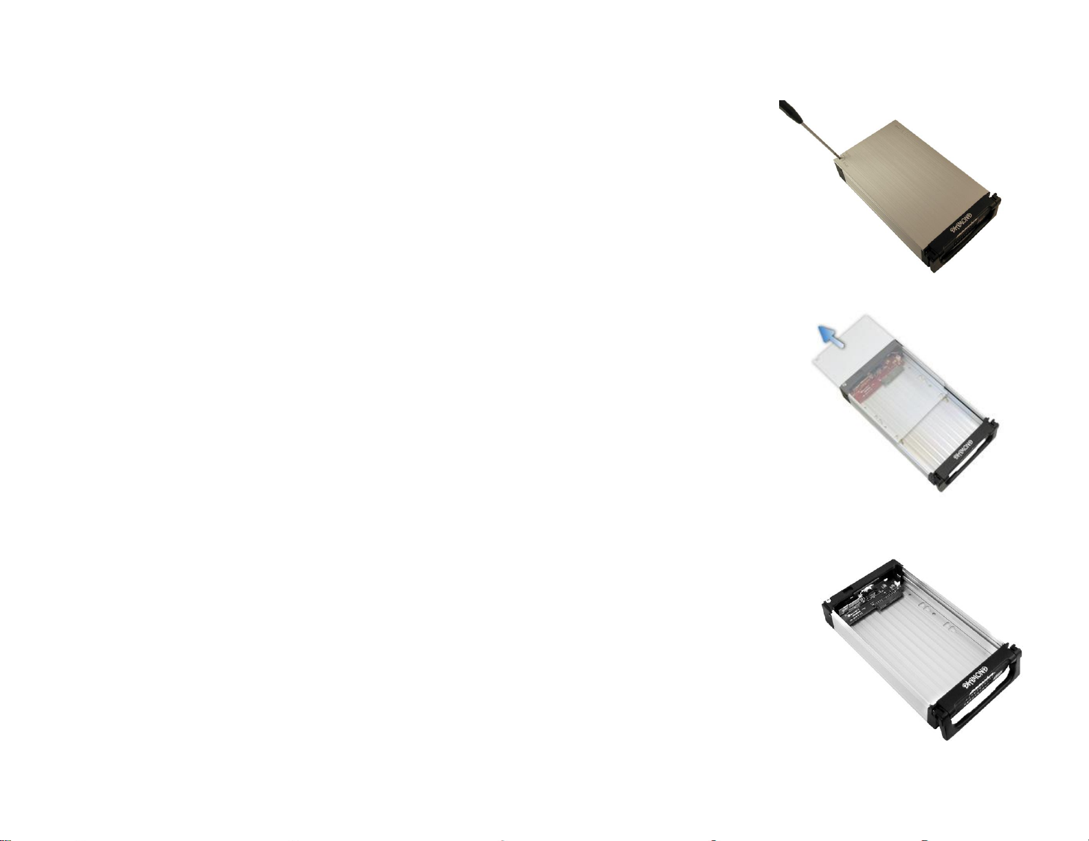
Step 1
Use a Philips screwdriver to
turn the cover securing
screw into the “OPEN”
position.
Step 2
Slide the aluminum cover
towards the back end of the
Diamond and remove it.
Step 3
For SATA Drive
Carefully place the SATA hard drive
with the label facing up into the
Diamond enclosure. Push the hard
drive towards the back end to secure
the drive connectors onto the
Diamond enclosure’s SATA
connector.
Page 3

eSATA
connector
On / OFF
switch
Mini-Din power
connector
For IDE Drive
Note: Set up your IDE hard drive
as Master device
Connect the 4-Pin Molex cable to
the power connector on the IDE
hard drive. Carefully place the IDE
hard drive with the label facing up
into the Diamond enclosure. Push
the hard drive towards the back end
to secure the drive connectors onto
the Diamond enclosure’s IDE
connector.
Step 4
Turn the Diamond enclosure over
with the hard drive mounting holes
facing up. Use the included flat
head screws to secure the hard
drive onto the bottom of the
enclosure and turn in the screw to
the “LOCK” position.
Cable Connections
Power: Connect the 6-pin Mini DIN power cable (provided) to the 6-pin
Mini DIN power connector located at the back of the enclosure.
Data:
Model: DCHDSAES & DCHDIES
Connect the eSATA to eSATA cable to the eSATA connector located at
the back of the enclosure and the other end of the eSATA cable to the
eSATA connector on your SATA host controller with eSATA ports.
Model: DCHDSAEU & DCHDIEU
Connect the eSATA to eSATA cable to the eSATA connector located at
the back of the enclosure and the other end of the eSATA cable to the
eSATA connector on the USB2.0 to eSATA adapter. You can now plug
the adapter to a USB port on your system.
Powering On Enclosure: To power on the enclosure, move the switch
located at the back of the enclosure to the ON mode. When the switch is
turned on, the LED light beside it would light up to indicate power and
also drive access.
Note: There are no drivers needed to use the eSATA cable as long
as the drivers are installed for the Serial ATA Controller card/chip. It
is plug and play.
Page 4

Power & Drive
Activity LED
Key Lock Switch
SATA data
connector
LED DISPLAY Switch
LEFT – LED signal from drive
RIGHT – LED signal from controller
SATA power
connector
Cable Connections When Used as an Internal Hard Drive
Power: Use either the 4-pin Molex or the 15-pin SATA power connector.
Do not use both power sources simultaneously.
Data:
Connect the SATA cable to the SATA connector located at the back of the drive
cradle and the other end to the SATA connector on your SATA host controller or
onboard SATA port.
LED cable: Only needed if you want to get drive access signal from the SATA
controller. Use the LED cable to connect the LED pin located at the back of the
cradle (beside the LED switch) to the LED jumper pins on your SATA host
controller or onboard SATA port to enable the drive activity LED.
Factory default, LED signal coming from hard drive.
Powering On Drive Cradle: To power on the drive cradle, slide in the Diamond
cartridge and using the key (supplied), turn the cradle lock located at the front of
the cradle to the LOCK position. This will provide power as indicated by the
green LED lighting up and secure the cartridge.
Technical Support
If you need assistance to get your unit functioning properly, please call Addonics
Technical Support. Our technical staff will be happy to assist you, but they will
need your help to do so. Calling the technical support staff without all the proper
information can be both time consuming and frustrating. Here are some tips to
help you out:
MODEL NUMBER – Please have this number on hand.
SYSTEM INFORMATION – Type of computer, peripherals, etc.
OPERATING SYSTEM – What version of Windows
WHAT’S THE TROUBLE? – Give enough information
about your problem so that we can recreate and diagnose it.
FREE Software Drivers for all Addonics Technologies
Products are available 24 hours per day at the
World Wide Web Site: www.addonics.com.
Contact Information
Phone: 408-433-3899
Fax: 408-433-3898
Email: http://www.addonics.com/sales/query/
Internet: http://www.addonics.com
TECHNICAL SUPPORT
Phone: 408-433-3855
Hours: 8:30 am - 6:00 pm PST
Email: http://www.addonics.com/support/query/
 Loading...