

Page 1

NWAR3600
ADSL 11n Gateway
User’s Manual
Version 0.1
Copyright © 2008
Page 2

Manual Ver2.0
Table of Contents
1. INTRODUCTION.....................................................................................................................................................4
1.1 FEATURES.........................................................................................................................................................4
1.2 SYSTEM REQUIREMENTS ..................................................................................................................................4
2. INSTALLATION....................................................................................................................................................... 5
FRONT PANEL ................................................................................................................................................................. 5
REAR PANEL ...................................................................................................................................................................5
CONNECTING THE HARDWARE........................................................................................................................................6
Step 1. Connect the ADSL cable and optional telephone.......................................................................................... 6
Step 2. Connect the Ethernet cable............................................................................................................................6
Step 3. Attach the power connector........................................................................................................................... 6
Step 4. Turn on NWAR3600 and power up your systems........................................................................................... 7
Step 5. Configure NWAR3600 through the WEB interface........................................................................................7
Step 6. Save the configurations and Reboot..............................................................................................................7
3. CONFIGURATION..................................................................................................................................................8
3.1 SETUP...............................................................................................................................................................8
3.2 ESTABLISH THE CONNECTION .......................................................................................................................... 8
4. QUICK SETUP.......................................................................................................................................................10
4.1 PPP OVER ETHERNET (PPPOE) CONFIGURATION............................................................................................ 11
4.2 IP OVER ATM (IPOA) CONFIGURATION..........................................................................................................15
4.3 BRIDGE CONFIGURATION................................................................................................................................19
4.4 MAC ENCAPSULATION ROUTING (MER) CONFIGURATION............................................................................22
4.5 PPP OVER ATM (PPPOA) CONFIGURATION.................................................................................................... 23
5. ADVANCED SETUP ..............................................................................................................................................24
5.1 WAN..............................................................................................................................................................24
5.2 LAN ............................................................................................................................................................... 24
5.3 NAT...............................................................................................................................................................25
5.4 SECURITY.......................................................................................................................................................30
5.5 PARENTAL CONTROL ......................................................................................................................................31
5.6 QUALITY OF SERVICE ..................................................................................................................................... 32
5.7 ROUTING ........................................................................................................................................................35
5.8 DNS...............................................................................................................................................................38
5.9 DSL ...............................................................................................................................................................40
5.10 INTERFACE GROUP .........................................................................................................................................41
5.11 CERTIFICATE...................................................................................................................................................43
- 2 -
Page 3

Manual Ver2.0
6. WIRELESS SETUP................................................................................................................................................46
6.1 BASIC ............................................................................................................................................................. 46
6.2 SECURITY.......................................................................................................................................................46
6.3 MAC FILTER..................................................................................................................................................50
6.4 WIRELESS BRIDGE..........................................................................................................................................50
6.5 ADVANCED.....................................................................................................................................................51
6.6 STATION INFO .................................................................................................................................................53
7. DIAGNOSTICS.......................................................................................................................................................54
8. MANAGEMENT ....................................................................................................................................................55
8.1 SETTINGS........................................................................................................................................................55
8.2 SYSTEM LOG ..................................................................................................................................................57
8.3 TR-069 CLIENT .............................................................................................................................................. 58
8.4 INTERNET TIME ..............................................................................................................................................59
8.5 ACCESS CONTROL .......................................................................................................................................... 60
8.6 UPDATE SOFTWARE........................................................................................................................................62
8.7 SAVE/REBOOT ................................................................................................................................................62
9. DEVICE INFO........................................................................................................................................................63
9.1 SUMMARY ......................................................................................................................................................63
9.2 WAN..............................................................................................................................................................63
9.3 STATISTICS .....................................................................................................................................................63
9.4 ROUTE............................................................................................................................................................65
9.5 ARP...............................................................................................................................................................66
9.6 DHCP ............................................................................................................................................................66
- 3 -
Page 4

Manual Ver2.0
1. Introduction
Congratulations on becoming the owner of NWAR3600 gateway. You will now be able to
access the Internet and telephony service using your high-speed ADSL connection.
NWAR3600 has the following major features.
1.1 Features
• Built-in ADSL modem for high speed Internet access
• Network Address Translation (NA T) and IP filtering functions to provide
network sharing and firewall protection for your computers
• IEEE 802.11n 270Mbps Access Point
This User’s Manual will guide you to install and configure your NWAR3600.
1.2 System Requirements
Before installing your NWAR3600, make sure that you have the following:
• ADSL service up and running on your telephone line, with at least one public Internet
address for your LAN
• One or more computers each containing an Ethernet 10Base-T/100Base-T network
interface card (NIC) or wireless network adapter.
For system configuration, use the supplied web-based program.
Note: Make sure that your computer has a web browser such as Internet Explorer v5.0 or
later, or Netscape v4.7 or later.
- 4 -
Page 5
Manual Ver2.0
2. Inst allation
In addition to this document, your NWAR3600 should arrive with the following:
One standalone desktop NWAR3600
One power adapter and power cord
One Ethernet cable with RJ-45 connector
One telephone cable with RJ-11 connector
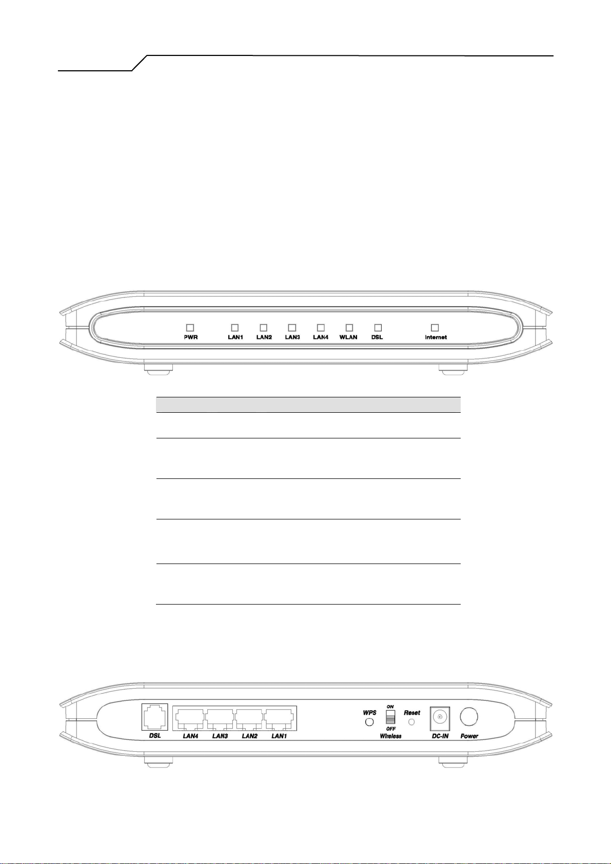
Front Panel
The front panel LEDs indicates the status of the unit.
Label Color Function
PWR
LAN 1~4
WLAN
DSL
Internet
Green
Green
Green
Green Flashes during the training mode.
Green
On: Power is on
Off: Power is off
On: LAN link established and active
Off: No LAN link
Flashes during data transfer
On: WLAN enabled
Off: WLAN disabled
Flashes during data transfer
On: ADSL link is established and active
Off: no ADSL connection availabl e
On: Connection to the ISP is es tabl ished
Off: No connection to the ISP
Flashes during data transfer
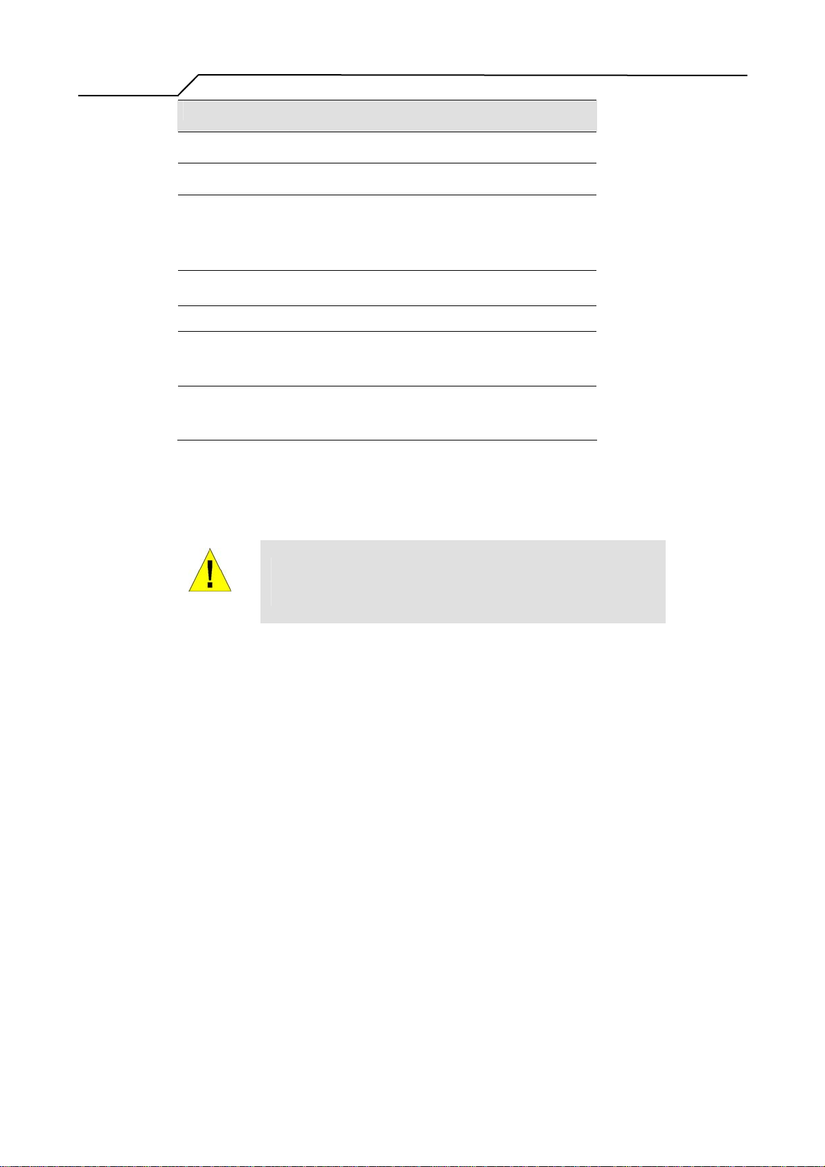
Rear Panel
The connectors located at the rear panel have the following functions (from right to left).
- 5 -
Page 6
Manual Ver2.0
Interface Function
Power Button Switch power on (up)/ off (down)
Power Jack Connects to the supplied pow er ad apter cable
Reset
Wireless switch Switch wireless on / off
WPS WPS push button
LAN 1~4
DSL
Press the reset button for 2 s econds and th en re lease;
the router will be res tar ted (reb ooted). Press for more
than 5 seconds to reset to factory default settings.
RJ-45 connector: connects to PC's Ethernet por t, or to
the uplink port of switch/hub
RJ-11 connector: connects to splitter terminal
(Modem)
Connecting the Hardware
Connect NWAR3600 to the phone jack, the power outlet, and your computer or network.
Before you begin, turn the power off for all devices. These include your
computer(s), your LAN hub/switch (if applicable), and NWAR3600.
WARNING
Step 1. Connect the ADSL cable and optional telephone
Connect one end of the phone cable to the ADSL connector on the rear panel of NWAR3600.
Connect the other end to the ADSL outlet provided by your service provider (normally MODEM
port of the attached splitter).
Step 2. Connect the Ethernet cable
Connect one end of the Ethernet cable to the one of the four RJ-45 connectors (LAN1 ~ LAN4) on
the rear panel of NWAR3600 and connect the other end to your PC’s network adaptor (NIC). If you
are connecting a LAN to NWAR3600, attach one end of the Ethernet cable to a regular hub port and
the other end to the LAN port on NWAR3600.
Step 3. Attach the power connector
Connect the AC power adapter to the power connector on NWAR3600 and plug in the adapter to a
- 6 -
Page 7

Manual Ver2.0
wall outlet or power extension.
Step 4. Turn on NWAR3600 and power up your systems
Press the Power switch on the back panel of NWAR3600 to the ON (UP) position.
Turn on and boot up your computer(s) and any LAN devices such as hubs or switches.
Step 5. Configure NWAR3600 through the WEB interface
Please refer to chapter 3.
Step 6. Save the configurations and Reboot
Save the changes you made on NWAR3600.
- 7 -
Page 8
Manual Ver2.0
3. Configuration
3.1 Setup
z Connect NWAR3600 and PC with an RJ-45 Ethernet cable.
z Turn on NWAR3600.
z The default IP address of NWAR3600 is 192.168.1.1.
3.2 Establish The Connection
z Enter the IP address (default: 192.168.1.1) of NWAR3600 in the address line of
Web Browser
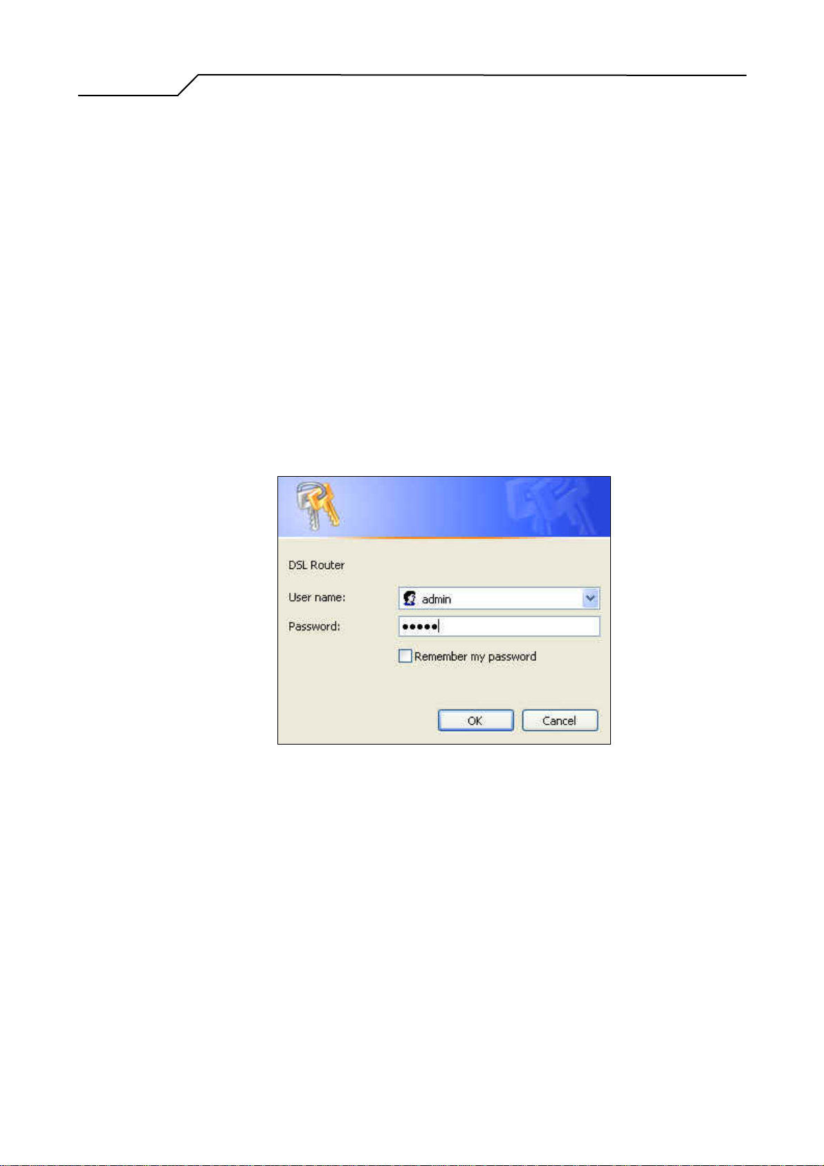
z A Dialogue Box will pop up to request the user to login. (Figure 2)
Figure 2. Authentication
z Please enter the management username/password into the fields then click on the
OK button (default username/password is admin/admin).
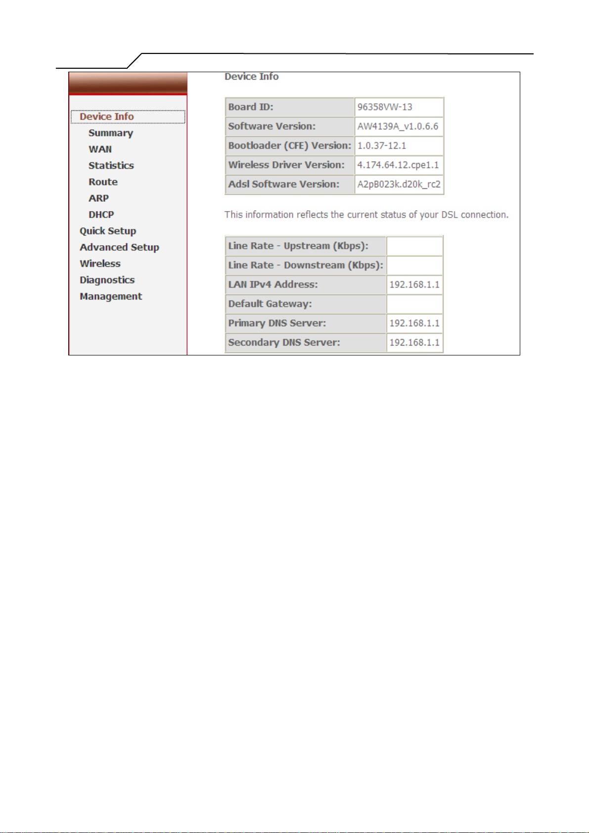
z If the authentication is valid, the home page “Device Info - Summary” will be
displayed on the screen. (Figure 3)
- 8 -
Page 9
Manual Ver2.0
Figure 3. NWAR3600 Device Info Page
- 9 -
Page 10
Manual Ver2.0
4. Quick Setup
The system administrator can configure NWAR3600 remotely or locally via a Web Browser.
Network configuration needs to be planned and decided before starting the configuration procedure.
Quick Setup allows system administrator to select the appropriate operation mode and configure the
corresponding settings step by step to create a connection. The following five operation modes are
supported:
• PPP over Ethernet (PPPoE)
• IP over ATM (IPoA)
• Bridging
• MAC Encapsulation Routing (MER)
• PPP over ATM (PPPoA)
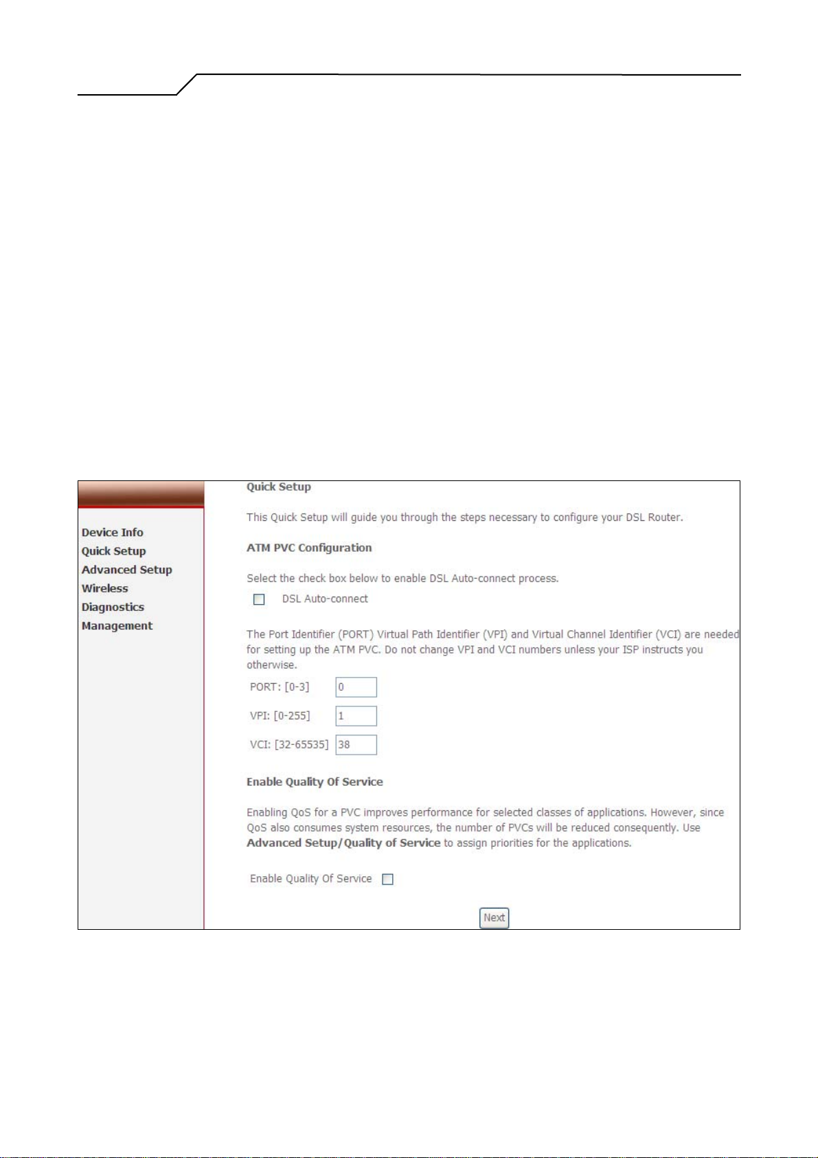
ATM PVC and QoS Configuration
Figure 4. Quick Setup – ATM PVC and QoS Configuration
Enter the VPI/VCI values. Please contact you ISP for the information.
- 10 -
Page 11
Manual Ver2.0
Check “Enable Quality of Service” for upstream traffic QoS.
Go to “Advanced Setup” > “Quality of Service” to configure QoS rules.
Click on “Next” to go to next step.
4.1 PPP over Ethernet (PPPoE) Configuration
After ATM PVC and QoS Configuration, follow the steps below to create a PPP over
Ethernet (PPPoE) connection.
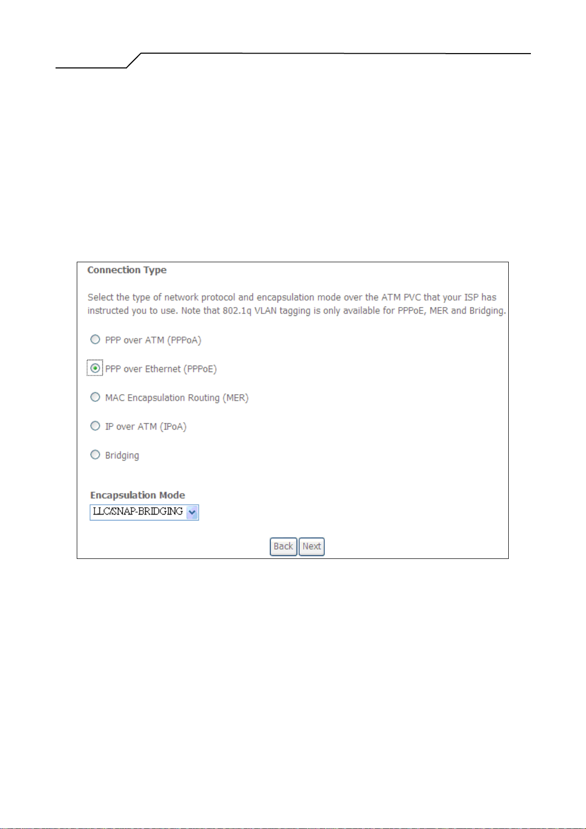
4.1.1 Connection Type and Encapsulation Mode
Figure 5. Quick Setup – Connection Type and Encapsulation Mode
Select “PPP over Ethernet (PPPoE) and the “Encapsulation Mode”. Please contact
you ISP for the information.
Click on “Next” to go to next step.
4.1.2 PPP Username and Password
- 11 -
Page 12
Manual Ver2.0
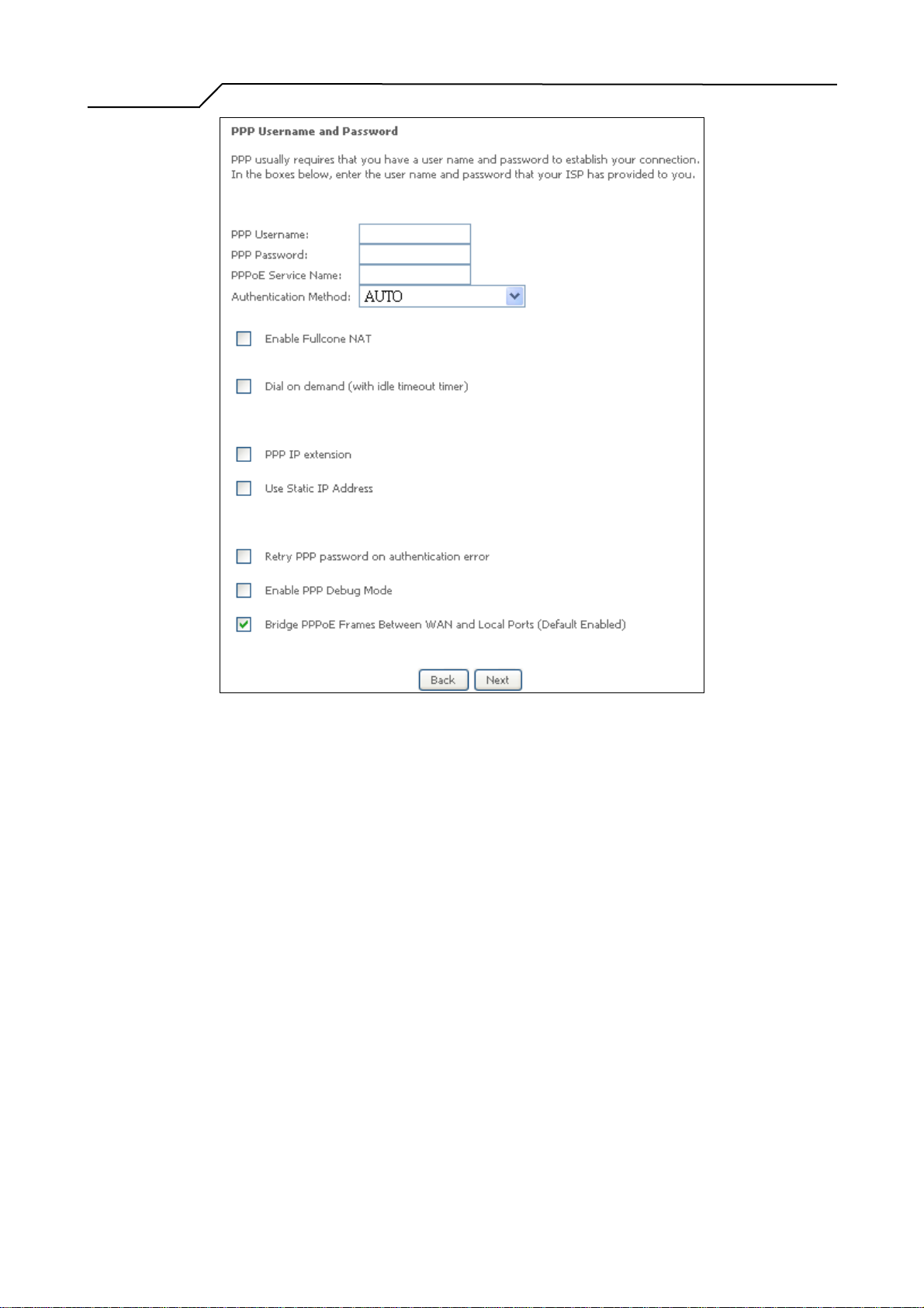
Figure 6. Quick Setup – PPP Username and Password
Enter “PPP Username”, “PPP Password”, and select “Authentication Method”
(AUTO/PAP/CHAP). Please contact you ISP for the information.
The “Dial on demand” function, if checked, will tear down the PPP link
automatically when there is no outgoing packet for the programmed period of time
that is set below.
NWAR3600 activates PPPoE connection automatically when user wants to access
Internet and there is no active PPPoE connection.
“PPP IP extension” allows NWAR3600 to pass the obtained IP address to the local
PC and act as a bridge only modem.
Select “Use Static IP Address” and type in the IP address given by your ISP in this
field if your NWAR3600’s IP address is not dynamically assigned.
“Enable PPP Debug Mode “allows users to see the PPP authentication process
from NWAR3600’s System Log.
- 12 -
Page 13
Manual Ver2.0
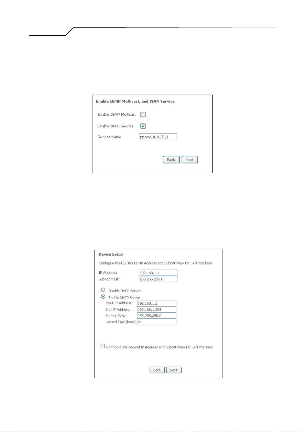
4.1.3 IGMP Multicast, WAN service
The users are able to assign some specific ATM PVC(s) to run PPPoE, if
NWAR3600 has multiple ATM PVC connections.
Click on “Next” to go to next step.
Figure 7. Quick Setup – IGMP Multicast, WAN service
Check to Disable/Enable IGMP Multicast and WAN Service.
Click on “Next” to go to next step.
4.1.4 Device Setup
Figure 8. Quick Setup – Device Setup
- 13 -
Page 14
Manual Ver2.0
Enter IP (LAN IP) and Subnet Mask.
Select to Disable/Enable DHCP Server, use DHCP Server Relay, and configure
related settings for that mode.
NWAR3600 will assign IP address, subnet mask, Default gateway IP address and
DNS server IP address to host PCs which connect to its LAN.
Select “Configure the second IP Address and Subnet Mask for LAN interface” and
configure if second IP Address is used.
Note: Network Address Translation function (NAT) is default enabled and is not
showing on the page to prevent it from being disabled.
Click on “Next” to go to next step.
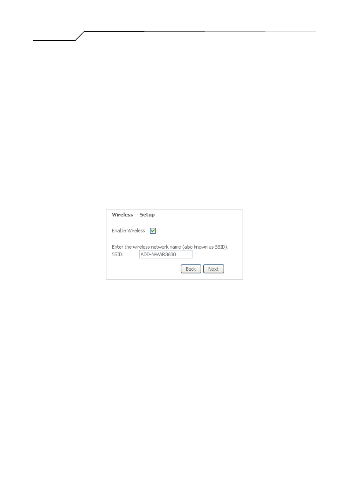
4.1.5 Wireless Setup
Check “Enable Wireless” to enable wireless radio; or uncheck to disable.
“SSID” is the network name shared among all devices in a wireless network. It is
case-sensitive and must not exceed 32 alphanumeric characters.
Click on “Next” to go to next step.
Figure 9. Quick Setup - Wireless Setup
4.1.6 WAN Setup – Summary
- 14 -
Page 15

Manual Ver2.0
Figure 10. Quick Setup – WAN Setup – Summary
The last page displays a summary of previous settings. Make sure that the
configurations match the settings provided by ISP, and then click on
“Save/Reboot” button to complete the configuration procedure.
4.2 IP over ATM (IPoA) Configuration
After ATM PVC setting, follow the steps below to create an IP over ATM (Routed)
connection.
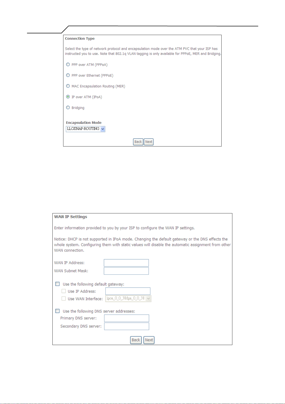
4.2.1 Connection T ype
- 15 -
Page 16
Manual Ver2.0
Figure 11. Quick Setup – Connection Type and Encapsulation Mode
Select “IP over ATM (IPoA) and the “Encapsulation Mode”. Please contact you
ISP for the information. Click on “Next” to go to next step.
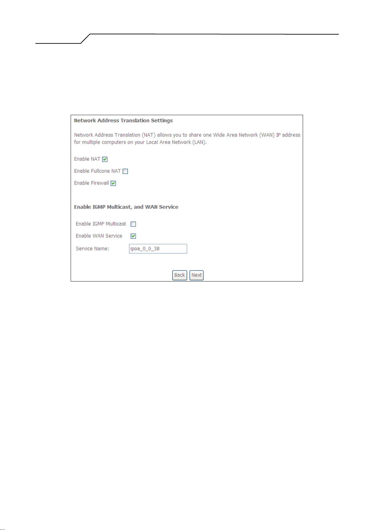
4.2.2 WAN IP Settings
Figure 12. Quick Setup– WAN IP Settings
- 16 -
Page 17
Manual Ver2.0
4.2.3 NAT, Firewall, IGMP Multicast and WAN Service
WAN IP/Subnet Mask, default gateway, and DNS server settings. Please contact
your ISP for the information. Click on “Next” to go to next step.
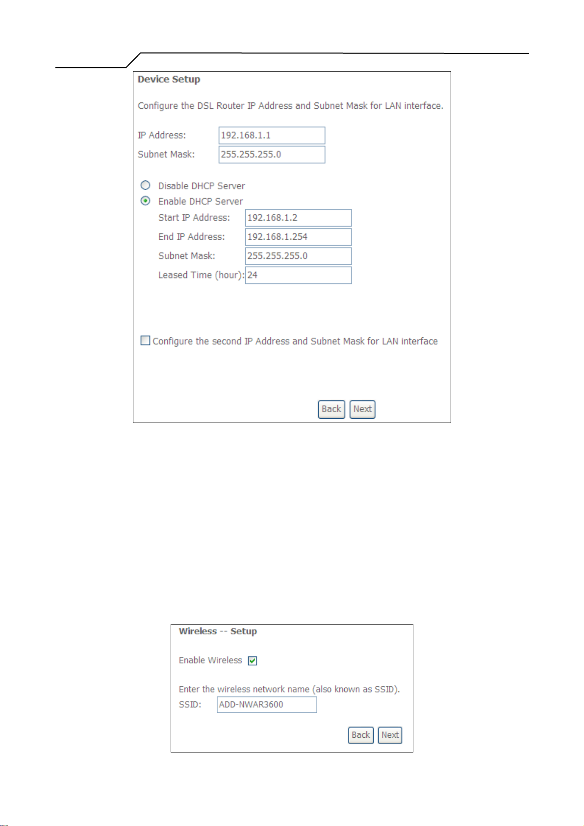
Check to Enable/Disable NAT and Firewall functions.
Go to “Advanced Setup” > “Firewall” to assign filter rules.
Check to Enable/Disable IGMP Multicast and WAN Service.
Click on “Next” to go to next step.
4.2.4 Device Setup
Figure 13. Quick Setup – IPoA – NAT, IGMP Multicast and WAN service
- 17 -
Page 18
Manual Ver2.0
Figure 14. Quick Setup – Device Setup
Enter IP (LAN IP) Address and Subnet Mask to NWAR3600.
Select to Disable/Enable DHCP Server, use DHCP Server Relay, and configure
related settings for that mode.
Select “Configure the second IP Address and Subnet Mask for LAN interface” and
configure if second IP Address is used.Click on “Next” to go to next step.
4.2.5 Wireless Setup
- 18 -
Page 19
Manual Ver2.0
4.2.6 WAN Setup – Summary
Figure 15. Quick Setup – Wireless Setup
Check “Enable Wireless” to enable wireless radio; or uncheck to disable.
“SSID” is the network name shared among all devices in a wireless network. It
is case-sensitive and must not exceed 32 alphanumeric characters.
Click on “Next” to go to next step.
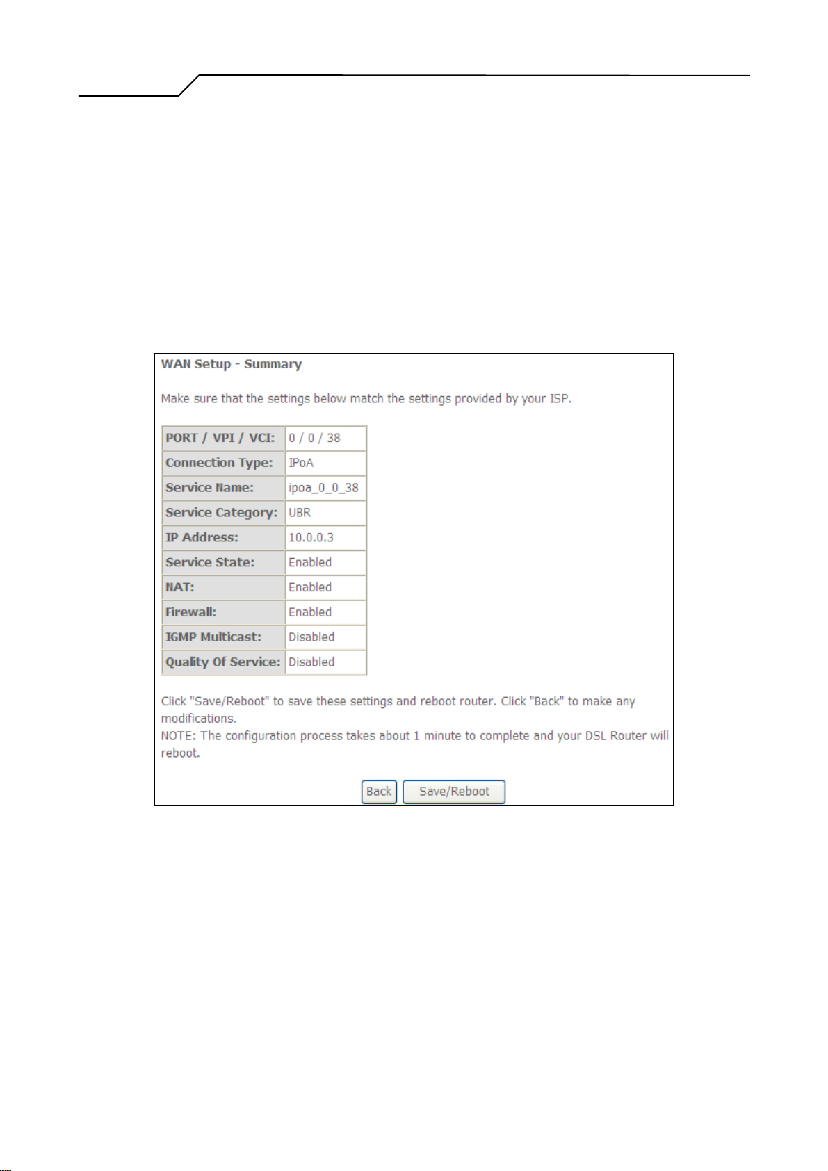
Figure 16. Quick Setup – WAN Setup – Summary
The last page gives a summary of previous steps. Make sure that the settings
match the settings provided by ISP, and then click on “Save/Reboot” button to
complete the configuration procedure.
4.3 Bridge Configuration
After ATM PVC setting, follow the steps below to create a Bridging connection.
- 19 -
Page 20
Manual Ver2.0
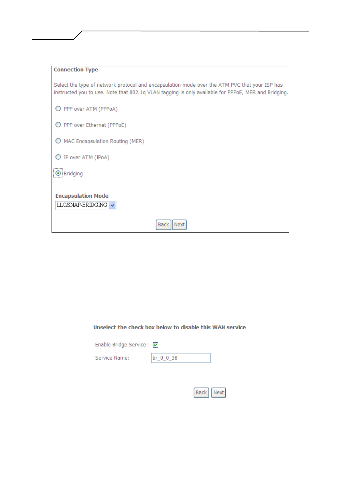
4.3.1 Connection T ype
Figure 17. Quick Setup – Connection Type and Encapsulation Mode
Select “Bridging”, and the “Encapsulation Mode”. Please contact you ISP for the
information. Click on “Next” to go to next step.
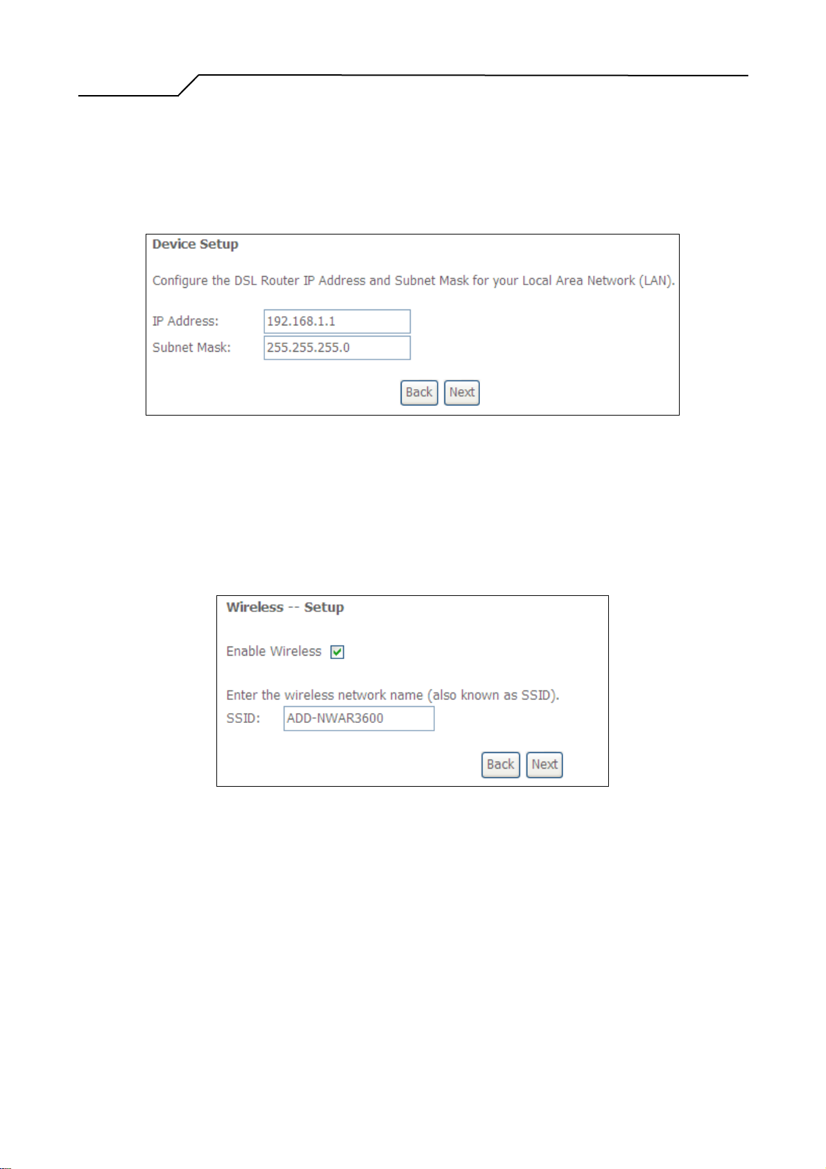
4.3.2 WAN Service
Figure 18. Quick Setup – WAN Service
- 20 -
Page 21
Manual Ver2.0
4.3.3 Device Setup
Give a service name and check the box to enable this WAN service.
Click on “Next” to go to next step.
Figure 19. Quick Setup – Device Setup
Type LAN IP Address and Subnet Mask. Click on “Next” to go to next step.
4.3.4 Wireless Setup
Figure 20. Quick Setup – Wireless Setup
Check “Enable Wireless” to enable wireless radio; or uncheck to disable.
“SSID” is the network name shared among all devices in a wireless network. It
is case-sensitive and must not exceed 32 alphanumeric characters.
Click on “Next” to go to next step.
4.3.5 WAN Setup – Summary
- 21 -
Page 22
Manual Ver2.0
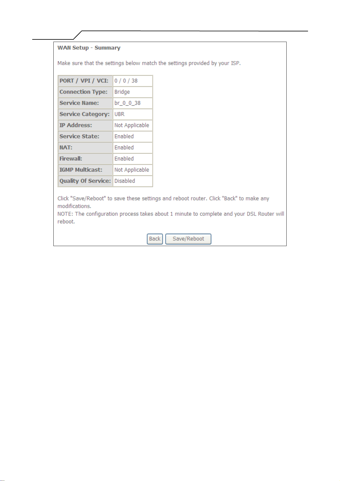
Figure 21. Quick Setup – WAN Setup – Summary
4.3.6
The last page gives a summary of previous steps. Make sure that the settings
match the settings provided by ISP, and then click on “Save/Reboot” button to
complete the configuration procedure.
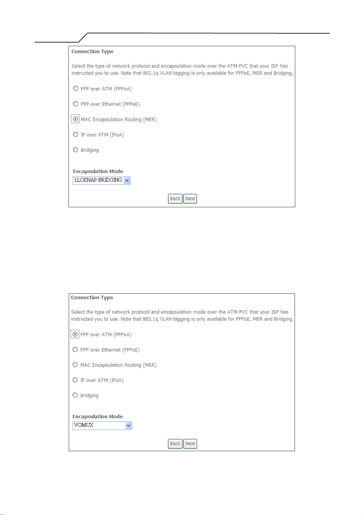
4.4 MAC Encapsulation Routing (MER) Configuration
Configuration of MER is similar to IPoA. Select “MAC Encapsulation Routing
(MER)” in “Connection Type”. For rest of the configurations, please refer to IPoA
settings (section 4.2).
- 22 -
Page 23
Manual Ver2.0
Figure 22. Quick Setup – Connection Type and Encapsulation Mode
4.5 PPP over ATM (PPPoA) Configuration
Configuration of PPPoA is similar to PPPoE. Select “PPP over ATM (PPPoA)” in
“Connection Type”. For rest of the configuration, please refer to PPPoE settings
(section 4.1).
Figure 23. Quick Setup – Connection Type and Encapsulation Mode
- 23 -
Page 24
Manual Ver2.0
5. Advanced Setup
Advanced Setup allows system administrator to configure the following topics:
z WAN
z LAN
z NAT
z Security
z Quality of Service
z Routing
z DSL
z Interface Group
5.1 WAN
z Certificate
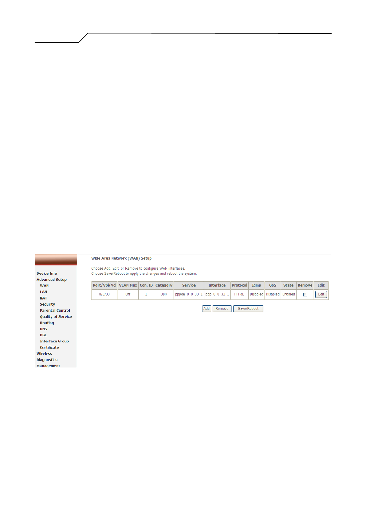
Figure 24. Advanced Setup – WAN
This page shows the current existing WAN interfaces in the system. User can choose
Add, Edit, or Remove to configure WAN interfaces. For detail about Add and Edit
procedure, please refer to 4. Quick Setup.
5.2 LAN
- 24 -
Page 25
Manual Ver2.0
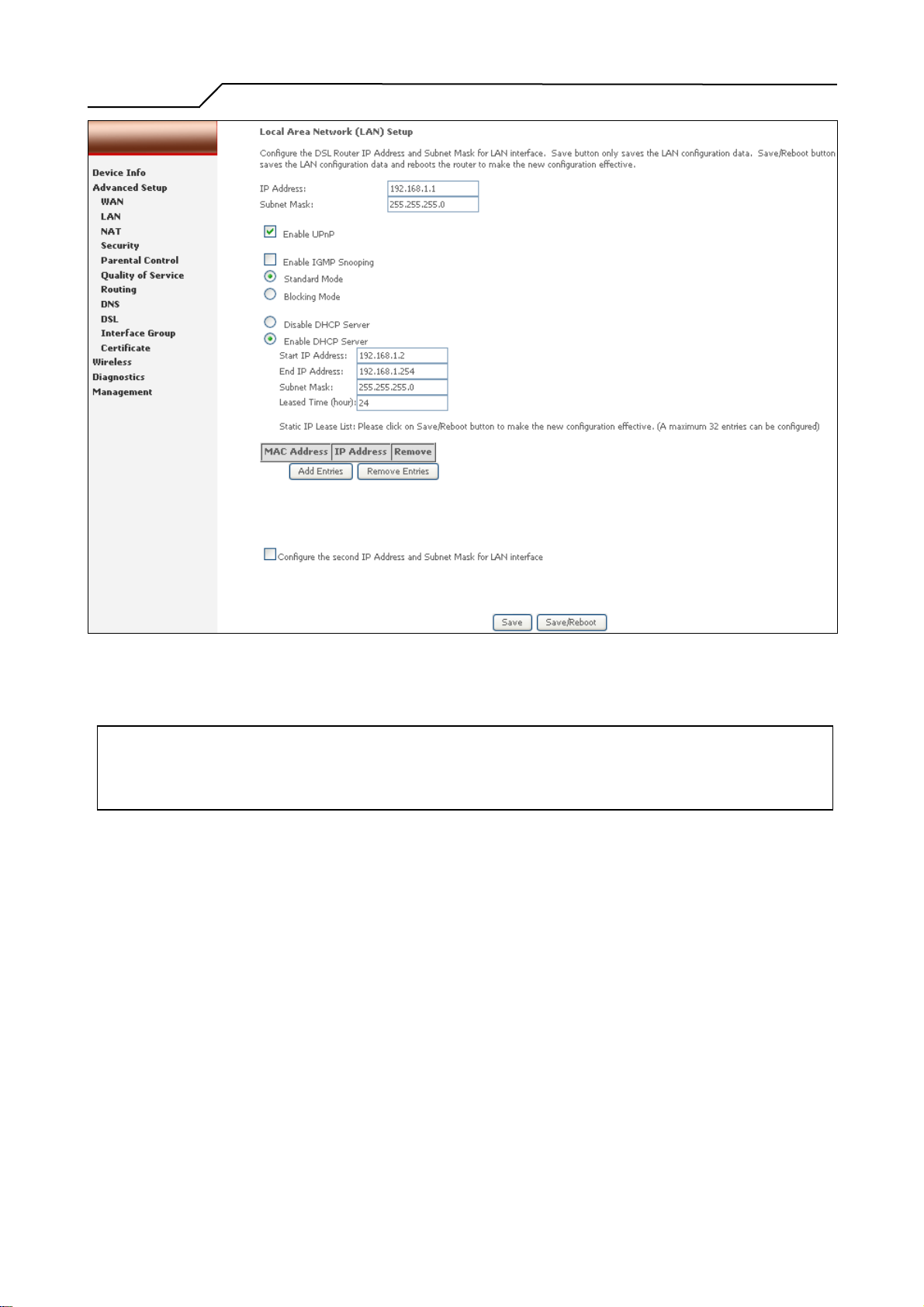
Figure 25. Advanced Setup – LAN
Please refer to 4.1.5.
Note: To utilize DHCP relay function, you need to configure WAN protocol as IPoA or MER
and NAT must be disabled.
5.3 NAT
Three functions are supported in NAT: Virtual Servers, Port Triggering, and DMZ
Host.
5.3.1 Virtual Servers
- 25 -
Page 26
Manual Ver2.0
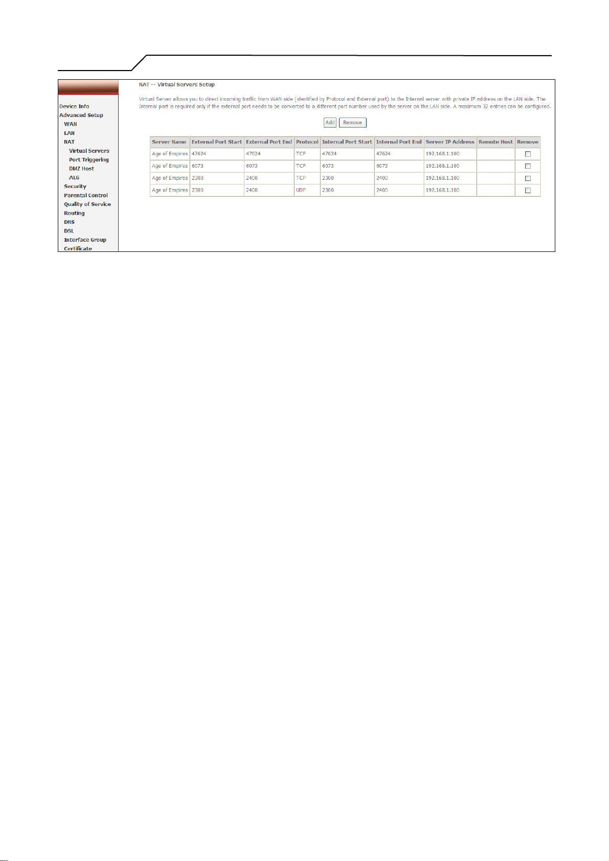
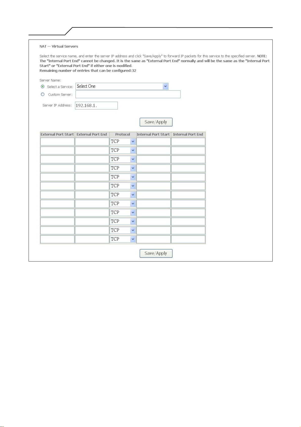
Figure 26. Advanced Setup – NAT
Virtual Server allows you to direct incoming traffic from WAN side (identified by
Protocol and External port) to the internal server with private IP address on the
LAN side. The Internal port is required only if the external port needs to be
converted to a different port number used by the server on the LAN side.
Maximum 32 entries can be configured.
Click on “Add” to enter configuration page to add your own rule(s). Some
common used servers (Web, FTP, Mail …etc.) are pre-defined in NWAR3600.
User can simply select the desired server from the pull-down menu and assign the
IP address of the local PC.
To delete the configured rule(s), check the “Remove” box of the specific rule(s)
and click on “Remove”.
- 26 -
Page 27
Manual Ver2.0
Figure 27. Advanced Setup – NAT – Virtual Servers
5.3.2 Port Triggering
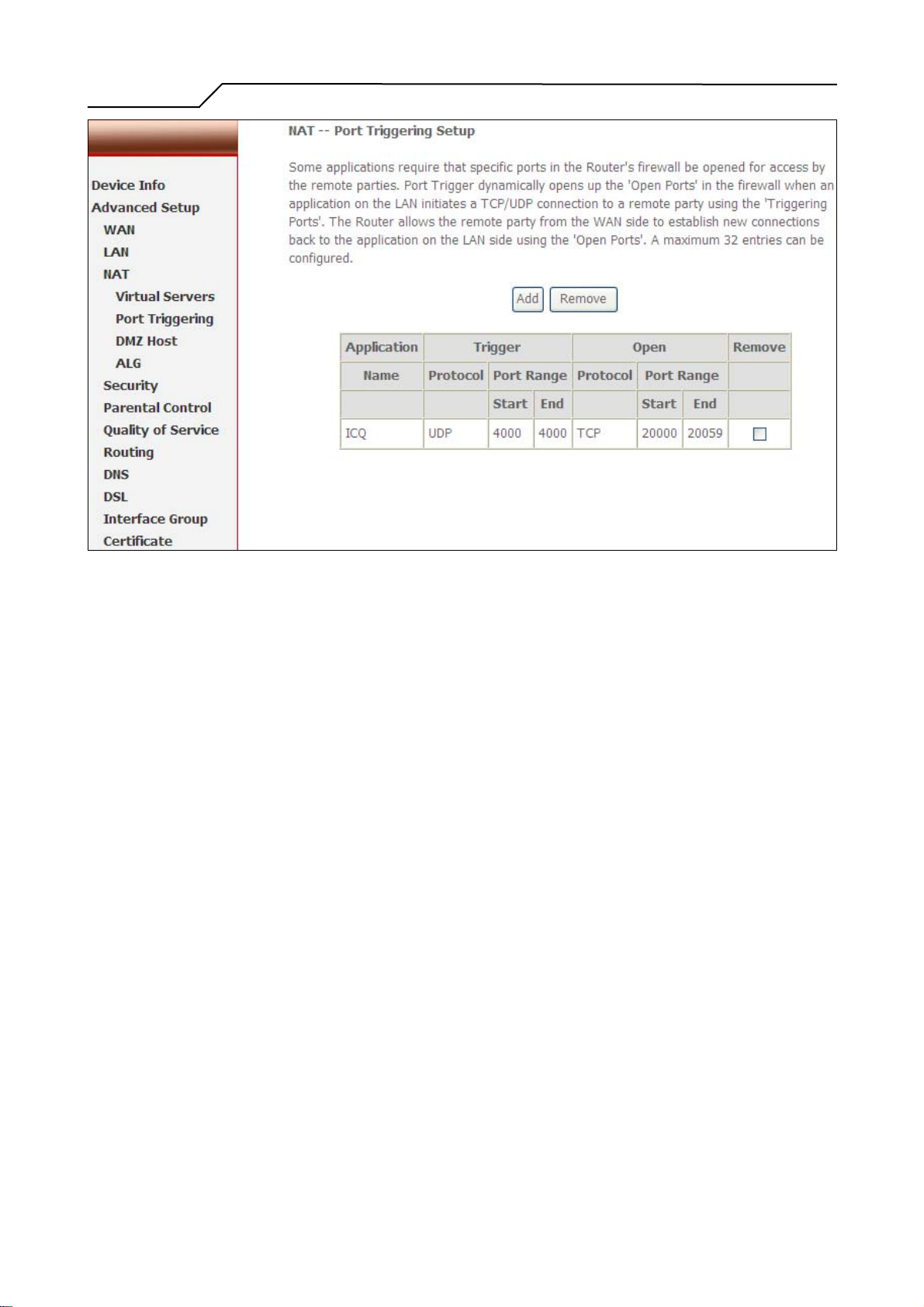
Some applications require that specific ports in the Router's firewall be opened for
access by the remote parties. Port Trigger dynamically opens up the “Open Ports”
in the firewall when an application on the LAN initiates a TCP/UDP connection to
a remote party using the “Triggering Ports”. The Router allows the remote party
from the WAN side to establish new connections back to the application on the
LAN side using the “Open Ports”. A maximum 32 entries can be configured.
- 27 -
Page 28
Manual Ver2.0
Figure 28. Advanced Setup – NAT – Port Triggering
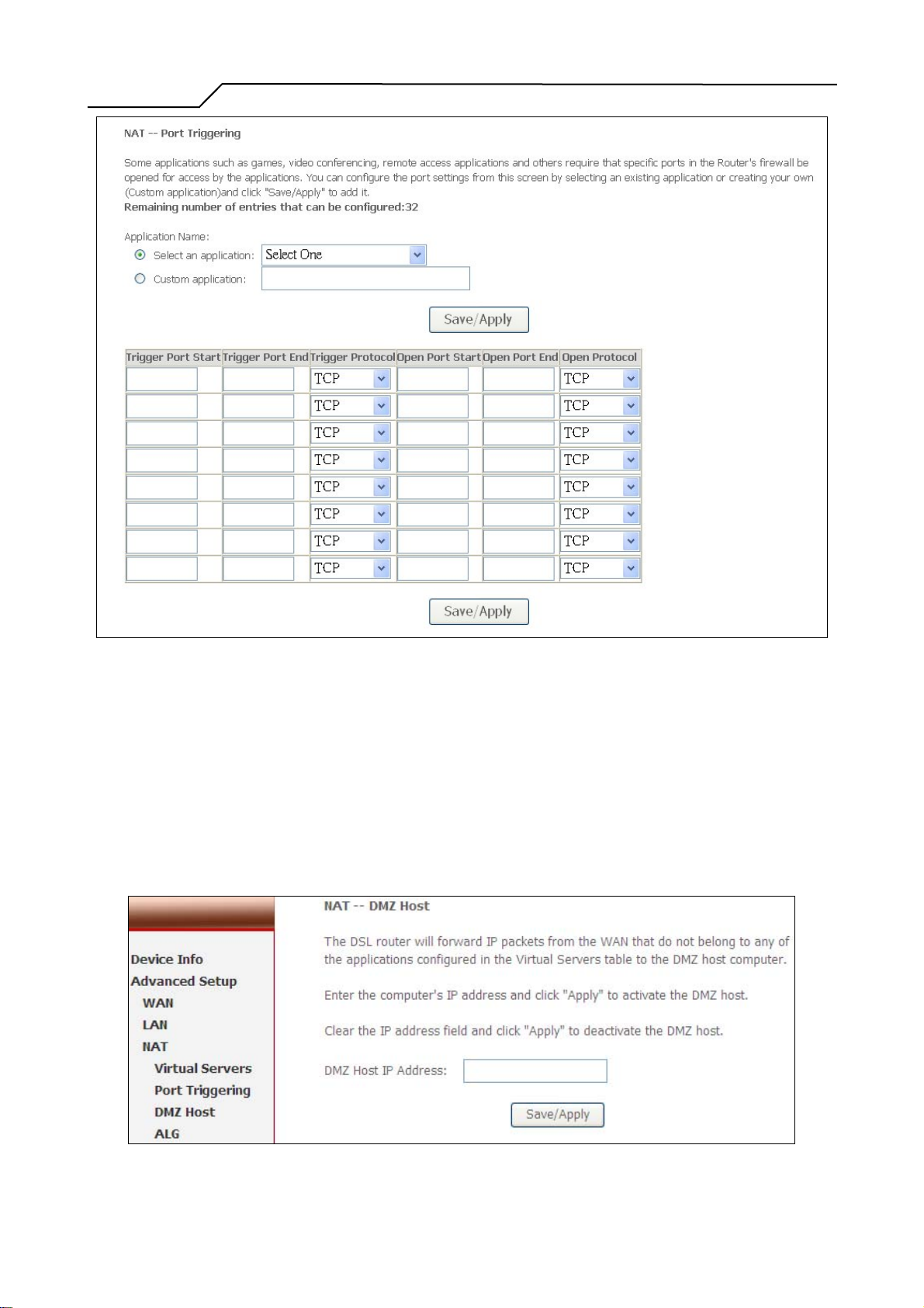
Click on “Add” to enter configuration page to add your own rule(s). Some
applications such as games, video conferencing, remote access applications and
others require that specific ports in the Router's firewall be opened for access by
the applications. You can configure the port settings from this screen by selecting
an existing application or creating your own (Custom application) and click
“Save/Apply” to add it.
To delete the configured rule(s), check the “Remove” box of the specific rule(s)
and click on “Remove”.
- 28 -
Page 29
Manual Ver2.0
5.3.3 DMZ Host
Figure 29. Advanced Setup – NAT – Add Port Triggering
The DSL router will forward IP packets from the WAN that do not belong to any
of the applications configured in the Virtual Servers table to the DMZ host
computer.
Enter the computer's IP address and click “Apply” to activate the DMZ host.
Clear the IP address field and click “Apply” to deactivate the DMZ host.
Figure 30. Advanced Setup – NAT – DMZ Host
- 29 -
Page 30
Manual Ver2.0
5.3.4 ALG
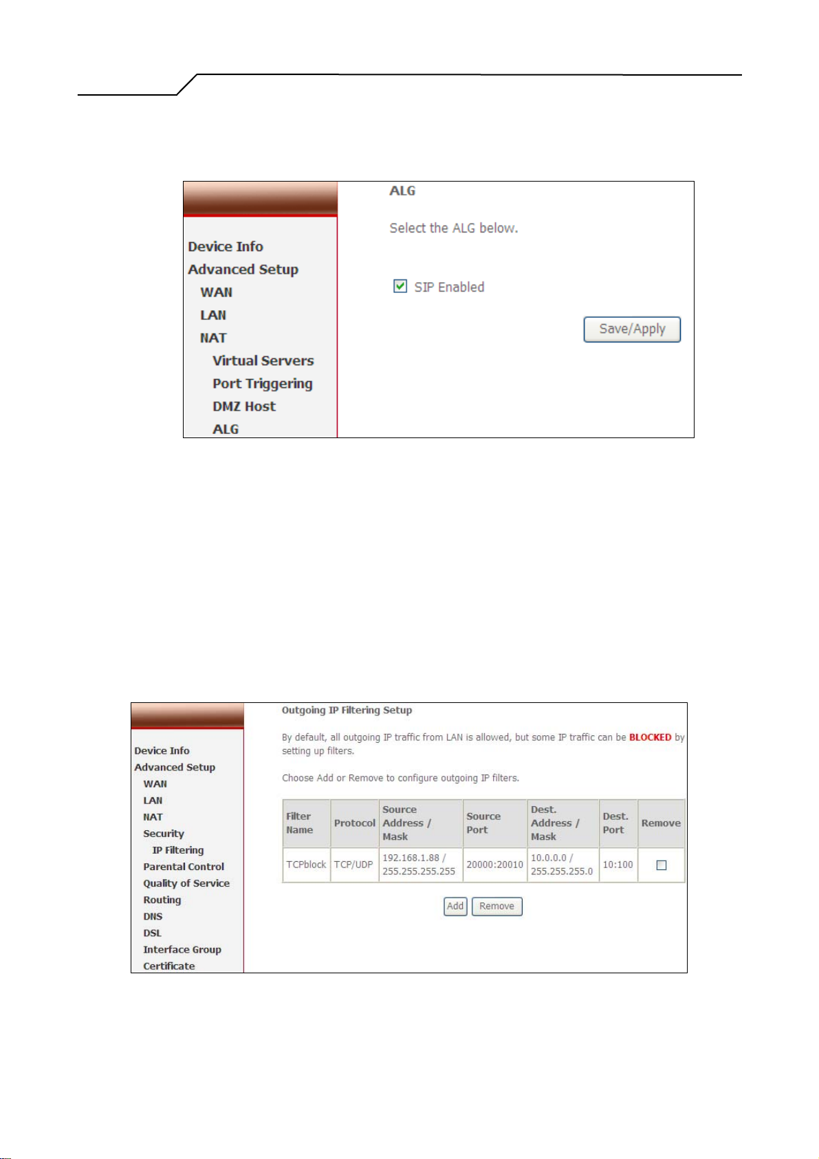
The DSL router will trigger the VoIP related service port when user enable the
ALG function for SIP service.
Figure 31. Advanced Setup – NAT –ALG
5.4 Security
Two functions are supported in Security: Outgoing IP Filtering and MAC Filtering.
5.4.1 IP Filtering
By default, all outgoing IP traffic from LAN is allowed, but some IP traffic can be
BLOCKED by setting up filters. Choose “Add” to configure outgoing IP filters.
To remove, check the item and click “Remove”. Maximum 32 entries can be
configured.
Figure 32. Advanced Setup – Security – Outgoing IP Filtering Setup
- 30 -
Page 31
Manual Ver2.0
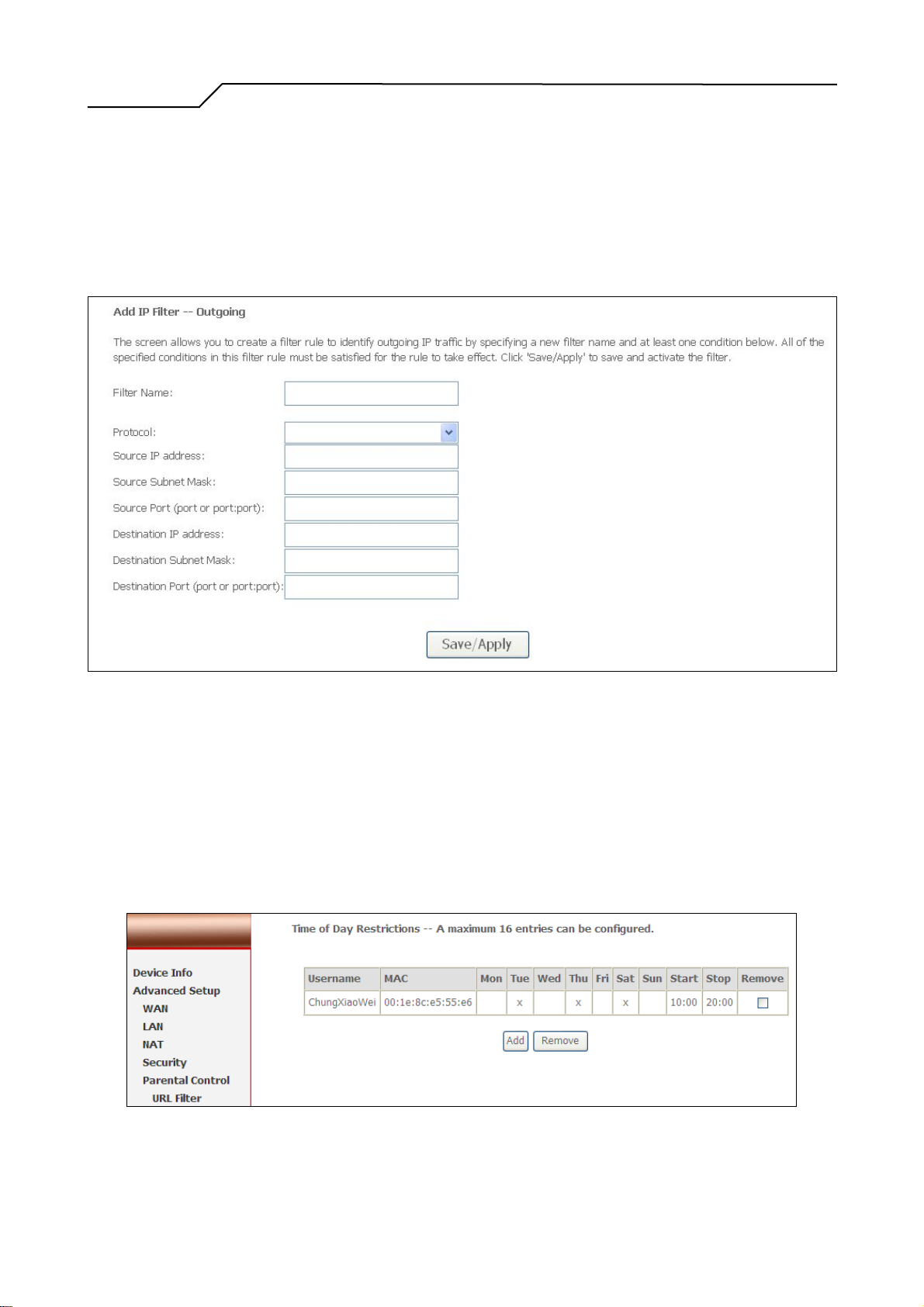
The screen allows you to create a filter rule to identify outgoing IP traffic by
specifying a new filter name and at least one of the conditions below. All of the
specified conditions in this filter rule must be satisfied for the rule to take effect.
Click “Save/Apply” to save and activate the filter. Figure 33 shows the
configuration that prevents a local PC (IP address: 192.168.1.88) from accessing
the specified service (tcp port 10~100) to remote server range 10.0.0.1~254.
Figure 33. Advanced Setup – Firewall – Add new Outgoing IP Filter
5.5 Parental Control
Parental Control allows user to create time of day restriction to a special LAN
device connected to the Router. Click “Add” to configure restriction rules. To
remove, check the item and click “Remove”. Up to 16 entries can be configured
and used.
Figure 34. Advanced Setup – Firewall – Parental Control
- 31 -
Page 32
Manual Ver2.0
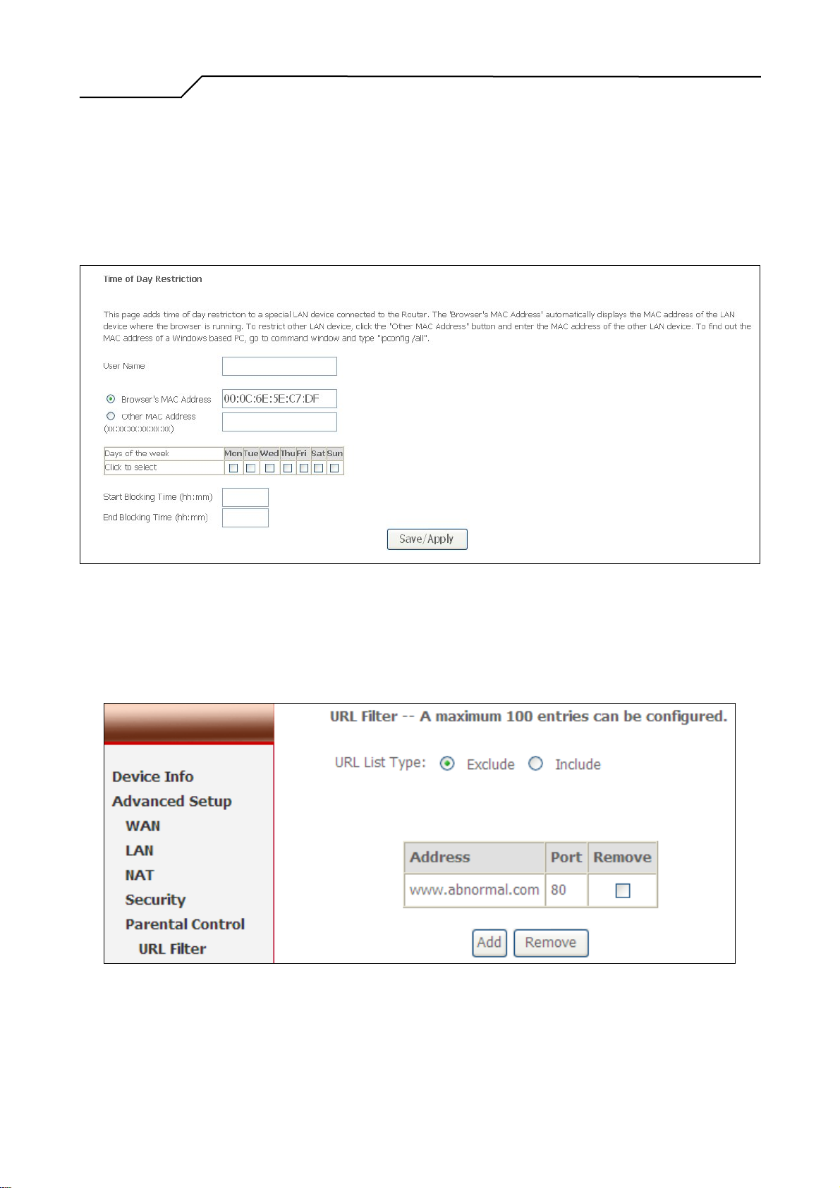
The MAC Address of the “Browser” automatically displays the MAC address of
the LAN device where the browser is running. To restrict other LAN device, click
the “Other MAC Address” button and enter the MAC address of the other LAN
device. To find out the MAC address of a Windows-based PC, go to command
window and type “ipconfig/all”. Click “Save/Apply” to save and activate the
restriction rule.
Figure 35. Advanced Setup – Parental Control – Add new Parental Control
5.5.1 URL Filter
URL filter allows user to block the specified pages for some restriction usage.
Figure 36. Advanced Setup – Parental Control – URL Filter
5.6 Quality of Service
- 32 -
Page 33
Manual Ver2.0
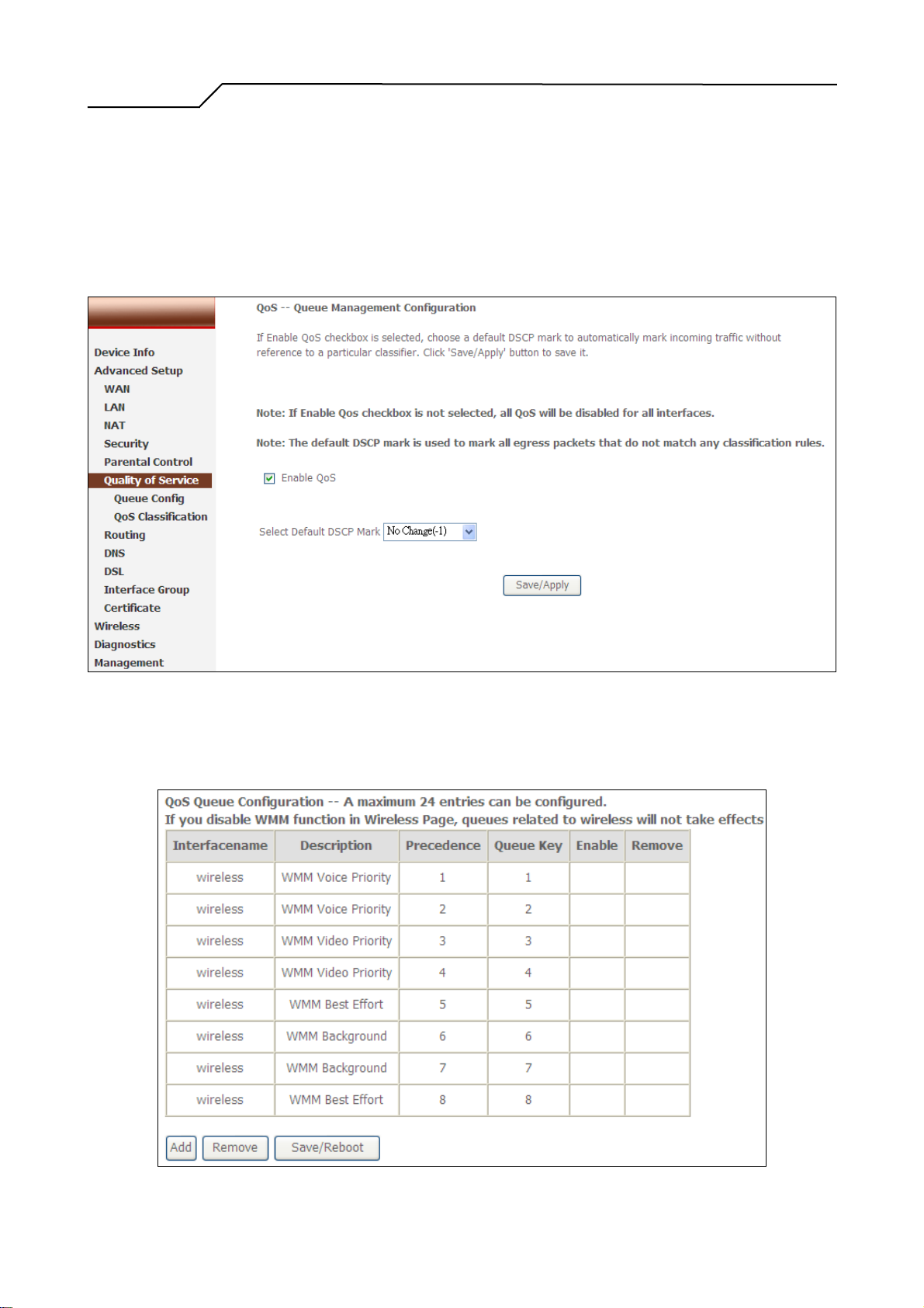
QoS (Quality of Service) is a traffic class rule to classify the upstream traf fic, assign
queuing priority and optionally overwrite the IP header TOS byte. This is to ensure
that the delay-sensitive traffic has higher priority to go to Internet. IP Precedence and
IP TOS (Type of Service) marking, once enabled, will overwrite the correspondent
TOS byte in the IP header. These features, along with Differentiated Service
Configuration, are valid only when your ISP has implemented these services.
5.6.1 Queue Config
Figure 37. Advanced Setup – Quality of Service
- 33 -
Page 34
Manual Ver2.0
Figure 38. Advanced Setup – QoS Queue Configuration
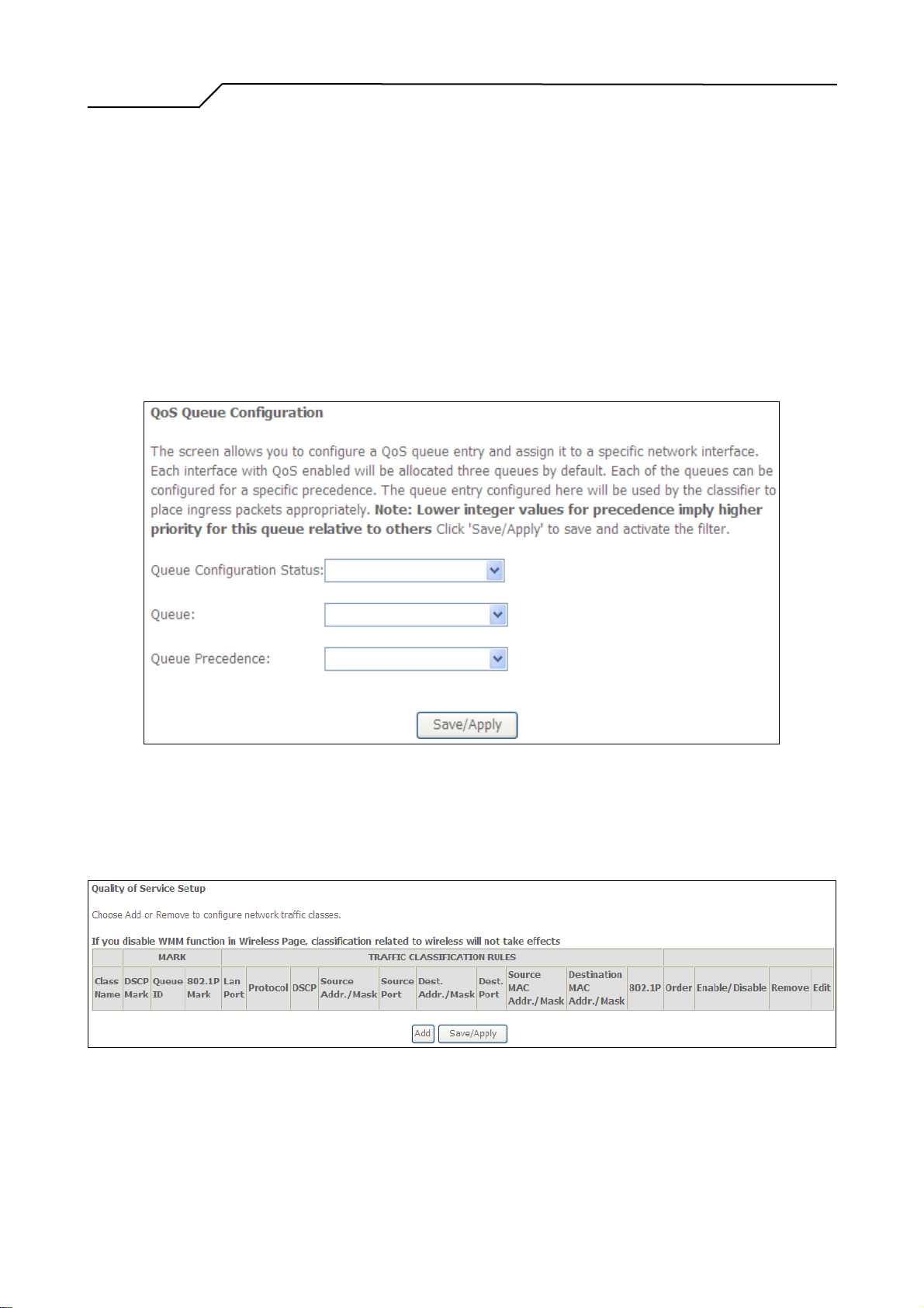
Click on “Add” to configure QoS queue in the figure 28. The screen below – figure 29
allows you to configure a QoS queue entry and assign it to a specific network
interface. Each interface with QoS enabled will be allocated three queues by default.
Each of the queues can be configured for a specific precedence. The queue entry
configured here will be used by the classifier to place ingress packets appropriately.
Note: Lower integer values for precedence imply higher priority for this queue
relative to others Click 'Save/Apply' to save and activate the filter.
Figure 39. Advanced Setup – QoS Queue Configuration
5.6.2 Quality of Service Setup
Figure 40. Advanced Setup – QoS Setup
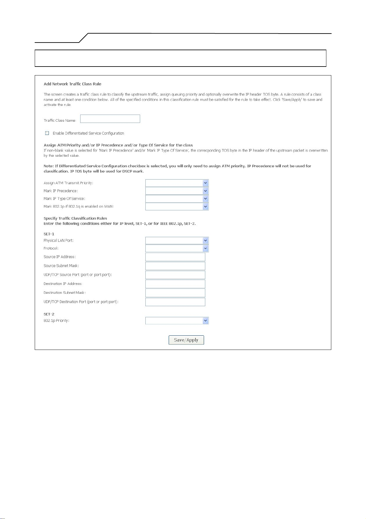
Click on “Add” to create a class to identify the IP traffic by specifying at least one
condition below. If multiple conditions are specified, all of them take effect.
- 34 -
Page 35
Manual Ver2.0
Note: SET-1 and SET-2 conditions cannot be configured together to form a QoS rule.
Figure 41. Advanced Setup – Add new QoS rule
5.7 Routing
There are three routing information related settings.
5.7.1 Routing – Default Gateway
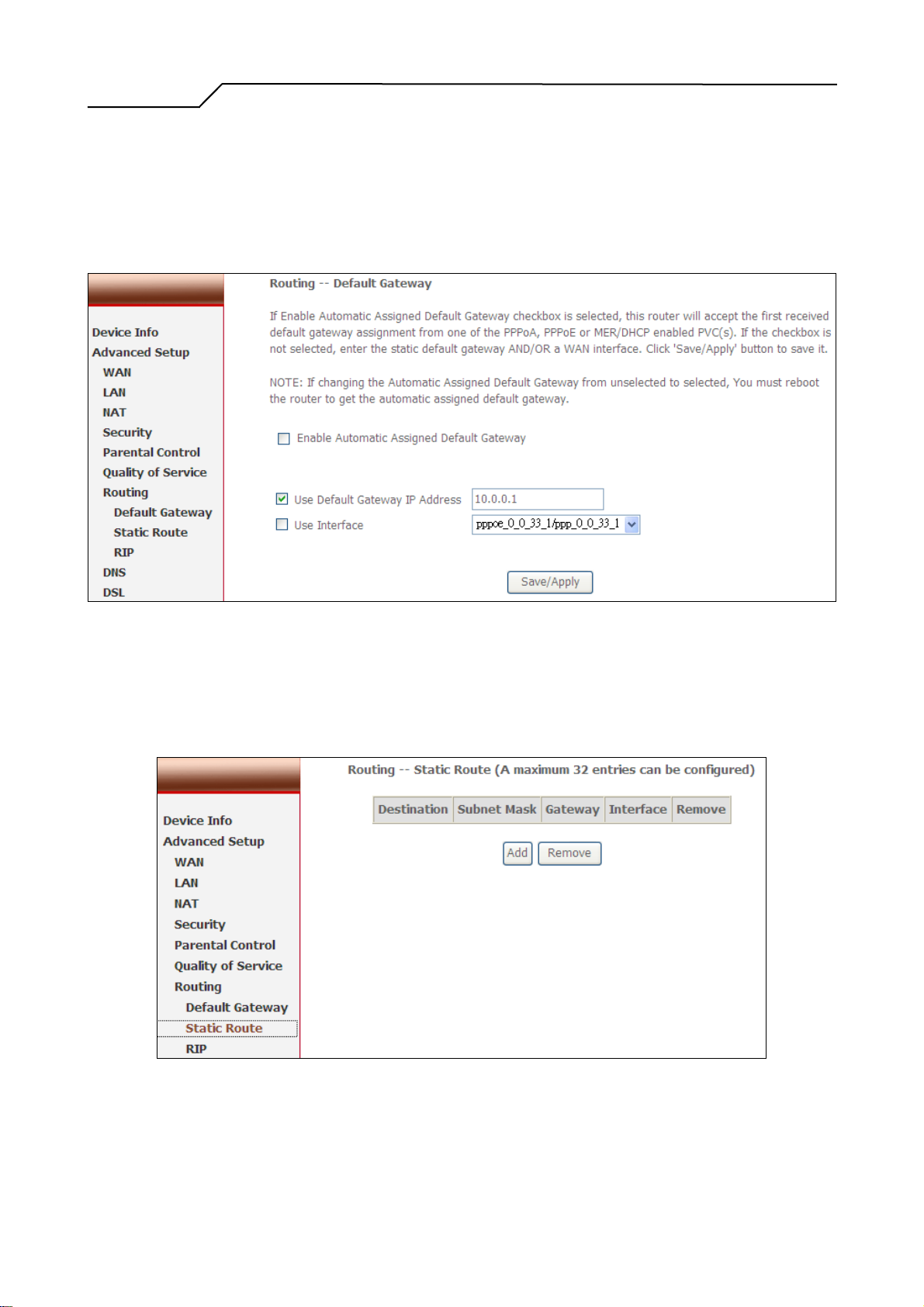
If “Enable Automatic Assigned Default Gateway” checkbox is selected,
NWAR3600 will accept the first received default gateway assignment from one of
the PPPoA, PPPoE or MER/DHCP enabled PVC(s). If the checkbox is not
- 35 -
Page 36
Manual Ver2.0
selected, enter the static default gateway AND/OR a WAN interface. Click
“Apply” button to save it.
NOTE: If changing the “Enable Automatic Assigned Default Gateway” from
unselected to selected, you must reboot NWAR3600 to activate the automatic
assigned default gateway.
Figure 42. Advanced Setup – Routing – Default Gateway
5.7.2 Routing – Static Route
Click on “Add” to create a new Static Route. Up to 32 entries can be configured.
Figure 43. Advanced Setup – Routing – Static Route
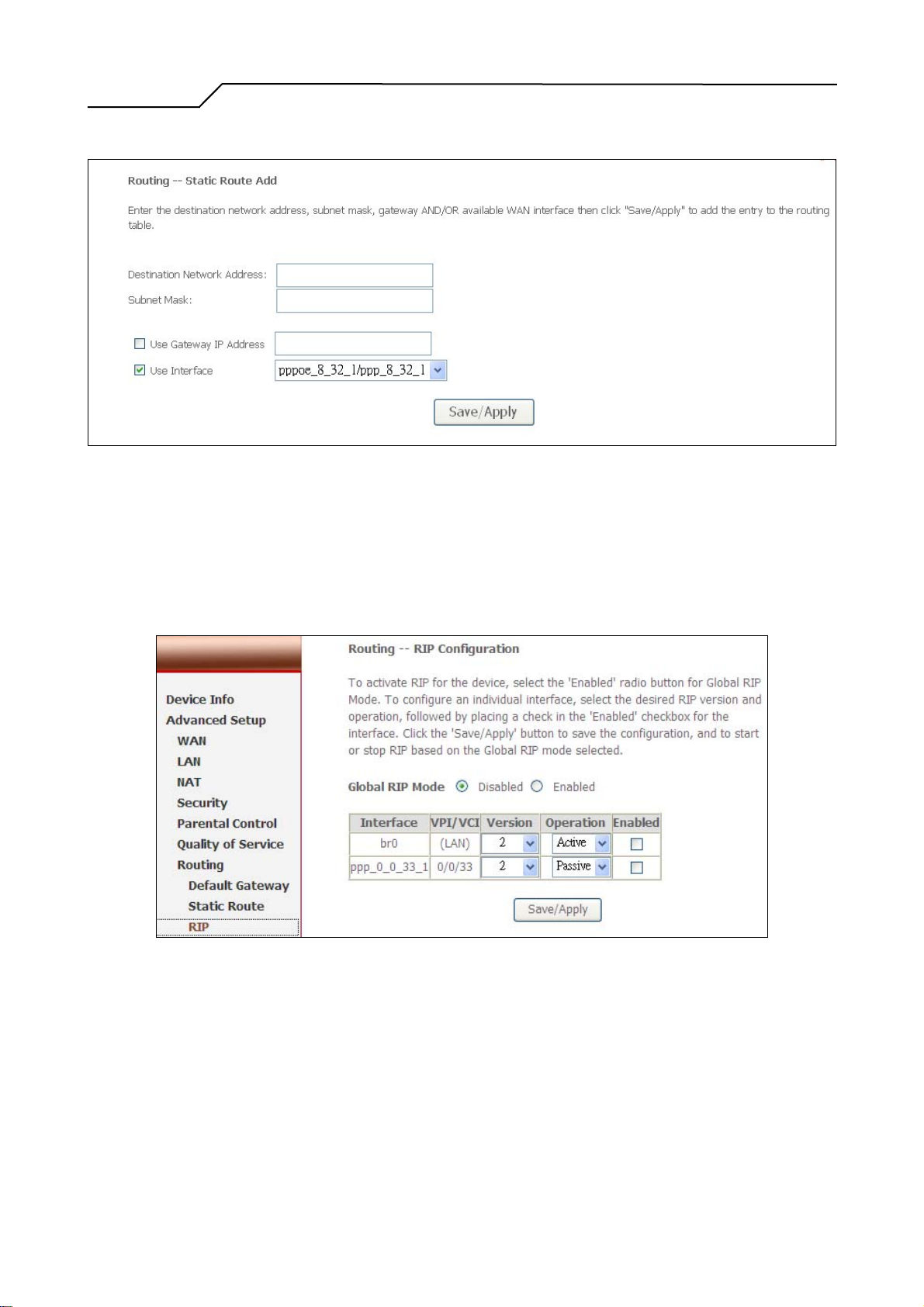
Enter the destination network address, subnet mask, gateway AND/OR
available WAN interface, then click “Apply” to add the entry to the routing
- 36 -
Page 37
Manual Ver2.0
table.
Figure 44. Advanced Setup – Routing – Add new Static Route
5.7.3 Routing – RIP
The Routing Information Protocol (RIP) is designed for exchanging routing
information within a small to medium-size Internet work.
Figure 45. Advanced Setup – Routing – RIP
To configure an individual interface, select the desired RIP version and
operation:
RIP Version 1: Class-based IP network.
RIP Version 2: Classless IP network.
Operation Active: Broadcast and listen to other RIP enabled devices.
- 37 -
Page 38
Manual Ver2.0
5.8 DNS
5.8.1 DNS Server
Operation Passive: Listen only.
Placing a check in the “Enabled” checkbox for the interface to complete the
configuration. Click the “Apply” button to save the configuration. To start/stop
RIP for NWAR3600, select the “Enabled/Disabled” radio button for Global RIP
Mode.
.
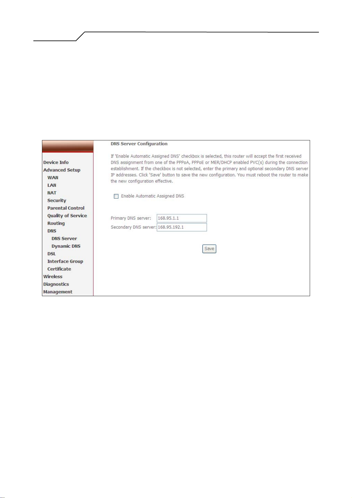
Figure 46. Advanced Setup – DNS Server
If “Enable Automatic Assigned DNS” checkbox is selected, NWAR3600 will
accept the first received DNS assignment from one of the PPPoA, PPPoE or
MER/DHCP enabled PVC(s) during the connection establishment. If the checkbox
is not selected, enter the primary and optional secondary DNS server IP addresses.
Click “Apply” button to save it.
NOTE: If changing from unselected “Enable Automatic Assigned DNS” to
selected, you must reboot NWAR3600 to get the automatic assigned DNS
addresses.
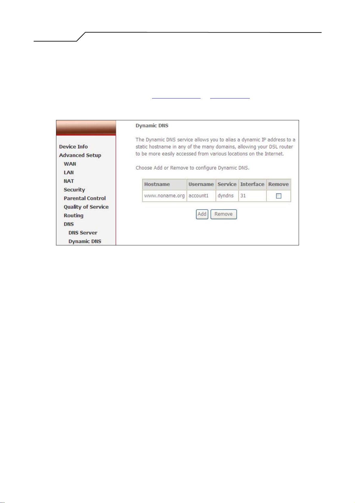
5.8.2 Dynamic DNS
The Dynamic DNS service allows you to alias a dynamic IP address to a static
- 38 -
Page 39
Manual Ver2.0
hostname in any of the domains. This function allows your NWAR3600 to be
more easily accessible from various locations of the Internet.
Choose “Add” to configure Dynamic DNS.
Before you proceed, please visit one of these two website to apply your own
Dynamic DNS service: www.dyndns.org or www.tzo.com.
To remove, check the item and click “Remove”
Figure 47. Advanced Setup – DNS – Dynamic DNS
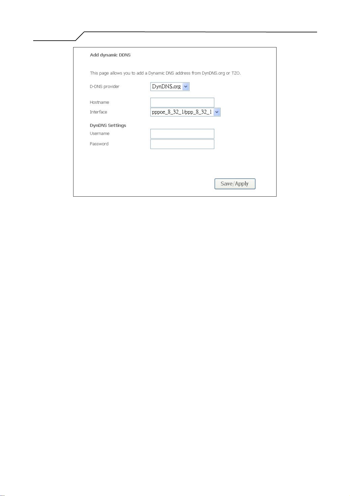
Select your Dynamic DNS service provider from ‘D-DNS provider’, and enter
your registration information. Click “Save/Apply” to save the configuration.
- 39 -
Page 40
Manual Ver2.0
5.9 DSL
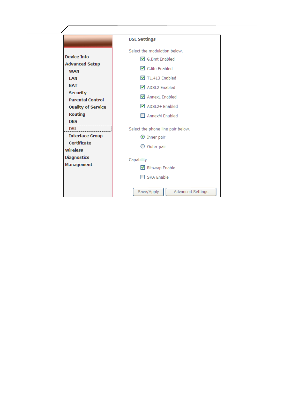
This page allows you configure DSL related settings including Modulations, Phone
Line Pair, and Capability. Due to the characteristics of DSL, any change to default
settings is not recommended. Please consult your service provider for advice only if
configuration is mandatory.
Figure 48. Advanced Setup – DNS – Add Dynamic DNS
- 40 -
Page 41
Manual Ver2.0
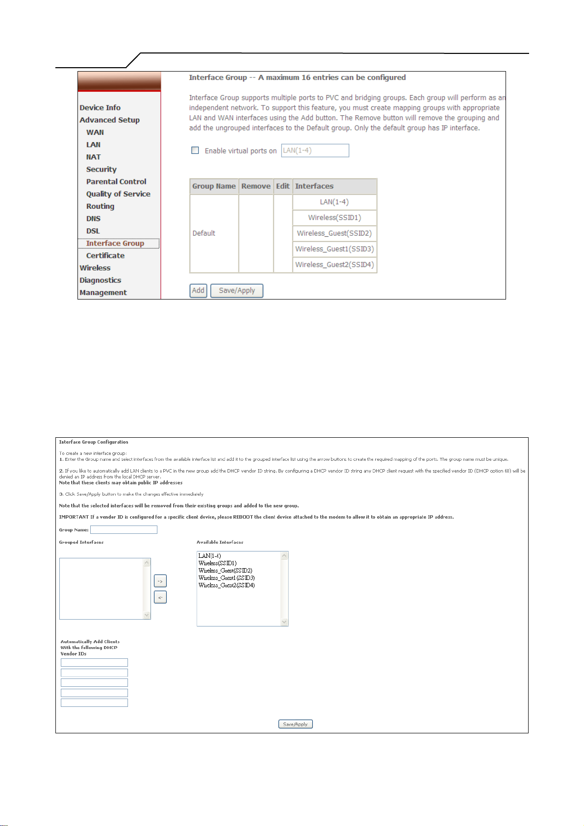
5.10 Interface Group
Interface Group supports multiple ports to PVC and bridging groups. Each group will
perform as an independent network. To support this feature, you must create mapping
groups with appropriate LAN and WAN interfaces. By default, all interfaces are
included in the Default group. And only the Default group has IP interface to access
Router‘s configuration window. The interfaces which have been selected to form a
mapping group will no longer have the ability to access the router configuration
window.
First, check the “Enable Virtual Ports on” box to enable Interface Group.
Figure 49. Advanced Setup – DSL
- 41 -
Page 42
Manual Ver2.0
Figure 50. Advanced Setup – Interface Group
Click the “Add” button to enter Interface Group configuration window.
Enter the group name and select the specific interfaces from “Available Interfaces”
(Default group) to “Grouped Interfaces” and then click “Save & Apply” to apply
your settings.
Figure 51. Advanced Setup – Add Interface Group
- 42 -
Page 43
Manual Ver2.0
5.11 Certificate
Click on Certificate in the Advanced Setup menu to open the Certificate menu, which
includes:
• Local
• Trusted CA
5.11.1 Local
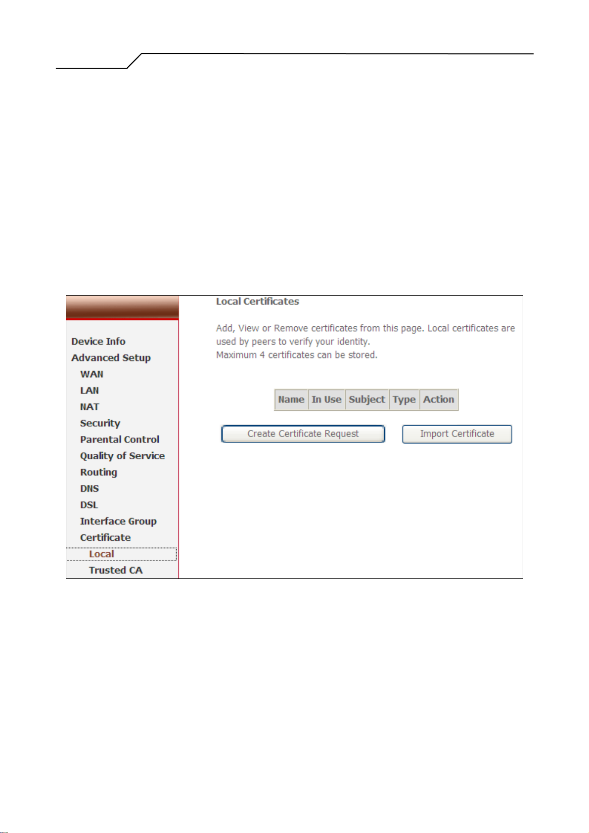
After creating the certificates, you can Add, View or Remove certificates from this
page. Local certificates are used by peers to verify your identity. Maximum 4
certificates can be stored. See Figure 52
Figure 52. Advanced Setup – Certificate - Local
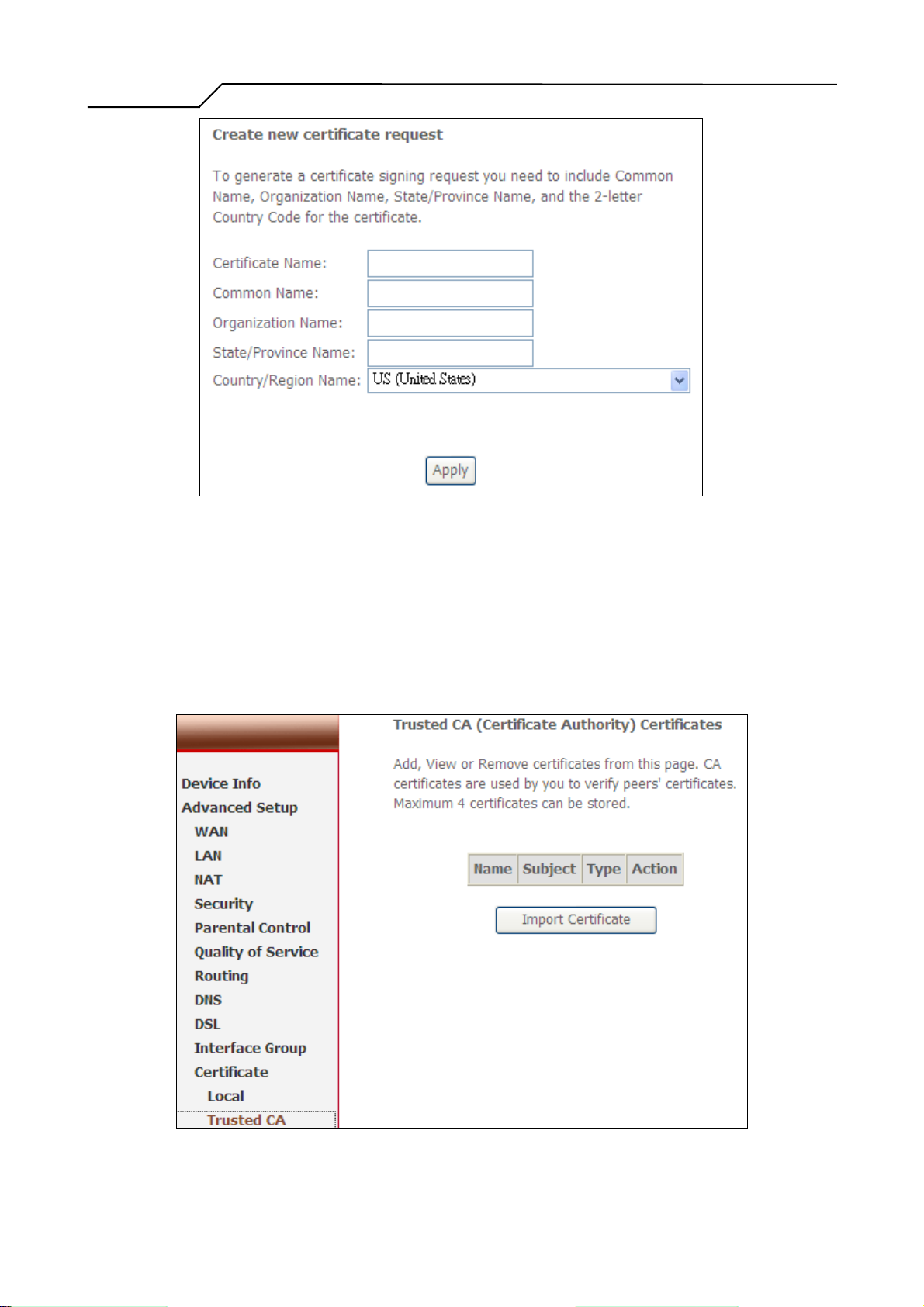
To generate a certificate signing request you need to include Common Name,
Organization Name, State/Province Name, and the 2-letter Country Code for the
certificate. See Figure 53.
- 43 -
Page 44
Manual Ver2.0
Figure 53. Advanced Setup – Certificate - Local
5.11.2 Trusted CA
To import the Certificate of Trusted CA, see Figure 54, you can click the button of
Import Certificate.
Figure 54. Advanced Setup – Certificate – Trusted CA
- 44 -
Page 45
Manual Ver2.0
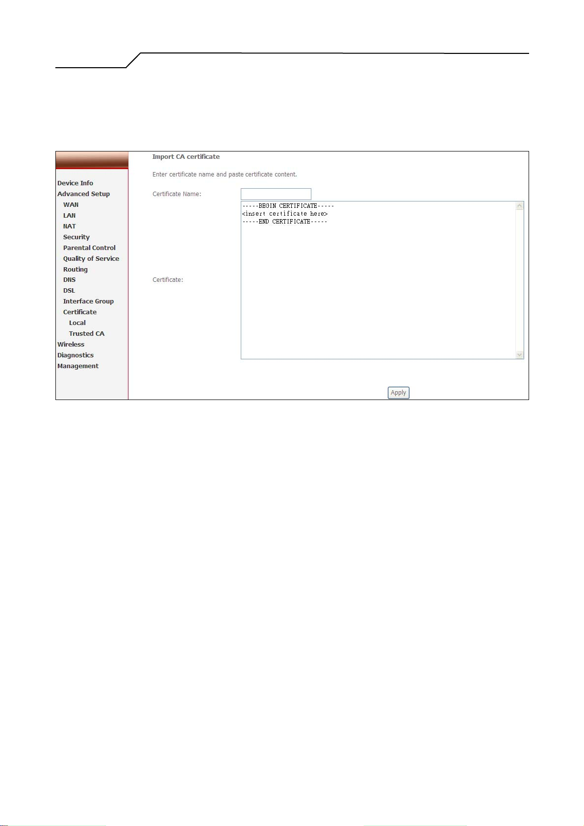
To import the CA certificate with the name and the required CA strings. See Figure
55.
Figure 55. Advanced Setup – Certificate – Import CA certificate
- 45 -
Page 46
Manual Ver2.0
6. Wireless Setup
6.1 Basic
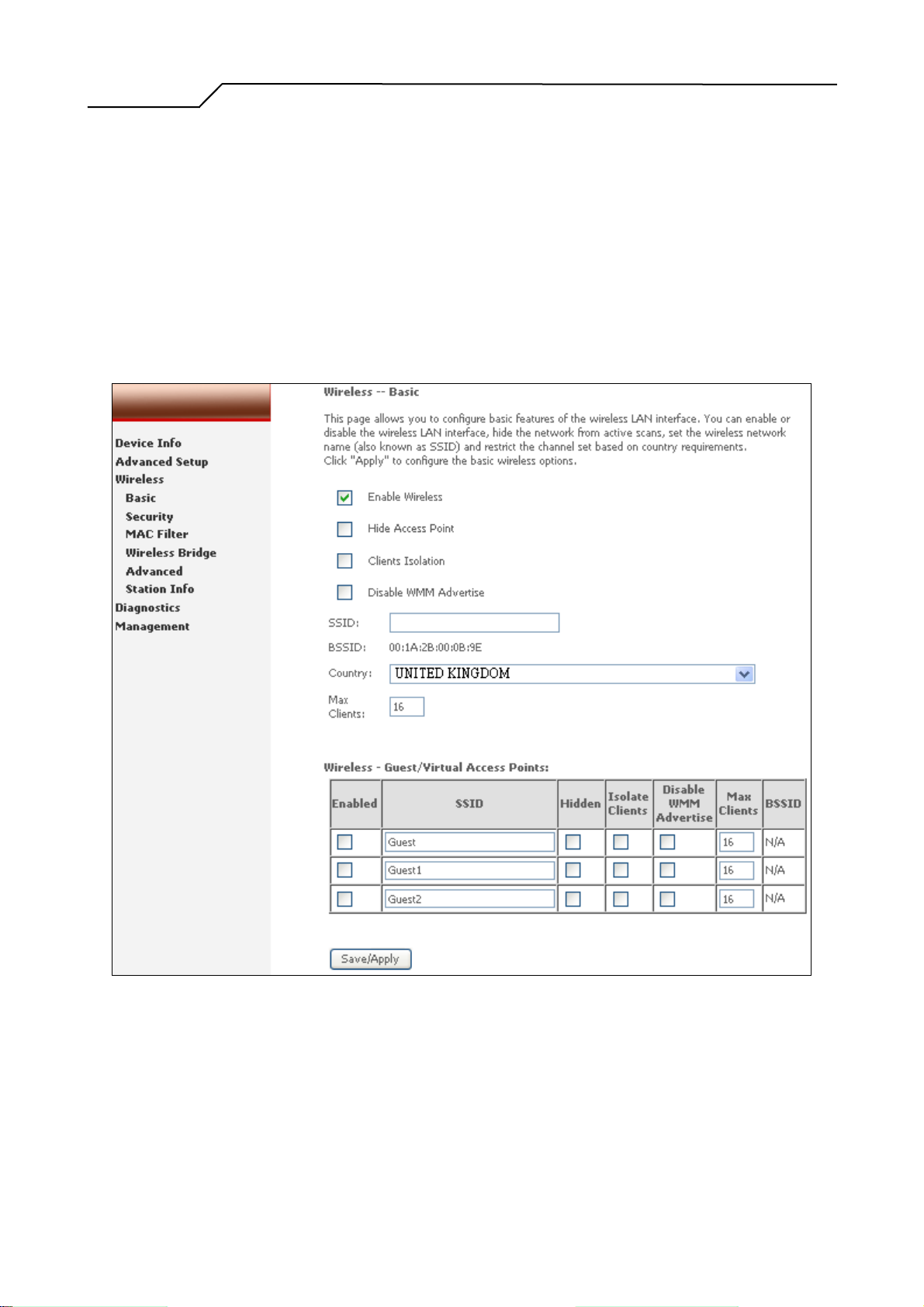
This page allows you to configure basic features of the wireless LAN interface. You
can enable or disable the wireless LAN interface, hide the network from active scans
(no broadcasting of your network name), set the wireless network name (also known
as SSID), and restrict the channels based on nation’s requirements.
Click “Save/Apply” to save the configurations.
Figure 56. Wireless Setup – Basic
6.2 Security
Four types of wireless security are provided: Shared (WEP), 802.1x, WPA/WPA2, and
WPA/WPA2-PSK.
6.2.1 WEP
- 46 -
Page 47
Manual Ver2.0
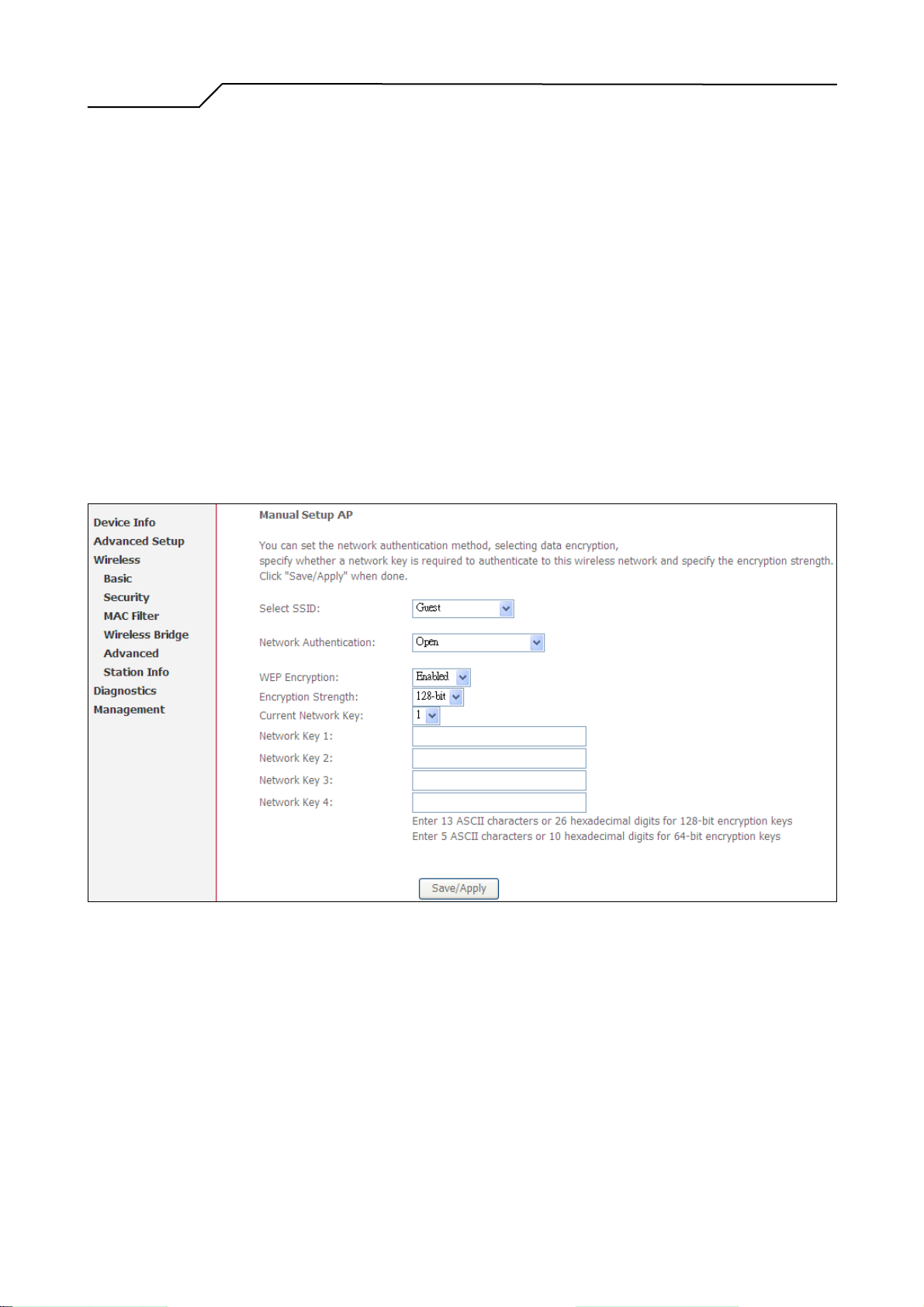
WEP (Wired Equivalent Privacy) provides security by encrypting data over radio
waves when data is transmitted from one end point to another. WEP is the weakest
security method but the easiest one to configure. To enable WEP, select the
following items step by step:
Network Authentication: Shared
Data Encryption: Enabled
Encryption Strength: 128-bit (recommended for better security) or 64-bit
Four keys for both encryption strengths can be stored here. Enter 13 ASCII
characters or 26 hexadecimal digits for 128-bit encryption keys. Enter 5 ASCII
characters or 10 hexadecimal digits for 64-bit encryption keys. Select which key
(1 ~ 4) to use from “Current Network Key”. Click “Save/Apply” to save the
configuration.
Figure 57. Wireless Setup – Security – WEP
6.2.2 802.1X
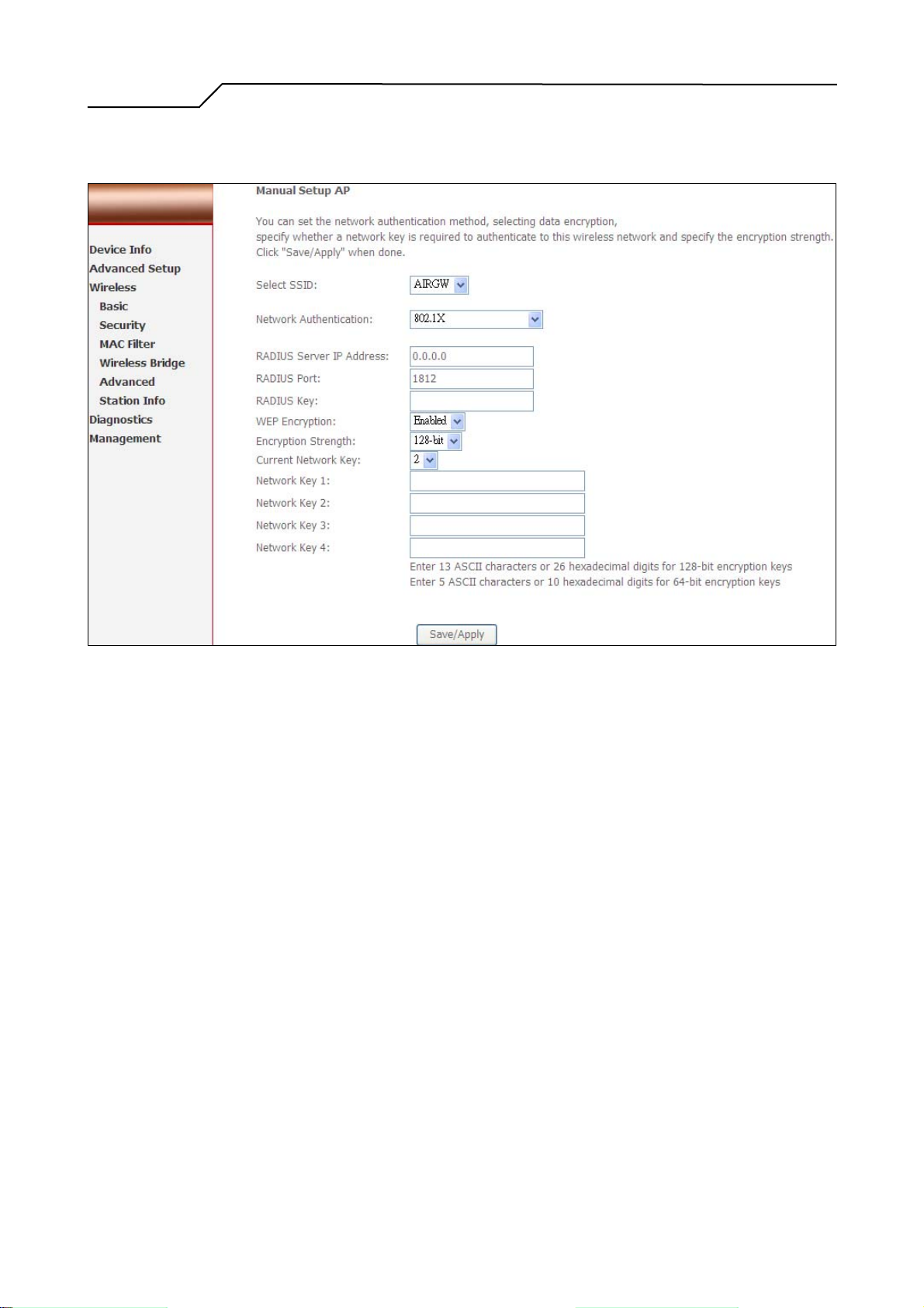
802.1X addresses the WEP weakness by adding user authentication, via RADIUS
server. So you need to have your RADIUS server up and running before using
802.1X. To enable 802.1X, select “802.1X” in “Network Authentication”. Enter
your RADIUS server IP address, port number (default: 1812), and key. Follow
- 47 -
Page 48
Manual Ver2.0
section 6.2.1 to configure your WEP key and select “Save/Apply” to save your
configuration.
6.2.3 WPA/WPA2
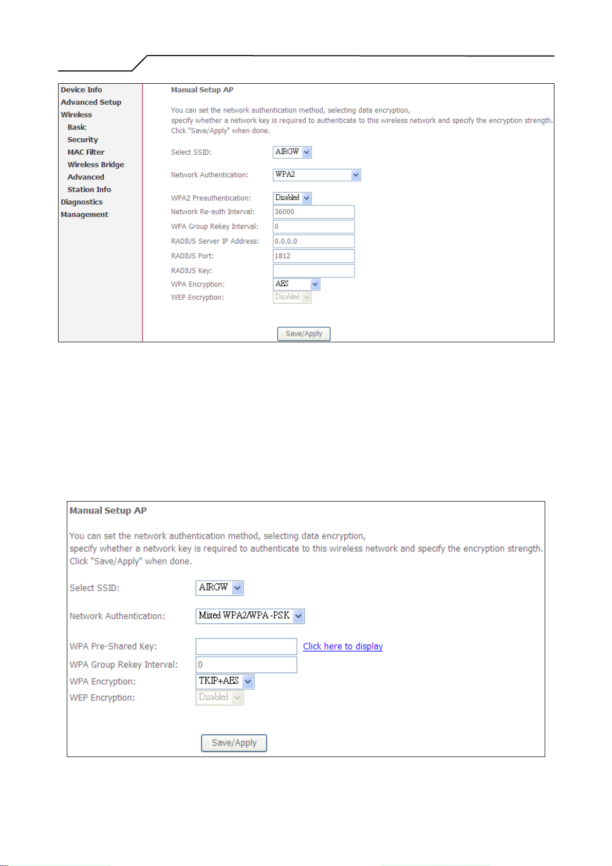
WPA/ WPA2 (Wi-Fi Protected Access) is the strongest wireless security provided
by NWAR3600. Like 802.1X, WPA must co-work with RADIUS server as well.
To enable WPA/WPA2, select the following items step by step:
Network Authentication: WPA/WP A2
WPA2 Preauthentication: Default: Disabled (WPA2 only)
Network Re-auth Interval: in seconds. Default: 36000 (WPA2 only)
WPA Group Rekey Interval: in seconds. Default: 0 (no re-keying).
RADIUS Server IP Address/Port/Key: must match your RADIUS server.
WPA Encryption: TKIP (select AES or TKIP+AES for WPA2).
Check your supplicant capability before you decide which one to use.
Figure 58. Wireless Setup – Security – 802.1X
- 48 -
Page 49
Manual Ver2.0
6.2.4 WPA/WPA2-PSK
WPA-PSK lets you take advantage of WPA without the hassle of setting up your
own RADIUS server. To enable WPA-PSK, select “WPA-PSK” in “Network
Authentication”. Enter 8 to 63 ASCII codes or 64 hexadecimal (0~9, A~F) digits
in “WPA Pre-Shared Key”. Click “Save/Apply” to save the configuration.
Figure 59. Wireless Setup – Security – WPA
Figure 60. Wireless Setup – Security – WPA-PSK
- 49 -
Page 50
Manual Ver2.0
6.3 MAC Filter
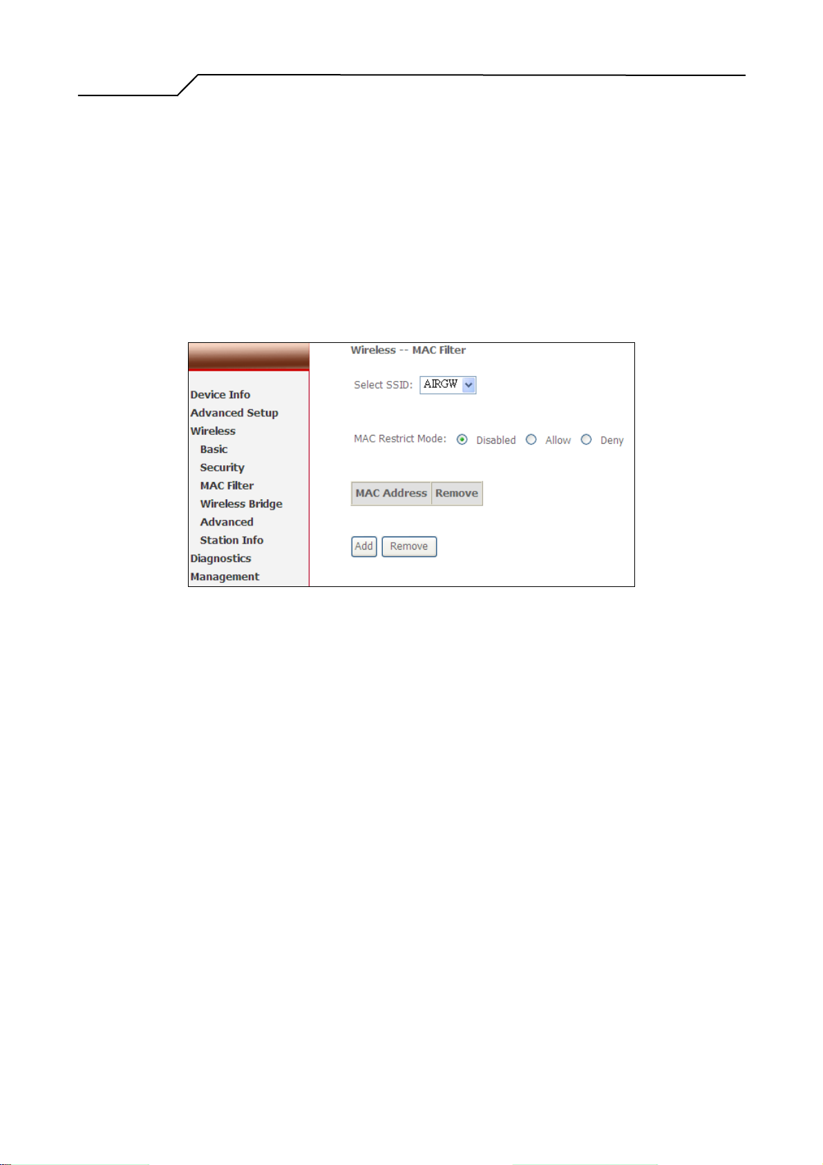
Wireless MAC filter allows you to implement access control based on device’s MAC
address.
When you select “Allow” in “MAC Restrict Mode”, only data from devices with
matching MAC addresses in filter table can access NWAR3600. If you select “Deny”
in “MAC Restrict Mode”, every device can access NWAR3600 except those that have
matching MAC addresses in the filter table. To add filter entry, click on “Add” and
enter the MAC address of NWAR3600. Click “Save/Apply” to save the configuration.
To “delete” the entry, select the entry and click “Remove”.
Figure 61. Wireless Setup – MAC Filter
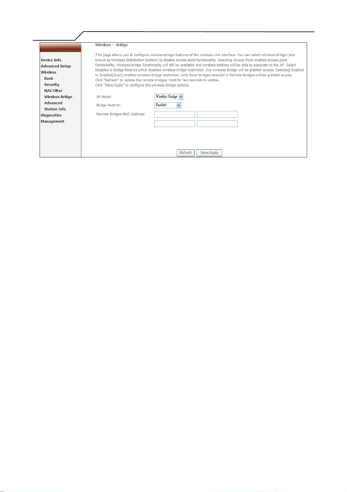
6.4 Wireless Bridge
Wireless Bridge (also known as Wireless Distribution System) can bridge data
between two APs, which is particularly useful while wired cabling is not available.
Note: only APs running in the same channel can be bridged.
AP Mode: Wireless Bridge- listens and answers other APs only
Access Point- Wireless Bridge also with AP functionality
Bridge Restrict: Disabled- any AP will be granted access
Enabled- only assigned APs (Max. 4) with specified MAC address
Enabled (Scan) - as above, but NWAR3600 will scan available AP
will be granted access
for you to select.
Refresh: re-scan the available AP
Save/Apply: save the configuration
- 50 -
Page 51
Manual Ver2.0
6.5 Advanced
Figure 62. Wireless Setup – Wireless Bridge
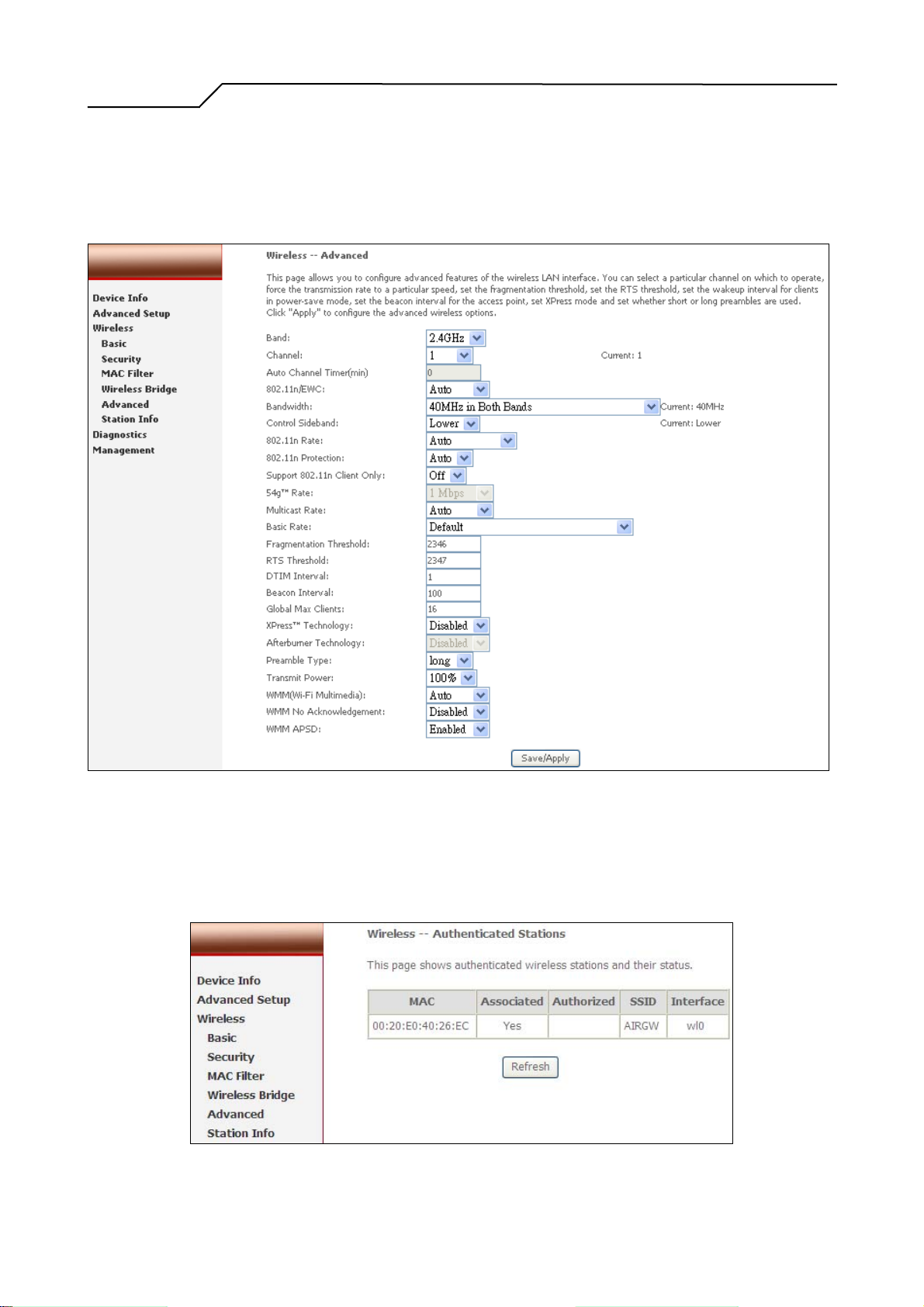
In most cases, NWAR3600 work well with wireless default settings. Modification is
not recommended unless you are very familiar with these parameters.
AP Isolation: Separate local PCs from other PCs which have associated to other APs
in the same network. Default: Disabled.
Channel: Select the appropriate channel from the provided list to correspond with
your network settings. All devices in your wireless network must use the
same channel in order to function correctly. Or select “Auto” to allow AP to
decide its operating channel based on current environment. Default: 11.
Auto Channel Timer (min): Expiration time for AP to adjust operating channel.
54g Rate: The range is from 1 to 54Mbps. The data transmission rate should be set
according to the speed of your wireless network. You can set one
transmission speed, or keep the default setting “Auto” to have the router
automatically detect the fastest possible data rate.
Multicast Rate: The range is from 1 to 54Mbps. The data transmission rate of the
multicast packets should be set according to the speed of your
wireless network. You can set one transmission speed, or keep the
default setting “Auto” to have the router automatically detect the
fastest possible data rate.
Basic Rate: Select the basic rate that wireless clients must support.
Fragmentation: This value should remain at its default setting of 2346. The range is
256-2346 bytes. This value specifies the maximum packet size
- 51 -
Page 52

Manual Ver2.0
before data is fragmented into multiple packets. If you experience a
high packet error rate, you may slightly lower the Fragmentation
value. Setting the Fragmentation too low may result in poor network
performance. Only slight adjustment of this value is recommended.
RTS Threshold: This value should remain at its default setting of 2347. The range is
0-2347 bytes. Should you encounter inconsistent data flow, only
slight adjustment of this value is recommended. If a network packet
is smaller than the preset RTS threshold size, the RTS/CTS
mechanism will not be enabled. NWAR3600 sends Request to Send
(RTS) frames to a particular receiving station and negotiates the
transmission of a data frame. After receiving an RTS, the wireless
station responds with a Clear to Send (CTS) frame to acknowledge
the right to begin transmission.
DTIM Interval: This value, between 1 and 255 milliseconds, indicates the interval of
the Delivery Traffic Indication Message (DTIM). A DTIM interval is
a countdown field which is used to inform clients about the next
window for listening to broadcast and multicast messages. When
NWAR3600 has buffered broadcast or multicast for associated
clients, it sends the next DTIM with a DTIM Interval value. Its
clients hear the beacons and awaken to receive the broadcast and
multicast message. Default: 1.
Beacon Interval: Enter a value between 1 and 65535 milliseconds. The Beacon
Interval indicates the frequency interval of the beacon. A beacon is
a packet broadcast by NWAR3600 to synchronize the wireless
network. Default: 100.
XPress Technology: Proprietary feature to increase wireless data rate. Must co-work
with client device which supports the same feature. Default:
Disabled.
54g Mode: There are 4 selections. Select 54g Auto for the widest compatibility. Select
54g Performance for the fastest performance. Select 54g LRS if you are
experiencing difficulty with legacy 802.11b equipment. Select 802.11b
only to operate at 802.11b only environment.
54g protection: In Auto mode, NWAR3600 will use RTS/CTS to improve 802.11g
performance in mixed 802.11g/802.11b network. Turn off protection
to maximize 802.11g throughput under most conditions.
Preamble Type: The preamble is used to synchronize the transmitter and receiver and
- 52 -
Page 53
Manual Ver2.0
derives common timing relationship. The Short preamble improves
throughput but not all wireless clients support short preamble type.
Transmit Power: 5-level of transmit power are available: 20%, 40%, 60%, 80%,
and 100%. Default: 100%.
6.6 Station Info
This page shows authenticated wireless stations and their status.
Figure 63. Wireless Setup – Advanced
Figure 64. Wireless Setup – Station Info
- 53 -
Page 54
Manual Ver2.0
7. Diagnostics
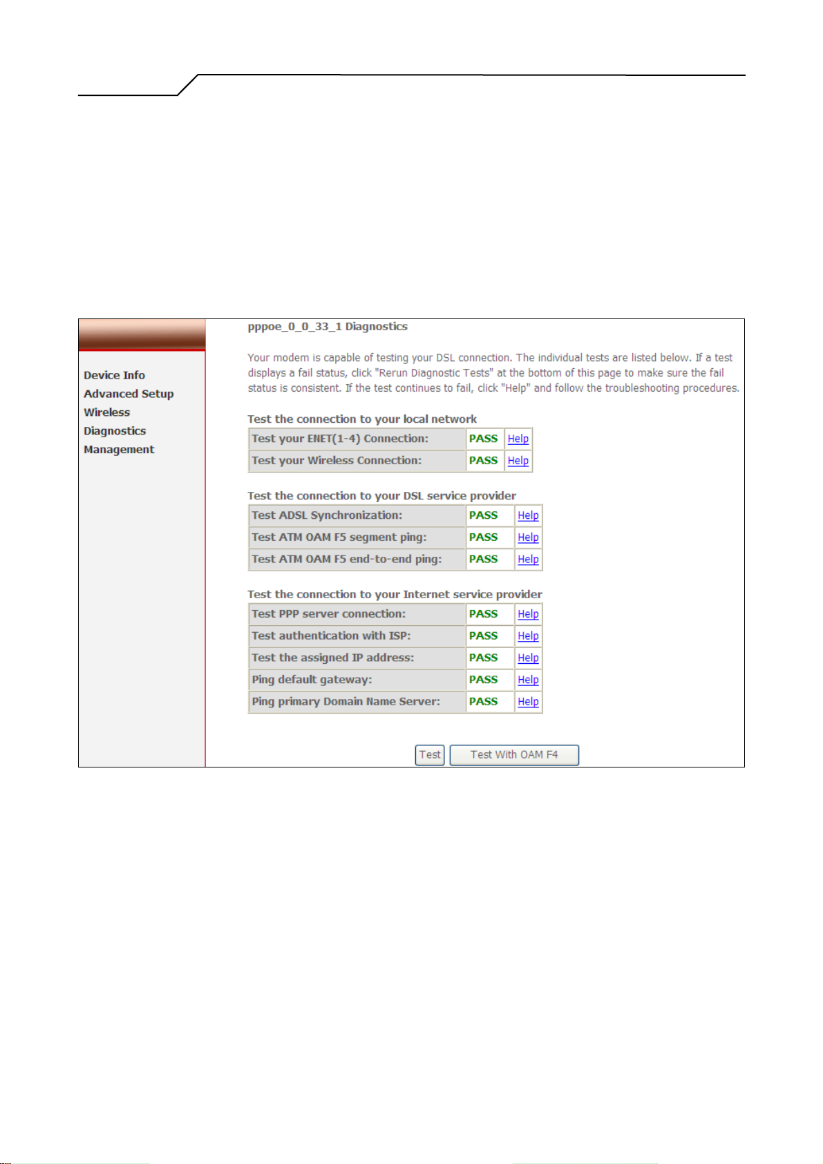
This page allows users to test the Ethernet port connection, DSL port connection, and
connection to the Internet Service Provider. If a test displays a fail status, click “Test”
at the bottom of the page to re-run the diagnostic test to make sure the fail status is
consistent. If the test continues to show fail, click “Help” on the failed item for the
troubleshooting procedures.
Figure 65. Diagnostics
- 54 -
Page 55
Manual Ver2.0
8. Management
8.1 Settings
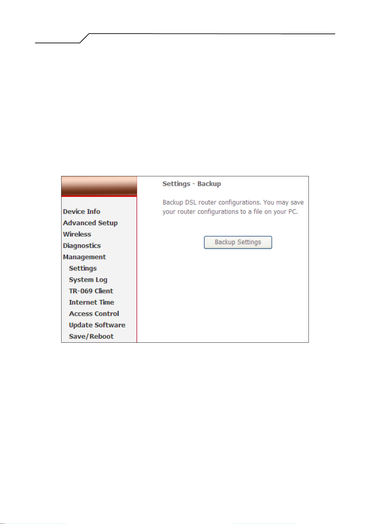
System Administrator can do the NWAR3600 settings backup, update, and restore
default here. The settings can be saved from NWAR3600 to PC. The saved setting file
can also be loaded from PC to NWAR3600. These 2 functions can help the system
administrator to manage large amount of NWAR3600 efficiently. Restore Default
would set the NWAR3600 with the factory default configuration.
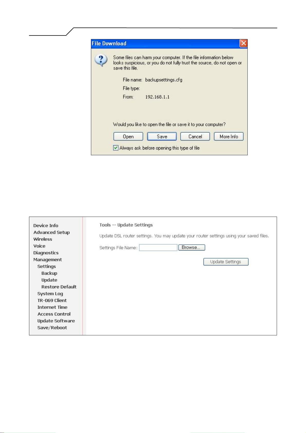
To backup the current configurations, click on “Backup Settings”, and a File
Download window will pop up.
Figure 66. Management – Settings – Backup Settings
Click on “Save” and select the destination of the backup file (backupsettings.cfg) in
your local PC. Click on “Save” again to save your backup file.
- 55 -
Page 56
Manual Ver2.0
Figure 67. Management – Settings – File Download
To update the configuration, click on “Browse” and a Choose-File-window will pop
up. Locate the saved file and click on “Update Settings”. NWAR3600 will modify its
settings based on the update file.
Figure 68. Management – Settings – Update
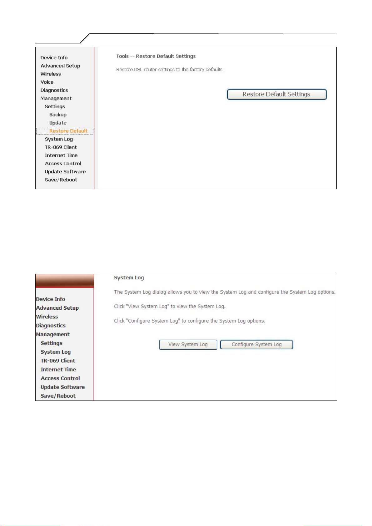
To restore the router to its factory default settings, click on “Restore Default Settings”.
- 56 -
Page 57
Manual Ver2.0
Figure 69. Management – Settings – Restore Default
8.2 System Log
This allows System Administrator to view the System Log and configure the System
Log options. Click on “View System Log” to see the router log based on your
configuration.
Figure 70. Management – System Log
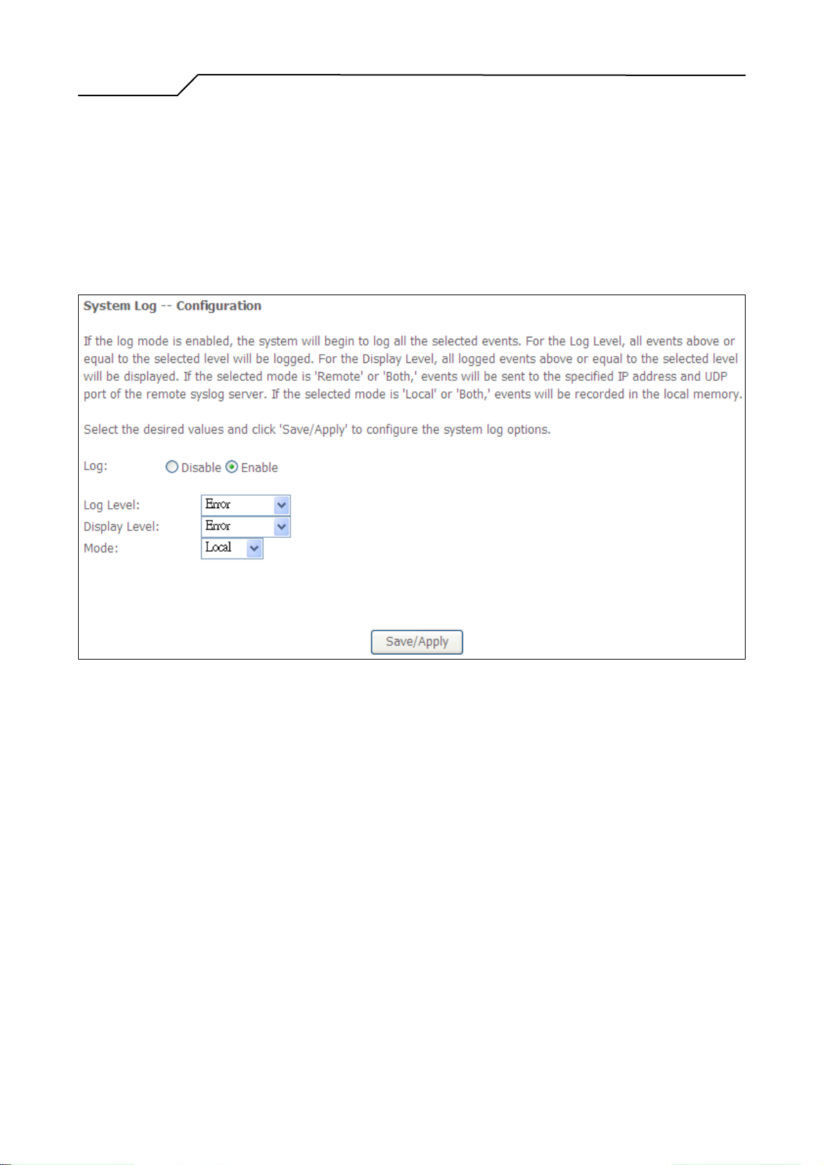
Click on “Configure System Log” to configure the log options. There are 8 events of
“Log Level” and “Display Level”: Emergency, Alert, Critical, Error, Warning,
Notice, Informational, and Debugging. If the log mode is enabled, the system will
- 57 -
Page 58
Manual Ver2.0
begin to log all the selected events. For the Log Level, all events above or equal to the
selected level will be logged. For the Display Level, all logged events above or equal
to the selected level will be displayed.
If the selected mode is “Remote” or “Both”, events will be sent to the specified IP
address and UDP port of the remote syslog server. If the selected mode is “Local” or
“Both”, events will be recorded in the local memory. Click on “Save/Apply” to save
the configuration.
Figure 71. Management – System Log Configuration
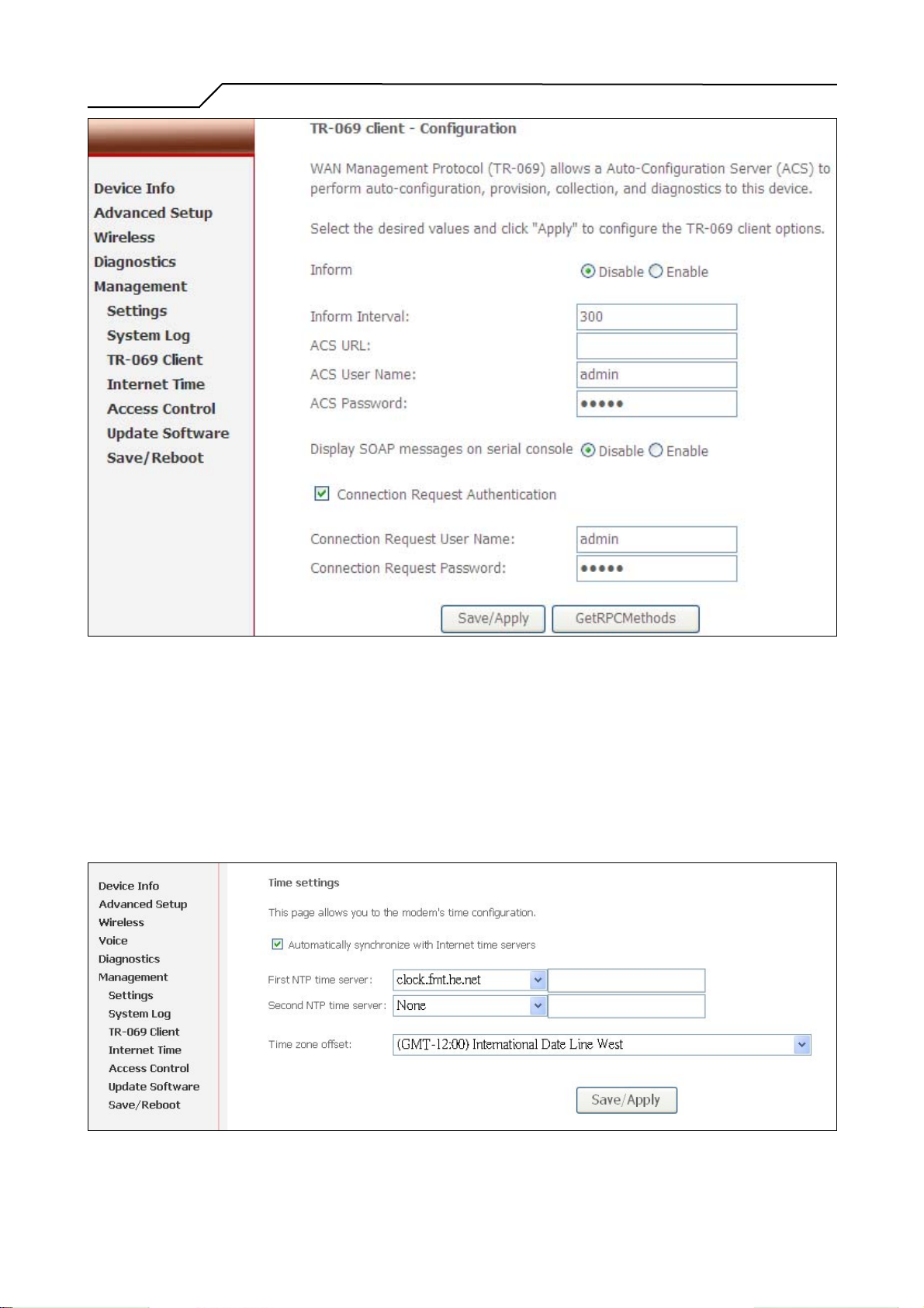
8.3 TR-069 Client
TR-069 is a WAN Management Protocol which allows an Auto-Configuration Server
(ACS) to perform auto-configuration, provision, collection, and diagnostics to this
device. You should have all the necessary information from your ISP if TR-069 is
implemented by your ISP.
- 58 -
Page 59
Manual Ver2.0
8.4 Internet Time
NWAR3600 can synchronize its internal time with Internet time server when available.
To enable this function, check “Automatically synchronize with Internet time servers”.
Select First and Second NTP time server from the pull down menu. Or select “Other”
and define your preferred NTP server. Choose the time zone from “Time zone offset”.
Click on “Save/Apply” to save the configuration.
Figure 72. Management – TR-069 Client
Figure 73. Management – Internet Time
- 59 -
Page 60
Manual Ver2.0
8.5 Access Control
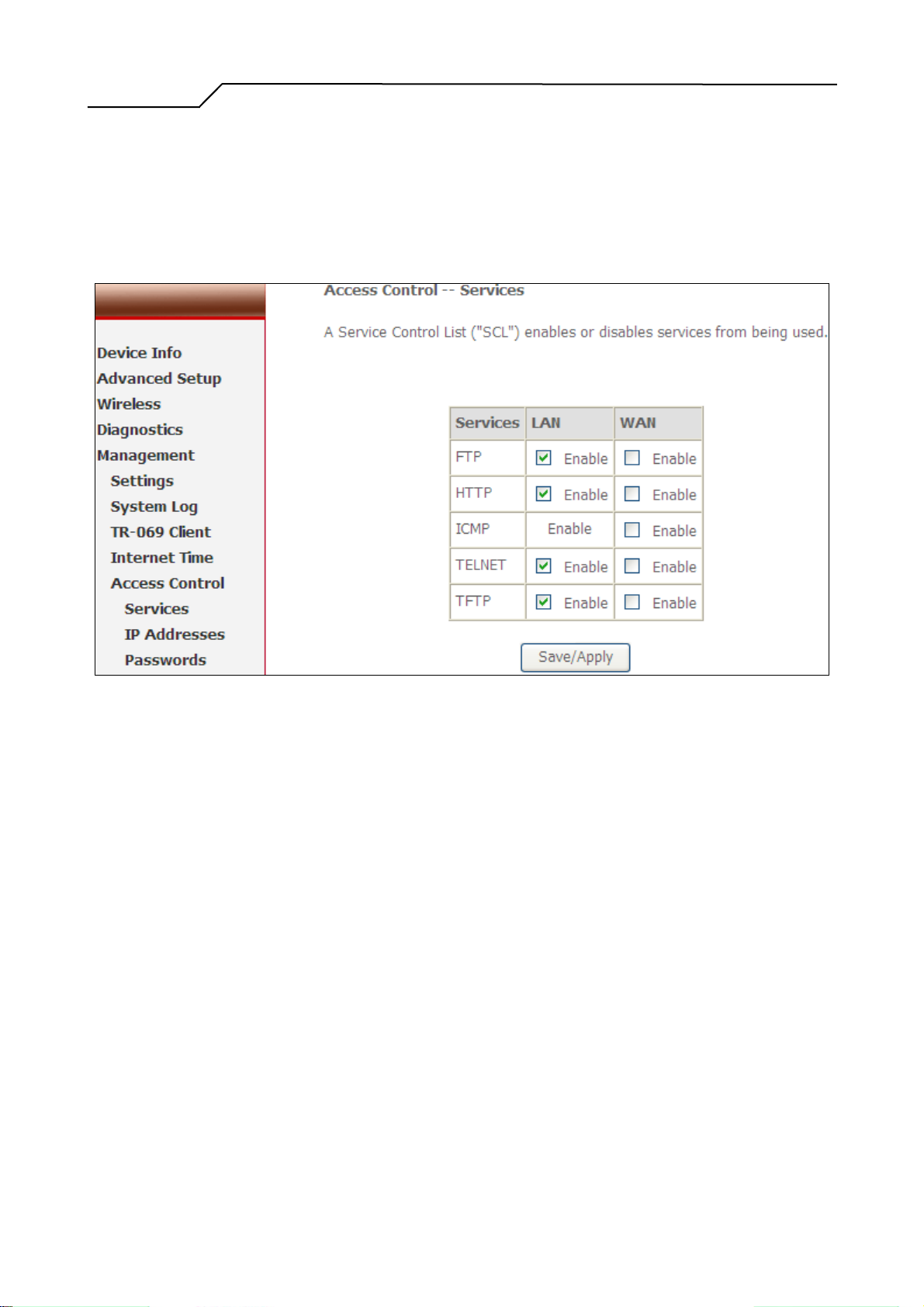
NWAR3600 browser management tool is protected by three categories: Services, IP
addresses, and Passwords. All three must be matched, if configured, to gain access to
the management tool.
All services are enabled from LAN side and disabled from WAN side by default.
Figure 74. Management – Access Control - Service
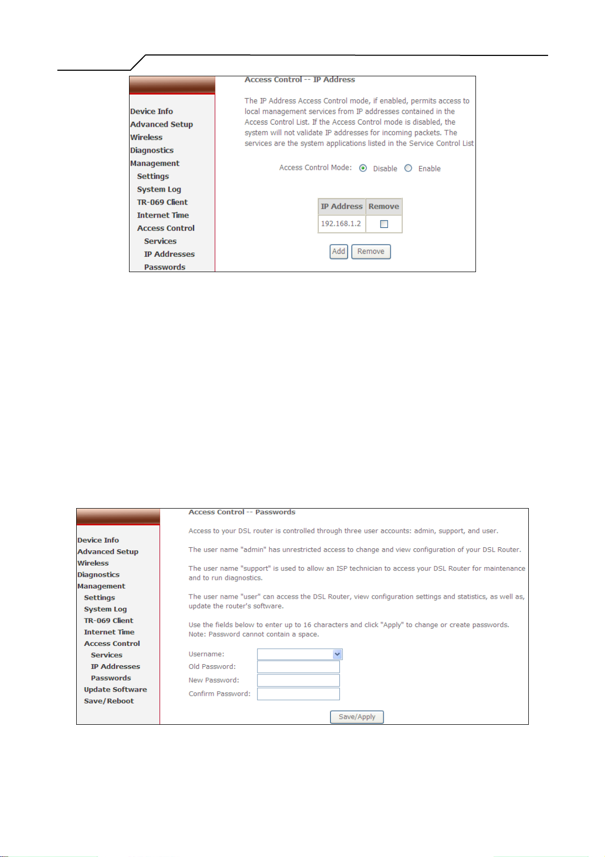
The IP Address Access Control mode, if enabled, permits access to local management
services from IP addresses contained in the Access Control List. If the Access Control
mode is disabled, the system will not validate IP addresses for incoming packets. The
services are the system applications listed in the Service Control List.
Click “Add” to add an IP address to the Access Control List. To remove, mark the
Remove option of the specified IP address, then click “Remove” to remove the IP
address from the Access Control List. Up to 16 hosts can be configured here.
- 60 -
Page 61
Manual Ver2.0
Figure 75. Management – Access Control – IP Addresses
Access to your router is controlled through three user accounts: admin, support, and
user.
admin: has unrestricted access to change and view NWAR3600 configuration.
support: is used to allow an ISP technician to access NWAR3600 for maintenance and
to run diagnostics.
user: can access NWAR3600 to view configuration settings and statistics, as well as,
update NWAR3600 software.
Use the fields below to enter up to 16 characters and click “Save/Apply” to change or
create passwords.
Figure 76. Management – Access Control – Passwords
- 61 -
Page 62
Manual Ver2.0
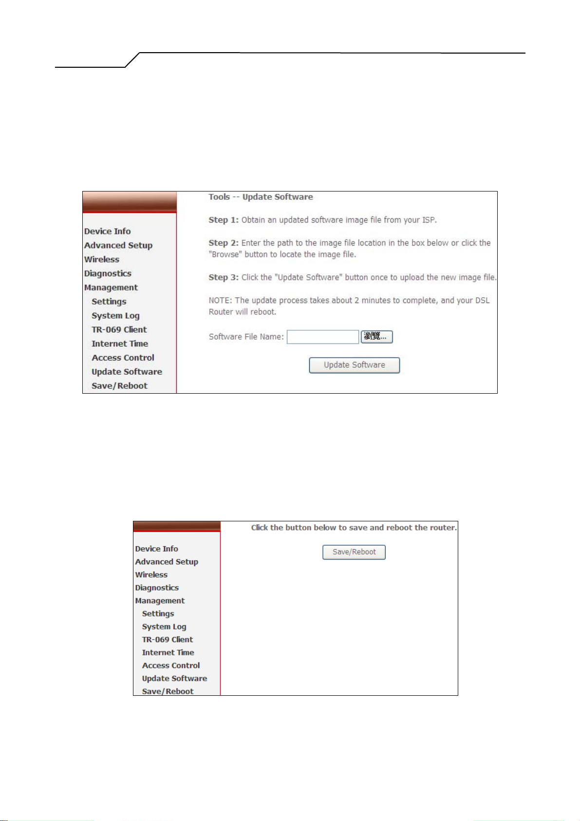
8.6 Update Software
The new software could be updated from the Local PC connected to NWAR3600 via
Ethernet cable. Click on “Browse” to locate the new software image file in the PC.
And then Click on “Update Software” to proceed the software update.
Note: The update process takes about 2 minutes to complete, and your NWAR3600
will reboot automatically.
8.7 Save/Reboot
Click “Reboot Router” to reboot NWAR3600. NWAR3600 would automatically save
the configuration before reboot, so that modified settings would take effect after
reboot.
Figure 77. Management – Update Software
Figure 78. Management – Save and Reboot
- 62 -
Page 63
Manual Ver2.0
9. Device Info
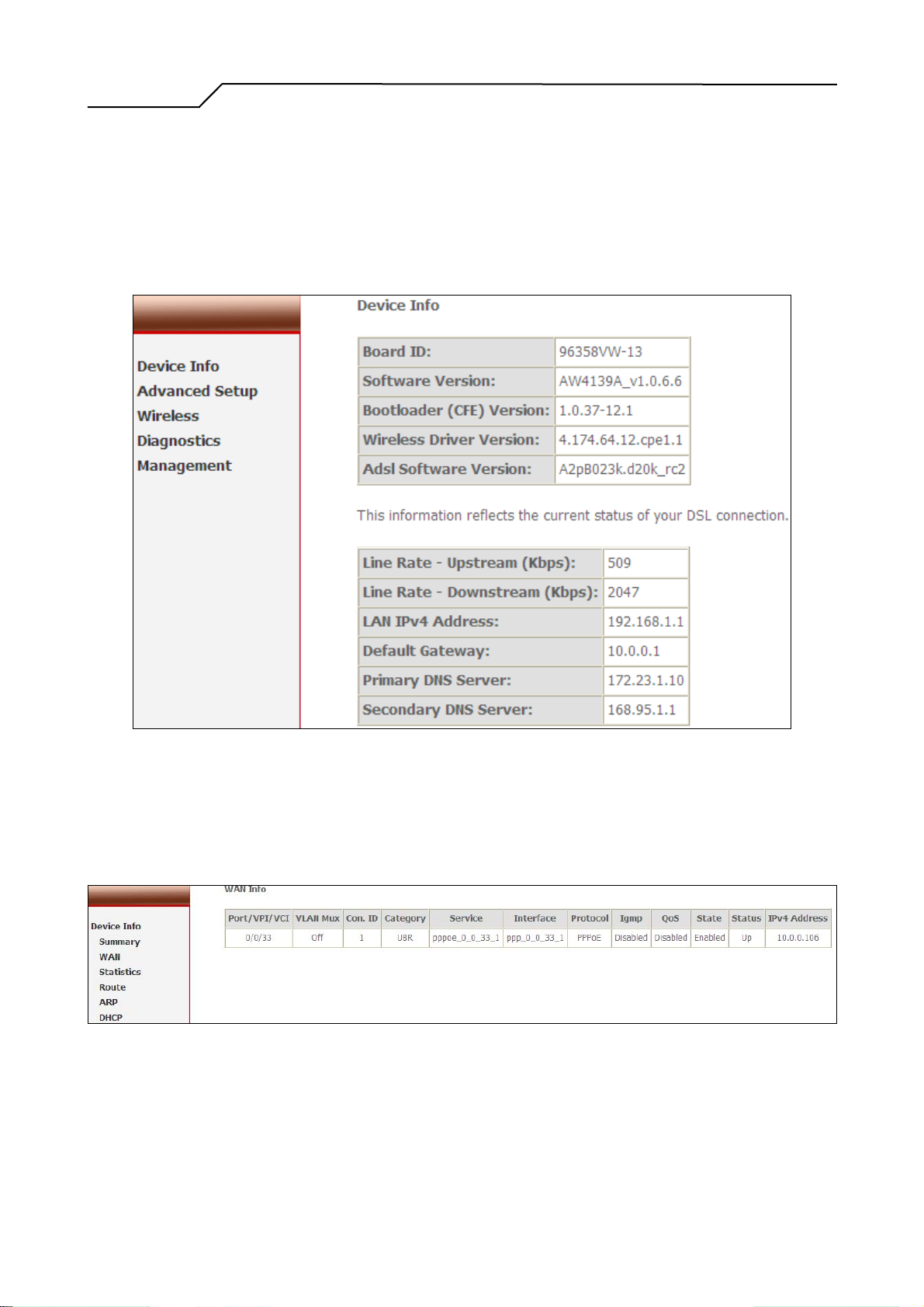
9.1 Summary
This page displays NWAR3600’s hardware/software information and DSL connection
status.
9.2 WAN
9.3 Statistics
Figure 79. Device Info – Summary
This page displays NWAR3600’s WAN interface information and connection status.
Figure 80. Device Info – WAN
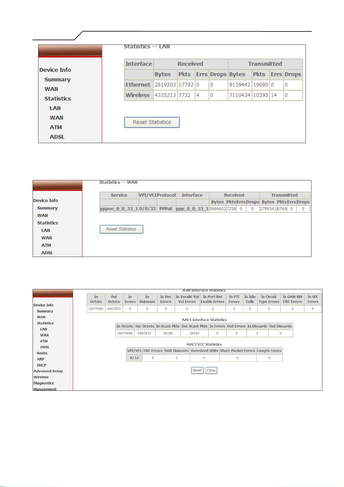
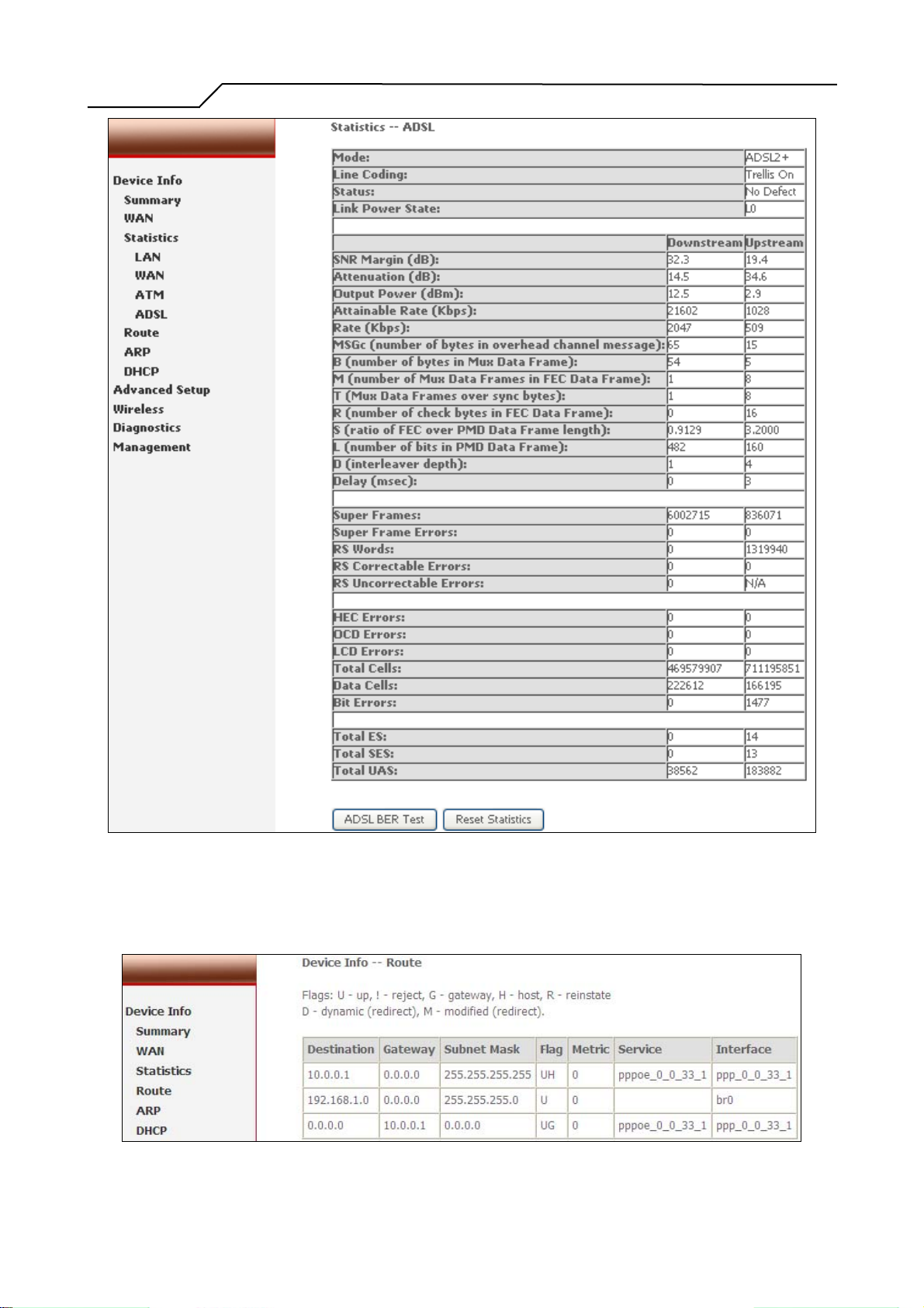
Statistics of NWAR3600 interfaces are displayed here including LAN, WAN, ATM
and ADSL.
- 63 -
Page 64
Manual Ver2.0
Figure 81. Device Info – Statistics – LAN
Figure 82. Device Info – Statistics – WAN
Figure 83. Device Info – Statistics – ATM
- 64 -
Page 65
Manual Ver2.0
Figure 84. Device Info – Statistics – ADSL
9.4 Route
This page displays NWAR3600’s routing table.
Figure 85. Device Info – Route
- 65 -
Page 66
Manual Ver2.0
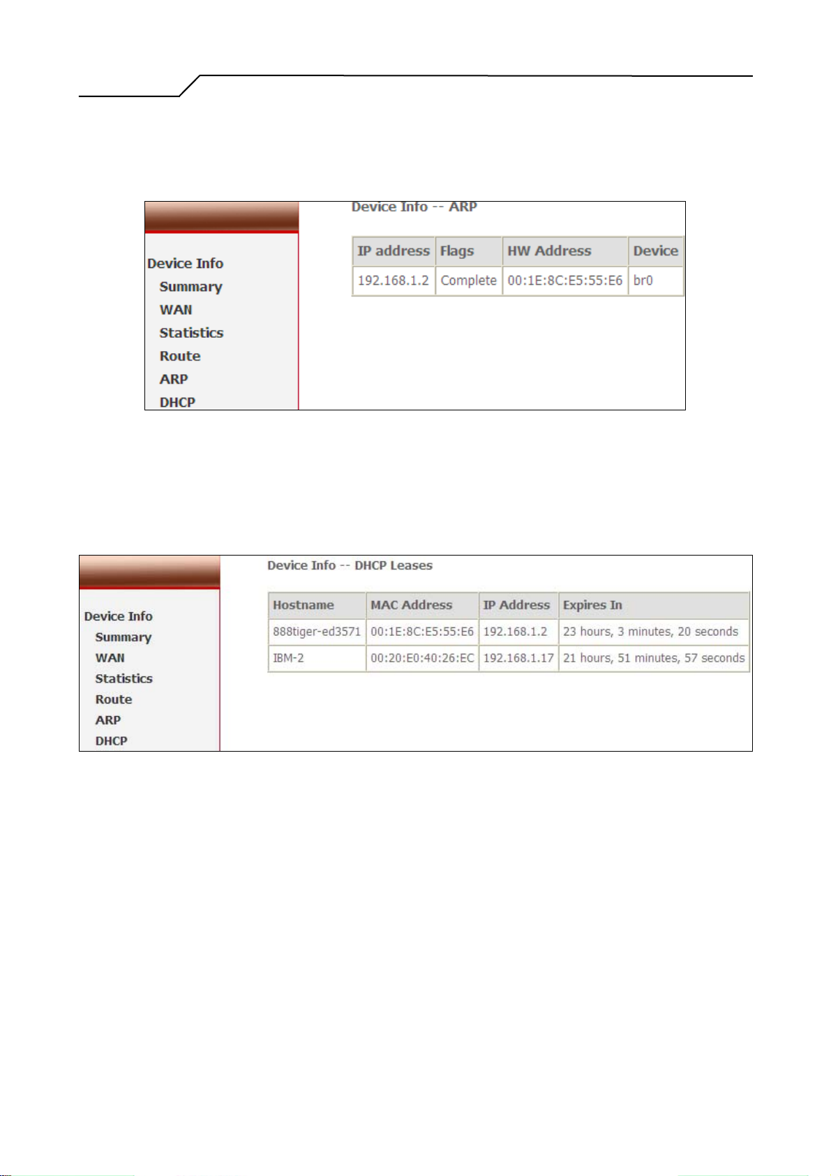
9.5 ARP
This page displays NWAR3600’s ARP table.
Figure 86. Device Info – ARP
9.6 DHCP
This page displays DHCP lease information.
Figure 87. Device Info – DHCP
- 66 -
 Loading...