

Page 1

ADT780 Pressure Controller
Page 2

Page 3
ADT780 Pressure Controller
User Manual
(Version No.: 201902V02)
(Please download the latest version via www.additel.com)
Additel Corporation.
Page 4

Page 5

Statement
This manual applies to ADT780 pressure controller series designed and produced by Additel Corporation.
This manual is subject to change without notice.
Page 6

Page 7

I. SAFETY NOTES 1
1.1 SAFETY AND CAUTION 1
1.2 LIABILITY 1
1.3 GENERAL SAFETY 1
1.4 WARNING
II. INTRODUCTION
2.1 OVERVIEW 2
2.2 FUNCTIONS 4
2.3 TECHNICAL SPECIFICATION 4
III. INSTALLATION 7
3.1 INSTALLATION 7
3.2 PRESSURE CONNECTION 7
3.3 ELECTRICAL MENU 9
3.4 COMMUNICATION MENU 10
3.5 PRESSURE MODULE CONNECTION 11
3.6 ELECTRIC SIGNAL MEASUREMENT AND BUS COMMUNICATION CONNECTION 12
IV. POWER-ON 14
4.1 POWER-ON SEQUENCE 14
4.2 LANGUAGE SETUP 14
4.3 DATE AND TIME SETUP 14
4.4 PRESSURE OUTPUT OF SETUP 15
V. OPERATION 15
I
Page 8
5.1 PRESSURE SETUP 15
5.2 UNIT SETUP 15
5.3 MEASUREMENT 15
5.4 CONTROL 16
5.5 EMPTY 16
5.6 PROGRAM SETUP 17
5.7 CURRENT/VOLTAGE MEASUREMENT 17
5.8 SWITCH MEASUREMENT 17
5.9 CONTROL SETUP 17
5.10 PRESSURE ZERO 19
5.11 DISPLAY SETUP 19
5.12 PRESSURE HEAD CORRECTION 19
5.13 DO CONFIGURATION 20
5.14 HART COMMUNICATION 20
5.14.1 Polling 20
5.14.2 Process Quantity 21
5.14.3 Setup 21
5.14.4 Diagnosis 21
5.15 PROFIBUS PA COMMUNICATION 23
5.15.1 Function Description 23
5.15.2 Equipment Description Document 23
5.15.3 Connection and Search 24
5.15.4 Process Quantities 24
5.15.5 Transmitter Operation 24
5.16 LEAK TEST 25
II
Page 9
5.16.1 Setup ……………………………………………………………………………………………………………………… 25
5.16.2 Execution ………………………………………………………………………………………………………………… 25
5.17 SWITCH TEST ………………………………………………………………………………………………………………… 25
5.17.1 Setup ……………………………………………………………………………………………………………………… 25
5.17.2 Execution ………………………………………………………………………………………………………………… 26
5.18 AUTOMATIC STEPPING …………………………………………………………………………………………………… 26
5.18.1 Setting …………………………………………………………………………………………………………………… 26
5.18.2 Execution ………………………………………………………………………………………………………………… 26
5.19 DECOMPRESSOR …………………………………………………………………………………………………………… 27
5.19.1 Setup ……………………………………………………………………………………………………………………… 27
5.19.2 Execution ………………………………………………………………………………………………………………… 27
VI. REMOTE COMMUNICATION ……… … … … … ……… … … … … ………… … … … … ……… … … … … … ……… 28
6.1 COMMUNICATION SETTING ………………………………………………………………………………………………… 28
6.1.1 Communication Setting –RS232 ………………………………………………………………………………………… 28
6.1.2 Communication Setting –WIFI …………………………………………………………………………………………… 28
6.1.3 Communication Setting – LAN …………………………………………………………………………………………… 28
6.2 COMMUNICATION COMMANDS …………………………………………………………………………………………… 29
VII. MAINTENANCE … … … … … … … … … … … … … … … … … … … … … … … … … … … … … … … … … … … … … … 2 9
7.1 SYSTEM AND PRODUCT INFORMATION ………………………………………………………………………………… 29
7.2 FIRMWARE UPDATES ………………………………………………………………………………………………………… 29
7.3 CALIBRATION ………………………………………………………………………………………………………………… 29
7.3.1 Internal pressure module and external pressure module calibration ……………………………………………… 30
7.3.2 Atmospheric pressure module and vacuum module calibration …………………………………………………… 33
7.3.3 Electrical signals measurement standards …………………………………………………………………………… 34
7.3.4 Atmospheric pressure module calibration ……………………………………………………………………………… 34
II I
Page 10
7.3.5 Self-tuning 35
7.4 UNINSTALLATION 35
7.5 CHANGEABLE PARTS 36
7.6 FUSE REPLACEMENT 36
7.7 FILTER REPLACEMENT 37
VIII. TROUBLESHOOTING 38
IX. APPENDIX 40
9.1 TRANSPORTATION AND STORAGE 40
9.1.2 Packaging 40
9.1.3 Transportation 40
9.1.4 Storage 40
9.2 PRESSURE UNIT LIST 40
9.3 SCPI List 41
IV
Page 11
I. Safety Notes
1.1 Safety and Caution
The mark on the controller means that the user must pay attention to operation instructions in the manual before
operation.
The mark on the controller means that high voltage may exist at the terminal or jack. Direct contact should be
avoided.
The mark in the manual refers to high voltage or high pressure where injury could occur.
Warning
The mark in the manual Indicates product damage may occur if operation instructions are not closely followed. Any
Caution
damage resulting in incorrect use of the product is not covered under the product warranty.
1.2 Liability
◆ Please note the following safety instructions;
◆ Please read the user manual before operation;
◆ Only operate with recommended media;
◆ Do not use the controller if damage is suspected;
◆ This product should be maintained by Additel or an authorized agent;
◆ Ensure the ground is connected with the AC power.
1.3 General Safety
◆ The controller should not be subject to strong vibration, impact, high temperature, high humidity or strong magnetic
influence;
1
Page 12
Do not use objects to clean or maintenance the controller that are not warranted;
The power voltage of the controller could cause physical injury. Even if the power supply is off, power could be
temporarily stored;
Ensure the controller is completely dry of any condensation that may have occurred.
1.4 Warning
High Pressure means the potential risk of high pressure air exist. The high pressure system can be installed and
operated by professionals only;
Pipes, valves and other facilities connected with the controller must be rated to the maximum pressure and the
sufficient safety redundancy considered;
Clean, dry and noncorrosive air shall be used. Oxygen should not be used as the control media;
Do not use in dusty, steamy or corrosive gas circumstances;
Do not use in explosive or dangerous environments;
Ensure the controller is not used under overvoltage condition;
When using nitrogen or inert gas as the media, the sufficient ventilation shall be ensured in the operation area.
II. Introduction
2.1 Overview
ADT780 Pressure Controller series can be used for a wide variety of application tests, calibrations and verifications.
ADT780 Pressure Controller has two range-dependent base units that determine the maximum pressures listed below.
Each base requires an external gas supply or Additel Electric Pump to control pressure.
● -0.1MPa ~ 7MPa; one pressure module with the range of 7MPa is embedded;
2
Page 13
● -0.1MPa ~ 21MPa; one pressure module with the range of 21MPa is embedded;
ADT780 can be equipped externally or internally with Additel 160A series of pressure modules.
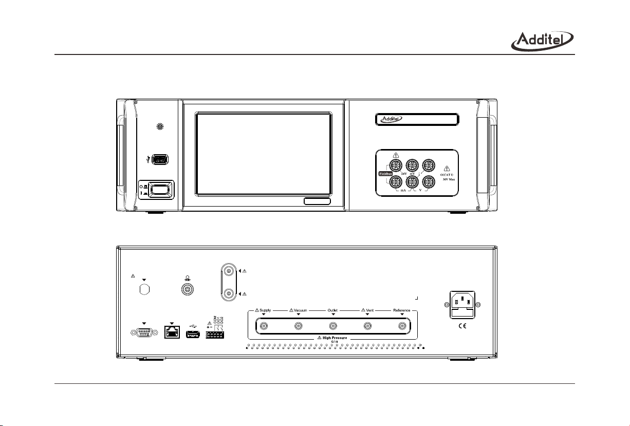
780 Pressure Controller
DC
Fig. 2-1 Basic Structure of ADT780 front panel
Logic Output
RS-232
Barometer
Exhaust
LAN
75W Max
(100-240) V
(50-60) Hz
Fuse T3.15A 250V
Fig. 2-2 Basic Structure of ADT780 rear panel
3
Page 14
2.2 Functions
Full auto control output pressure;
Can either be connected with pressure modules externally for control output ;
ADT780 output control defaults to the internal sensor when an external sensor is not connected;
ADT780 is embedded with 40Pa barometric pressure sensor (optional 11Pa) and can realize the absolute pressure and
gage pressure;
DC24V power output;
2-way DO digital output;
DC±30mA current measurement or voltage measurement (±30V, ±300mV);
Pressure switch capability;
800x480 color touch-screen display control operation and good HMI;
Two modes: controller mode and calibrator mode;
Main USB menu and configurable with a USB flash disk externally;
RS232, LAN and WiFi menus;
HART Profibus protocol calibrates HART equipment;
Profibus PA protocols;
WINCE operation system.
2.3 Technical Specification
Technical indexes:
4
Page 15
Power supply
Operation temperature
Working environment humidity
Display panel
Internal capacity
(100~240)VAC 50/60 Hz, maximum power consumption: 75 W
(0~50)
(-20~70)
<90%, non-condensed
7” color display, resolution: 800×480
15kg
3U cabinet (L×W×H = 419×440×132)mm
Nitrogen or dry and clean compressed air
Supply and outlet port: G1/8 female thread
110% ~120% of the pressure range
(-0.095~7) MPa or (-0.095~21) MPa
(-0.1~7)MPa
(-0.1~21)MPa
See ordering information for options and performance specifications. Control
sensor can be based on internal or external sensors.
See ordering information for options and performance specifications. Control
sensor can be based on internal or external sensors.
①
①
(60~110)kPa, accuracuy is 40Pa (11Pa is optional)
See Annex 9.2 for the pressure unit list
0.003% FS (stability based on % FS of control sensor)
500cc
Depending on the selected pressure control module
Two-way digital output (DO), programmable, source-less output, load-carrying capacity, 1A/DC24V
One-way source output, programmable, load-carrying capacity DC24V@200mA
Table 2-1 Technical Indexes
5
Page 16

The pressure range and control is determinant of the pressure module selected. Beyond its range, the measurement
value can be displayed only. 0.01%FS or 0.05% FS external connection modules can be selected.
The control stability is correspondenting with pressure range.
Barometer Measurement Uncertainty
Sensor/Mode
ADT160-02-CPXX
ADT160-01-APXXQ
Table 2-2 Technical indexes of electric signal measurement technology
Gauge
N/A
3 Pa ②
Absolute
40 Pa ①
N/A
40 Pa uncertainty (K=2) includes calibration uncertainty, linearity, and long term stability (<30 Pa per year). Barometer
range of 60 to 110 kPa.
Combined linearity, hysteresis, and repeatability. Add 3 Pa when used in gauge mode. When the absolute pressure type
of ADT160-01-APXXQ is switched to the gauge pressure type, the zeroing must be implemented by user. The ADT780
controller will clear the value difference between ADT160-01-APXXQ module and barometer module automatically.
Technical indexes of electrical signal measurement (ambient temperature 20 ±5 , yearly accuracy)
Measurement Range
(-30.0000~30.0000)V
(-300.000~300.000) mV
(-30.0000~30.0000) mA
If the switch has the tour inspection voltage, the voltage scope shall be DC 3V DC 24V.
Table 2-3 Technical indexes of electric signal measurement technology
Resolution
0.1mV
1µV
0.1µA
Accuracy
±(0.01%RD+1.5mV)
±(0.01%RD+15µV)
±(0.01%RD+1.5µA)
Note 1: When the ambient temperature exceeds the range from 15-25 , the temperature coefficient for voltage &
current measurement range: ±0.0005FS / .
6
Page 17
Note 2: Input characteristics:
(1) Voltage measurement range: input impedance >1MΩ,max. input voltage at the port: ±300VDC;
(2) Current measurement range: input impedance <10Ω, maximum input current at the port: ±1A DC.
◆ DC24V output, accuracy: ±0.24V, 50mA;
III. Installation
3.1 Installation
ADT780 pressure controller can used on a bench or rack
mounted. A rack mount kit may also be used to install the
controller on 19” (3U) cabinet. The rack mount kit includes
two fins and four installation screws. See Fig. 3-1:
When in operation gas may escape from “Vent” or
“Exhaust” ports and close contact should be avoided.
Warning
Ensure ventalation space near the bottom and rear
Caution
of the controller for heat dissipation.
3.2 Pressure Connection
Appropriate cautions and safety regulations should be observed when using gas supplies.
Warning
All pressure output is G1/8 and O-rings shall be used for sealing during connection.
Caution
See Fig. 2-3 for ADT780 pressure menu.
◆ Supply:
The Supply port is to connect a positive pressure supply to the controller. The supply should meet the following
requirements:
Fig. 3-1 Rack enclosure installation diagram
7
Page 18
1) Air or nitrogen must be clean and dry;
2) The air supply source pressure scope shall be 110-120% of the range of the pressure module connected with the
controller;
The maximum air source pressure shall be 120%FS of the upper limit of the range of the pressure module connected
Warning
with the controller. Otherwise, injury or equipment damage may occur.
It is suggested that the positive pressure air source shall be connected to “Supply” after passing through the air-liquid
Caution
separator.
◆Vacuum:
“Vacuum” is the port which provides vacuum source for the controller. If no vacuum source is required, the port should be
open to atmosphere.
The controller is embedded with a vacuum switch solenoid valve. When the valve releases pressure from the higher
pressure to the lower pressure, gas will be exhausted from “Exhaust”. The controller can control the solenoid valve to
choose “Vacuum” only if the vacuum pressure is required.
Positive pressure applied to the vaccum port may result in injury or equipment damage.
Warning
◆Outlet:
Outlet" is the pressure output /measurement menuport. Under the measurement mode, the outlet can be connected
with external pressure (please execute the empty function before connection). Under the control mode, the controller
outputs an adjustable pressure at the set point.
The “Outlet” pressure should not exceed the pressure module range. Otherwise, injury or equipment damage may occur.
Warning
When the controller is set to measure mode and the external pressure control exceeds 2MPa, the release valve
should be tightly screwed in the “Supply” port (As Fig 7-1). If there is a need to remove this release valve, please
Caution
loosen it firstly to relief the residual gas out.
8
Page 19

◆Reference:
ADT780 has a built-in barometer which enables gauge and absolute pressures types without connection to the
reference port.
◆Vent:
The “Vent” port is used for the venting of gas and disposing of any liquid or contaminants (through the Empty function)
so close exposure to the port should be avoided.
When the controller is venting, gas will vent from “Vent” port and close contact should be avoided.
Warning
◆Exhaust
“Exhaust” is used for exhausting gas. When the output pressure is higher than the barometric pressure, gas will
beexhausted from “Exhaust” under the control or exhaust mode. The exhaust speed depends on the “pressure change
rate” (see Chapter 5.9 Control Setup) and differential pressure. Gas exhausted at the high speed may make some noise
even though a noise reducing muffler is installed.
Gas may be exhausted from the “Exhaust” during the operation of the controller, close contact to the port should be
avoided..
Warning
◆Barometer
“Barometer” is used for measuring the pressure of the barometric pressure sensor. The “Barometer" is equipped with
a filter. The filter should be removed before it is connected to the standard pressure source during calibration.
3.3 Electrical Menus
The Electrical menu is located on the rear panel. See Fig 2-2.
◆ Power Supply Menu:
Operators must be familiar with and abide by electrical operation regulations and relevant safety regulations.
Warning
9
Page 20

Operators must ensure the power supply system connected with the controller has the grounding safety protection.
Warning
The controller is equipped with a three prong AC power cord plug, including one safety grounding joint. The operator
shall connect the power plug to the three AC power supply socket, ensure proper grounding and confirm that the
connected AC power supply meets the requirement of the controller for power supply (90V~250V, 50/60Hz).
◆ DO menu:
The terminal V+ and the terminal V- are DC24V active output and the maximum load is 500mA. V+ is DC24V and V- is
GND for controlling the solenoid valve of the external filter (gas-liquid separator).
The terminals DO1, DO2 and COM are constant open node outputs of two groups of inactive relays and the node
capacity is 1A/DC24V. See Chapter 5.10 DO Configuration for the definition of node functions.
3.4 Communication Menus
Communication menus of the controller are on the rear panel.
◆ RS232 menu:
RS232 menu of the controller is the main menu of DB-9 and works under slave mode for communication.
Pins are defined below:
Pin
Function
1 2 3 4 5 6 7 8 9
Table 3-1 Definition of RS232 pins
◆ LAN menu:
LAN is a standard RJ45 menu. The controller is allowed to access 10/100Mbps Ethernet to realize the quick
communication. Please refer to Chapter 6.1.3 Communication Setup-LAN for the parameter setup of LAN.
10
Page 21

◆ WIFI menu:
A WiFi unit is embedded above the USB menu on the front panel of the controller, supports 802.11b\g\n standard and
is used for accessing the wireless LAN. During installation, ensure the WiFi menu is not obstructed. See Chapter 6.1.2
Communication Setup-WiFi for the WiFi connection and parameter setup.
◆ USB A Menu:
A USB A menu is located on the front panel and rear panel of the controller for connecting U-disk, data input and output,
and upgrading firmware. See the relevant chapter for the detailed operation.
3.5 Pressure Module Connection
The pressure connection for the external pressure module (Model ADT160A) is located on the rear panel of the
controller. When connected, the controller switches the control mode to the external module to be used as the control
sensor. When the external pressure module is disconnected, the control mode switches to the internal pressure sensor
for control.
Logic Output
RS-232
Barometer
Exhaust
LAN
75W Max
(100-240) V
(50-60) Hz
FuseT3.15A 250V
Fig. 3-2 Rear view of the connection of the ADT160A pressure module
11
Page 22

When the internal ADT160A pressure module is used, ensure that the electric circuit and the air circuit of the external
ADT160A pressure module are disconnected at the same time. Otherwise, the external ADT160A pressure module
Warning
might be damaged.
3.6 Electric Signal Measurement and Bus Communication Connections
The controller supports current, voltage, switching measurement and Profibus communication functions (e.g. HART,
Profibus PA).
1 2 3
DC
4 5 6
Fig. 3-3 Electric signal measurement terminal diagram
I -
DC
I +
Calibrating terminals Function Description
Profibus communication and DC24V loop
power supply (maximum: 25mA)
DC24V power supply (maximum 25mA)
mV measurement
On-off measurement
Current measurement
Voltage measurement
Table 3-2 Electric signal measurement terminal introduction
Source
DC
V-
V+
Source
12
Fig. 3-4 Current measurement Fig. 3-5 Voltage measurement
Page 23

V+
DC
V-
Source
DC
Switch
Fig. 3-6 mV voltage measurement
Fig. 3-7 Switch measurement
+
Power
Fieldbus/HART Instrument
+
DC
-
DC
Fieldbus/HART Instrument
-
+
-
Fig. 3-8 Profibus connection (inner power supply)
Fig. 3-9 Profibus connection (external power supply)
Profibus /HART® supports connection using internal loop power and external loop power. When the external power supply
connection method is adopted, a 250Ω electric resistor shall be connected additionally.
Ensure the proper CAT rating to be used for voltage or current.
Warning
Do not contact any bare metal in the test loop.
13
Page 24

Signals exerted between terminals shall not exceed the rated value.
Warning
The maximum voltage exerted between terminals shall not exceed the peak value of 300V. Otherwise, the damage
could occur.
Warning
IV. Power-on
Before the controller is switched on, please check if power supply and air circuit are connected according to installation
Warning
requirements.
4.1 Power-on Sequence
Press the power button on the left side of the front panel. It may take approximately about 60s for the controller to power
on. The process is stated below:
1) Enter the booting menu;
2) The controller implements self diagnostics after waiting for a period of time;
3) The system enters the main menu.
4.2 Language Setup
Click the language setup icon on the setup menu and enter the language setup menu. You can switch to English,
Chinese, Germany, French, Italian, Spanish, Portuguese, Russia and Japanese menu. The new language setup is
effective after rebooting.
4.3 Date and Time Setup
Click the date and time setup icon on the system setup menu and enter the date and time setup menu.
◆ The valid date is from 2000-01-01 to 2099-12-31 and the valid time is from 00: 00: 00 to 23: 59: 59;
14
Page 25

◆ The controller accounts for leap year, leap month, second, minute and hour when it saves the setup.
4.4 Output of Setup Pressure
Click the main menu pressure setup value /current pressure value to set the target pressure. After checking, the controller
will adjust the pressure at the “Outlet” to the target value automatically.
Before generating pressure check to make sure the connections are properly made to the output port.
Caution
V. Operation
5.1 Pressure Setup
◆ S elect the pressure set value/current pressure on the main menu to set the target pressure;
◆ Select the icon or o n the menu to increase or decrease the set value by a set step;
◆ T he controller will switch to the control mode automatically;
◆ P lease input the pressure set value within the range indicated on the input menu.
5.2 Unit Setup
◆ S elect the pressure unit or pressure range on the main menu;
◆ T he unit selections are associated with the range and display resolution;
◆ C ustom units can be programmed;
◆ S elect the icon on the right corner of the menu to enter the unit editing and definition menu.
5.3 Measurement
◆ S elect the key “measurement” below the main menu to enter the measurement mode;
◆ I f measurement mode is selected when the controller is in control mode, the pressure control will stop immediately;
15
Page 26

◆ U nder the measurement mode, the controller measures the pressure at the “Outlet”.
5.4 Control
◆ Select the key “Control” in the menu of the controller to enter the control mode;
◆ After entering the control mode, the controller will adjust the pressure at the “Outlet” to the target value automatically;
◆ When the difference between the output pressure and the set pressure meets the requirement for the “control stability”,
the pressure display will turn green.
The supply of vacuum pressure must be greater than the desired set point or the controller will not be able to
properly control.
Caution
5.5 Empty
◆ Select the key “Empty” below the main menu to enter the fuction that pushes out any liquid or contaminents in the
controller;
◆ When the reset gauge pressure is controlled, after the controller achieves the set value of the “empty pressure”, it will
enter the empty mode automatically;
◆ After the pressure is vented, the output pressure at the “Outlet” drops to the barometric pressure and disconnect the
air supply and vacuum at the same time;
Please refer to Fig. 5-1 for the collection of liquid at the “Vent” if necessary.
Caution
Fig. 5-1 Liquid collection
16
Page 27

5.6 Program Setup
◆ Click the icon to increase pressure at a set value or step. When selected, the controller will enter the control
mode at once. If the current set value is 2 kPa and the step size is 1 kPa, after clicking the icon , the set value will
be 3kPa;
◆ Click the icon to reduce the set value. If the current set value is 2 kPa and the step size is 1kPa, after clicking the
icon , the set value will be 1 kPa.
5.7 Current/Voltage Measurement
Click the “Calibrator” icon in the function selection to enter the main menu of the calibrator.
1. Switch measurement items: current, voltage and mV measurement.
◆ I f the measurement value exceeds the measureable scope of the calibrator, “------” will be displayed and an alarm will
be given;
◆ S hort the measurement and select the reset icon.
2. Connection: refer to Fig. 3-4, Fig. 3-5 and Fig. 3-6.
5.8 Switch Measurement
Select the “Calibrator” icon to enter the main menu of the calibrator.
1. Switch measurement item: switch test.
2. After the switch is open or closed, the controller will record and display the pressure value of the set or reset.
3. Connection: refer to Fig. 3-7.
5.9 Control Setup
Select the “Control Setup” icon in the menu“System Setup”. menu
1. Pressure control velocity.
17
Page 28

The pressure velocity value can be adjusted as necessary.
2. Pressure control stability
◆I f the difference between the output pressure and the set pressure is within the range, it is deemed that the pressure is
stable. When stability is reached, the value will turn green and beep;
◆T he pressure control stability is expressed by the relative value of the pressure range.
3. Vent Pressure
After entering the “Vent” mode, the controller will adjust the output pressure toward barometric pressure. When the
output pressure is lower than the barometric pressure, the controller vent up to barometric pressure.
4. Pressure Type
◆T wo types: gauge pressure and absolute pressure;
◆A DT160A pressure modules are configurable for gauge pressure and absolute pressure. When the ADT160A module
is a gauge pressure type, absolute pressure = barometric pressure + gauge pressure;
◆W hen the ADT160A module is an absolute pressure type, gauge pressure = absolute pressure - barometric pressure.
When absolute pressure type is switched to gauge pressure type, the zero must be implemented.
Caution
5. Pressure resolution:
◆Q uartz pressure modules have resolution options of 5, 6 or 7, user selectable;
◆S tandard pressure modules have resolution of 4, 5 or 6 digits, user selectable.
6. Set Point Range
◆T his function is valid only if this parameter is enabled;
◆I nput an equal or smaller range according to the range of the controller as the upper and lower limits of pressure
control to protect devices under test which have a smaller pressure range than the controller;
◆T he setup will be memorized by the controller and still valid after rebooting;
18
Page 29

◆T he target value of the control pressure of the controller is limited to this requirement. Beyond the range, the controller
will ask you to input the upper and lower limits of the control range again.
7. Pressure Module
◆T here are two types of pressure modules: high and low range.
5.10 Pressure Zero
Select the key Zero below the main menu or click the “Pressure Reset” icon in the “System Setup” to enter the pressure
reset menu.
◆S elect pressure zero to zero the pressure reading;
◆F ollow the operation instruction on the menu;
◆W hen zeroing, the vent valve of the controller is open to the atmosphere;
◆T he gauge pressure module supports zero under the gauge pressure mode;
◆U nder the absolute pressure mode, the gauge pressure module supports zero. At this time, the gauge pressure is reset
to atmosphere;
◆U nder the gauge pressure mode, the absolute pressure module supports zero. At this time, the difference between the
barometric pressure measured by the absolute pressure module and the barometric pressure measured by the
barometric pressure is reset;
◆U nder the absolute pressure mode, the absolute pressure module does not support zeroing.
When the external ADT160A pressure module is connected, please ensure the module is open to atmosphere
to zero.
Caution
5.11 Display Setup
Screen luminance setup: 26 grades of screen luminance are optional. The higher the value, the brighter the screen.
5.12 Pressure Head Correction
19
Page 30

The distance from the middle of the internal ADT160A pressure module in the controller to the bottom is 60mm.
Pressure head correction is necessary when the device under test height is different from the internal ADT160A.
1. Figure out the correction value according to the density, height and gravity acceleration rate:
◆ When an external ADT160A pressure module is selected, please input the height difference between the device under
test and the external ADT160A pressure module;
◆ If the device under test is higher than the controller, input a positive height value;
◆ If the device under test is lower than the controller input a negative height value.
2. Set the constant correction value:
◆ The actual pressure value at the "Outlet" of the controller =target value + correction value.
5.13 DO Configurationc
◆ The controller provides two DO ports, i.e. DO1 and DO2;
◆ DO ports can be configured with 7 modes, including: closed, pressure stability, pressure measurement, pressure
control, pressure vent, overload pressure and pressure vacuum pump;
◆ When DO ports are closed, they always output low level;
◆ If DO ports are configured with the other 6 modes, DO ports will output high level when the controller stays at the
relevant state. Otherwise, they output low level.
5.14 Hart Communication
Select the "HART" icon menu to enter the Hart application menu.
5.14.1 Polling
1. Connection
See Fig. 3-8 for the internal loop power supply connection method. See Fig. 3-9 for the external loop power supply
20
Page 31

connection method.
2. Search
● Start polling after selecting internal or external loop power and resistance;
● Search the HART equipment from the address “0”. If the address “0” is searched successfully, the controller will
stop searching and display the HART equipment list. Otherwise, the controller will start to search from the address
“1” until it reaches “15”. After finishing searching, the controller will make a list of all searched HART equipment and
can support.
● In the searching process, you can stop searching by clicking the icon ;
● You can research again by clicking the icon after finishing searching;
● Select one HART device from the list of searched HART items. Click its icon to enter the HART menu.
5.14.2 Process Variable
● Select “Process Variable Selection” menu in the HART menu. Then, you can select the PV (Primary Variable),
current output AO, percentage, the 2nd variable, the 3rd variable or the 4th variable;
● At the upper right corner of the main menu of Hart application, the loop current always displays.
5.14.3 Setup
● Select “Setup” at the upper right corner of the main menu of the application to enter the setup menu;
● The equipment information, sensor information and equipment output information can be checked and modified.
5.14.4 Diagnosis
1. Current Loop Test
21
Page 32

● Enter the test value and press “√” to accept the value. The parameter range is (4-20)mA;
● A warning will be given if the value in tested is not acceptable;
● After the current value is written in successfully, the current measurement value is the actual value of the current
loop;
● Press the key “Fetch” to write the current measurement value into the virtual keyboard.
2. Electric Zero
● Select “√” on the electric zero to zero the value;
● Be sure that the current measurement value is close to the zero point or the zero may fail.
3. Current Adjustment
● Adjust the proportion coefficient of the current output loop of the transmitter to keep the AO value of the transmitter
the same with the actual output loop current;
● Provide the adjustment of the zero point (4mA) and the span point (20mA): when entering the adjustment point, the
controller will sets the transmitter as zero point or satisfaction point output automatically;
● The virtual keyboard input loop current measurement value can be used, the input range is (4-20)mA, or write the
current measurement value into the virtual keyboard by pressing the key “Fetch”;
● Press the key “√” to adjust the zero or span point according to the value on the display;
● In case of adjustment failure, the controller will give a warning.
4. Sensor Adjustment
● Adjust the PV of the transmitter to keep it the same with the actual output pressure;
22
Page 33

● Provide the low end (lower PV limit) and high end (upper PV limit) adjustment. When entering the adjustment point,
the upper or lower limit of the output PV range of the controller is set automatically. You may also select the output
icon of the controller and change the output pressure in the pop-up window;
● You can use the virtual keyboard to input the pressure measurement value or press the key “Fetch” to write the
current measurement value in the virtual keyboard directly;
● Press the key “√” to adjust the PV value according to the value on the virtual keyboard;
● In case of failure in adjustment, the controller will give a warning.
5.15 PROFIBUS PA Communication
Select the “Profibus PA” icon on the application menu to enter the Profibus PA menu.
5.15.1 Function Description
The controller can calibrate the PROFIBUS PA transmitter and set relevant basic parameters. It is helpful to understand
PROFIBUS PA terminology before performing a calibration on the device.
Note: The controller is used to provide pressure and communicate to the PROFIBUS PA transmitter. Therefore, in order
to avoid the damage to the control system of the process, the PROFIBUS PA transmitter should be separated
from the process before the controller is connected with the Profibus PA transmitter.
5.15.2 Equipment Description Document
The equipment description document is used for describing equipment parameters and parameter visiting method. By
means of parameter description, the user can operate all parameters of the PROFIBUS PA. The controller adopts the
special equipment description document and realizes the visit some parameters in Physical Block, transducer Block and
Function Block of the transmitter. The controller covers common transmitter description documents. If you need more,
please contact us.
23
Page 34

5.15.3 Connection and Search
● Please refer to Fig. 3-8 for the detailed connection method;
● You can start and stop searching by selecting the icon ;
● Select the PA equipment to be connected in the searched PA equipment list. Enter the main menu of Profibus PA after
successful connection.
5.15.4 Process Variables
Process variables are displayed on the main menu of Profibus PA. After selecting the key “Process Variable Selection”,
you can display and switch among PRIMARY_VALUE, SENSOR_VALUE, SECONDARY_VALUE_1, TRIMMED_VALUE,
SECONDARY_VALUE_2 and STATIC_PRESS_VALUE.
5.15.5 Transmitter Operation
1. Setup
● Select “Setup” at the upper right corner on the main menu to enter the setup menu.
● Visit and set relevant parameters on this menu, e.g. Physical Block, Transducer Block and Function Block. Before
some parameters are changed, relevant TARGET_MODE (OOS, Auto, Man, etc.) may also be changed. Please
change relevant parameters according to instructions in the transmitter manual.
2. Transmitter Trim
● Select the key “Trim” to enter the PA transmitter trimming menu.
● The transmitter can be trimmed in this menu. Before the transmitter trimming operation, please refer to relevant
instructions in the trim section of the transmitter manual.
24
Page 35

5.16 Leak Test
Select the icon “Leak Test” in the “Application” menu to enter the leak test application menu.
5.16.1 Setup
● Select “Setup” at the upper right corner on the main menu of the application to enter the setup menu;
● Set the pressure type, compression method, pressure unit, pressure setting, dwell time and test time;
● Dwell time: it is valid when the internal compression is selected. After the control output pressure of the controller
achieves the pressure setting and becomes stable, it switches to the measurement mode. At that time, the dwell time
counts down. After the dwell time achieves 0, the official test starts.
5.16.2 Execution
● Select the “Start” key for testing;
● The current leakage and leak rate is calculated in real time during the testing process;
● The curve on the right of the application menu reflects the real-time pressure value of the dwell time and test
time and it is possible to drag, amplify and contract the curve, etc.
5.17 Switch Test
Enter the switch test menu by selecting the icon “Switch Test” on the “Application” menu.
5.17.1 Setup
● Select “Setup” at the upper right corner on the main menu of the application to enter the setup menu;
● Set the pressure type, pressure unit, calibration scope, dead zone scope, setting point,permitted error and action type;
25
Page 36

5.17.2 Execution
● Select the “Test” key for testing;
● In the test process, you can select “Suspend” to suspend the test and select “Continue” to continue the test;
● After finishing the first test, select the “Test” key again for another test; Select the key “Finish” to end the test;
● The application program records the last three test points;
● After the test is over, you can check the process and result data.
5.18 Automatic Stepping
Select the icon “Automatic Stepping” on the “Application” menu to enter the automatic stepping application menu.
5.18.1 Setting
● Select the key “Setting” at the upper right corner on the application menu to enter the setting menu;
● Set the initial value, stop value, step length /stepping point, dwell time, operation mode, up and down and stepping
mode;
● The initial value and stop value of the step are not the same (initial value < end value: first up and then down; initial
value > end value, first down and then up);
● When the step length is not divisable by the whole section, the asymmetric method shall be adopted for generating
steps.
5.18.2 Execution
● Select the “start” key to start the step output;
● Manual operation: select “next point” to output each step sequentially. Select “last point” to go back to the last step.
26
Page 37

Select the key “Stop” for ending;
● Automatic operation: The controller will output each step automatically and sequentially according to the setting steps.
You can select the “Suspend” key to suspend the output, select “Continue” to continue the output and select “Stop”
to end the test.
5.19 Decompressor
Select the “decompressor” icon on the “Application” menu to enter the decompressor application menu.
5.19.1 Setup
● Select “Setup” at the upper right corner on the main menu of the application to enter the setup menu;
● Set the permissible tolerance, range and inspection points;
● The number of inspection points is 3-8.
5.19.2 Execution
● Select “Start” to start the test ;
● Leak test:
1) The application program will perform the leak test for 60s;
2) The pressure at the set point of the leak test is the maximum testing point pressure of the high pressure meter;
3) If you do not want to perform the leak test, select “Next” to skip it.
● Calibration of high pressure gauge:
1) Select “Next” in manual operation to output the pressure at each testing point sequentially;
2) After the pressure is stabilized, select to input the high pressure indication at the current test point.
● Calibrate the low pressure gauge: see the step for the calibration of the high pressure gauge;
27
Page 38

● Select “Finish” to check the testing result;
● Select “End” to quit the test;
VI. Remote Communication
6.1 Communication setting
Select the “Network Setting” icon at the “System Setting” menu, and enter the communication setting menu.
6.1.1 Communication Setting -RS232
Select “Serial Port” icon at the communication setting menu and enter RS232 setting menu. WIFI will be unavailable in
the case of RS232 communication.
● Baud Rate and Stop Bit can be set;
● The data bit is fixed as 8 digits.
6.1.2 Communication setting –WIFI
Select “WLAN Setting” at the communication setting menu and enter WIFI setting menu. WIFI will be unavailable in the
case of RS232 communication.
● In the case of using WIFI for the first time, you need to enter the “Advanced Options” menu to setup this function. In
the case of static IP, you should set the IP address, gateway and subnet mask; in the case of dynamic IP, you need
only to directly check “DHCP”;
● Check “WLAN”, you will open WIFI and start searching hotspots;
● Select “Wireless Hotspots”, and you may check all found hotspots and switch the hotspots;
● When connection is establishe this icon will appear at the top of the main menu.
6.1.3 Communication setting – LAN
28
Page 39

Select “Ethernet Setting” at the communication setting menu and enter LAN setting menu. In the case of static IP, you
shall set IP address, gateway and subnet mask; in the case of dynamic IP, you need only to directly check “DHCP”;
6.2 Communication commands
The controller follows SCPI (see the List of 9.3 SCPI).
VII. Maintenance
This Section stipulates system information, firmware updates, calibration, and routine cleaning and maintenance.
7.1 System and Product Information
◆ Select “System information” To view air pressure, vacuum pressure, build-in module pressure, external expanded
module pressure, atmospheric pressure and other information;
◆ Select “Product Information” in the “System Setting” menu to check information on host, controller, electrical logging,
bus module, etc.
7.2 Firmware upgrading
◆ The main program, controller firmware, measurement gauge firmware and bus firmware may be updated;
◆ The upgrade package must be put under the root directory of USB flash driver;
◆ The format of U disk is FAT16 or FAT32;
◆ After inserting U disk, select the icon “Service” at the “System Setting” menu and enter the password, “123456”to enter
into the service menu. Select “Upgrade by U Disk” to upgrade;
◆ Reboot the system after upgrading.
7.3 Calibration
◆ Calibrate the current/voltage measurement, build-in pressure module and external pressure module of the controller
regularly (i.e. by a recommended interval of 365 days) using the password, “123456”;
29
Page 40

◆ Provide factory calibration data function, and recover the calibration data to the factory status;
◆ Calibrate standard equipment of higher accuracy;
◆ After the last point of calibration, select “OK” and “Save”, and the new calibration data will become effective and used,
while the previous calibration data will be deleted permanently.
Please carefully operate the calibration functions of the controller, for inaccurate calibration may affect the accuracy
or sevicability of the controller.
Caution
7.3.1 Internal pressure module and external pressure module calibration
1. Set calibration points:
● In the case of positive and negative pressure multi-range, a three-point calibration shall be conducted with the
calibration point by default as the lower limit of the range, zero point and the upper limit of the range;
● In the case of negative pressure multi-range, a two-point calibration shall be conducted with the calibration point by
default as the lower limit of the range and zero point;
● In the case of positive pressure multi-range, a two-point calibration shall be conducted with the calibration point by
default as zero point and the upper limit of the range;
● All calibration points can be revised;
● The negative pressure calibration point shall meet the current ambient atmospheric pressure;
● Pressure generation can be performed through the controller or by an external device;
● Never impose pressure on the controller beyond the range.
2. Implementation standards:
● For calibration of the external pressure module, connect to the external module to the controller so the value is
30
Page 41

displayed;
● Pressure Generation:
1) Internal pressurization: means the pressure automatically driven to calibration points using the ADT780 controller;
2) External pressurization: Refer to the Outlet connection instructions of Section “3.3 Pressure Connection”. You
may use external standard pressure source to calibrate the controller sensor. During the calibration process, the
external pressure source provides standard pressure to all calibration points. The controller is measuring without
control. The controller automatically records the measurement values under standard pressure of all calibration
points to complete calibration.
● Internal pressurization:
1) Connect the digital standard to the “Outlet”; when calibrating external pressure module, connect the external
pressure module to “Outlet”;
2) Press “Start” to start the calibration;
3) By the prompt of the controller, the controller automatically enters the current pressure value of the calibration
points to the standard pressure gauge, enter the readings to the controller after both the pressure output and
standard readings become stable, and press “Next” to calibrate next calibration point;
4) After all calibration points are calibrated, press “Next” and you will be prompted to save the standard data or not.
● External pressurization:
31
Page 42

Standard pressurerelease valve
Fig 7-1 Connection of External Standard Pressure
1) When calibrating the internal pressure module, as shown by Fig-7-1, the standard pressure shall be connected
to “Outlet”, and a release valve shall be tightly screwed to “Supply”. when calibrating the external pressure
module, the standard pressure can be connected only to the external pressure module.
2) Press “Start” to calibrate;
3) By the prompt of the controller, the standard pressure source enters standard pressure of the current calibration
points to the controller. When the standard gauge readings and measurement value become stable, press “Next”
to calibrate next calibration point;
4) After all calibration points are calibrated, press “Next” and you will be prompted to save the standard data or not.
5) Before remove the release valve, please loose it firstly to exhaust the residual gas.
● At any time before the completion of calibration, you may press “Next” and return to the previous operation until
exiting the entire calibration function, where the calibration will not go to effect; if the calibration succeeds, the
current system date will be recorded as calibration date.
32
Page 43

7.3.2 Atmospheric pressure module and vacuum module calibration
ADT780 supports atmospheric pressure module and vacuum module calibration.
1. Set calibration points:
● The compound module requires a three-point calibration with the standard points by default as the lower limit of the
range, zero point and the upper limit of the range, of which the calibration pressure of the upper limit of range shall
be ≤600kPa;
● The atmospheric module requires two-point calibration with the standard points by default as lower zero point and
the upper limit of range, of which the calibration pressure of the upper limit of ADT780-7MPa shall be ≤10MPa,
and the calibration pressure of the upper limit of ADT780-21MPa ≤25MPa;
● All the calibration points can be revised;
● The negative standard points shall meet the current ambient atmospheric pressure.
2. Implementation standards:
● In the case of atmospheric pressure module calibration, the standard pressure shall be connected to “Supply”, and
in the case of vacuum module calibration, the standard pressure shall be connected to the “Vacuum”;
● Press “Start” to calibrate;
● By the prompt of the controller, the standard pressure source enters standard pressure of the current calibration
points to the controller. When the standard gauge readings and measurement value become stable, press “Next”
to calibrate next calibration point;
● After all calibration points are calibrated, press “Next” and you will be prompted to save the standard data or not;
before the completion of calibration, press “Previous” to return to the previous operation until exiting the entire
33
Page 44

calibration function, where the calibration will not go to effect; if the calibration succeeds, the current system date
will be recorded as calibration date.
7.3.3. Electrical signals measurement standards
1. Set standard points
● Treat the calibration points by default as -30mA, 0mA, 30mA, -300mV, 0mV, 300mV or -30V, 0V, 30V;
● The calibration points can be changed if necessary.
2. Implementation standards
● Press “Start” to calibrate;
● By the prompt of the controller, the standard current/voltage source enters standard current/voltage of the current
calibration points to the controller. When the measurement value becomes stable, press “Next” to calibrate next
calibration point;
● After all calibration points are calibrated, press “Next” and you will be prompted to save the data or not.
● At any time before the completion of calibration, you may press “Next” and return to the previous operation until
exiting the entire calibration function, where the calibration will not go to effect.
● If the calibration succeeds, the current system date will be recorded as calibration date.
7.3.4 Atmospheric pressure module calibration
The range of barometric pressure module is (60~110)KPa, accuracuy is 40Pa (11Pa is optional).
● Standard pressure connection to “Barometer”;
● Two-point calibration;
● Operate by the prompt of the controller.
34
Page 45

7.3.5 Self-tuning
Select “Self-tuning” at the calibration menu and enter the self-tuning menu.
Figure 7-2 Self-tuning Connection
● Before self-tuning, screw gas release fitting in Outlet port. During calibration, as Fig 7-2, srew gas release fitting tightly;
● Disconnect external module;
● Remove the external leakage with the pressure dropping rate <0.1kPa/s under ADT780-7MPa measurement and
< 1kPa/s under ADT780-21MPa;
● Connect to the external air source with the recommended air source pressure as 110% range upper limit, and
pressure source pressure shall not be less than 40% of the range upper limit;
● Implement the calibration by the prompts.
7.4 Uninstallation
In the case of installation displacement or packaging for transportation, the controller shall be operated by the following:
1) Release all pressure of the controller, and ensure no positive pressure and vacuum pressure in the controller;
2) Cut off the power connection (including positive pressure and vacuum);
35
Page 46

3) Turn off the power and then disconnect the power line;
4) Disconnect RS232 communication line, cyber line, DO connection line and electric signal test line;
5) Disconnect all pipes;
6) Remove the rack installation bolts for rack installation.
7.5 Changeable parts
Name / Order No.
Fuse
Filter (1220211087)
Table 7-1 Changeable Parts
Specifications and model
T3.15A/250V
50um
7.6 Fuse replacement
Refer to Table 7-1 for the specifications of fuse adopted by the controller. Fuse
change steps:
1. Press power switch, turn off the power, and disconnect the power line;
Even the power is disconnected, the leads of the power input filter may
Warning
also store dangerous voltage for internal capacity.
2. Remove the fuse box from the power input filter with ascrewdriver, and put in
new fuse as shown by Figure 7-3;
3. Restore the fuse box of new fuse to the power input filter;
4. Reconnect the power line, press the power switch and operate the controller;
5. Please contact Additel or the authorized agent, if the fuse blows immediately
after power connection.
36
Figure 7-3 Diagram of Fuse Replacement
Page 47

7.7 Filter replacement
If the gas circuit of the controller has two kinds of filters with models and order numbers shown by Table 7-1. If necessary
(such as due to jamming, erosion and rusting), please change the filter according to the following steps:
1. Release all internal pressure and disconnect the external air source;
2. Disconnect power of the controller;
3. Disconnect the external pipe connection;
4. Adopt special tools to remove the internal filters within all pressure interfaces, and put in new filters;
5. Restore the connection of air circuit and electric circuit.
Figure 7-4 Diagram of Filter Replacement
37
Page 48

VIII. Troubleshooting
If the failure cannot be fixed, please stop system operation immediately and contact the manufacturer or authorized
Warning
agent. To uninstall the system, please refer to Section 7.7 “Uninstall the System”.
Problem Cause/Solution
38
Blank display when plugged in and power
switch to ON
Current/voltage measurement readings turn
red or display “…”
No or sporadic DC24V output
The current voltage readings turn red
Unable to reach the set voltage value
Too much instability to reach the set
pressure value
Large air consumption
1. No power supplied or fuse blown;
2. Check the power and change the fuse (Refer to 7.7
“Change Fuse”).
1. Signal beyond the range;
2. Bring the signal in line with requirements.
1. PPTC response due to overload;
2. Technical specifications access load.
1. Pressure beyond the range;
2. Vent or lower input pressure.
1. Low positive pressure or vacuum air pressure;
2. Leakage; remove the leaks;
3. Conduct self-tuning.
1. Leakage; remove the leaks;
2. In micro-differential pressure application, “Reference”
port is not connected or well-sealed;
3. Conduct self-tuning.
1. Air circuit leakage; remove the leak.
Page 49

Problem Cause/Solution
In measurement mode, “Outlet”continues to
go up or down
Electric signals unable to be reset
Pressure measurement unable to reset
System prompt: The pressure module is not
properly connected
System prompt: Please adjust the air pressure,
too high for the present, to a proper range
System prompt: Please adjust the air pressure,
too low for the present, to a proper range
System prompt: The external module has not
been connected to the outlet
System prompt: Over output pressure
Table 8- 1 Co mm on Failures and H an dling Methods
1. Going up; the inlet pressure value is leaking;
2. Going down; the outlet pressure value is leaking.
1. The input signal is not zeroed; short the input and then reset .
1. “Exhaust” or “Vent” port is jammed;
2. Pressure module may need repair or recalibration.
1. Cut off the power for 10sec and then power again.
1. Lower the positive air source to the required range (refer
to 3.2 “Pressure Connection”).
1. Increase the air source to the required scope (refer to 3.2
“Pressure Connection”).
1. Connect the module to the pressure outlet.
1. Abnormal pressure control – lower or remove the pressure;
2. The pressure imposed on the Outlet is beyond the range:
lower externally imposed pressure;
3. Check pressure module.
39
Page 50

IX. Appendix
9.1 Transportation and storage
9.1.2 Packaging
Follow the packaging requirements before shipment to protect the controller against shock, moisture and water.
9.1.3 Transportation
Ensure safe handling with the controller shipment and mark all packages as “fragile”.
9.1.4 Storage
The controller shall be kept according to the following requirements:
1) Storage temperature: (-20~70) ;
2) Storage moisture: <90%;
3) Put it at clean and cool places, and avoid direct exposure to the sun;
4) No vibration.
9.2 Pressure unit list
40
S/N
Unit
Unit name supported by SCPI
Unit number supported by SCPI
S/N
Unit
Unit name supported by SCPI
Unit number supported by SCPI
9
Page 51

S/N
13
14
15
16
17
18
19
20
21
Unit
Unit name supported by SCPI
Unit number supported by SCPI
8
105
106
107
108
101
10
109
110
S/N
22
23
24
25
26
27
28
29
30
Unit
Unit name supported by SCPI
Unit number supported by SCPI
111
112
113
-1
-2
-3
-4
-5
-6
Table 9-1 Pressure unit list
9.3 SCPI List
Note: In this System, the pressure unit is always a separate parameter. The current/pressure unit can be a parameter together
with its value.
S/N
Command Description Parameter Return value
The command removes the following
register:
Standard event register;
* CLS1
Query event register;
_ _
Operational event register;
Status byte register;
Error queue.
41
Page 52

S/N
2
3
4
5
6
7
8
9
10
11
12
Command Description Parameter Return value
*ESE < en ab le value>
*ESE ?
*ESR ?
*IDN ?
*OPC
*OPC ?
*RST
*SRE < en ab le value>
*SRE ?
*STB ?
*WA I
Set the value of standard event enable
register
Read the value of standard event enable
register
Read the value of standard event register.
On execution of the order, the value of
standard event register will be reset.
In inquiring the apparatus marking, the
return data shall be divided into 2 parts:
a. Product series No;
b. Software version No.
After the equipment implements *OPC
command, set the “operation complete”
of standard event register at 1.
After *OPC? Order, return to 1.
Reset main program
Set the value of status byte enable register
Read the value of status byte enable
register
Read the value of status byte register
Wait for completion of operation.
< NRf>,0 -2 55
<NRf>, 0- 255
_
_
_
_
_
_
_
_
_
<Nr1>
Product series No.
and software Ver. No.
1
_
<Nr1>
_
_
_
<Nr1>
<Nr1>
_
42
Page 53

S/N
MEAS ur e[ :SCALar]
13
[:PR ES su re<n>]?
MEAS ur e[ :SCALar]:
14
CURR en t[ :DC]?
Command Description Parameter Return value
Pressure measurement. n valuing 1~6.
PRESsure1 means reading the pressure of
pressure module under control (the value
adjusted by air column under the currently
set pressure type);
PRESsure2 means reading the pressure of
internal module (as original value);
PRESsure3 means reading the pressure of
external module (as original value);
PRESsure4 means reading the pressure of
positive pressure module (as original value);
PRESsure5 means reading the pressure of
negative pressure module (as original value);
PRESsure6 means reading atmospheric
pressure
Current measurement. On receiving the
command, the controller sets the
measurement item as mA measurement,
conduct measurement, and return to the
measurement value. The current
measurement has only one range (-30~30)
mA, displaying the fixed bit width of 6.
_
_
Meas ur em ent
valu e: n am e of
unit
Meas ur em ent
valu e
43
Page 54

S/N
15
16
17
18
Command Description Parameter Return value
MEASure[:SCALar]:VOL
Tage[:DC]?
[<range>|MINimum|
MAXimum]
MEASure[:SCALar]:SWITch
[:CONNect]?
SENSe[:PRESsure]:
MODE ABSolute|GAUGe
SENSe[:PRESsure]:MODE?
Voltage measurement. On receiving the
command, the controller may switch the
range according to the parameters,
conduct measurement, and return to the
measurement value. The voltage
measurement has two optional ranges,
displaying the fixed bit width of 6.
Switch on-off status checking. On receiving
the order, the controller will set the
measurement item as switch measurement,
conduct measurement, and return to the
measurement value.
Set pressure type.
Read pressure type.
Measurement range: <numeric
_value> with unit or not. The
unit is V by default, if no unit
exists. If the value is (-0.3~0.3)
V, choose the measurement
range of (-300~300)mV with
other values falling in (-30~30)
V. MIN means the minimum
measurement range of (-300~
300) mV, and MAX the
maximum range of (-30~30)V.
If ignoring the parameters, we
will choose the measurement
range of (-30~30)V.
ABSolute
GAUGe
_
_
Measurement value
1: On
0: Off
_
Pressure type
44
Page 55

S/N
19
20
21
22
23
24
Command Description Parameter Return value
SENSe[:PRESsure]:DIGit4|
5|6|7|MINimum|MAXimum
SENSe[:PRESsure]:DIGit?
[MINimum|MAXimum]
SENSe[:PRESsure]:RANGe
[:UPPer]?
SENSe[:PRESsure]:RANGe
:LOWer?
[SOURce:]PRESsure
<pressure_value>
[SOURce:]PRESsure?
Set pressure display bit width. 7-bit width is
displayed only by connecting to quartz
sensor.
Read pressure display bit width.
Read the upper limit of measurement range
of the currently controlled module
Read the lower limit of measurement range
of the currently controlled module
Set targeted pressure value and output
pressure.
Read targeted pressure value.
Bit width: MIN shows the
currently supported minimum
bit width; MAX shows the
currently supported maximum
bit width.
MINimum shows the currently
supported minimum bit width;
MAXimum shows the currently
supported maximum bit width;
Ignore the parameters and
return to the currently set bid
width.
_
_
Pressure value: <numeric_
value> with the unit currently
set by the system.
_
_
Bid width
Upper limit of
measurement range;
name of unit
Lower limit of
measurement range;
name of unit
_
Targeted pressure
45
Page 56

46
S/N
25
26
27
28
29
30
31
32
Command Description Parameter Return value
[SOURce:]PRESsure:
SLEW <value>
[SOURce:]PRESsure:
SLEW? [LOWer|UPPer]
[SOURce:]PRESsure:
TOLerance <value>
[SOURce:]PRESsure:
TOLerance?
OUTPut[:PRESsure]:MODE
CONTrol|MEASure|VENT
OUTPut[:PRESsure]:
MODE?
OUTPut[:PRESsure]:
STABle?
CALCulate[:PRESsure]
:LIMit:LOWer <low>
Set pressure control rate.
Read pressure control rate.
Set pressure stability
Read pressure stability
Set working mode of pressure module
Read working mode of pressure module
Read pressure stability status
Set the lower limit of pressure
Pressure control rate:
<numeric_value> with the unit
currently set by the system.
LOWer: Read the lower limit
of the pressure control rate
UPPer: Read the upper limit
of the pressure control rate
Pressure stability
<numeric_value>,%FS
CONTrol represents control
mode;MEASure represents
measurement mode; VENT
represents venting mode.
Lower limit of pressure with the
unit currently set by the system
_
_
_
value; name of unit
_
Pressure control rate;
name of unit
_
Pressure stability
_
Working mode of
pressure module
1: Stable; 0: unstable
_
Page 57

S/N
33
34
35
36
37
38
39
40
41
Command Description Parameter Return value
CALCulate[:PRESsure]:
LIMit:LOWer?
CALCulate[:PRESsure]:
LIMit:UPPer <high>
CALCulate[:PRESsure]:
LIMit:UPPer?
CALCulate[:PRESsure]:
LIMit:STATe
<Boolean>|ON|OFF
CALCulate[:PRESsure]:
LIMit:STATe?
CALCulate[:PRESsure]:
LIMit:VENT <value>
CALCulate[:PRESsure]:
LIMit:VENT?
SYSTem:VERSion?
SYSTem:ERRor[:NEXT]?
Read the lower limit of pressure
Set the upper limit of pressure
Read the upper limit of pressure
Set whether the output range limit is
enabled.
Inquire whether the output range limit is
enabled.
Set venting pressure
Read venting pressure
Return to the SCPI Ver. No. followed by the
system.
Check next error item in the error queue,
and delete the item from the queue. The
Upper limit of pressure with the
unit currently set by the system
_
1,ON: Enabled
0,OFF: Prohibited
Venting pressure <numeric_
value> with the unit currently
set by the system
_
_
_
_
_
Lower limit of
pressure; name of
unit
_
Lower limit of
pressure; name of
unit
_
1: Enabled
0: Prohibited
Venting pressure;
name of unit
Ver. No.
Error information
_
47
Page 58

48
S/N
42
43
44
45
46
47
48
49
Command Description Parameter Return value
UNIT[:PRESsure] <unit_
name>|<unit_ID>
UNIT[:PRESsure]?
STATus:OPERation:
ENABle<enable value>
STATus:OPERation:
ENABle?
STATus:OPERation[:
EVENt]?
STATus:QUEStionable
:ENABle <enable value>
STATus:QUEStionable
:ENABle?
STATus:QUEStionable
[:EVENt]?
error queue can store 50 pieces of error
information. The last piece will be replaced
by -350“Queue overflow” in the case of over
50 pieces.System power off or *CLS order
can remove error queue.
Set pressure unit
Read pressure unit
Set operation status enable register
Read operation status enable register
Read the value of operation status register.
On execution of the command, the value of
operation status register shall be reset.
Set problem data enable register
Read problem data enable register
Read the value of problem data incident
register
Unit: It may be unit name as
quoted character string or unit
ID as numbers.
Enable value: <numeric_
value>,0-65535
Enabling value: <numeric_
value>,0-65535
_
_
_
_
_
_
Name of unit
_
<enable value>:NR1
<value>:NR1
_
<enable value>:NR1
<value>:NR1
Page 59

S/N
STATus:PRESet
50
Command Description Parameter Return value
Remove the value operation status enable
register and problem data enable register
Table 9-1 SCPI Summary
_
_
49
Page 60

Additel Corporation
2900 Saturn Street #B
Brea, CA 92821, USA
Phone: 714-998-6899
Email: service@additel.co m
website: www.additel.com
 Loading...