

Page 1

ADT22XA CALIBRATOR SERIES
Page 2

ADT22XA Series
Multifunction Process Calibrators
Please download the latest version from www.additel.com
Additel Corporation
Page 3
STATEMENT
Page 4

ADT22XA Series Calibrators..................................................................................................................................................... 1
1. Specifications......................................................................................................................................................................... 2
2. Safety Information.................................................................................................................................................................. 3
3. Accessories........................................................................................................................................................................... 4
3.1 Standard Accessories.......................................................................................................................................................... 4
3.2 Optional Accessories........................................................................................................................................................... 5
4. Cautions.................................................................................................................................................................................. 6
5. Technical Index....................................................................................................................................................................... 7
5.1 Working Environment.......................................................................................................................................................... 7
5.2 Storage Environment........................................................................................................................................................... 7
5.3 Electrical Parameters.......................................................................................................................................................... 7
5.4 Technical Parameters.......................................................................................................................................................... 7
6. Summary................................................................................................................................................................................ 15
7. Structure and Functions...................................................................................................................................................... 16
7.1 Basic Structure................................................................................................................................................................... 16
7.2 Introduction of Jacks Function............................................................................................................................................ 17
7.3 Key Functions..................................................................................................................................................................... 18
8. Basic Operation.................................................................................................................................................................... 19
8.1 Basic Mode......................................................................................................................................................................... 19
8.2 Measuring........................................................................................................................................................................... 20
Page 5

8.2.1 Millivolts Measurement................................................................................................................................................ 20
8.2.2 Volts Measurement...................................................................................................................................................... 20
8.2.3 Frequency Measurement............................................................................................................................................. 21
8.2.4 Pulse Counting............................................................................................................................................................ 21
8.2.5 Resistance Measurement............................................................................................................................................ 22
8.2.6 Switch Test................................................................................................................................................................... 22
8.2.7 Current Measurement.................................................................................................................................................. 23
8.2.8 Pressure Measurement............................................................................................................................................... 23
8.2.9 Thermocouple Measurement....................................................................................................................................... 24
8.2.10 RTD Measurement.................................................................................................................................................... 25
8.3 Sourcing........................................................................................................................................................................... 25
8.3.1 Changing the Source Value......................................................................................................................................... 26
8.3.2 Fine Tuning the Source Value...................................................................................................................................... 26
8.3.3 Reset............................................................................................................................................................................ 27
8.3.4 Step.............................................................................................................................................................................. 27
8.3.5 Ramp........................................................................................................................................................................... 29
8.3.6 Millivolts Source........................................................................................................................................................... 31
8.3.7 Volts Source................................................................................................................................................................. 31
8.3.8 Frequency Source....................................................................................................................................................... 31
8.3.9 Pulse Source............................................................................................................................................................... 32
8.3.10 Resistance Simulation............................................................................................................................................... 32
8.3.11 Current Source....................................................................................................................................................... 33
Page 6

8.3.12 Pressure Source(only available with pressure module).............................................................................................. 33
8.3.13 Thermocouples Simulation.......................................................................................................................................... 34
8.3.14 RTD Simulation............................................................................................................................................................ 34
8.4 Snapshot............................................................................................................................................................................. 35
9. Setup...................................................................................................................................................................................... 36
9.1 RS-232 Interface................................................................................................................................................................ 36
9.2 Snapshot Management....................................................................................................................................................... 36
9.3 Date and Time..................................................................................................................................................................... 37
9.4 Utilities................................................................................................................................................................................. 37
9.4.1 Scientific Calculator........................................................................................................................................................ 37
9.4.2 Simulate Transmitter...................................................................................................................................................... 37
9.4.3 Custom RTDs Library.................................................................................................................................................... 39
9.4.4 Thermal Calculator........................................................................................................................................................ 41
9.4.5 Pressure Leak Test(only pressure module is available)................................................................................................ 41
9.4.6 Unit Converters(Temperature, Pressure, Mass Flow and Volume Flow)...................................................................... 42
9.5 System Settings................................................................................................................................................................. 42
9.5.1 Alarm Settings............................................................................................................................................................... 42
9.5.2 Screen Settings............................................................................................................................................................. 42
9.5.3 Auto Power Off.............................................................................................................................................................. 42
9.5.4 Firmware Upgrade........................................................................................................................................................ 42
9.5.5 Restore Factory Settings............................................................................................................................................... 43
9.6 System Calibration.............................................................................................................................................................. 43
Page 7

9.7 24V dc Loop Power........................................................................................................................................................... 43
9.8 Display Language............................................................................................................................................................. 43
9.9 Help Guide........................................................................................................................................................................ 44
10. Task and AsCal.................................................................................................................................................................. 45
10.1 What is AsCal?................................................................................................................................................................ 45
10.2 Creating a New Task........................................................................................................................................................ 47
10.3 Delete/Erase Tasks.......................................................................................................................................................... 49
10.4 Select a Task to Be Calibrated......................................................................................................................................... 49
10.5 Viewing the Task Results................................................................................................................................................. 54
11. HART Communication(only HART is available).............................................................................................................. 56
11.1 Brief and Note.................................................................................................................................................................. 56
11.2 Connect to a HART Device.............................................................................................................................................. 56
11.3 HART Process Variables.................................................................................................................................................. 59
11.4 HART Diagnostics and Service........................................................................................................................................ 60
11.4.1 Loop Test..................................................................................................................................................................... 60
11.4.2 PV Zero Trim............................................................................................................................................................... 60
11.4.3 PV Calibration............................................................................................................................................................. 62
11.4.4 Special Calibration...................................................................................................................................................... 63
11.4.5 Output Trim................................................................................................................................................................. 64
11.5 HART Setup..................................................................................................................................................................... 65
11.6 Exit HART connection...................................................................................................................................................... 67
Page 8
ADT22XA Series Calibrators
Digital Pressure Modules
This user manual will guide you through the specifications and functions of the ADT22XA series calibrators
For further information please feel free to visit our website www additel com
1
Page 9

1 Specifications
Measure
Description
ADT221A Multifunction Temperature Calibrator
ADT222A Multifunction Process Calibrator
ADT223A Documenting Process Calibrator
Source
Description
ADT221A Multifunction Temperature Calibrator
ADT222A Multifunction Process Calibrator
ADT223A Documenting Process Calibrator
Other utility functions
Description
ADT221A Multifunction Temperature Calibrator
ADT222A Multifunction Process Calibrator
ADT223A Documenting Process Calibrator
mV
mV
HART
mA Hz Pulse
V
V mA Hz Pulse ohms RTDs TC
Pressure
Module
Utilities Task
Loop
Power
On off RTDs TC
ohms
Calibration RS232
Snap
shot
Note: ● :Available ○ U:Unavailable : CDP Series Intelligent Digital Pressure Modules
*
2
Page 10
2 Safety Information
◆
◆
◆
◆
3
Page 11
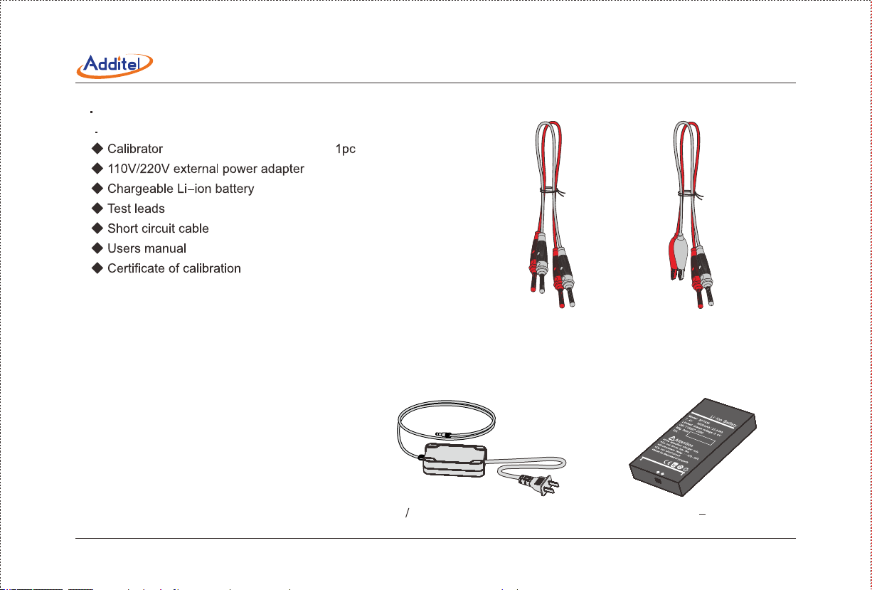
3 Accessories
3 1 Standard Accessories
1pc
1pc
3 sets (6 pcs)
1set (2 pcs)
1pc
1pc
X1
X3
Short circuit cable
Test leads
Chargeable Li ion battery110V 220V external power adapter
4
Page 12
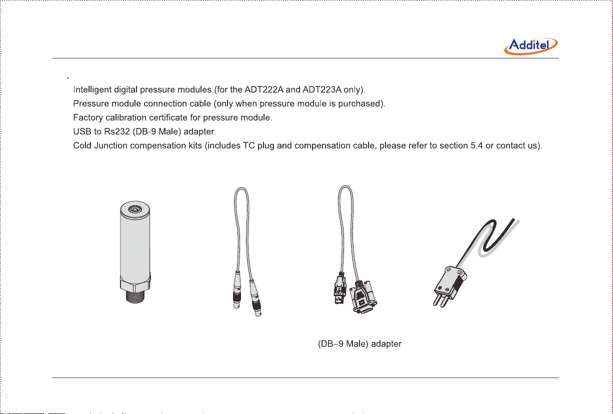
3 2 Optional Accessories
◆
◆
◆
◆
◆
Intelligent digital
pressure modules
Pressure module
connection cable
USB to RS232 Cold Junction
compensation kits
5
Page 13
4 Cautions
◆ Do not connect the test leads before toggling to another measurement or sourcing function
◆
◆ Regular cleaning and maintenance is recommended
If the calibrator exhibits any unusual behavior contact Additel Corporation to help troubleshoot the problem
◆
6
Page 14

5 Technical Index
Temperature: (-10 to 50)°C.
Relative humidity: <90% (Non-condensing).
Atmosphere pressure: (86 to 106) kPa
Temperature: (-20 to 60)°C.
Relative humidity: <90% (Non-condensing).
Power supply: polymer Li-ion rechargeable battery or 10VDC adaptor.
Charge mode: specified 10VDC adaptor (charging time is less than 4 hours).
Working time: more than 15 hours (The battery icon will blink when the power is low. It will power off automatically if no power
charge is left).
To get the best sourcing and measuring performance, the battery power supply is recommended.
Display: 3 5 inch high resolution TFT color screen.
Size: 192mm x 100mm x 52mm (L x W x H), Weight: 0 7kg.
Measure and source jacks: standard Φ4mm electrical jack.
Thermocouple measure and simulation (for cold junction and automatic compensation modes): flat mini-size connection.
Charger connection: standard Φ 2 1mm charger jack.
Rs232 interface: standard RS232-DB9 socket.
Pressure module: five-pole circular push-pull connector.
7
Page 15

Rs232 parameter: baudrate is 2400, 4800, 9600 or 19200, data bits is 8, stop bits is 1, address is from 1 to 121.
Real-time clock: three date formats are selectable. The year range is 2000 to 2099, and the time format is 24-hour.
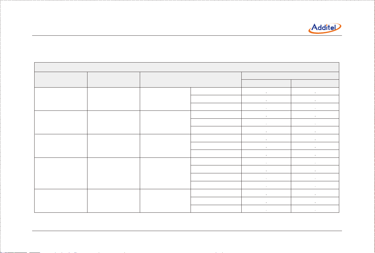
Electrical Signal Measure Specifications: (working environment: 20 5°C accuracy for one year)±
Table 5-1
Resistance
Function
Voltage DC
Current DC
Two wire
Three wire
Four wire
Two wire
Three wire
Four wire
Frequency
Pulse
-75 0000 to 75 0000 mV
-30 0000 to 30 0000 V
-30 0000 to 30 0000 mA
0 to 400 000
0 to 400 000
0 to 400 000
0 to 4000 00
0 to 4000 00
0 to 4000 00
1 to 50000 0 Hz
0 to 999999
Resolution AccuracyRange
0 1
0 1mV
0 1
1mΩ
1mΩ
1mΩ
10mΩ
10mΩ
10mΩ
0 1Hz
1
+3V to +24V
Note 1 : When ambient temperature is (-10 to 15°C and 25 to 50°C ) temperature coefficients are:
(1) Voltage, current measurement: ± (0 001 RD+0 0015%FS)/°C
8
0 01 RD + 3 75
0 01 RD + 1.5 m
0 01 RD + 1 5
0 02 RD + 0 02
0 02 RD + 0 02
0 01 RD + 0 02
0 02 RD + 0 2
0 02 RD + 0 2
0 01 RD + 0 2
0 005 RD + 1Hz
N A
Page 16
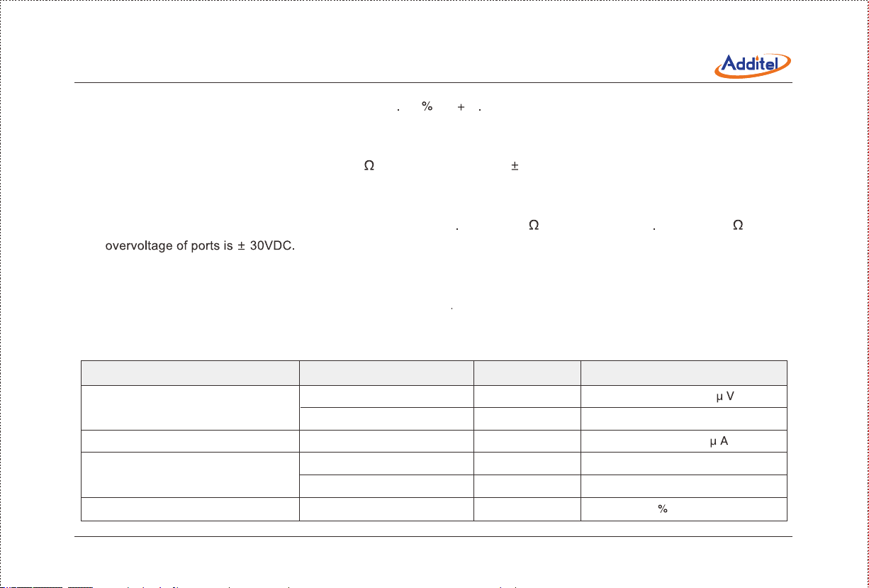
(2) 2-wire, 3-wire, 4-wire resistance measurement: ± (0 002 RD 0 001%FS)/°C.
Note 2: Input features:
(1) Voltage measurement: input impedance > 1M Ω ,overvoltage of ports is ± 300VDC.
(2) Current measurement: input impedance < 10 ,overvoltage of ports is 1A DC.
(3) Frequency, pulse measurement: Input impedance>500MΩ,square wave, low-level voltage < 0.3V, high-level voltage > 2V,
duty cycle is from 20% to 80%, overvoltage of ports is ±30VDC.
(4) Resistance, RTD measurement: excitation current is about 0 7mA at 400 range, and about 0 3mA at 4000 range,
(5) Thermocouple, RTD measurement temperature: To be decided by the accuracy of mV measurement, resistance
measurement, according to the International Temperature Scale of 1990 (ITS-90).
(6) Cold junction compensation range:-10 to 50°C,accuracy: ± 0 1°C,calibration is available.
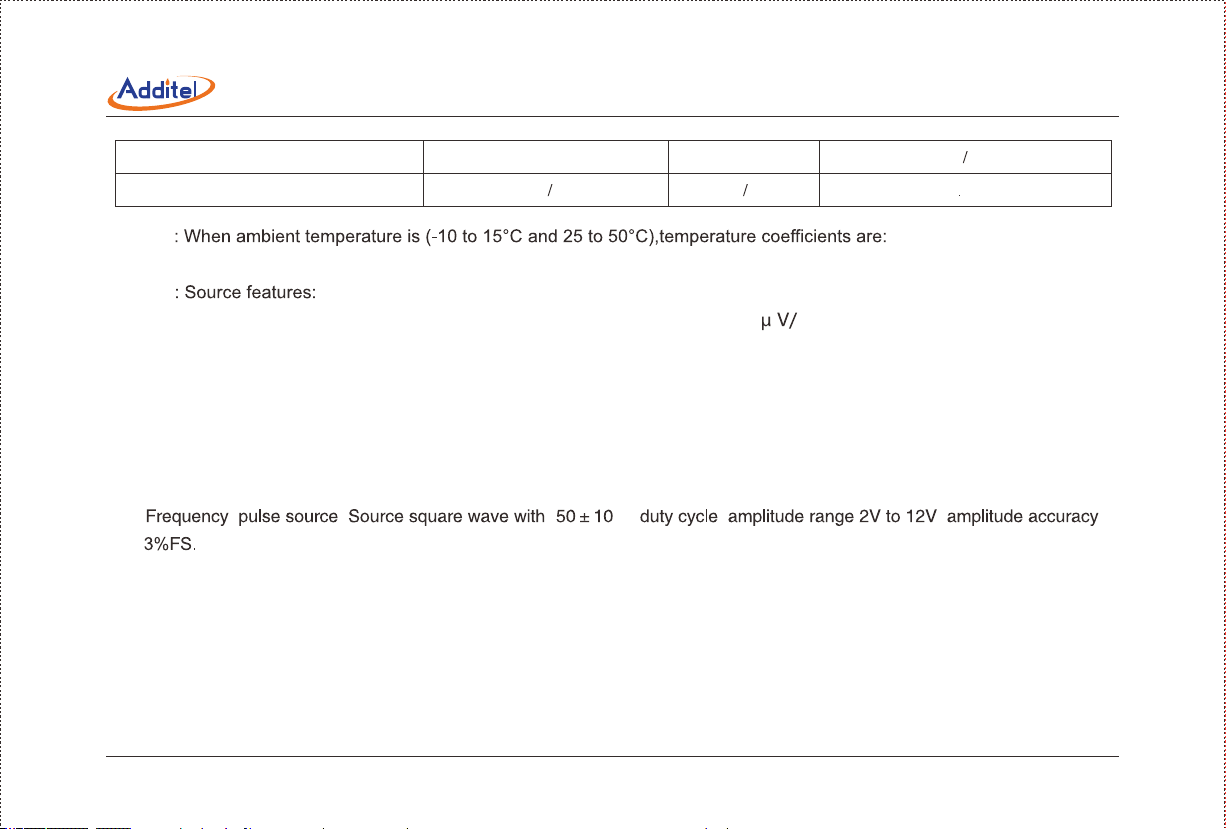
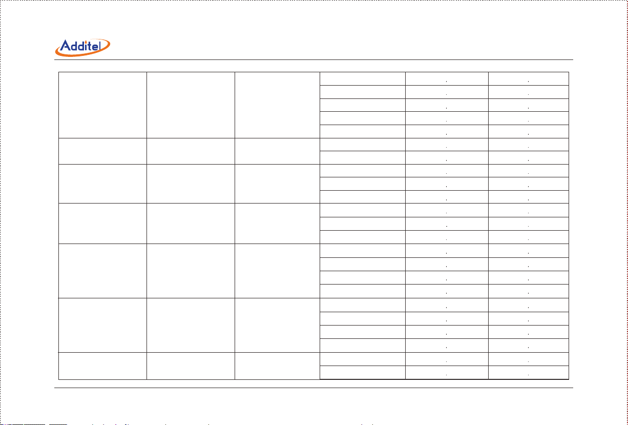
Electrical Signal Source Specifications: (working environment: 20±5°C,accuracy for one year)
Table 5-2
Function
Voltage DC
Current DC
Resistance
Frequency
-10.000 to 75.000 mV
0 to 12.0000 V
0 to 22.000 mA
1 to 400.00Ω
1 to 4000.0Ω
0 to 50000.0 Hz
Resolution AccuracyRange
100
1μV
0.1mV
1μA
10mΩ
mΩ
0.1Hz
0.02%RD + 4.25
0.02%RD + 0.6 mV
0.02%RD + 1.1
0.02%RD + 0.02Ω
0.03%RD + 0.4Ω
0.005 RD + 1 Hz
9
Page 17
Pulse
DC24V
0 to 999999
N A N A
1
N A
0 5V
Note 1
(1) Voltage, current, resistance source:(±0.001%RD+0.0015%FS)/°C.
Note 2
(1) Millivolts source: Max load capability is 1mA, load variance ratio less than 50 mA.
(2) 12V source: Max load capability is 5mA, load variance ratio less than 1mV/mA.
(3) Current source: Internal 24V power supply, max load capability is 20mA@1k Ω . External power supply, the max voltage is 36V.
(4) Simulating resistance: (1Ω to 110Ω) excitation current (0.6mA to 4mA), (110Ωto 400Ω) excitation current (0.3mA to
4mA), (400Ω to 1000Ω) excitation current (0.06mA to 1.5mA), (1000Ωto 4000Ω) excitation current (0.01mA to 0.6
mA). For (1Ω to 400Ω) range, 1mA driving current is recommended, and for (400Ω to 4000Ω) range, 0.1mA driving
current is recommended.
(5) , : ( )% , ,
(6) Loop 24V DC power: The maximum load current is 50mA, ripple<50mV.
(7) Simulating thermocouple, RTD source: To be decided by the accuracy of mV source and resistance source, according to
the ITS-90.
(8) All ports are short circuit protected.
(9) The maximum overvoltage of all the sourcing ports is±30VDC (less than 1 minute duration), the calibrator will be damaged
if this range is exceeded.
10
Page 18
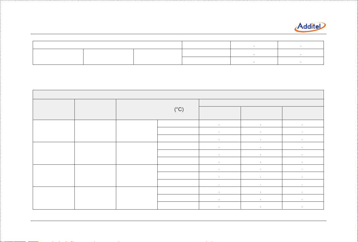
Thermocouple Measurement, Simulation and Source Accuracy. (Working temperature: 20°C ± 5°C)
Table 5-3
Thermocouple Measurement and Source accuracy
Measure and
Simulate
S
R
B
K
N
Temperature Range (°C)Standard
IEC 584
IEC 584
IEC 584
IEC 584
IEC 584 -270 to 1300
-50 to 1768
-50 to 1768
0 to 1820
-270 to 1372
Measure
-50 to 400
400 to 1000
1000 to 1768
-50 to 200
200 to 500
500 to 1768
50 to 450
450 to 800
800 to 1820
-250 to -200
-200 to -100
-100 to 600
600 to 1372
-250 to -200
-200 to -100
-100 to 1300
Accuracy(°C)
1 0 1 1
0 7
0 6
1 0
0 4
1 5 1 6
0 4
Source
0 60 6
0 8
1 41 4
0 60 6
0 7
3 83 8
0 90 9
0 70 7
1 1
0 5
0 30 3
0 50 4
0 60 5
0 5
11
Page 19
E
J
T
C ASTM E988 0 to 2315
D ASTM E988
G ASTM E1751 0 to 2315
L DIN 43710 -200 to 900
IEC 584
IEC 584
IEC 584
-270 to 1000
-270 to 1200
-270 to 400
0 to 2320
-250 to -200
-200 to -100
-100 to 0
0 to 700
700 to 1000
-210 to -100
-100 to 1200
-250 to -200
-200 to 0
0 to 400
0 to 1000
1000 to 1800
1800 to 2315
0 to 100 0 50 5
100 to 1100 0 50 4
1100 to 2000 0 90 6
2000 to 2320 1 30 9
0 to 200 2 42 4
200 to 400 0 50 5
400 to 1400 0 50 4
1400 to 2315 1 00 7
-200 to -100
-100 to 400
0 2
0 4
0 2
0 7
0 70 6
0 30 3
0 20 2
0 30 2
0 4
0 30 3
0 40 3
0 90 8
0 4
0 2
0 50 5
0 9
1 41 0
0 30 2
0 20 2
12
Page 20
400 to 900
U DIN 43710 -200 to 600
-200 to 0
0 to 600
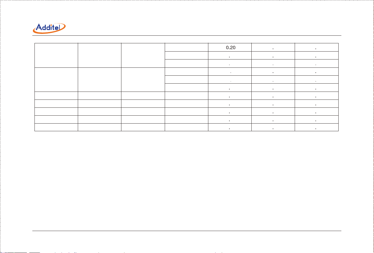
RTD Measure, Simulate, and Source Accuracy.(Working temperature:20°C ± 5°C)
Table 5-4
RTD Measurement and Source accuracy
Measure and
Simulate
Pt10(385)
PT100(385)
Pt100(3916)
Pt200(385)
IEC 751
IEC 751
IEC 751
IEC 751
Temperature RangeStandard
-200 to 850
-200 to 850
-200 to 850
-200 to 850
-200 to 200
200 to 600
600 to 850
-200 to 200
200 to 600
600 to 850
-200 to 200
200 to 600
600 to 850
-200 to 200
200 to 600
600 to 850
Measure
2W 3W
0 65 0 60
0 34
0 37
Accuracy (°C)
Measure
4W
0 720 82
0 820 96
0 10 15
0 160 26
0 20
0 10 15
0 160 26
0 200 33
0 32
0 410 51
0 480 61
0 30 2
0 40 4
0 30 2
Source
0 65
0 82
0 96
0 15
0 26
0 34
0 15
0 26
0 33
0 69
0 92
1 08
13
Page 21
Pt500(385) IEC 751 -200 to 850
Pt1000(385)
Cu10(427)
Cu50(385)
Cu100(385)
Ni120(672)
Ni100(618)
IEC 751 -200 to 850
IEC 751 -100 to 260
IEC 751 -50 to 150 -50 to 150 0 130 17 0 17
IEC 751 -50 to 150
DIN 43760
DIN 43760 -100 to 260
-100 to 260
-200 to 200
200 to 600
600 to 850
-200 to 200
200 to 600
600 to 850
-100 to 260 0 560 61 0 61
-50 to 150 0 09
-100 to 260 0 05
-100 to 260 0 06
0 32 0 22
0 1
0 27
0 12
0 07
0 08
0 16 0 36
0 54
0 270 40
0 05
0 100 2
0 14
0 67
0 25
0 42
0 54
0 12
0 07
0 08
14
Page 22
6 Summary
The ADT22XA series calibrators are high performance instruments, designed for the calibration and troubleshooting of variety
of process instrumentation and controls.
Features
1. Measure mA, millivolts, volts, ohms, frequency, pulses, switch, RTDs and thermocouples.
2. Source/simulate mA, millivolts, volts, ohms, frequency, pulses, RTDs and thermocouples.
3. Measuring and sourcing can be done at the same time.
( atented).
5. 24V DC loop power supply which is isolated from measuring and sourcing.
6. Supports square root transmitter.
7. Captures and saves screen snapshots.
8. Creates and runs AsCal (as-found as-left) tasks, record and document results.
9. High resolution, 3 5 inch TFT color screen.
10. HART communication capability.
11. Pulse frequency output.
12. Built-in utilities: Calculator, Transmitter Simulation, Custom RTDs Library, Pressure Leak Test and Conversion tools etc.
13. Easy to use: Smartphone-like menu and interface make the operation simpler and easier.
15
Page 23
7 Structure and Functions
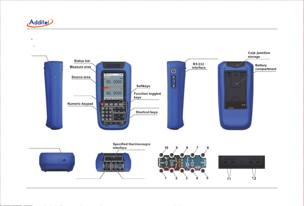
7 1 Basic Structure
“Protective cover”
Power key
Rechargeable jack
Pressure module
interface
223A
ADT223A
Documenting Process Calibrator
Powered by rechargeable battery
Navigation keys
or specified adapter.
S/N:
Additel Corporation USA ,
www additel com. .
Source jacksMeasure jacks
16
Page 24

7 2 Introduction of Jacks Function
Table 7-1
Jacks
2 & 9
2 9 & 10
1 2 9 & 10
1 & 10
4 & 7
4 & 5
3 & 8 Resistance source.
5 & 6
11
12
Pressure module interface
Rs232 interface
Rechargeable jack
① Voltage measurement, ② current measurement, ③ resistance measurement (2W),
switch, pulse measurement, frequency measurement.
Resistance measure (3W).
Resistance measure (4W).
HART communication (ADT223A only).
Voltage ource, current ource ( xternal ower upply), pulse ource,
frequency ource.
Current source ( nternal 24V c ower upply).
24V DC loop source.
Jack for thermocouple measurement. The calibrator can provide automatic cold junction
compensation function when this jack is used.
Jack for simulating thermocouple. The calibrator can provide the automatic cold junction
compensation function when this jack is used.
Connection for Intelligent Digital Pressure Modules.
Communicating with C.
Charger connection.
Note: To view the position of jacks1 - 12, please refer to section 7.1.
Introduction
17
Page 25

7.3 Key Functions
Table7-2
NO Key
1
2
3
4
5
6
7
8
9
10
11
12
13
14
15
Soft Keys
Numeric Keypad
18
Power key
Starts HART communications function (ADT223A only).
Selects the millivolts, volts, pulse or frequency.
Selects the resistance or switch test (measure function only).
Selects the RTD or thermocouple type.
Selects mA (current).
Selects pressure measurement or the pressure sourcing unction ( nly ressure odule s vailable).
Starts task management.
Enters the Setup menu.
Captures and saves snapshots (press and hold to access the snapshot management).
Exits the current page, cancels the operation. In the calculator page it, provides the clear function.
Confirms the selection or operation. In the calculator page, it is the equals (=) button.
Activates the measurement or sourcing windows, fine tunes the source value in Basic Mode.
Selects the item from the drop down list. In the calculator page, it provides the arithmetic buttons(+ - ÷ ×).
Performs the function defined by the context label.
Used whenever a numeric entry is required.
Instruction
Page 26

8. Basic Operation
The basic mode is the split screen that shows MEASURE and SOURCE areas
on the display(see figure 8.1). When returning from higher level operations (e.g.
Setup,Task, measuring options, sourcing options, etc), the calibrator will lso
eturn o he asic ode ith ast onfigured easurement nd ource.
In Basic ode, ou an ress he avigation eys o elect etween
he EASURE r OURCE reas. ou ill ee ither EASURE or SOURCE
highlighted, which means this display area is active. Function toggled keys( ,
, , , ) are used to select the MEASURE or SOURCE function.
In the Basic Mode you can perform the following:
Measure signals and zero the measured value.
Note: The calibration data(refer to section 9.6 system calibration)will be
changed once zero trim is performed, and can be restored manually.
Source/Simulate signals. Stepping, ramping(if allowed), set, and reset
source value.
Figure 8.1 The Basic Mode
19
Page 27

In the Basic Mode (as Figure8.1), if the measurement area is active, you can press the function keys ( , , , ,
) which will display the corresponding items.Anytime that you want to access the non-active area, press the desired function
key twice and the non-active area will become active (e.g. if the source area is active and you would like to change the measure
function from mA to V then press twice and the measure area becomes active and the list appears for you to hose
rom). o hange ny f easurement arameters, he easurement rea ust e n n ctive tate. reas an also become
ctive y electing he p/ own eys.
8.2.1 Millivolts Measurement
1. Figure 8.2 shows the millivolts measurement connections.
2. f he easurement s rea ctive, ress nce, r ress wice.
3. Press the avigation eys o elect V rom he ist, nd hen ress
Enter or Done to hange he easurement.
4. To improve measurement precision, you can short the millivolts input, and then
press Zero to clear the measured value.
8.2.2 Volts Measurement
1. Figure 8.2 shows the volts measurement connections.
2. If the measurement area is active, press once, otherwise press twice.
3. Press the navigation keys Up/Down to select the V item from the list, and then
ress or to hange he easurement.
4. o mprove easurement recision, ou an short he olts nput, hen ress Zero to lear he easured alue.
V
V
Figure 8 2 Millivolts or Volts
Measurement
Source
20
Page 28

3. Press the navigation keys Up/Down to select Hz from the list, then press Enter
Done
3. Press the avigation eys o elect Hz rom he ist, hen ress
Enter r Done o hange he easurement r ress Options o how ulse
ounting etup nterface.
4. The pulse counting option allows for the trigger edge to be selected
5. When the pulse counting is finished press to reset the counter
FRE Q
Source
Figure 8.3 Frequency Measurement
Source
Figure 8.4 ulse ounting
21
Page 29

8 2 5 Resistance Measurement
twice.
list, then press Enter or Done to change the measurement. You can also
press Options to show resistance measurement configuration interface.
press Zero to clear the measured value.
8 2 6 Switch Test
2. If the measurement area is active, press once, otherwise press
twice.
press Enter or Done to change the measurement.
4. Press View to view the switch test records (a maximum number of ten records
are shown). A record displays the tate f he witch ime, nd utput alue.
22
3W
DC Resistance
x10
x10 0
4W
x1
Figure 8 5 Resistance Measurement
Switch
Figure 8 6 Limit Switch Test
Page 30

1 Figure 8 7 shows the current measurement connections
2 If the measurement area is active, press once, otherwise press
twice.
3 Press the navigation keys to select mA from the list, then press
Enter or Done to change the measurement.
then press Zero to clear the measured value.
When a pressure module is connected, the pressure module icon will appear
in the status bar and beep at the same time. Figure 8.8 shows the pressure
measurement connections.
1 If the measurement area is active, press once, otherwise press
twice.
2 Press the navigation keys to select the pressure module from the
list, then press Enter or Done to change the measurement.
3 provides you with a list of pressure units to select from.
4. You can press Module to view the pressure module's information and change
the resolution.
5 To improve measurement precision, you can press to clear the
measured value.
Source
Figure 8.7 Current Measurement
223A
Measure
Source
Units
Module
Zero
Figure 8.8 Pressure Measurement
23
Page 31

The calibrator supports thirteen standard thermocouples, thermocouple types are
identified by character: S, R, B, K, N, E, J, T, C, D, G, L and U. Table 5-3 shows
the temperature ranges and accuracies of these thermocouples. Thermocouple
TC
measurement accepts two reference junction compensation methods: internal
reference mode or external reference mode. When using the internal reference
mode, the calibrator will automatically measure the temperature of cold junction
adjacent to the thermocouple jack. When using external reference mode, the
Thermocouple
reference temperature (value range: -10 to 50°C) must be entered manually
before measurement. Figure 8.9 shows the thermocouple measurement connections.
1. If the easurement rea s ctive, ress nce, therwise ress
wice.
2. You can press the navigation keys Up/Down to select TC from the list, then press
Enter or Done to begin measurement. Press Options to show the thermocouple
Figure 8 9 Thermocouple
Measurement
measurement setup interface. In the thermocouple measurement setup interface,
you can set the thermocouple sensor type, temperature units (°C, K, ℉ ) and reference junction compensation method.
3. hen easuring hermocouple, ou an ress Options o how he hermocouple easurement etup nterface.
4. o et igher emperature easurement recision, ou an zero he easured alue n he illivolts easurement.
24
Page 32

The calibrator supports 11 common RTDs shown in Table 5-4. In addition, calibrator
accepts 10 custom RTDs (to add a custom RTD please refer to 9.4.3). The calibrator
accepts RTD measurement inputs in two-wire, three-wire, or four-wire connections
as shown Figure 8 10 The four-wire connection can provide the most precise measurement
1. If the measurement area is active, press once, otherwise press twice.
2. Press the navigation keys Up/Down to select RTD from the list, and then press
Enter or Done to change the measurement or press Options to view the setup
interface.In setup interface, you can set the RTD sensor type, connections and
temperature units (°C, K, ℉ ).
3W
4W
RTD
the resistance measurement.
Figure 8.10 RTD Measurement
In the Basic Mode (Figure 8.1), if the source area is active, you can press ( , , , , ) which will display
the relevant source item list. If the measurement area is active, you can press the desired switch key ttwice which will activate
the source area. Or by pressing the navigation keys Up/Down, you can activate the source area.
25
Page 33

Notes
The input box will automatically close if left inactive for 15 seconds, Any new values will not go into effect.
Notes
26
Page 34

In the Basic Mode, volts, millivolts, frequency, resistance and current can
be reset by pressing the Reset softkey, which will set the source value to
zero.
In Basic Mode, the calibrator supports stepping the source value manually
or automatically. First you will need to configure the step settings. Each
source item (except pulse and pressure) has its own step settings. When
the source is active press Step to view the step setup interface. Figure 8.11
and Figure 8.12 are examples of a step configuration and results.
The start value cannot be the same as the end value, and the values cannot
exceed the output range.
Stepping supports three modes: engineering units, scale and step points.
The run mode and step time are relevant only for auto step. The range of
the step time is 1 to 3600 seconds.
Figure 8 11 Stepping Configuration
27
Page 35

Current(mA)
20
16
12
8
4
4
6
2
0
8 10 121416 1820222426
28 30
Time(S)
Figure 8 12 Step Results
1. If necessary, press the navigation keys Up Down until the source area is active.
2. Press Step to show the step setup interface, and configure these parameters as follows:
Start Value (in units).
End Value (in units).
Step Mode: Eng.Units, Scale or Step Points.
Step Size (Scale or Count, according to the Selection of Step Mode).
Trans Function: Linear or Square Root.
3. To complete the step settings, press Enter or Done , then the calibrator will Return to the Basic Mode and show the
main screen.
4. Press Manual to start manual stepping. The softkey label will changes to Next.
5. To advance to the next value press Enter or Next.
6. If you want to exit manual stepping, press Esc or Exit.
28
Page 36

1. If necessary, press Up/Down until source is active.
2. Press Step to view the step setup interface, and configure these parameters as follows:
Start Value (in units).
End Value (in units).
Step Mode Eng Units Scale or Step Points
Step Size (Scale or Count according to the Selection of Step Mode).
Run Mode (Repeat or Single shot).
Trans Function: Linear or Square Root
Step Time
3. To complete the step settings, press Enter or Done then the calibrator will return to the Basic Mode and show the main
4. Press Auto to begin automatic stepping, and the soft key label will change to Pause.
Press Pause to pause automatic stepping. The soft key label will change to Resume. Press Resume to continue
In the Basic Mode the calibrator offers the source value ramping function Ramping smoothly and continuously increases
or decreases the source value. The size of steps is determined by the start value, end value and the ramp time. Before ramping,
you need to configure the ramp settings Each source item (except pulse frequency and pressure) has its own ramp settings
When the source area is active press Ramp to view the ramp setup interface. Figure 8.13 and Figure 8.14 are examples of
the ramp setting and the ramp results.
29
Page 37

The Start value cannot equal the End value, and their values cannot exceed
the source output range.
Note
Current(mA)
20
16
12
8
4
10
0 5
15
20 25 303540 4550556065
70 75
Time(S)
Figure 8 14 Ramping Results
Proceed as follows to ramp:
Press Ramp to view the ramping setup interface, and configure the parameters
:
Start Value (in sourcing units).
End Value (in sourcing units).
Ramp Time: a rise time also a fall time.
30
Figure 8 13 Ramp Configuration
Page 38

Run Mode (Repeat or Single shot).
3. To complete the ramp settings, press Enter or Done then the calibrator will return to the Basic Mode showing the main
screen.
4. Press Enter or Start to begin automatic ramping, and the soft key label will change to Pause.
5 Press Pause to pause automatic ramping, and the soft key label will change to Resume. Press Resume to resume ramping.
If you want to exit automatic ramping, press Esc or Exit.
1 If the source area is active press once otherwise press twice.
2 You can Press the navigation keys Up/Down to select mV from the list, then press Enter or Done to change the source
to millivolts.
3
1 If the source area is active press once otherwise press twice.
2. ress he avigation eys o elect olts rom he ist, hen ress r o hange he ource o olts.
3
1. If the source area is active, press once, otherwise press twice.
2. Press the navigation keys Up/Down to select Hz from the list, then press Enter or Done to change the source to frequency
or press Options soft key to show the frequency source setup interface. In the frequency source setup interface, you can
set the amplitude.
31
Page 39

2. Press the navigation keys Up/Down to select pulse from the list, and then press Enter or Done to change the source to
pulse or press Options to show pulse source setup interface. In pulse source setup interface, you can set the triggering
edge, amplitude and frequency.
3. Refer to the sections 8.3.1 or 8.3.2 to select a method to change the source value according to your need, to start sourcing
pulse, you must press Start and the soft key label will change to Stop.
2. Press Up/Down to select the desired range (range 1 to 400Ω) from the lists, and then press Enter or the Done to change
the source to resistance simulation.
32
Page 40

1 Figure 8 15 shows the current source connections.
2. If the source area is active, press once, otherwise press twice.
3 Press the navigation keys Up/Down to select the mA with 24V loop power
or mA without 24V loop power from the list, then press Enter or Done to switch
source to current.
4. When sourcing current with internal power, the 24V DC loop power will indicate
it is on If the 24VDC power state is OFF, it will be automatically turned back
ON after switching source to current with internal power.
5. Refer to the sections 8.3.1, 8.3.2, 8.3.3, 8.3.4 or 8.3.5, select a method to
change the source value according to your need.
4. Press the navigation keys Up/Down to select the pressure module from the
list, then press Enter or Done to change the source to pressure.
supported by the calibrator.
mA
Ammeter
24V
Figure 8 15 Current Source
223A
Figure 8 16 Pressure Source
mA
33
Page 41

6. You can press Module to view and change information about the pressure
module.
or decreased with an external pressure generation device (such as Additel's
TC
8 3 13 Thermocouples Simulation
Refer to Table 5-3 for data about thermocouple types included in the calibrator.
2. You can press the navigation keys Up/Down to select the TC the list, and
6
5
then press Enter or Done o witch he ource o hermocouples imulation.
Press Options to show thermocouples simulation setup interface where you
can set he hermocouple ensor ypes, emperature nits (°C, K, ) nd
F
eference unction ompensation ethods.
3. Refer to the sections 8.3.1, 8.3.2, 8.3.4 or 8.3.5 to select a method to change
Temperature Indicator
Figure 8.17 Thermocouple Simulation
c
he ource alue ccording o our eed.
Refer to Table 5 4 for information about RTD (Resistance Temperature Detector) types supported
2. Press the navigation keys Up/Down to select RTD from the lists, and then press Enter or Done to switch the source to
RTD simulation or press Options to show the RTD simulation setup interface. where you can set the R TD sensor type
and temperature units (°C, K, ).
F
34
Page 42

In Basic Mode, you can press Save to capture a snap shot. When the snapshot is successfully saved to the memory, the
calibrator will display the save icon in the status bar and beep at the same time. For more details about snapshot please
refer to section 9.2 Snapshot Management.
35
Page 43

9 Setup
provides you with a help menu (as Figure 9-1).
While in the setup page, you can navigate to the various menus by using
the navigation arrows and pressing Select or Enter to choose the items.
9 2 Snapshot Management
Snapshot provides a paperless record of the display screen when you
press Save in Basic Mode. A snapshot includes: snapshot name, measuring
value,sourcing value, reference junction compensation temperature (for
thermocouples),and the loop power status and the system time.
9 3 Date and Time
To change the date and time of the calibrator, select the date and time item
on the Setup page and press Enter or Select.This menu allows for the date
and time to be changed and the time format to be modified if desired.
9 4 1 Scientific Calculator
Figure 9.1 Setup
36
Page 44

The transmitter is a device which can measure temperature, electrical signals and pressure, etc. Generating a signal according
to the measurement imposed.
The calibrator can simulate a transmitter. It can measure RTDs, thermocouples, frequency, volts, mA, ohms and pressure
(when the pressure module is connected), and output mA and volts signal.
After selecting simulate transmitter the Quantity page will appear and you can chose from various sensor types and the
transmitter output (as shown in Figure 9 2).
On the Range page, set the input range 0 to 200°C and the output range 4 to 20mA. Sometimes, it is necessary to set the
transfer function: Linear/Square root (as shown in Figure 9.3).
37
Page 45

Start
Caution
38
Figure 9 2 Simulate Transmitter Quantity Figure 9 3 Simulate Transmitter Range
Page 46

and Standard PRTs (standard platinum resistance thermometers).
The calibrator allows you to input the customized values, so you can measure temperature using every kind of RTDs and
Standard PRTs.
How to create a custom industry RTD?
To achieve higher precision with an RTD, IEC and ASTM standards specify a more complex polynomial curve fit that fine tunes the resistance-temperature relationship. One form of that equation is given here as below. The industry RTDs also
specify values for the constants R0, A, B, C (The C constant is only used for temperature less than 0°C).
How to create a standard PRT?
The Standard Platinum Resistance Thermometer (SPRT) Calibration Laboratory of the NIST Thermometry Group can
distinguish among the ITS-90 from the argon triple point (Ar TP, -189.3442°C) to the silver freezing point (Ag FP,
961.78°C) for the calibration of SPRTs.
The ITS-90 defines temperature through a set of specified thermometric fixed points, interpolation instruments, and
interpolation equations.
39
Page 47

The calibrator uses the first and last deviation function for the calculation for SPRT If you use other temperature ranges
biand c
i
Temperature range(°C)
-189 3442 to 0 01
Required Fixed Points Deviation Function
Ar TP Hg TP TPW
0 to 29 7646 TPW Ga TP
0 to 156 5985 TPW Ga TP In FP
0 to 231 928 TPW In FP Sn FP
0 to 419 527 TPW Sn FP Zn FP
0 to 660 323
TPW Sn FP Zn FP Al FP
On the RTDs Management page, you can delete an existing RTD by pressing Delete and re-edit it by pressing Enter
or Edit.
When the custom RTD is added to the RTDs Library successfully, your calibrator is now ready to make measurements
using your custom RTD.
40
Page 48

The thermal calculator utility allows you to select thermocouple or RTD types and display the correlated voltage or resistance
for specific temperatures.
Note: For the temperature range and available sensors that can be shown, please refer to Table 5-3 and Table 5-4.
When the pressure module is on-line, select Pressure Leak Test from the Utilities list box and press Enter or Select and
the Leak Test page will appear.
The Pressure is displayed in the top area.The pressure unit is decided by measurement or source in Basic Mode.
Test Time
Generate pressure o our arget alue ntil he ressure s table ( o void amaging he ressure odule rom verpressure,
never apply pressure above the rated maximum printed on the pressure module). Press Enter or Start to start testing.
The utilities include four Unit Converters : Temperature, Pressure, Mass Flow and Volume Flow.
If the value of any edit box is changed, the corresponding values will update automatically.
41
Page 49

9 5 1 Alarm Settings
The Alarm settings utility allow for an audible alarm to be turned ON or OFF for measurement over range, simulate transmitter
over range, and pressure module over range conditions.
To avoid possible damage from the connection to the output signal loop scale the simulation output signals
To protect the external pressure module do not operate the device over its pressure range
9 5 2 Screen Settings
9 5 3 Auto Power Off
The Auto Power Off setting allows for an automatic power off of the unit over a specified time or it can be set to never
automatically power off.
To get the most update firmware contact Additel Corporation You can then use this menu to upgrade your calibrator
2. Enter the user password: 316. Press Enter or Done.
3. Start the Flash Magic program on the PC and set the parameters which are shown on the calibrator's screen.
Note
42
Page 50

You can restore the calibrator s settings to its original factory settings
1 Enter the calibration password 316
2 Select an item from the calibration list measurement source and pressure module
3 Connect to a more precise higher-standardized unit and finish the calibration step by step
4 You can restore the factory calibration data by pressing Restore.
Note
1. Select the Language in the Setup page and press Enter or Select.
43
Page 51

10 Task and AsCal
AsCal is a typical calibration process including as-found and as-left, and Task is the calibration procedure of a DUT (Device
Under Test).
The ADT22XA calibrators can perform AsCal, calculate errors (Zero Error and Span Error), display results in the memory and
highlight the out-of-tolerance points.
You can download tasks and upload the results with special software. The software can generate reports and certificates for
the tasks.
AsCal will make your calibration faster and easier
The As Found calibration documents the state of the instrument before carrying out any adjustments. The calibration shows
the instrument's level of drift during calibration.
After routine maintenance and deficiencies detected during calibration are addressed an “as-left” calibration is performed.
44
Page 52

Create a New Task
ReCal
Adjust as needed
YES
Adjustment
requred?
No
(Reject)
AsCal Results
Save AsCal Results
(As Found/ )
Adjustment
requred?
No(Finished)
AsCal End
Figure 10.1 AsCal Typical Calibration Process
ReCal
Adjust as needed
YES
45
Page 53

According to different instruments, there are five types of task: RTDs (Resistance Temperature Detector), TC (Thermocouples),
To start your task management press Task in Basic Mode. Select Task List in Task Management page and press Enter r
Select.On the Task List page, you can create a new tasks, delete tasks and run a task.
Press New on Task List page, and the New Task Wizard will appear. You can move the cursor by pressing the navigation
keys, press ENTER or the Select to chose a task.
After the RTD Transmitter is selected, press Enter or Select to enter the New Task General Data page.In this page, you can
input the general information of the DUT.
The Input Quantity defines which fields are required.Common fields for all quantities are: Input Quantity (Parameters), Unit
and Range.On this page, you should select an available RTD Sensor Type (as shown in Figure 10.2).
In addition, there may be some additional information: Pressure unit (for pressure instruments), decimals (flow instruments),
temperature unit (for RTDs/thermocouples) and cold junction compensation temperature (for thermocouples).
The Output Quantity includes the corresponding common fields similar with the Input Quantity. The same additional fields
are also available for the Output Quantity (as shown in Figure 10.3).
Note
46
Page 54

Figure 10.2 Task DUT Input Data Figure 10.3 Task DUT Input Data
47
Page 55

Then we should set the tolerance and the calibration set points (as shown in
Figure 10.4).
The tolerance should be set correctly Otherwise it will cause undesired result
Change the calibration points (2 to 11) by press the navigation keys Left/Right,
the default set points will be calculated utomatically.
The default set points are typical values for calibration. If you want to change
the value of the task, select the task in the task list then press Edit to make
Press Enter or Finish when editing is complete.
10 3 Delete Erase Tasks
To delete tasks from the memory proceed as follows:
On the Tasks List page, select the task which you want to delete. Press Delete
and the confirmation dialog box will appea.The task and its calibration data will
be deleted permanently by pressing Enter.
To erase all tasks(and their calibration data),select “Erase All Tasks” in the
Task Management page,and press Enter or Select.
10 4 Select a Task to Be Calibrated
A task which is already completed is marked with“√” in the list of tasks (as shown in Figure 10.5).
If there is no task in the calibrator's database, you can download them from Additel/Cal or create tasks in the calibrator (refer
to previous section).
Figure 10 4 Task UUT Calibration Data
48
Page 56

You can select one of the available tasks by pressing Enter r Select.
The detailed data will be shown before you run the task. If you want to change the parameters of the task, you can edit it by
pressing Edit (as shown in Figure 10.6).
Figure 10 5 Task List
Figure 10 6 Task View
49
Page 57

If the task has been completed, the parameters cannot be edited, To use the same task for another calibration, press“Save
As”to save it as a new task and the parameters will be editable.
You can press the navigation keys Left/Right to switch the content in this page.
The Calibration Method page will appear to allow you to select between manual or automatical calibration (as shown in
Automatic Calibration
Automatic calibration is possible when the calibrator is able to generate/simulate the DUT's input signal, and measure the
DUT's output signal.
The Step Time (set point delay) setting is in use only when the Calibration Method is set to Automatic. It determines the interval
between the two calibration points.
Manual Calibration
In Manual Calibration, you have to manually set the value that the calibration point requires. Manual calibration is possible
in almost all situations, even for calibrations that can be performed automatically.
Adjust the output signal of the calibrator until the reading of the DUT displays a nominal set point, then record the reading
from the calibrator. The calibrator will calculate the DUT's theoretical reading accordingly.
50
Page 58

Pressure indictors/recorders are also suitable for reverse calibration You can apply a pressure to read the pressure gauge
Obverse Calibration
The Observe calibration is the traditional way to calibrate. (To make the calibrator output a nominal set point signals and
Figure 10 7 AsCal Calibration Method
Figure 10 8 AsCal Calibration Mode
51
Page 59

Figure 10 9 AsCal (Graph Mode)
After calibration method and calibration mode configuration, you will enter the AsCal running page (if you have selected
manual calibration).
You can switch to the graph viewing mode or data viewing mode by pressing Data/Graph (as shown in Figure 10.9 and
Figure 10.10).
Figure 10 10 AsCal (Data Mode)
52
Page 60

You can save the point data and continue to the next point until all points are accepted by pressing or .
The calibrator calculates the maximum error, maximum hysteresis, zero error and span error. Depending on the value of the
maximum error, you can decide whether to adjust the DUT.
If you just make a calibration test, you can press Esc or Reject to abort the AsCal calibration.
If you do not want to save the calibration results and continue to calibrate the DUT, you can press ReCal to return to the AsCal
running page.
If you want to accept the calibration results, and save the data. Press Save then select the save options.
If the DUT is a HART-Transmitter, the Adjust will be enabled.
53
Page 61

10 5 Viewing the Task Results
On the Task List page select a completed task (marked with “ ”) and press
You can re-calibrate the DUT by pressing Enter or AsCal as described in the
previous section.
√
If you want to create a similar task based on the current task, you can press
Save As to re-name the parameters of the task and save them.
and calibration data will appear (as shown in Figure 10 11). If both as found
and as left are available the arrows on top of page will be enabled Press the
navigation eys to scroll the page, and the as-found and as-left
calibration data will display.
Press Esc or Back to exit the task results.
Figure 10 11 Task Result
54
Page 62

11 HART Communication (only ADT223A)
The Additel 223A has a built-in HART resistor. This HART resistor's current rate is 44mA and its use can be enabled or
disabled.
Note 1: The calibrator can measure current with a range of -30 to 30mA. The calibrator can poll over 15 devices
(address 1 to 15) with an external HART resistor.
Note 2
The calibrator can show primary variable (PV), range ( PV current value (AO), loop current (CA), secondary variable
a third variable and a fourth variable The secondary third and fourth variables are special process variables defined in the
HART diagnostic and service operations will allow you to calibrate a supported HART instrument.
HART setup operations allow you to configure common parameters of a supported HART instrument.
11 2 Connect to a HART Device
To start communication with a HAR T device, press the HART button and the calibrator will prompt you to select the HAR T
resistor. Figure 11.1 shows the connection with internal built-in HART resistor. Figure 11.2 shows the connections with an
external HART resistor.
To insure the connection is correct refer to Figure 11 1 or 11 2 To start polling and communicating with a HART device
1. After you have selected internal or external resistor prompted by the calibrator, press the Enter key or the Select soft key
to start polling HART devices.
55
Page 63

1
1
2
2
6
6
3
5
5
4
1
1
2
2
6
6
3
5
5
4
250
Figure 11.1 the connection with internal built in resistor Figure 11.2 the connection with external resistor
The calibrator will try to poll from address 0 to 15. If there is HART device be found at address 0, polling will be stopped and
a HART device list will be displayed. Otherwise calibrator will continue searching from address 1 to 15, and automatically
stop polling at address 15. During polling, you can press Stop to stop polling process. If more than one HART device is
found,calibrator will show the HART device list. A maximum of 15 HART devices can be supported.
3. Press Enter or Select to select a HART device from the list.The calibrator will connect to the selected HART device, and
the HART device information will be displayed (As shown in Figure 11.3).
4. Press Enter r Done nd he alibrator ill o ack o he ain creen n asic ode. he ART ommunication nterface
56
Page 64

HART mode To press the Esc key or the Back soft key to return to the HART device list to select another HART instrument
When the HART Communication Interface is active, the Process,Service and Setup soft key are available. You can press
the soft key to access to the corresponding HART operations.
Figure 11.3 HART Device Information Figure 11.4 HART Communication Interface
57
Page 65

11 3 HART Process Variables
hen he ART ommunication nterface s ctive, you an ress o how ART rocess ariables nterface ( igure
11.5). n his nterface ou an iew ore ART rocess ariables ncluding rimary ariable ( V), ange (%), V urrent alue
( O), oop urrent ( A), econdary ariable, hird ariable, nd ourth ariable, V, %, O, nd A re electable ( igure 11.4).
58
Figure 11.5 HART Process Variables
Figure 11.6 HART Diagnostics & Service
Page 66

11 4 HART Diagnostics and Service
When the measurement is active in HART Communication Interface, you can press Service to display the HART diagnostic
and service interface (Figure 11.6). The calibrator provides Loop Test, PV (Primary Variable) Zero Trim, PV Calibration, Output
Trim and Special Calibration operations to calibrate a transmitter. Note that Loop Test and Output Trim are not available if the
transmitter is in multi-drop mode.
The Loop Test operation will send a command to the transmitter to set its
analog output to the specified value To perform a Loop Test operation
proceed as follows
1 In the HART diagnostic and service interface, choose Loop Test from
list, and press Enter or Select to show Loop Test interface (Figure 11.7).
2
value. Its range is from 4 to 20mA. Then press or to start
3 If the Loop Test is successfully executed, the PVAO at the top of the interface
will show the specified value, the calibrator will show the measured current
value in the middle of the interface. Otherwise a popup will indicate the
“HART evice ot ound”.
11 4 2 PV Zero Trim
The PV Zero Trim operation sends a command to the transmitter to set its
PV zero. To perform a PV Zero Trim operation, proceed as follows:
Figure 11 7 HART Loop Test
59
Page 67

1. In the HART diagnostic and service interface, choose PV Zero Trim from the list and then press Enter or Select to start
the PV zero operation. You will be asked to confirm the PV zero (As shown in Figure 11.8).
60
Figure 11 8 HART PV Zero Trim
Figure 11 9 HART PV Calibration Setting
Page 68

Adjust the HART transmitter's PV LRV and URV to get the consistency between the standard source range and digital
analog output (AO). To perform the PV Calibration operation, proceed as follows:
1. In the HART diagnostic and service interface, choose PV Calibration from the list, then press Enter or Select to show
the PV Calibration Setting Interface (Figure 11.9).
In the etting nterface, ou an et he ensor ype nd he ange f the
transmitter. If the device is a pressure transmitter, the pressure module has
to e onnected o he alibrator nd ressure ontroller uch s
hand pump s lso vailable or his pplication. Note: he nit f ressure
ill
elected.
Press Enter or Done to view the PV Calibration Process interface (Figure
11.10). Note that the calibrator will judge whether these input values are
available for the transmitter before starting the PV Calibration Process.
4. The PV calibration process allows you to calibrate the lower (0%) and
upper (100%) range values LRV and URV) have been previously set in
PV Calibration Setting interface. Located at the top of the PV Calibration
interface is the error summary table (Figure 11.10 and Figure 11.11). Once
the calibration is complete (Figure 11.11), the PV range adjustment
information will be displayed at the bottom of the interface. You can
decide whether to adjust PV range. To reject, press Esc or Reject, to
adjust Press Enter or Adjust.
61
Page 69

Special Calibration is very similar to the PV Calibration operation. The difference is that Special Calibration adjusts the HART
transmitter's PV LRV and URV to get the consistency between the standard source ranges and loop current (CA, while digital
analog output AO is described in the PV Calibration operation). Refer to the PV Calibration operations for reference.
62
Figure 11 11 HART PV Calibration result
Figure 11 12 HART Output Trim
Page 70

11 4 5 Output Trim
The Output Trim adjusts the HART transmitter's digital analog output according to the actual loop current measured by the
calibrator. To perform an Output Trim, proceed as follows:
1. In the HART diagnostic and service interface, choose Output Trim from list, then you can press Enter or Select to show
the Output trim point selection interface.
2. In this interface, you can select Low (zero point, 4mA) output trim or high (span point, 20mA) output trim and press Enter
or Done to display the Output Trim interface (as shown in Figure 11.12).
3. In the Output Trim interface, press Enter or Trim to execute the output adjustment. The trim value can be fetched by
pressing Fetch, or it can be inputted manually.
4. If Output Trim is successfully executed, the calibrator will goes back to the Output Trim selection interface. You can repeat
steps 2 and 3 to start another Output Trim.
63
Page 71

When the measurement is active in HART communication mode, press Setup to show the HART setup interface.The calibrator
provides five setup functions (refer to table 11-1).
64
Setup
Basic
Sensor
Primary variable range units
Primary variable range lower limit
Primary variable range upper limit
Damping time
Transfer function
Sensor S N
Sensor range lower limit
Sensor range upper limit
Sensor minimum span
Attributes DescriptionVariables
Read WriteDevice Label
Read Write
Read Write
Read Write
Read Write
Read Write
Read only
Read only
Read only
Read only
English input is available no more than 8 characters
Can be changed into any units supported by transmitter
The setting range cannot be less than transmitter range
lower limit
The setting range cannot exceed the transmitter range
upper limit
Float type the value cannot be less than 0
Can be changed into linear transfer or rooting transfer
N A
N A
N A
N A
Page 72

Device dateRead WriteDate
Device
Info
HART
Output
HART
Info
Message
Final assembly number
Write protect
Alarm status
Burst mode
Manufacturer
Device type
Device ID
Software version
Read Write
Read only
Read only
Read only
Read Write
Read WriteBurst command
Read only
Read only
Read only
Read only
Support English input no more than 16 charactersRead WriteDescriptor
Support English input no more than 32 characters
N A
N A
N A
Support integer input range is 0 to 15Read WritePoll address
ON or OFF
Support integer input, range is 0 to 255, acceptable
number to HART device
N A
N A
N A
N A
N ARead onlyHardware version
N ARead onlyPreamble number
65
Page 73

If the easured tem s witched o nother tem, the alibrator ill xit he ART ommunication ode. ART ommunication
ill e borted nd he ART con n he tatus bar ill e idden.
66
Page 74

Additel Corporation
2900 Saturn St #B
Brea, CA 92821, USA
Phone: 714-998-6899
Email: service@additel.com
website: www.additel.com
 Loading...