

Page 1

This manual contains important information regarding
Standard Gas Countertop
your unit. Please read the manual thoroughly prior to
Griddle
equipment set-up, operation and maintenance.
Failure to compl y with regular maintenance guidelines
outlined in this manual may void the warranty.
PLEASE READ!!!
Page 2

Prior to connecting the regulator, check the incoming
WARNINGS
•
Do not store or us e gasoline or other flamma bl e vapors or liquids in the vicinity of this or a n y other equipment.
•
Improper ins tallation, adj us tment, alterat ion, service or maintenanc e c an cause property dam a ge , i njury or deat h.
•
Read the installation and ma intenance i nstructions th oroughly bef ore installing or s e rvicing this e quipment.
•
Have the eq uipment inst all e d by a qualifie d installer in ac cordance wit h all federal, state and local c odes.
•
Do not install or use with o ut all 4 legs.
•
This equipment is for use in non-combustible location s on ly.
•
Do not obstr uc t the flow of c o mbustion an d ventilation air.
•
Do not spray controls or t he outside of the equipment with liqui ds o r c le aning agent s
•
Allow for hot parts to cool before cleaning or mo vi ng.
•
This equipment should only be us ed in a flat, le ve l position.
•
Do not opera t e unattende d.
•
Any loose dirt or metal particles that are allowed to enter the gas lines on this equipment wi ll damage the va lve and
affect its operation.
•
If you smell gas, follow the instructions provided by the gas supplier. Do not touch any electrical switch; do not try
to light the bur ne r; do not use a t el e phone within close proxi mity.
SET UP
1. Remove all packing material and tape, as w el l as any protectiv e plastic f rom the equi pment.
2. Place the equipment in the desired position and height.
3. Install the four (4) legs onto the equipment.
4. Clean and dry the equipment thoroughly before using.
INSTALLATION:
The installation of this equipment must conform with local code s, or wit h the National G as Code , ANS IZ 223.1/ NFPA 5 4, or the
Natural Gas and P rop ane I ns tallati on C ode , CSA B149 .1, as appl icab le.
• The equipment and its individual shutoff valve must be disconnected from the gas supply piping system during any pressure testing of
that system at test pressures in ex cess of ½ psi (3.5 kPa).
• The equipment must be isolated from th e g as su pply pipin g sys tem by cl osing its in dividu al m anual shu toff va lve du rin g any pres su re
testing of the gas supply piping system at test pressures equal to or less then ½ psi (3.5 k Pa).
Clearance and positioning around the equipment:
• This equipment must be installed adjacent to non-combustible surfaces only w ith a minimum spacing of 6” from all sides. This
equipment must be a distance of 6” from other equipment. The equipment must have the 4” legs installed and be placed on a noncombustible surface.
Air Supply and ventilation:
• The area in front and around the equipment must be kept clear to avoid any obstruction of the flow of combustion and ventilation air.
• Adequate clearance must be maintain ed at all tim es in front of and at the si des of the equipment for servi cing and prope r ventilation.
Pressure Regulator:
• All commercial cooking equipment must have a pressure reg ulator on the in com ing service lin e for safe and ef ficien t operation. The
regulator provi ded f or t his equipment is adaptable for both Nat ural gas and LP gas .
• Regulator specifications: ¾” NPT inlet and outlet, factory a djust ed f or 4” WC Nat ural Gas s tandard and m ay be conv erted by
qualified personnel to be used for Propan e at 10” WC.
line pressure. The regulator can only withstand a
maximum pressure of ½ PSI (14” WC). If the line
pressure is beyond this limit, a step down the regulator
before the regulator provided will be required. The
arrow on the bottom shows gas flow direction and
should point downstream to the equipment.
Page 3
Gas Conversion:
• Conversion from Natural Gas to Liquid Propane (LP) or vice versa may only be performed by the factory or its authorized
service agent. In case of troubleshooting, ensure the correct orifice sizes of the spuds have been provided.
• Natural Gas Orifice is # 39
• Liquid Propane Gas Orifice is #52
• Orifice size is marked on the spud
LIGHTING TH E PILOT:
The manifold units are equipped with standing pilots and each should be lit immediately a fter the gas is supplied to the
equipment.
1. Before attempting to light the pilots, turn off the main gas valve to the equipment and wait 5 minutes to clear the gas.
2. Turn off all gas control knobs.
3. Turn on control valve and light all pilots.
4. The pilot burner must be lit at the end of the tube. Hold an ignition source through the pilot light hole in the front panel at
the pilot tube. When the flame ignites remove ignition source.
5. Turn off the main gas valve to shut down the equipment.
Smoke app earing on initial use of the equipment is normal. This is a result of the rust preventative co a ting burning off. Allow the
equipment to “burn in” for at least 15 minutes before the first use.
Pilot Flame Regulation:
• The pilot flame on the equipment has been factory adjusted. When adjustment is necessary, adjust the pilot flames as small
as possible but high enough to light the burner immediately when the b urner valve is turned to the highest setting. Access
to the pilot flame adjustment screw is obtained by removing the front panel.
Burner Adjustment:
• Remove the front panel to gain access. Turn burner valve knob to hig hest setting. Slowly decrease mixing ring aperture to
give a soft blue flame having luminous tips. Then slowly increase opening to a point where the yellow tips disappear and a
hard blue flame is obtained.
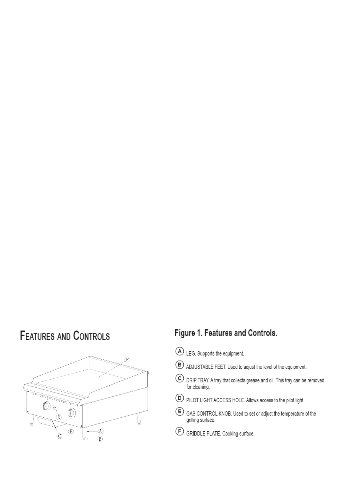
FEATURES AND CONTROLS:
Page 4

Gas Griddle 16”
1
30,000
Natural or LPG
Gas Griddle 24”
2
60,000
Natural or LPG
Gas Griddle 36”
3
90,000
Natural or LPG
Gas Griddle 48”
4
120,000
Natural or LPG
OPERATION:
Before initial use, turn the gas control knob to the maximum setting and allow the equipment to burn-in for 15 minutes.
Seeing smoke coming f r om the cooking surface i s normal during burn-in. After 15 minutes of burn-in, equipment is rea dy
for use.
1. Hold the leg and rotate the adjustable feet so the equipment is level.
2. Check the drip tra y frequentl y.
3. To ignite the burners, depre s s and turn the gas control knob to hig h position
4. Allow the equipment to pre-heat before attempting to use.
5. Adjust the valve set -point to obtain the desired level of heat.
CLEANING:
To maintain the appearance and increase the service life, clean your equipment daily.
DO NOT clean equipment with steel wool.
1. Allow the equipment to cool completely before cleaning.
2. Using a wire brush, scrape the griddle plate to remove any food residue.
3. To clean equipment, use either a damp cloth, sponge with soapy water or a metal scraper.
4. Empty and clean the drip tray.
MAINTENANCE:
• A qualified service company should check the unit for safe and efficient operation on an annual basis.
• Gas piping shall be a certain si z e a nd installed to provide a supply of gas sufficient to meet the full gas input o f the
equipment.
• A manual shut off valve should be installed upstream from the mani fold within 4 ft. (1.2m) of the equipment and in a
position whe re it can be reached in the event o f an emergency.
• Check entire gas piping system for leaks every so often. Using a gas leak detector or soapy water solution is recommended.
• Install equipment under efficient exhaust hood with flameproof filters with a distance of no less than 4 feet between the top
of the equipment and the filter s or any other combustible materia ls.
SPECIFICATIONS:
Description Burners BTU/hr Gas Type
Page 5

Page 6

Standard Series Griddle Parts List
Ref. No. Description QTY
1
Griddle plate
2 oil guide tube 1
3 front decorate plate 1
4 fixation plate for pilot 2
5 side boarding plate 1
6 rear boarding plate 1
7 plate to strengthen foot 2
8 set plate for boarding plate 1
9 side boarding plate 1
10 rear fixation plate for burner 1
11 rear plate 1
12 rear set plate for oil pan 1
13 pilot 2
14 gas pipe 2
15 burner support 2
16 burner assy 2
17 orifice 2
18 inlet gas pipe 1
19 inner chamber side plate, right 1
20 side plate, right 1
21 nut 4
22 gas valve 2
23 bolt 2
24 pilot valve 2
25 oil pan 1
26 front heat insulation plate 1
27 slideway for crumb tray 2
28 front panel 1
29 knob 2
30 set plate for inlet gas pipe 2
31 knob insert 2
32 foot 4
33 side plate, left 1
34 inner chamber side plate, left 1
1
Page 7

WARRANTY
Warrants to the original user of its gas equipment and related equipment that
said appliances and related equipment will be free from defects in material
and workmanship under normal use for a period of one (1) year from the date
of installation, with appropriate documentation. Should your equipment fail
within this time, upon approval, parts and labor charges will be covered by this
warranty.
WARRANTY
REGISTRATION
CARD
MAIL CARD
IMMEDIATELY
This card must be
mailed immediately
after installation date
for warranty to be in
effect.
National Service America • 230 Park Ave, Suite 1000 • New York, NY • 10169
(Name of Business)
(Address) (City) (State) (Zip Code)
(Model Number) (Serial Number)
This is to inform that I, __________________________________________________________
(Please print name of individual who owns business)
have had the above installed in my place of business _____________________
(Contact Phone Number) (Contact E-mail) (Signature of indiviudal who owns Business)
The above warranties are in effect from this installation date, or 90 days, which ever comes fi rst.
(Dealer Purchased From)
(Date of Purchase)
 Loading...