

Page 1
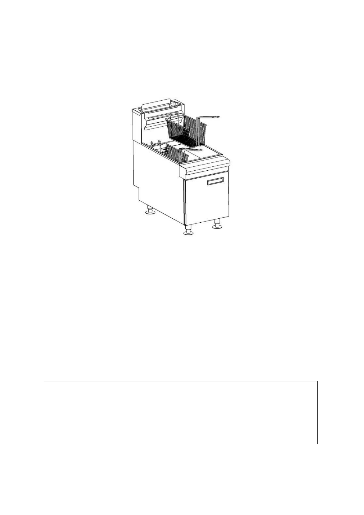
Gas Countertop Fryer
35-40 lb Model
45-50 lb Model
NG and LPG Models
This manual contains impor t a nt i nfor m a t ion regarding your
unit. Please read this manual thoroughly prior to
equipment set-up, operati on a nd m ai nt e na nce . Failure to comply
with regular maintenance guidelines outl ined in this manual may
void the warranty. MUST READ!!!
Page 2

WARNINGS
• Do not touch any hot surfa ces
• Do not immerse unit in liquid at any time
• Do not operate unattended
• Do not use thi s unit for anything other than intend ed use
• Do not use outdoors
• Always use on a firm, dry and level surface at least 12” from walls or any other obstruction
• Keep children and animals away from unit
• Any incorrect installation, alt erations, adjustments and/or improper maintenance can lead to property loss and injury.
All repairs should be done by authorized professionals only
• If gas odor is detected, shut unit down at main shutoff valve and contact service company
• Do not store or use gasoline or other flammable vapors or liquids in the vicinity of this or any applia nce
TO INSTALL
Before installing the fryer, verify what type of gas (natural or propane) agrees with the specifications on the fryer date plate, which
is located on the inside of the door panel. Make sure the fryer is configured for the proper elevation.
Record the fryer model, device and serial numbers for future reference in the space provided below. This information can be
found on the fryer data plate:
Fryer Model No: __________________________
Device: __________________________________
Serial No: ________________________________
Minimum clearance from c ombustible construction:
- 6” (15 cm) from the side of the fryer
- 6” (15 cm) from the back of the fryer
- The fryer may be installed on combustible floors
- Counter top must be constructed of a non-combustible material for installation.
Minimum clearance from noncombustible construction:
- 6’ from side of fryer
- 6 from back of fryer
Between the fryer and any open-top flame units:
- 16” (41 cm)
• Install fryer in an area with sufficient air supply for gas combustion at fryer burners.
• Do not obstruct the flow of combu stio n and ventilation air.
• Provide adequate clearance for air openings into the combustion chamber.
• Do not permit fans to blow directly onto fryer.
• Avoid wall-type fans, which create cross-currents within a room.
• Avoid open windows next to sides or back.
CODES AND STANDARDS
The fryer must be installed in accordance with:
In the United States:
- State and local codes, or in the absence of local codes, with:
National Fuel Gas Code, ANSI-Z223.1/NFPA #54 (latest edition). Copies may be obtained from The American Gas
Association Accredited Standards Committee Z223, @ 400 N. Capital St. NW, Washington, DC 20001 or the Secretary
Standards Council, NFPA, 1 Batterymarch Park Quincy, MA 02169-7471.
NFPA Standard #96 Vapor Removal from Cooking Equipment, latest edition, available from the National Fire Protection
Associatio n, Ba tter ymarch P ark, Q uinc y, MA. In the commonwealth of Massachusetts all gas appliances vented through
a ventilatio n ho od or exhaust s yste m wit h a damper or with a power means of exhaust shall comply with 248 CMR.
In Canada:
- Local codes
CAN/CSA-B149.1 Natural Gas I nstallation (latest edition).
CAN/CSA-B149.2 Propane Installation Code (latest edition), available from the Canadian Gas Association 178 Rexdale
Blvd., Etobicoke, Ontario Canada M9W 1R3.
The installer of this unit sho uld be awa re of state, county or local c ode fo r connect ing this eq uipment to det ermine
if an external regulator is required.
Page 3

TO ASSEMBLE
The fryer must be restrained to prevent tipping and the splashing of hot liquid. The means of restra int ma y be t he man ner
of installation, such as connection to a battery of appliances, installing the fryer in an alcove, or by separate means such as
adequate ties.
Note: The gas supply pressure at gas inlet should be less than 3.5 kPa.
1. Turn all burner control s OFF.
• Turn gas sup ply valve OFF .
2. Reconfigure Pressure Regulator
• Remove converter cap and pin from pressure regulator.
• Carefully remove pin from cap.
• Invert pin and reinstall in cap.
• Be sure gasket is in place on cap, then securely reinstall cap and pin on pre s sure regula t or.
3. Remove burners.
4. Remove and discard orifice hoods from burner control nozzles; install orifice hood s from kit.
5. Reinstall burners.
6. Turn gas sup ply valve ON .
7. Adjust pilot flames.
8. Adjust burner flames.
9. Affix propane conversion label to rear of appliance, near the nameplate.
Procedure is complete.
TO CONNECT FLUE
• Comply with Vapor Removal from Cooking Equipment, ANSI-NFPA Standard #96 (latest edition), available
from the National Fire Protection Association, Batterymarch Park, Quincy, MA 02269.
• Locate the fryer under a hood with adequate connection to an exhaust duct. The hood must extend 6” (15 cm)
beyond fryer on both sides.
• Clearance above the fryer should be adequate for combustion byproducts to be removed efficiently.
• An 18” (46 cm) minimum clearance should be maintained between the flue vent and the filters of the hood
venting system.
• Never make flue connections directly to the fryer.
• Do not obstruct the flow of the gases from the appliance. Proper air balance should be maintained in the room.
TO CONNECT GAS
• All gas supply connections and any pipe joint compound must be resistant to the action of propane gases
• The gas inlet is located on the lower rear of the fryer. Codes require that a gas s hutoff valve be installed in the
gas line ahead of the fryer.
• The gas supply line must be at least the equivale nt of ½” X (12.7 mm) iron pipe for si ngle units and 1-1/4”
(31.75 mm) for batteries. If using the optional quick-disconnect flex hose, ¾” X (19mm) iron pipe for single
units and 1 -1/4” (31.75 cm) iron pipe for batteries.
• Make sure the pipes are clean and free of obstructions, dirt, and piping compound.
• A battery requires one or two connections of appropriate size for the gas requirement.
Note: Prior to lighting, check all joints in the gas supply line for leaks. Use soap and water solution. Do not use an
open flame.
After piping has been checked for leaks, fully purge gas pipes to remove air.
GAS PRESSURES (ALL MODELS):
The gas pressure should be set at 4” W.C. (Water Column) (1.25 kPa) of pressure for nat ural gas and 10” W.C. (2.54kPa)
of pressure for propane gas. If incoming pressure exceeds ½ PSI (3.5 kPa), an additional pressure regulator must be
installed.
TESTING THE GAS SUPPLY PIPING SYSTEM:
When test pressures exceed ½ PSI (3.5 kPa), the fryer and its individual shuto ff val ve mus t be disconnected from the ga s
supply pipi ng system. When test pressures are ½ PSI (3.5 kPa) or less, the fryer must be isolated from the gas supply
piping system by closing its individual shutoff valve.
TO LEVEL
• Check the level of the fryer by placing a level on top of the fryer after gas connections have been made.
• Ensure that the fryer is level front-to-back and side-to-side in the final installed position.
Page 4

TO USE
Before any food preparation, thoroughly wipe protective oil from all surface parts and the tank interior with hot soapy
water to remove any film residue and dust or debris.
To Fill Tank with Shortening:
- Solid shortening should NOT be used with fryers.
- Melting solid shortening will damage the tank and void your warranty.
1. Close the drain valve.
2. Fill the fryer tank with liquid shortening.
3. Shortenin g level should be betwee n t he min and ma x lines in the fryer tank.
4. Shortening will expand when heated. Do not ill the fryer tank past the
5. MAX line.
6. Add fresh shortening as needed to maintain oil level.
Lighting the Pilot:
1. Open the door.
2. Turn the thermostat OFF. The thermostat is located behind the door.
3. Push the gas control val ve knob and turn to OFF. Wait 5 minutes for unburned gas to ve nt .
4. Push and turn gas control valve knob to the “L” in PILOT .
5. While still holding the knob in, light t he p ilot with a lit flame. Continue to depre ss the knob until pilot remains lit
when knob is released. If the pilot does not remain lit, repeat step 3 through 5.
6. Depress and turn gas control knob to ON.
7. If gas supply is interrupted, repeat steps 2 through 6.
Turning Fryer On:
1. Set the temperature knob to desired temperature.
2. After the set temperature has been reached, the thermostat shuts off the gas flow to burners.
3. The pilot remains lit. The b urners will cycle on and off, maintaining the set temperature.
*If the shortening becomes overheated, a high-temperature shutoff device will turn the ga s valve off and extinguish
the pilot. If the fryer shuts down du e to o verheating, DO NOT relight the pilot until the shortening te mperature is
below 300 F (149 C). If an overheating situation persists, contact your local authorized service office.
Turning Fryer Off:
1. Turn the thermostat OFF.
2. To keep the pilot lit, turn the gas valve to “L” in Pilot.
3. To shut off all gas to the system, including the pil ot, turn the gas valve knob to OFF.
Extended Shutdown
1. Turn the thermostat knob to OFF.
2. Push in the pilot knob and turn to OFF.
3. Thoroughly drain the fryer. Refer to DRAINING THE FRYER.
4. Clean the fryer according to CLEANING.
5. Turn off the main gas shut off valve.
BASIC USAGE
1. Set the desired temperature and allow shortening to heat.
2. To ensure equally fried items, make sure food pieces are about the same size.
3. Drain or wipe dry raw or wet foods to minimize splatter when lowering into hot shortening.
4. Add fresh shortening as needed.
Guidelines for Fry Baskets
• Do not overfill baskets. (See recommended basket capacities below)
• Carefully lower basket into oil.
• When frying doughnuts and fritters, turn pro duct only once during frying.
• When cooking French fries or onion rings, shake the basket several times carefully, as not to splatter oil.
• Batter-covered foods should be dropped carefully, one by one, into shortening or basket.
• If using the b a sket, first dip the basket into the shortening to reduce batter-build up on basket surfaces.
• When frying is completed, remove basket or product.
• Hang basket on rear hanger.
Fry Basket Capacity:
Recommended pounds per basket are 1.5 lbs. (0.7 kg).
Extending Shortening Life
Shortenin g life can be ext ended b y the following guidelines :
Page 5

• Do not salt foods over the fryer.
• Use good-quality shortenin g.
• Filter shortening daily (at a minimum).
• Replace shortening if it becomes poorly flavored.
• Keep equipment and surrounding area clean.
• Set thermostat correctly.
• Remove excess moisture and particles from food products before placing on fryer.
Draining the Tank
• Turn the thermostat to OFF.
• To keep the pilot lit, turn the gas valve to PILOT.
• Direct the drain spout into the container that you wa nt to drain the shortening into.
• Open the drain valve. The oil will drain in to the container. When the container is full or the fryer tank is
empty, close the drain valve. Repeat this step until the fryer is empty.
• If desired, perform the weekly clean-out as described under CLEANING.
• Once tank is completely empty, add new shortening and set thermostat to desired temperature.
Daily Filtering
• Filter shortening at least once a day. Refer to the instructions pro vid e d with your filtering equipment.
• A cold fryer will not drain properly.
• Always filter shortening between 250F and 350F.
• The shortening in the cold zone area will remain hard if the heat is only on for a few minutes.
• If necessary, use the clean-out rod to carefully stir the hard shortening to an area above the cold zone where
it will melt.
• Use the tank brush to help clear sides and tubes of debris.
CLEANING - NOTE: To maintain cleanliness and increase service life, the fryer should be cleaned daily. Do not
immerse in water or any other liquid. Hot oil and hot parts can cause burns. Use care when operating, cleaning, and
servicing t he fryer.
1. Clean the unit with the tank brush and a damp cloth then polish wit h a soft dry cloth.
2. Clean all exterior surfaces with warm soapy water.
3. To avoid fingerprints on highly polished surfaces of stainless steel, apply a cleaner that will leave a thin oily or waxy
film.
4. To avoid damage, do not use abrasive cleaners or metallic scouring pads.
5. Use a self-soaping, non-metallic scouring pad for stubborn discolorations.
6. If soap or chemical cleaners are used, be sure they are completely rinsed away with clear water immediately after
cleaning. Chemical residue could damage or corrode the surfaces of the unit.
Boil Out
Procedure should be done weekly or as required.
• Drain the tank as described under DRAINING THE TANK.
• Once the shortening has been drained, flush out scraps and sediment with a small amount of warm
shortening, using tank brush. Allow the tank to drain thoroughly.
• Close the drain valve and fill tank with non-corrosive, grease-dissolving commercial cleaner. Follow the
manufacturer’s instructions. Do not use chlorine or sulfate/sulfide cleaners.
• Add commercial boil-out solution. Solution level must be between the MIN and MAX levels on the fr yer
tank.
• Set thermostat to the temperature recommended for the solution being used . Allow solution to simmer for
about 15 to 20 minutes.
• Drain the cleaning solution from the t ank.
• Close the drain valve and refill the tank with wate r. Add 1 cup (1/4 L) of vinegar to neutr alize alkaline left
by the cleaner. Solution level must be between the MIN and MAX level on the fryer tank.
• Bring the solution to a simmer onl y, turn the thermostat off. Allow to stand for a few minutes.
• Drain the tank according to DRAINING THE TANK. Rinse thoroughly with clear, hot water. All traces of
cleaner must be removed. Dry the tank thoroughly.
• Close the drain valve and add shortening. Follow the FILLING TANK WITH SHORTENING procedure in
this manual . The fryer is now ready fo r use.
MAINTENANCE
- Hot oil and hot parts can cause burns.
- Use care when operating, cleaning, and servicing the fryer.
- Spilling hot fryer compound can cause severe burns.
- Do not move fryer without draining all frying compound from the tank.
- The fryer should be restrained to prevent tipping when installed in order to avoid the splashing of hot liquid.
Page 6

- The means of restraint may be the manner of installation, such as connection to a battery of appliances or
Model
Dimensions (mm)
35-40 lb model
27.5”x14.75”x31” (700*375*784)
45-50 lb model
30.25”x14.75”x31” (767*375*784)
Model
Number of
Orifice (mm)
BTU/hr.
Width Inch (cm)
Shortening lbs.
35-40 lb - NG
3
#45 (2.083)
60,000
14.9” (37.5)
35-40(16-18kg)
3
#54 (1.397)
60,000
14.9” (37.5)
35-40(16-18kg)
45-50 lb - NG
3
#41 (2.44)
75,000
14.9“ (37.5)
45-50(21-23kg)
3
#53 (1.51)
75,000
14.9” (37.5)
45-50(21-23kg)
Problem
Cause
Thermostat dial not turned on.
Thermopile (call service)
Thermostat dial not set to desire d temperature.
Temperature probe (call service)
Shortening too cold.
Drain pipe clogged with debris.
installing the fryer in an alcove, or by separate means, such as adequate ties.
FLUE VENT INSPECTION
- When the fryer is cool, inspect annually. Check the flue and clear any obstructions.
Service in the US and Canada
Contact your local Service office or address in the back of this manual.
DIMENSIONS
SPECIFICATIONS
35-40 lb - LPG
45-50 lb - LPG
TROUBLESHOOTING
Burner Tubes
No heat
(kg)
Pilot not lit.
Gas supply not turned on.
Wire connections loose (call service)
Wires connections need cleaning (call service)
Insufficient or too much heat
Tank will not drain
High limit tripped (call service )
Page 7

Page 8

Parts List for Gas Countertop Fryers
1 Left side plate 1
2 Rear bottom beam 1
3 tank assembly 1
6 basket hanging plate 1
7 Rear boarding plate 1
8 screw 2
9 fry basket 2
12 top plate of electric box 1
13 thermostat 1
14 temperature limiter 1
15 knob for thermostat 1
16 magnet 1
18 thermapile 1
19 1
20 pilot bracket 1
21 fix bushing of door shaft 1
22 front top beam 1
25 handle 1
26 outer plate of door 1
27 inner plate of door 1
28 bracket of extension pipe 1
31 clip to connect pilot bracket 1
32 plate to fix foot 4
33 Tension bar 1
34 Adjustable foot 4
37 1/4 Elbow 1
38 union 1
39 inner joint 2
40 extension gas pipe 1
41 gas valve 1
43 gas distibution pipe 1
44 1/2 elbow 2
45 union 1
46 test plug screw 1
47 injector pipe 3
50 burner 3
51 gas valve knob 1
52 scale plate 1
53 Holder 1
Reference
Number
Description
4 plate to fix gas distribution pipe 1
5 Rear plate 1
10 Tube screen Grate 1
11 right side plate 1
17 boarding plate of electric box 1
23 oil drain extension pipe 1
24 Front decoration board 1
Qty
29 door shaft support clip 1
30 drain valve 1
35 Front bottom beam 1
36 bottom plate 1
42 gas distibution pipe nut 2
48 brass tip 3
49 inlet pipe 1
54 knob shaft 1
Page 9

WARRANTY
Warrants to the original user of its gas fryers and related equipment that said
appliances and related equipment will be free from defects in material and
workmanship under normal use for a period of one (1) year from the date
of installation, with appropriate documentation. Should your equipment fail
within this time, upon approval, parts and labor charges will be covered by this
warranty.
The Stainless steel fry tank has a fi ve (5) year limited tank warranty. If during
the fi rst year only, the tank is found to have a leak and is verifi ed by an
authorized service company, the entire fryer will be replaced. After the fi rst
year a replacement tank will be sent free of charge excluding freight and labor
charges.
WARRANTY
REGISTRATION
CARD
MAIL CARD
IMMEDIATELY
This card must be
mailed immediately
after installation date
for warranty to be in
effect.
National Service America • 230 Park Ave, Suite 1000 • New York, NY • 10169
(Name of Business)
(Address) (City) (State) (Zip Code)
(Model Number) (Serial Number)
This is to inform that I, __________________________________________________________
(Please print name of individual who owns business)
have had the above installed in my place of business _____________________
(Contact Phone Number) (Contact E-mail) (Signature of indiviudal who owns Business)
(Dealer Purchased From)
(Date of Purchase)
The above warranties are in effect from this installation date, or 90 days, which ever comes fi rst.
 Loading...