

Page 1

Base Station
Telemetry Gateway A850
User Guide
valid for A850 firmware release 1.0
SMART WIRELESS SOLUTIONS
Page 2

ADC NO
TELEMETRY
ADCON TELEMETRY GMBH
INKUSTRASSE 24
A-3400 KLOSTERNEUBURG
AUSTRIA
TEL: +43 | 2243 | 38280-0
FAX: +43 | 2243 | 38280-6
http://www.adcon.athttp://www.adcon.at
ADCON INTERNATIONAL INC
2050 LYNDELL TERRACE
SUITE 120
CA-95616 DAVIS, USA
TEL: +1 | 530 | 753-1458
FAX: +1 | 530 | 753-1054
http://www.adcon.athttp://www.adcon.at
ADCON AUSTRALIA PTY. LTD.
ENFIELD PLAZA SA 5058
PO BOX 605
ADELAIDE AUSTRALIA
TEL: +61 | 8 | 8260-4682
FAX: +61 | 8 | 8260-4685
http://www.adcon.athttp://www.adcon.at
Proprietary Notice:
The Adcon logo, the A72x, A73x and A74x series, addIT™, addWAVE™, the A840 and A850
Telemetry Gateway, addVANTAGE®, and addVANTAGE Lite are trademarks or registered trademarks of Adcon Telemetry. All other registered names used throughout this publication are
trademarks of their respective owners.
Neither the whole nor any part of the information contained in this publication may be reproduced in any material form except with the prior written permission of Adcon Telemetry.
This publication is intended only to assist the reader in the use of the product. Adcon Telemetry
shall not be liable for any loss or damage arising from the use of any information in this publication, or any error or omission in such information, or any incorrect use of the product.
Document Release: 1.2, September 2007
Copyright ©2001—2007 by Adcon Telemetry GmbH.
All rights reserved.
Page 3

Chapter 1. Introduction ________________________________________________ 13
Scope ________________________________________________________________ 13
Conventions ___________________________________________________________ 14
What is the A850 Telemetry Gateway? ____________________________________ 15
Adcon's Telemetry Network _____________________________________________ 18
What's new on the A850 ?_______________________________________________ 20
Chapter 2. System Setup _______________________________________________ 23
Package Contents ______________________________________________________ 23
Elements on A850 ______________________________________________________ 24
LED Indicator _______________________________________________________ 24
LEDs and LED patterns ____________________________________________ 24
Connectors _________________________________________________________ 25
Mains:___________________________________________________________ 25
Radio Modem (connection to A440): ________________________________ 25
Modem: _________________________________________________________ 26
Console:_________________________________________________________ 26
USB: ____________________________________________________________ 26
LAN: ____________________________________________________________ 26
Reset Button _____________________________________________________ 26
Installation ____________________________________________________________ 26
Installing the outdoor unit ____________________________________________ 29
Installing the indoor unit______________________________________________ 31
Initialize the base station _____________________________________________ 32
License of the Gateway ______________________________________________ 32
Connecting to the GUI _______________________________________________ 33
Starting of the Web Browser _______________________________________ 33
Login Procedure__________________________________________________ 38
CHAPTER
3
Page 4

CHAPTER
4
Principles of GUI operation ______________________________________________ 40
The main window ____________________________________________________ 40
Commands on the Menu Bar __________________________________________ 41
File Commands ___________________________________________________ 41
FileLogin ______________________________________________________ 41
FileLook and feel _______________________________________________ 42
FileExit ________________________________________________________ 43
EditUndo ______________________________________________________ 43
EditRedo ______________________________________________________ 44
Configuration Commands__________________________________________ 44
ConfigurationRefresh ____________________________________________ 44
ConfigurationLock Lock Gateway ________________________________ 45
ConfigurationLock Show Lock ___________________________________ 46
ConfigurationLock Unlock ______________________________________ 46
ConfigurationUpdate ____________________________________________ 47
ConfigurationRestore ____________________________________________ 49
ConfigurationLoad ______________________________________________ 51
Tools Commands _________________________________________________ 53
To ol s LicenseShow License _____________________________________ 53
To ol s LicenseSet License _______________________________________ 54
To ol s JobStart Job_____________________________________________ 54
To ol s JobStop Job ____________________________________________ 56
To ol s Time Configuration _________________________________________ 57
To ol s CommunicationDirect Commands__________________________ 58
To ol s CommunicationBroadcast _________________________________ 62
To ol s Save System State__________________________________________ 65
To ol s Search ____________________________________________________ 67
To ol s Settings ___________________________________________________ 69
Commands on Tool Bar_______________________________________________ 71
Backup __________________________________________________________ 72
Restore __________________________________________________________ 72
Load ____________________________________________________________ 72
Save_____________________________________________________________ 72
Undo ____________________________________________________________ 72
Search ___________________________________________________________ 72
Main Window views __________________________________________________ 73
Tree view ________________________________________________________ 73
Page 5

Table view _______________________________________________________ 74
Popup Context Menu ________________________________________________ 75
Detail window_______________________________________________________ 77
Web Interface__________________________________________________________ 78
Home ______________________________________________________________ 78
Credits and Licenses _________________________________________________ 80
GPL________________________________________________________________ 80
LGPL_______________________________________________________________ 81
ASL ________________________________________________________________ 82
Tools_______________________________________________________________ 83
Debugging tools _________________________________________________ 85
Configuration tools _______________________________________________ 85
Firmware tools ___________________________________________________ 86
CHAPTER
5
Page 6

CHAPTER
6
Chapter 3. Configuring the Gateway ____________________________________ 87
PPP Dialup __________________________________________________________ 89
Job scheduling ___________________________________________________ 93
Job status________________________________________________________ 95
Job dependent settings ___________________________________________ 95
Primary Account __________________________________________________ 96
Secondary Account _______________________________________________ 97
Dynamic DNS _______________________________________________________ 98
Job scheduling __________________________________________________ 101
Job status_______________________________________________________ 103
Job dependent settings __________________________________________ 103
Primary Server ___________________________________________________ 104
Secondary Server ________________________________________________ 105
SSH Tunnel ________________________________________________________ 105
Job scheduling __________________________________________________ 108
Job status_______________________________________________________ 110
Job dependent settings __________________________________________ 110
Primary Server ___________________________________________________ 111
Secondary Server ________________________________________________ 112
Notification Sending ________________________________________________ 112
Job scheduling __________________________________________________ 115
Job status_______________________________________________________ 117
Primary Server ___________________________________________________ 117
Secondary Server ________________________________________________ 119
NTP_______________________________________________________________ 119
Job scheduling __________________________________________________ 122
Job status_______________________________________________________ 124
Job dependent settings __________________________________________ 124
Primary Server ___________________________________________________ 125
Secondary Server ________________________________________________ 125
Dialup Modem _____________________________________________________ 126
Dialup Parameter ________________________________________________ 130
Dialup status ____________________________________________________ 132
Job dependent settings __________________________________________ 132
________________________________________________________________ 132
PPP parameter___________________________________________________ 132
Wireless Modems___________________________________________________ 133
Page 7

Device parameter________________________________________________ 137
Modem status___________________________________________________ 138
Radio parameter_________________________________________________ 139
Modem-Type dependent settings__________________________________ 140
GPRS Modems _____________________________________________________ 141
Configuration ___________________________________________________ 144
State ___________________________________________________________ 144
Users _____________________________________________________________ 145
Configuration ___________________________________________________ 148
State ___________________________________________________________ 149
Operating System __________________________________________________ 150
Flush interval____________________________________________________ 152
Notifications ____________________________________________________ 152
Last times events ________________________________________________ 153
Networking ________________________________________________________ 153
Ethernet Settings ________________________________________________ 156
Console Settings ________________________________________________ 157
DHCP Settings __________________________________________________ 158
Primary DNS Server ______________________________________________ 158
Secondary DNS Server ___________________________________________ 159
Gateway Detail_____________________________________________________ 159
Configuration ___________________________________________________ 162
State ___________________________________________________________ 163
CHAPTER
7
Chapter 4. Using the Gateway _________________________________________ 165
Sensor Connections ___________________________________________________ 165
Analog Input_______________________________________________________ 168
Pulse Counter______________________________________________________ 168
Digital I/O _________________________________________________________ 168
Internal Input ______________________________________________________ 168
Logical Channels and Output Channels _______________________________ 169
SDI-12 Bus ________________________________________________________ 169
Actuator Connections _______________________________________________ 170
Page 8

CHAPTER
8
Sensor Type Configuration ______________________________________________ 170
Adding Custom Sensors _____________________________________________ 170
Sensor Tables ______________________________________________________ 171
Sensor Types _______________________________________________________ 174
Analog sensor types ________________________________________________ 176
Common settings ________________________________________________ 178
Analog sensor settings ___________________________________________ 179
Analog sensor sampling methods __________________________________ 180
Conversion settings ______________________________________________ 181
Counter sensor types________________________________________________ 182
Common settings ________________________________________________ 184
Conversion settings ______________________________________________ 185
Digital sensor types _________________________________________________ 186
Common settings ________________________________________________ 188
Digital sensor settings ____________________________________________ 189
Conversion settings ______________________________________________ 190
Internal sensor types ________________________________________________ 191
Common settings ________________________________________________ 192
Internal sensor settings ___________________________________________ 193
Conversion settings ______________________________________________ 194
LC sensor types ____________________________________________________ 195
Common settings ________________________________________________ 197
Sensor settings __________________________________________________ 198
Conversion settings ______________________________________________ 198
OC sensor types ____________________________________________________ 199
Common settings ________________________________________________ 201
Output settings __________________________________________________ 202
Conversion settings ______________________________________________ 202
SDI sensor types ____________________________________________________ 203
Common settings ________________________________________________ 205
SDI sensor settings _______________________________________________ 206
Conversion settings ______________________________________________ 206
Combo Sensor Types________________________________________________ 207
Sensor types ____________________________________________________ 210
Page 9

Logs _________________________________________________________________ 211
Call Journal________________________________________________________ 212
Poll Journal ________________________________________________________ 213
System Log ________________________________________________________ 214
Log types_______________________________________________________ 215
Log types Buttons _______________________________________________ 216
System Log Windows ____________________________________________ 217
System log Buttons ______________________________________________ 217
CHAPTER
9
Page 10

CHAPTER
10
RTU Network Configuration _____________________________________________ 218
Definition of RTU Groups ____________________________________________ 218
Definition of RTUs __________________________________________________ 222
RTU Context Menu_______________________________________________ 222
RTU Configuration __________________________________________________ 225
RTU - Data ______________________________________________________ 226
RTU - State Information ___________________________________________ 232
RTU - Routing ___________________________________________________ 237
RTU Administration _________________________________________________ 241
Copy RTU_______________________________________________________ 242
Replace RTU ____________________________________________________ 244
Convert RTU ____________________________________________________ 246
Sensor Administration _______________________________________________ 249
Connect sensors _________________________________________________ 250
RTU Data Management______________________________________________ 256
Get data ________________________________________________________ 256
Set data ________________________________________________________ 259
Configure _______________________________________________________ 260
Refresh data_____________________________________________________ 262
Erase data ______________________________________________________ 263
RTU Status Management ____________________________________________ 263
Ping RTU________________________________________________________ 263
RTU Communication Management____________________________________ 265
Configure Poll/Ping ______________________________________________ 265
Change Frequencies _____________________________________________ 268
RTU Logs __________________________________________________________ 269
Call journal______________________________________________________ 269
Poll journal ______________________________________________________ 270
RTU Printing _______________________________________________________ 270
IO Port Configuration _______________________________________________ 271
IO Port Context Menu ____________________________________________ 271
Sensor Configuration ________________________________________________ 272
Sensor Context Menu ____________________________________________ 272
Sensor details ______________________________________________________ 274
Common details _________________________________________________ 275
Special sensor settings____________________________________________ 276
Calibration ______________________________________________________ 278
Page 11

Newest slot _____________________________________________________ 278
Requests _______________________________________________________ 279
Replace sensor _____________________________________________________ 280
Chapter 5. Console Commands ________________________________________ 283
Establishing Console Connection________________________________________ 284
Console Commands details_____________________________________________ 292
Console Login _____________________________________________________ 293
Upgrade the gateway _______________________________________________ 296
Configuration ______________________________________________________ 298
Configuration Quick setup ________________________________________ 298
Configuration Expert setup _______________________________________ 300
Backup the Gateway Configuration ________________________________ 302
Restore the gateway configuration _________________________________ 305
Erase the gateway configuration___________________________________ 307
Encryption_________________________________________________________ 308
HTTPD Encryption _______________________________________________ 308
SSHD Encryption ________________________________________________ 310
Show the Java archive key ________________________________________ 312
Set date and time __________________________________________________ 312
Licensing __________________________________________________________ 313
Debugging ________________________________________________________ 314
Callback PPP server _________________________________________________ 314
Who am I?_________________________________________________________ 315
Operating-system shell______________________________________________ 316
Exit _______________________________________________________________ 317
CHAPTER
11
Chapter 6. Appendix _________________________________________________ 319
Technical Data ________________________________________________________ 319
Glossary______________________________________________________________ 319
Free and Open-Source Software ________________________________________ 319
Page 12

CHAPTER
12
Third-party Software ___________________________________________________ 321
hermit 1.2 - ARM bootloader ______________________________________ 321
linux 2.4 - Operating system kernel_________________________________ 321
glibc 2.1.6 - GNU C Library________________________________________ 322
zlib - General purpose compression library __________________________ 322
expat - XML parser library _________________________________________ 322
libmodem - Modem handling library _______________________________ 322
md5 - Message digest algorithm ___________________________________ 323
ghttpd - GazTek HTTP daemon ____________________________________ 323
tinylogin - Login program _________________________________________ 323
snarf - HTTP download utility ______________________________________ 323
putsms - SMS sending utility_______________________________________ 324
ppp - Point-to-Point protocol daemon ______________________________ 324
ntpclient - Network Time Protocol client ____________________________ 324
mini_sendmail - send mails to an SMTP server _______________________ 325
busybox - UNIX commandline utilities ______________________________ 325
bash - command line interpreter ___________________________________ 325
cu - Taylor UUCP _________________________________________________ 326
isc-dhcpd - ISC DHCP daemon ____________________________________ 326
wu-ftpd - File transfer protocol daemon_____________________________ 327
gdbserver - server stub of the GNU debugger _______________________ 327
procps - The /proc file system utilites and library _____________________ 327
sash - Stand-alone shell ___________________________________________ 327
telnetd _________________________________________________________ 327
License texts __________________________________________________________ 328
WU-FTPD Software License __________________________________________ 328
GPL-v2 ____________________________________________________________ 330
LGPL-v2 ___________________________________________________________ 338
mini_sendmail ______________________________________________________ 350
glibc ______________________________________________________________ 351
Page 13

Chapter 1. Introduction
Scope
This manual describes the A850 Telemetry Gateway and its use as
a Base Station of an Adcon Telemetry Network. Aside of the proprietary Base Station configuration consisting in an A850 Telemetry Gateway combined with an A440 Wireless Modem (“Adcon
Wireless Telemetry Network”), also Base Station configurations
using different means of communications between the Gateway
and the other components of the Adcon Telemetry Network are
covered.
CHAPTER 1
Scope
13
Page 14

CHAPTER 1
14
Introduction
Conventions
The following conventions apply to this documentation:
Italics
Bold
fixed font
FileSave
Note
CAUTION
WAR NI NG
<value>
Indicates that the text formatted that way represents a
variable which must be substituted for something specific, in accordance with an appropriate explanation.
Otherwise, Italics can also be used just to emphasize
certain words or letters.
Indicates special emphasis of the text, but also menu
names and items in a window.
Indicates either system messages or characters you
must type in.
Indicates a menu selection. The example at hand
means that you have to select at first the
and then the
Indicates information of interest. Notes appear
the information they apply to.
Indicates that you may get unexpected results if you
don’t follow the instructions. Cautions appear
Save option.
File menu
after
before the information they apply to.
Indicates danger to yourself or damage to the device if
you don’t follow the instructions. Warnings appear
before the information they apply to.
Indicates a required input parameter.
[value]
Indicates an optional input parameter.
Page 15

What is the A850 Telemetry Gateway?
What is the A850 Telemetry Gateway?
The A850 Telemetry Gateway is a low-power, battery-backed
device that acts as an interface between an Adcon Telemetry Network and one or more hosts running addVANTAGE or similar data
acquisition software. The capabilities of the A850 allow to manage
up to 1000 Adcon RTUs (Remote Telemetry Units), depending on
the version used. In combination with Adcon's Transceiver Module
(Wireless Modem) A440, the A850 constitutes the Base Station of
an Adcon Wireless Telemetry Network.
The A850 Telemetry Gateway provides the following functions to
the user:
• Gateway: the A850 routes data, commands and events
between different physical networks (GSM, POTS, LAN,
Internet, Adcon Radio Network),
• Protocol converter: the A850 translates data and commands
between different protocols (Adcon RTU command line,
addUPI),
• Temporary storage: the A850 provides a short-term data
buffer for actual and historical data,
• Monitor and debugger: the A850 provides monitoring and
debugging capability for the Adcon Radio Network.
CHAPTER 1
15
The data of the RTUs will be automatically acquired, buffered and
forwarded through an Ethernet interface or a modem to one or
more PCs for analysis and further utilization.
Thereby, the remote data acquisition (polling) of RTUs can be
achieved through
• Wireless Modems A440,
• Telephone Modems,
• GSM Modems or
• TCP connections from GPRS Units.
Page 16

16
CHAPTER 1
Introduction
The forwarding of the data from the A850 to the data assessment
PC is achieved either through
• Ethernet or
• Telephone Modem.
For data communication from and to an A850, private (LAN, VPN)
or public means for data communications (e.g. the Internet) can be
used.
The Gateway is based on a powerful 32 bit ARM processor running
the Linux operating system. It has 256 MB Compact Flash acting as
a hard disk and 64 MB RAM.
The Compact Flash data storage device of the A850 with its capacity of 256 MB allows to buffer data sampled from 1000 stations for
14 days. The built-in rechargeable battery maintains the function of
the A850 also in case of temporary outages of the primary power
source for up to approximately 24 hours (the achievable time of
operation without mains power depends on the number of RTUs
the Gateway has to poll), preventing any data loss. The central unit
is prepared for future software updates and can be upgraded on
location. The communication with the Wireless Modem A440
mounted e.g. on a roof will be ensured by a serial RS-485 connection. This connection uses a cable which is by default 30 m long
and easy to lay. Upon request, special low-attenuation cables of up
to 90 m can be provided by Adcon.
The A440 Wireless Modem is a low-power, narrow-band data
transceiver operating in the 70 cm band. It implements Adcon's
low-speed radio protocol and is therefore compatible with all
Adcon RTUs. In addition, the A440 modem supports a high-speed
wireless protocol that will be used by future Adcon devices. The
A440 has an 8 bit Flash-based microcontroller and can also be
updated in the field. The A440 is delivered in an IP-65/67 enclosure.
Page 17

CHAPTER 1
What is the A850 Telemetry Gateway?
WARNING This manual is valid only for release 1.0 of the
Gateway's firmware. You can verify that you have the appropriate
firmware by logging onto the web page of the A850 via your
internet browser. The following should be displayed on the
bottom of the web page of the A850:
Release 1.0, © 2007 Adcon Telemetry GmbH
All trademarks mentioned here are registered with
their respective owners.
If firmware upgrades will become available in the future, you will
be able to download a new image file from Adcon's web site
(http://www.adcon.at) to your local PC or to get the new firmware
on a data storage device from Adcon's technical support. In any
case, as first step, you will have to make the new firmware
available in form of an image or on a data storage device on your
local PC and then to upgrade your A850 by transferring the new
firmware from your local PC to your A850 by either uploading the
software, proceeding as described in detail in chapter 2, “Web
Interface”, “Tools”, “Firmware Tools”, “Upload an A850 firmware
image stored as local file” or, alternatively, by downloading the
software from your PC to your A850 as described in chapter 5,
“Configuration”, “Upgrade your A850 Gateway".
17
However, as firmware upgrades may have various impacts on the
function of the upgraded device, we strongly recommend that you
first check on Adcon's web site or by contacting Adcon's technical
support which effects you would have to expect from an upgrade
before you perform it. Depending on the nature of an upgrade,
this documentation may remain valid or may require also changes.
Thus, Adcon cannot be held responsible for possible impacts of
firmware upgrades made without appropriate precautions and
accompanying measures.
Note: for USA: THIS DEVICE COMPLIES WITH PART 15 OF THE
FCC RULES. OPERATION IS SUBJECT TO THE CONDITION THAT THIS DEVICE DOES NOT CAUSE HARMFUL
INTERFERENCE.
Page 18
CHAPTER 1
18
Introduction
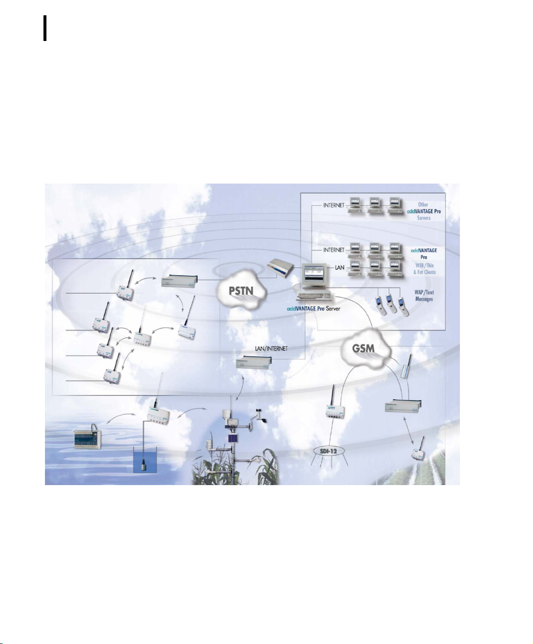
Adcon's Telemetry Network
The A850 represents the link between the various RTUs and the
PC(s) used for evaluating the sensor data and for transmitting control commands, respectively.
.
Figure 1. Schematics of a Remote Telemetry Network
To build a Remote Telemetry Network you need the following:
• one or more Remote Telemetry Units (RTUs) A720, A723,
A731, A732, A733, A733GSM or A740,
Page 19

CHAPTER 1
Adcon's Telemetry Network
• an A850 Base Station,
• data acquisition and control software, such as Adcon's
addVANTAGE Pro 5 software,
• appropriate means of communications to access your Remote
Telemetry Units, e.g. an Adcon Wireless Modem A440 or
other means of communications, depending on the types of
RTUs you are using. Specifically, if you use the A733GSM, you
either need a telephone line with external modem or an
external GSM modem such as the WorldCom M1206.
Note: For additional information about the RTUs and the addVAN-
TAGE software, consult the respective user manuals.
19
Page 20

CHAPTER 1
20
Introduction
What's new on the A850 ?
The A850 is the successor of the well proven A840 Gateway and
offers the following new features:
• USB device support : USB based devices are supported as
long as they conform to the USB standards for the storage or
communication device classes. The device types that can be
used are
• USB to RS-232 adapters or
• USB modems.
Note: A list of supported devices will be provided with the Firm-
ware release notes. Devices not listed may work, but Adcon
advises not to try as such attempts and possible damage
resulting from it would be at the user’s sole and own risk.
• Multiple modem support: The A850 support more than one
modem. For every modem, the user can configure
• a V110 mode whitelist which tells the A850 for which
phone number the digital V110 mode is supported (V110
mode is supported by most GSM and ISDN networks,
but not by POTS (analog) phone networks),
• whether the modem should answer incoming calls (and
after which number of rings).
Note: A list of supported modems will be provided with the firm-
ware release notes. Devices not listed may work, but Adcon
advises not to try as such attempts and possible damage
resulting from it would be at the user’s sole and own risk.
• Protocol support: The A850 supports encrypted network
protocols, namely
• SSH as replacement for TELNET,
• HTTPS as replacement for HTTP.
Note: The unencrypted protocols is still be supported, however it
is highly recommended not to use them when accessing the
A850 over public (insecure) networks (especially the internet).
Page 21

CHAPTER 1
What's new on the A850 ?
• Users and user permissions: The A850 support up to 100
users with different user permissions:
• one root user which may configure the A850 hardware,
• multiple administrator level users which may configure
the RTU network and give RTU access permissions to
ordinary users,
• multiple ordinary users which may query and configure
only RTUs and sensors for which they have access
permissions.
Note: As default, only the root user is configured.
• Dial-up networking and dynamic IP addresses: To support
A850 devices that do not have an official internet hostname
and IP address, the following features are supported:
• dialling an ISP on given schedule, as callback after
dialling in and/or when notifications must be delivered,
• updating dynamic DNS services, such as DynDNS (this
requires that the A850 gets an official IP address
accessible over the internet after connecting to an ISP. If
the A850 is installed in a private network behind a NAT
router, dynamic DNS is not guaranteed to work),
• hiding the A850 behind an SSH server that is accessible
from the internet (the A850 can be reached through the
SSH server's address).
21
Note: For each of these services, a secondary (backup) connection
may be configured which is used when the primary connection fails.
• RTU routing: The A850 support multiple alternative routes to
an ISM-based RTU. Switching between routes is done by
examining the usage period of the configured routes (if the
usage times of routes overlap, the route with the higher
prority is active).
• Polling:
• The A850 supports multiple polling priorities: all RTUs
with higher priority are served first, then all RTUs with
Page 22

22
CHAPTER 1
Introduction
lower priorities. The user is responsible for choosing
priorities and polling intervals properly (for example:
configuring a short polling interval and a high priority for
too many stations may result in RTUs of lower priority
never being polled).
• The A850 supports polling multiple RTUs in parallel if
they are reached using different modems or A440
interfaces.
• Statistics and monitoring: The A850 supports A850 and RTU
network statistics:
• load, memory and disk usage of the A850,
• average delay and average radio error rates for the RTUs.
• Sensors: The RF quality, the battery level and the internal
temperature of the RTU as well as the statistical data for
average RTU delay time and average RTU connection quality
may be considered as data from internal sensors of an RTU.
This means that the data representing these parameters can
be used by addVANTAGE like data from normal sensors.
• User interface: All interactions between the user and the A850
(configuration, monitoring, diagnostics, ...) are done by a
JAVA based Graphical User Interface (GUI).
Note: An A440 device connected to an A850 must have firmware
revision 3.0.0 or newer.
CAUTION The A850 do not support addVANTAGE 3.x software
and the A730MD RTU.
Page 23

Chapter 2. System Setup
Package Contents
Before proceeding to the installation of your Base Station, first verify that you have received all of the following components:
• the A850 Telemetry Gateway,
•a power cord,
• a serial null modem cable,
• a network cable (twisted-pair standard Ethernet cable),
• a CD with the manual,
• a CE conformity declaration.
CHAPTER 2
Package Contents
23
If any of the above items is missing, contact your dealer.
If you plan to use the Gateway's built-in modem (e.g. in conjunction with A733GSM/GPRS RTUs), you will also need a modem
cable suitable for your telephone jack (not included).
Page 24
CHAPTER 2
24
System Setup
Elements on A850
LED Indicator
LEDs and LED patterns
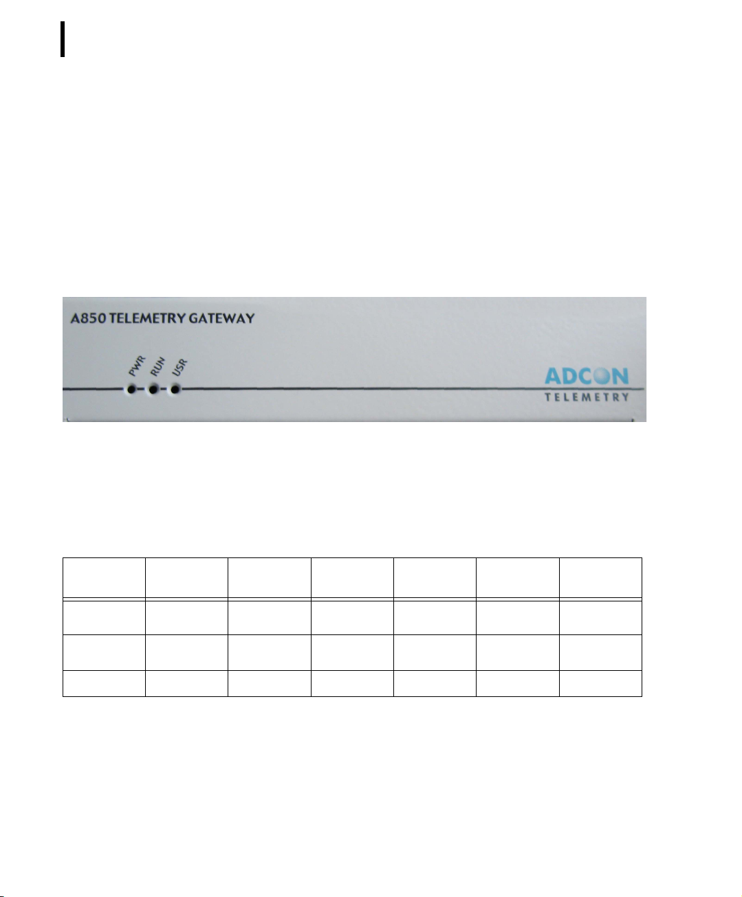
The device has three LEDs which are forced on during a CPU reset
and during the boot process.
Table 1. LED pattern
LED On
PWR
RUN
USR
AC present Battery > 75% Battery > 50% Battery > 25% Battery low -
Booting - - Error No
Kernel - - - RTU activity Sysinit
Figure 2. Front of the A850
Blinking
slow
Blinking
Blinking
fast
Flashing Off
-
configuration
All three LEDs are off if there is no power (neither AC nor battery).
Please notify that this LED pattern is never used while the system is
powered.
Page 25
CHAPTER 2
Elements on A850
All three LEDs are on while the device is in reset state or booting
the (Linux) operating system kernel.
The PWR and RUN LEDs are on and the USR LED is off while the
A850 is initialized (the CF card is checked, the configuration is
loaded and various services are started).
The activity LED flashes for 0.1 seconds if there is an RTU command sent or if the answer is received.
The “Error mode” LED pattern is used if there is a serious hardware error (unable to read CF card).
The “No configuration mode” LED pattern is used as factory
default (as long as there is no root password configured and no
basic network configuration given).
The “Battery low power” LED pattern is used while shutting down
the Gateway due to low battery.
25
Connectors
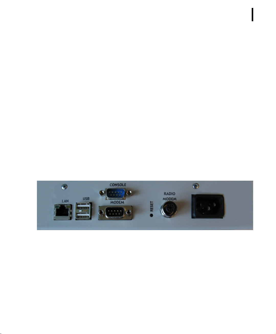
Figure 3. Back of A850
Mains:
AC Power Inlet (3 pin male connector for 90 - 240 V)
Radio Modem (connection to A440):
M 12 circular 4 pin female connector
Page 26

CHAPTER 2
26
System Setup
Modem:
9 pin male D-SUB connector
Console:
9 pin male D-SUB connector
USB:
2 USB slots (USB 2.0 supported)
LAN:
RJ-45 8 pin female connector
Installation
Reset Button
The reset button can be reached at the back of the Gateway (by
using a short piece of wire, a paperclip or a ballpoint pen).
Depending on the AC state the Gateway is reset (if AC is present)
or turned off (if no AC is present).
Note: since a reset destroys all configuration changes and mea-
surement data not yet stored in the FLASH, as well as the
system messages, the reset button should be only used as
an emergency measure (i.e. when there is no other way to
reboot the Gateway in a controlled way by using the CLI or
web interface).
Before proceeding with the installation, take a moment to plan
your network. First, in a Wireless (Radio) Network, it is essential to
realize the importance of selecting a good location for the transceiver and, as the admissible distance between the transceiver and
the Gateway is limited, for the complete Base Station. If the A850
Page 27

CHAPTER 2
Installation
is used in combination with one or several Adcon Wireless
Modem(s) A440, the Base Station configuration will consist in an
indoor unit (the A850) and one (or several) outdoor unit(s), the
A440(s). You must consider several factors, some of them quite
contradictory, when choosing the location:
• From a radio perspective, the height of the receiving antenna
is essential: the higher the antenna, the greater the range of
communication. For the GSM-operated RTUs, this is not an
issue, but you must make sure you have good on-site
coverage from your cellular provider.
• The Base Station should be situated in the same building
where the people managing the Base Station work, or at least
spend some of their time.
27
• Places like cellars, near heat sources, or damp locations are
not suitable.
• Geographically, it is better to have the Base Station in the
center of the area where the RTUs will be installed (this does
not apply to A733GSM stations).
• If you plan to use the Base Station as a server to allow other
people to log in and get data, be sure that a telephone line is
available exclusively for this use.
• Adcon also recommends that you have a telephone
connection next to the PC for when you need technical
support.
The communication distance you can achieve is directly proportional to the mounting height of the receiving antenna. The propagation of the radio waves used by the Adcon Wireless Modem
corresponds basically to the line of sight. Due to the curvature of
Page 28

CHAPTER 2
28
System Setup
the earth, on flat terrain, the maximum distance which can be
reached depends on the height above ground of the antennas of
the transceivers of the Base Station and of the measuring stations.
You can't do much on the remote station side, but you have more
options with the Base Station. Some typical examples of distances
achieved under various conditions are shown in Table 1.
The addIT RTU, however, uses low-power technology and was not
designed to communicate over large distances. The typical "lineof-sight" distance an addIT can communicate is 800 m (approximately half a mile). This is valid if the partner device is mounted on
a 3 m mast (9 ft) and the addIT is mounted on a 30 cm mast (1 ft).
The above figures are estimates based on a great deal of experience with installing this kind of equipment and assume a typical
height of 3 m (9 ft) for the antennas of the remote measuring stations. Similarly, ideal physical conditions are assumed for the terrain including a flat, open, non-urban environment.
Receiving antenna
height
6 m (18 ft) 5 km (3 miles)
10 m (31 ft) 8 km (5 miles)
20 m (62 ft) 16 km (10 miles)
30 m (92 ft) 24 km (15 miles)
Table 1. Communication between Base Station and RTUs A730MD/
A733/A740
Typical distances
achieved
What conclusions can be drawn from Table 1? Primarily, you can
see the importance of having the Base Station antenna as high as
possible. To gain antenna height, you have several options:
• Build a mast directly on the ground; however, a 30 m (100 ft)
mast may not be a practical option.
• Set up a mast on a tall building (of course, it has to be the
building where you want to have the Base Station).
• Install the Base Station in a building that is situated on a hill.
Page 29

Note: The cable for the outdoor unit delivered with the system is
by default 30 m (about 100 ft) long. If necessary, however,
you can increase the distance between your indoor and your
outdoor unit up to 90 m by using special low-attenuation
cables which can be provided upon request by Adcon.
To use the Telemetry Gateway and Wireless Modem, you need to
do the following:
• Install the outdoor unit.
• Install the indoor unit.
• Initialize the Base Station.
Installing the outdoor unit
Install the outdoor unit (transceiver, “A440 Wireless Modem") on
the rooftop of the house where the Base Station will be located or
on top of a nearby mast. The transceiver has two connectors: one
for a whip antenna (supplied with the A440) and a second that
accommodates the connection cable to the indoor unit.
CHAPTER 2
Installation
29
Note: The installation of the outdoor unit should be performed by
a certified electrician. Make sure that the mast on which the
A440 Wireless Modem will be installed is properly
grounded. Local laws or other regulations may apply.
Page 30
CHAPTER 2
30
System Setup
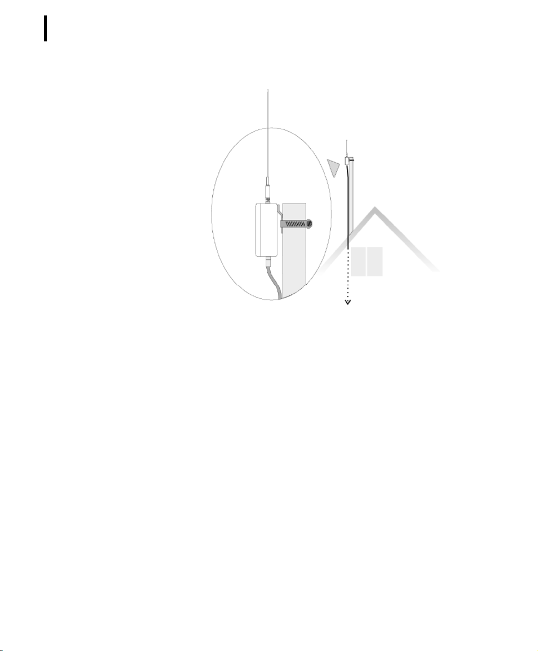
Figure 4. Outdoor Unit Installation
Complete the following steps to install the outdoor unit:
1. Fasten the Wireless Modem to the aluminum mast (provided
by Adcon) using the supplied ring clamp.
2. Fasten the antenna to the Wireless Modem.
3. Plug the proper end of the communication cable into the
lower connector of the Wireless Modem.
4. Secure the mast in its place on the roof.
5. Run the cable to the indoor unit.
Note: The cable supplied to connect the outdoor unit to the A850
Telemetry Gateway is 30 m long and cannot be extended,
but special low-attenuation cables with a total length of up
to 90 m can be provided upon request by Adcon.
In addition, if you are upgrading an existing A730SD installation,
you can use the low attenuation coaxial cable provided with the
A730SD’s high gain roof antenna.
Page 31
WARNING We highly recommend to only use the low attenuation
RS-485 cables provided by Adcon with a total length of up to 90 m
because attempts to make extensions using other cables could
make your Wireless Modem inoperable, due to the voltage loss on
the additional cable length. Also, damage to the Modem could
result from inappropriate cable impedance.
Installing the indoor unit
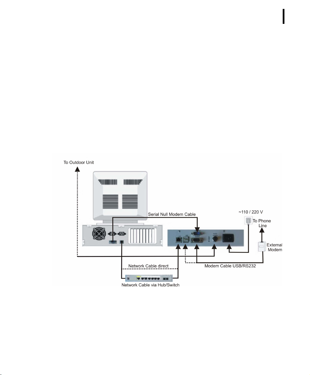
The indoor unit is the Telemetry Gateway A850. Connect the
cables to the Gateway as shown in Figure 5.
CHAPTER 2
Installation
31
Figure 5. Indoor Unit Installation
If you are using a hub or switch to connect several computers in a
local area network (LAN), use the twisted-pair Ethernet cable that
Adcon provides to connect the Gateway to the hub. If your computer is a standalone PC and is not part of a LAN, you can connect
it directly to the Gateway, as shown in Figure 5, but you will need
Page 32

CHAPTER 2
32
System Setup
Initialize the Base Station
to provide your own "crossover" network cable, which you can find
in most computer stores. If you plan to use the Base Station as a
standalone unit (that is, without a computer), you need a telephone line and an external modem, connected to the A850 either
by USB or to the connector marked “modem”.
Note: Before you operate the Base Station, Adcon strongly recom-
mends that you charge the internal battery to a level where
it can sustain the operation of the Gateway. You can do this
by plugging the power cable into the A850 device while disconnecting the serial cable from an A440 outdoor unit for at
least six hours.
In order to be able to use your A850 Telemetry Gateway for the
first time, you have to initialize it through its Console Interface by
means of the Terminal emulation program Hyperterm (as, e.g., provided by WINDOWS operating systems as accessory, and also
available for download from the internet). The initialisation encompasses some basic steps establishing your ownership and disposition of the device. Details are described in chapter 5.
Note: Before initialising the Gateway, the Installation of the indoor
License of the Gateway
The Gateway software can enforce some limitations depending on
a license key:
• the number of RTUs that can be inserted,
• the number of sensors that can be inserted,
• the number of Wireless Modems that can be inserted (with
• the number of dialup-modems that can be inserted,
• the number of GPRS pseudo-modems that can be inserted,
• an expiration time for the license.
unit and of the outdoor unit has to be performed.
regard to the planned “multiple A440 support”),
Page 33

By putting in an additional license key, certain or all restrictions can
be abolished.
Connecting to the GUI
After having completed the preceding chapter, you can start now
to use the Graphical User Interface (GUI) of the configurator of the
A850 which offers advanced support and extremely user-friendly
handling. The connection of a PC to the GUI of the A850 is established through HTTP/HTTPS via the Web Browser. In order to
enable communication of your PC with the GUI, you first have to
connect the A850 to the PC
• either via LAN connection by means of a network cable which
• or via console connection by means of a serial null modem
CHAPTER 2
Installation
has to be plugged into the LAN connector of the A850
cable which has to be plugged into the console connector of
the A850.
33
Note: If you want to be able to use the GUI via the console of the
A850, you first have to set up a new connection with the role
“Guest”, proceeding as explained in “New Connection Wizzard” - ”Setup an advanced connection” - “Connect directly
to another computer”.
Note: THIS DESCRIPTION IS ONLY VALID FOR THE USE OF A PC
WITH WINDOWS OPERATING SYSTEM!
Starting of the Web Browser
Now, start a Web Browser on the PC. A PC running Windows XP as
Operating System has been used as reference to describe the
steps of operation and to produce the following screen shots.
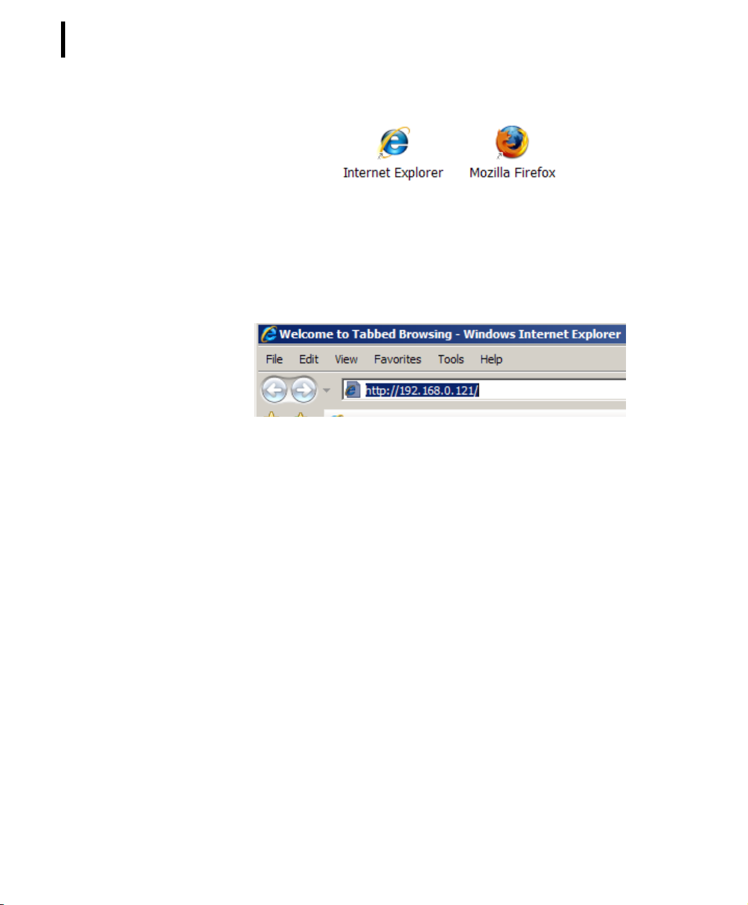
The Browser will be symbolized on the PC by an appropriate Icon:
Page 34
CHAPTER 2
34
System Setup
Figure 6. Web Browser Icon
The next step to enable the communication between your PC and
the A850 is the input of the IP address in the web browser which
you have settled as the IP address of your A850 in the Console
Command Setup (see Chapter 5).
Figure 7. Web Browser - Entry of IP address
Note: The default IP address for accessing the GUI is
- 192.168.0.1 via the LAN and
- 192.168.1.1 via the console.
Note: For the screen shots in this manual, the IP address
192.168.0.121 was chosen.
The way how to connect the PC via browser to the Gateway
depends now on a detail of the initialization which you made in the
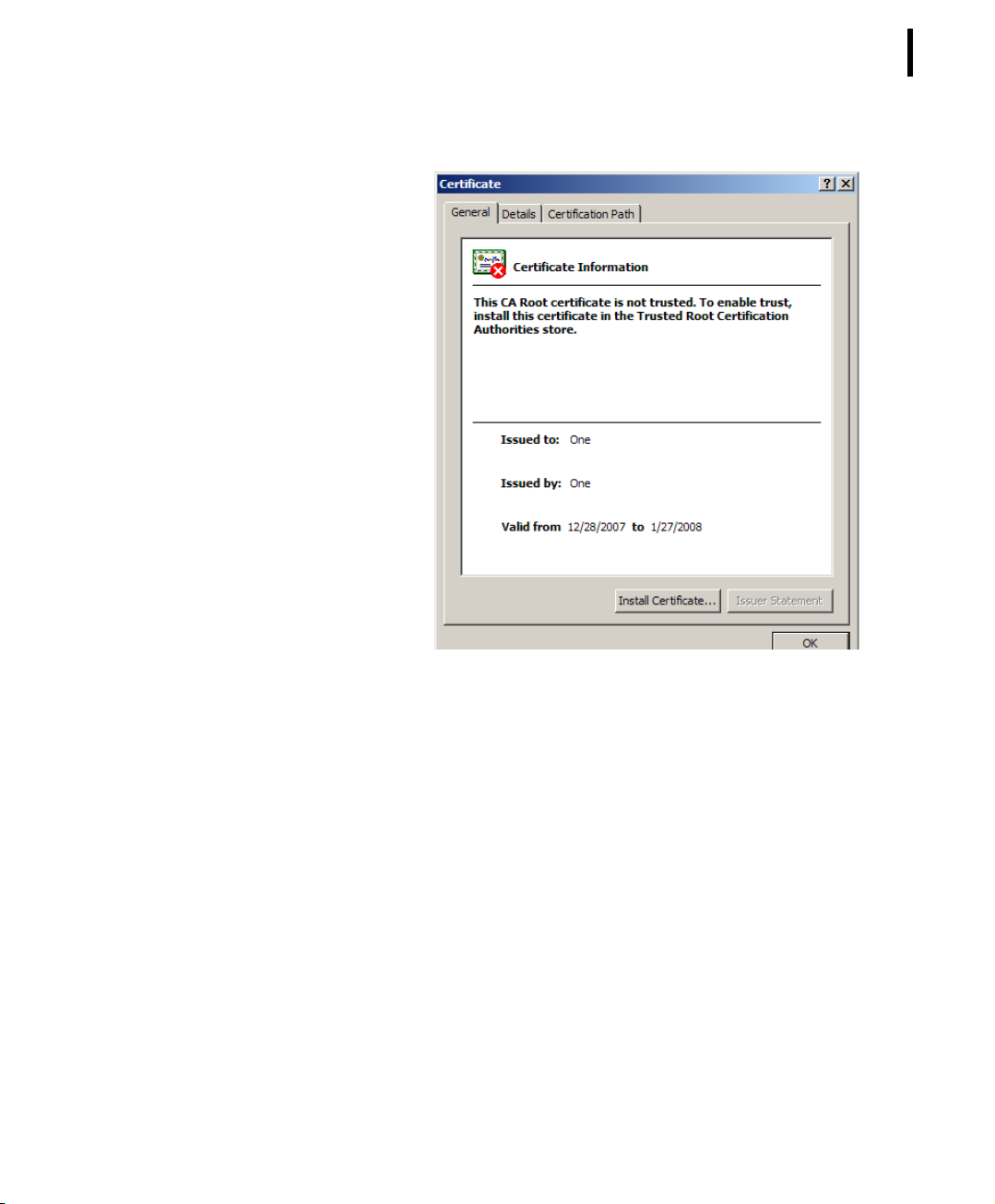
Console Command Setup: if you have generated a HTTPS certificate, you have now to put in https://IP address/ within the Web
Browser, and after the first contact via HTTPS, you have to install
the certificate in your workstation to validate it.
Page 35
CHAPTER 2
Installation
35
Figure 8. Install Certificate
If you have not generated a HTTPS certificate, you have to put in
http://IP address/in order to initiate the communication.
In any case, the internal Web Page of the A850 will appear.
Note: For security reasons, it is strongly recommended that you
always use an HTTPS connection if you communicate via
internet.
Page 36
CHAPTER 2
36
System Setup
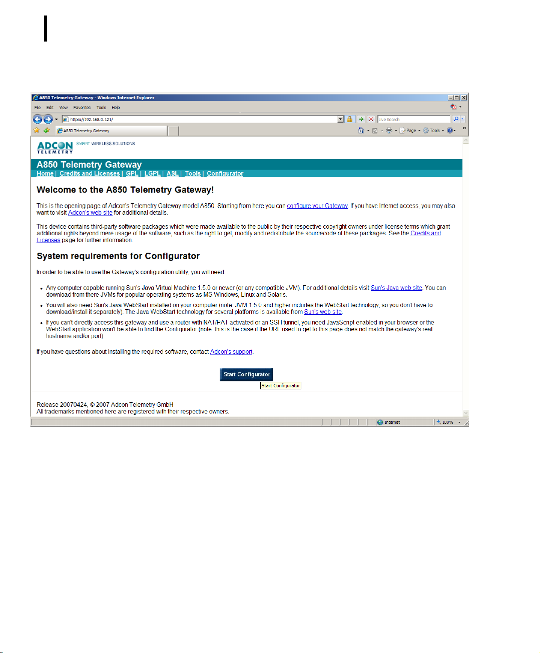
Figure 9. A850 Web Site via HTTPS with Valid Certificate
As you can see in Fig. 9, a closed keylock appears in the address
line of the browser if you connect your Gateway through a secure
HTTPS link. An open keylock means that the HTTPS certificate has
not been validated. No keylock will be displayed if you use a simple non-encrypted HTTP link.
In order to be able to use the Gateway's configuration utility, you
will need:
• Any computer capable running Sun's Java Virtual Machine
1.5. or newer (or any compatible JVM). For additional details,
please visit Sun's Java web site. You can download from there
Page 37
CHAPTER 2
Installation
JVMs for popular operating systems as MS Windows, Linux
and Solaris. We strongly recommend the use of the actual
JVM version (1.6 at the date of document release).
• You will also need Sun's Java WebStart installed on your
computer (note: JVM 1.4 and higher includes the WebStart
technology, so you don't have to download/install it
separately). The Java WebStart technology for several
platforms is available from Sun's web site.
• If you can't access this Gateway directly, using a router with
NAT/PAT activated or an SSH tunnel, you need JavaScript
enabled in your browser, else the WebStart application will
not be able to find the Configurator (note: this is the case if
the URL used to get to this page does not match the
Gateway's real hostname and/or port).
If the requirements postulated above are fulfilled, the GUI of the
Configurator can be loaded and opened by clicking the button
37
Figure 10. Start A850 Configurator
The click on this button starts the download of the A850 Configurator to your workstation (if it does not yet exist there) and starts it.
While the Configurator is loaded, you will see
Figure 11. Loading A850 Configurator
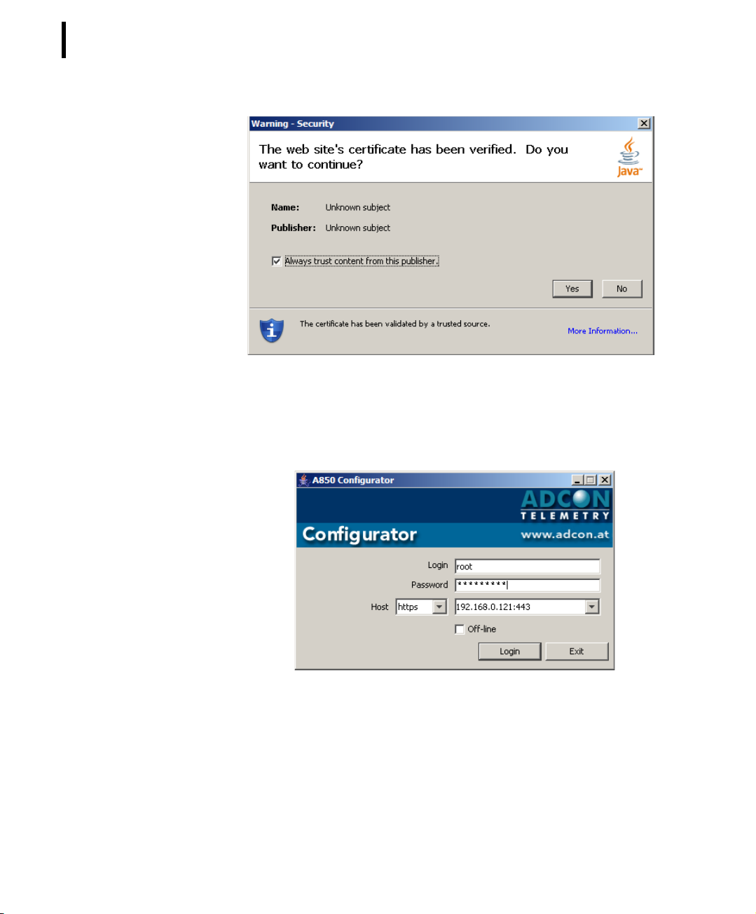
Note: At the first start of the Configurator, a security warning of
the Java Virtual Machine is issued. Please check the box
“Always trust content from this publisher” if you are sure
that you are connected to your A850. Then, acknowledge
the start of the Configurator by clicking the button “Yes”.
Page 38
CHAPTER 2
38
System Setup
Figure 12. Java Virtual Machine Security Warning
Login Procedure
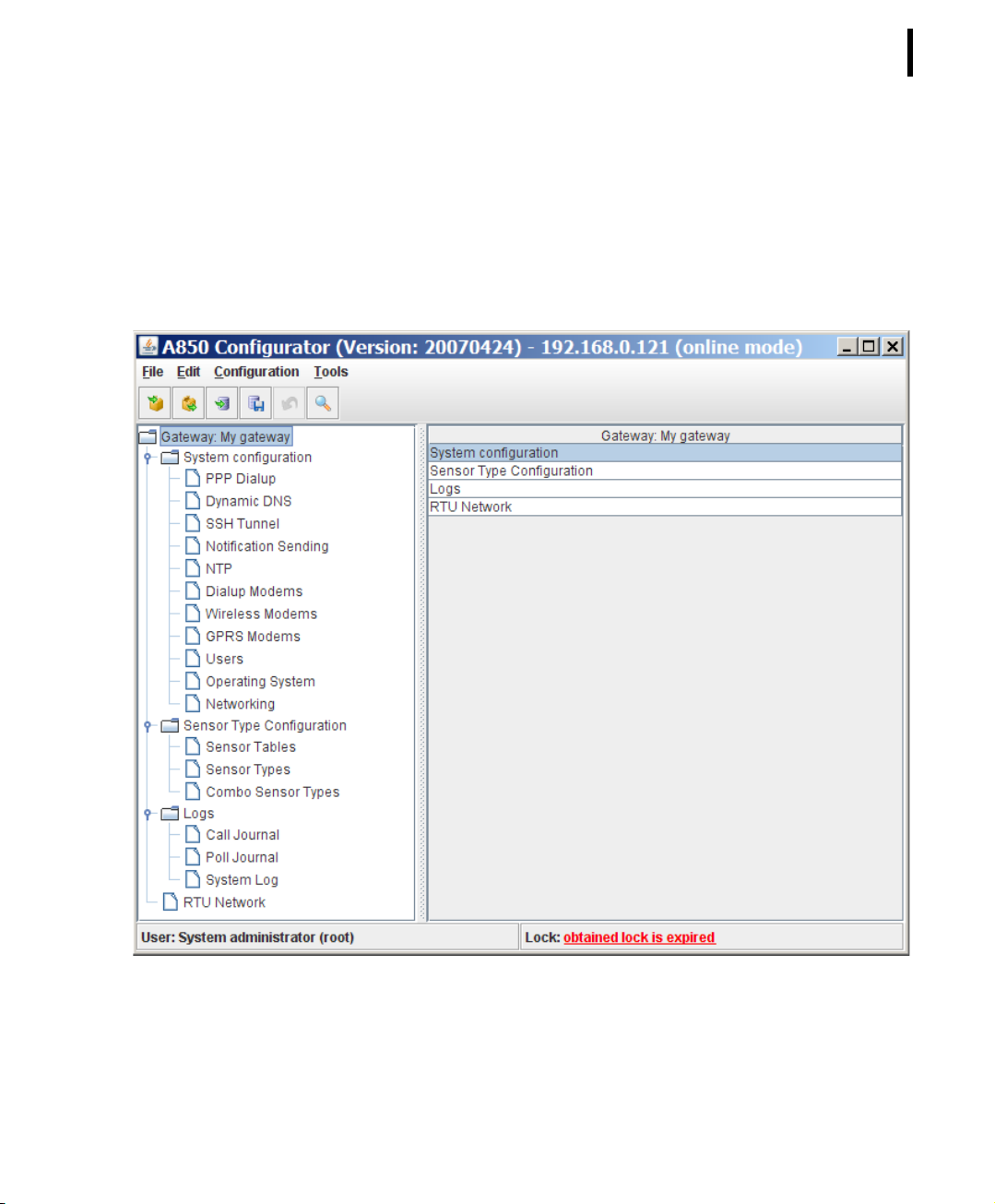
Now, the login window of the Configurator will appear:
Figure 13. A850 Login Window
At this point, you have to fill in the User Name and the Password
for logging in. The host is already predefined with the address and
the type of communication, in analogy to the A850 web site.
Note: For security reasons, if you are working via internet, you
should always choose a HTTPS connection for logging into
the Configurator.
Page 39
CHAPTER 2
Installation
In this application mode, do not click the check box “Off-line” as
this is only for the use of the Configurator on the PC in standalone-mode, i.e. without having an A850 connected.
After putting in the proper Login data and clicking the Login button, it will just take a little time until the GUI of the Configurator of
the A850 will appear:
39
Figure 14. Main Window of the A850 Configurator
Page 40

CHAPTER 2
40
System Setup
Principles of GUI operation
This chapter explains the principles of the GUI operation. A
detailed description of the workflow will be given in Chapter 3.
The main window
The main window of the A850 configuration GUI consists in the following components (see Fig. 14):
• A title bar (the header) including the actual release of the A850 as
well as the local IP address which has been set. The IP address represented in the header may differ from the address used as input in
the internet browser: this is the case if the A850 is placed in a LAN
behind an internet gateway (not an Adcon component). Please
contact your Network administator for setting up the internet gateway.
• A menu bar including the menus to invoke the provided functions.
• A tool bar providing shortcut access to specified functions. It is
possible to customize the tool bar; this is helpful because the
defined tool symbols allow quick access to specific functions which
are harder to reach through the “regular” menu structure.
• Tree view providing access to all the objects of the actual configuration to be configured.
• Table view with a configurable column display to provide sufficient information to identify the object to be worked on, depending on the selected node of the tree view.
• Context menus for the nodes of the tree view and the rows of the
table view providing functions to be performed on the underlying
object.
From this main window, the user can start the navigation to either
detailed views of objects or to other windows for issueing special
functions or to the extended search interface for retrieving a limited view of objects.
Page 41
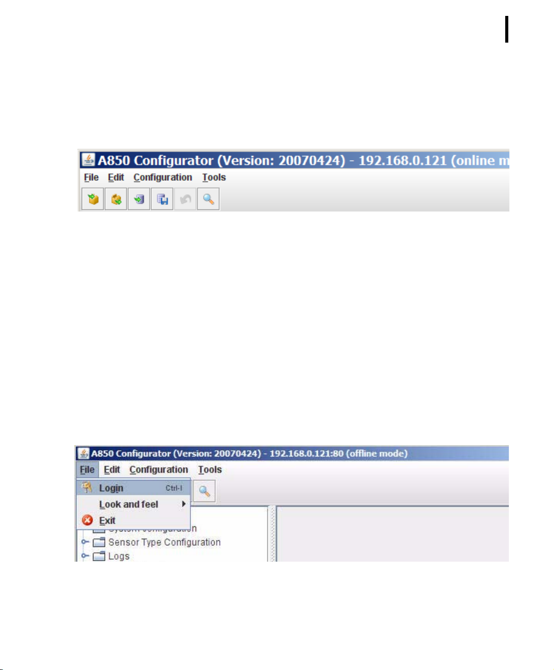
Fig. 15 shows the header, the menu bar and the tool bar of the
main window of the GUI in detail.
Commands on the Menu Bar
File Commands
Principles of GUI operation
Figure 15. Title Bar, Menu Bar, Tool Bar
CHAPTER 2
41
FileLogin
If you have worked in the Offline mode (locally on your PC without
communication to an A850), you can always change to the Online
mode by logging in, and then, you can forward the results of your
offline work to your A850 with an “update” command. This means
that you can prepare details of the configuration of your A850 in a
convenient way on your PC away from your A850 which may even
work at the same time in another configuration.
Figure 16. Login Menu Item
Page 42
CHAPTER 2
42
System Setup
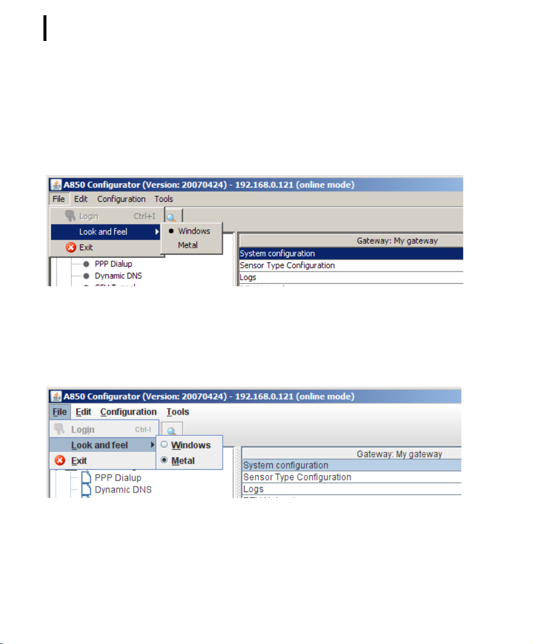
FileLook and feel
“Look and feel” allows you to change the looks of your GUI windows. You can select the aspect variant “Windows” which
assumes, automatically, the colors, symbols and other design features of your PC’s MS WINDOWS display design (as selected by
you individually)
Figure 17. Look and feel: Windows
or the aspect variant “Metal” featuring proprietary colors, symbols
and fonts:
Figure 18. Look and feel: Metal
Note: The selection of “Look and feel" has no influence on the
functions of the GUI.
Page 43
CHAPTER 2
Principles of GUI operation
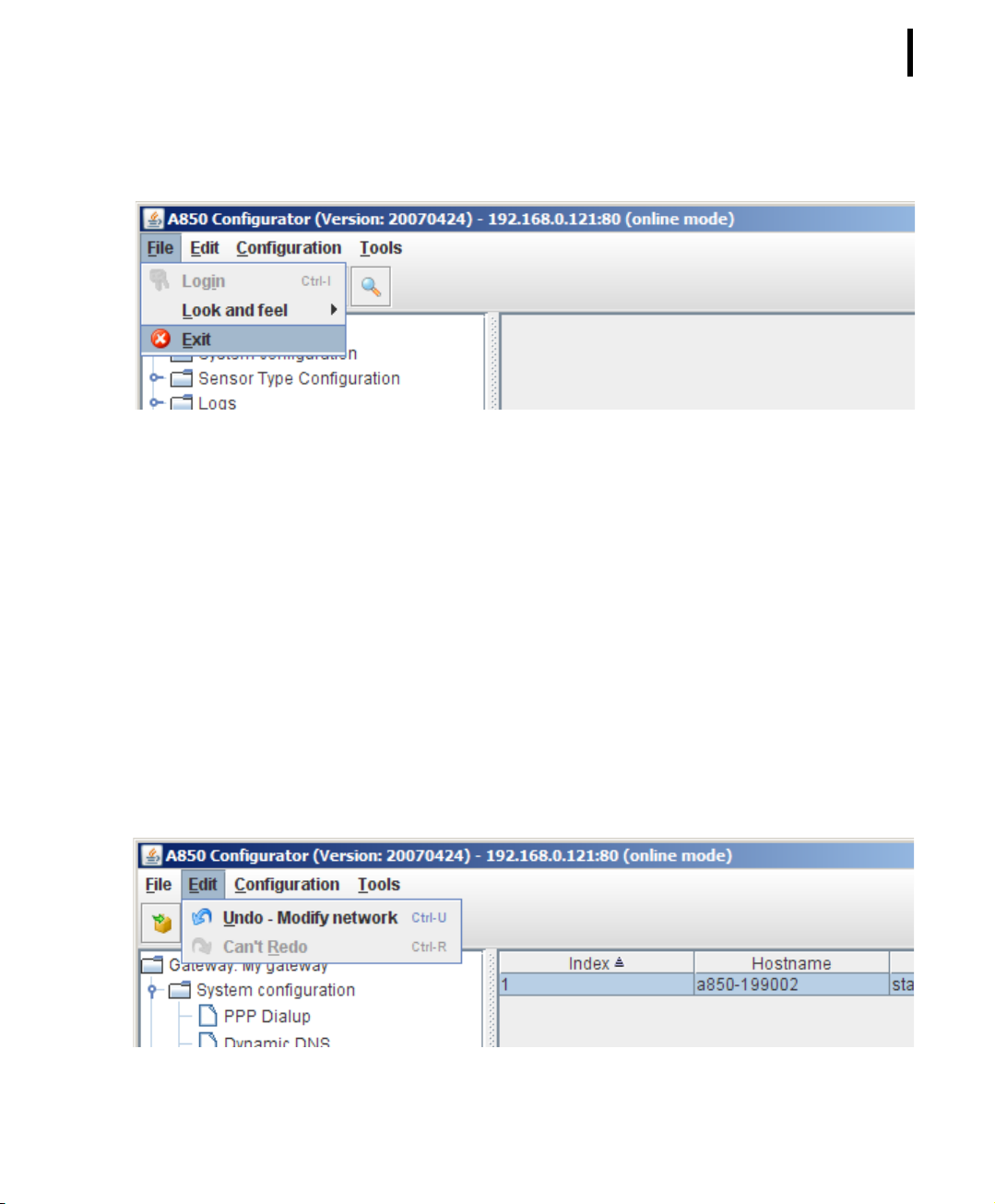
FileExit
Closes the GUI application:
Figure 19. Exit Menu Item
If you have made changes on the settings which have not been
saved in the A850 yet, you will be asked for safety reasons if you
would really like to exit without saving your changes.
43
Edit Commands
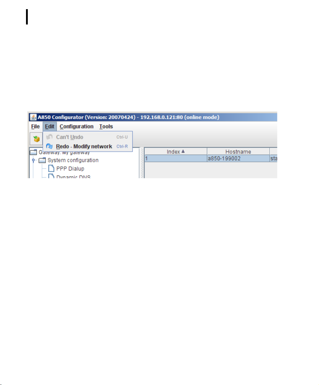
EditUndo
Changes made on the last objects representing the configuration
can be revoked by the command “Undo" (each application of the
command “Undo" revokes one change). However, this is only possible as long as you did neither execute a command “Update" or
"Refresh" because the modification state of each object is
recorded until an “Update” or “Refresh” command discards it.)
Figure 20. Undo Menu Item
Page 44
CHAPTER 2
44
System Setup
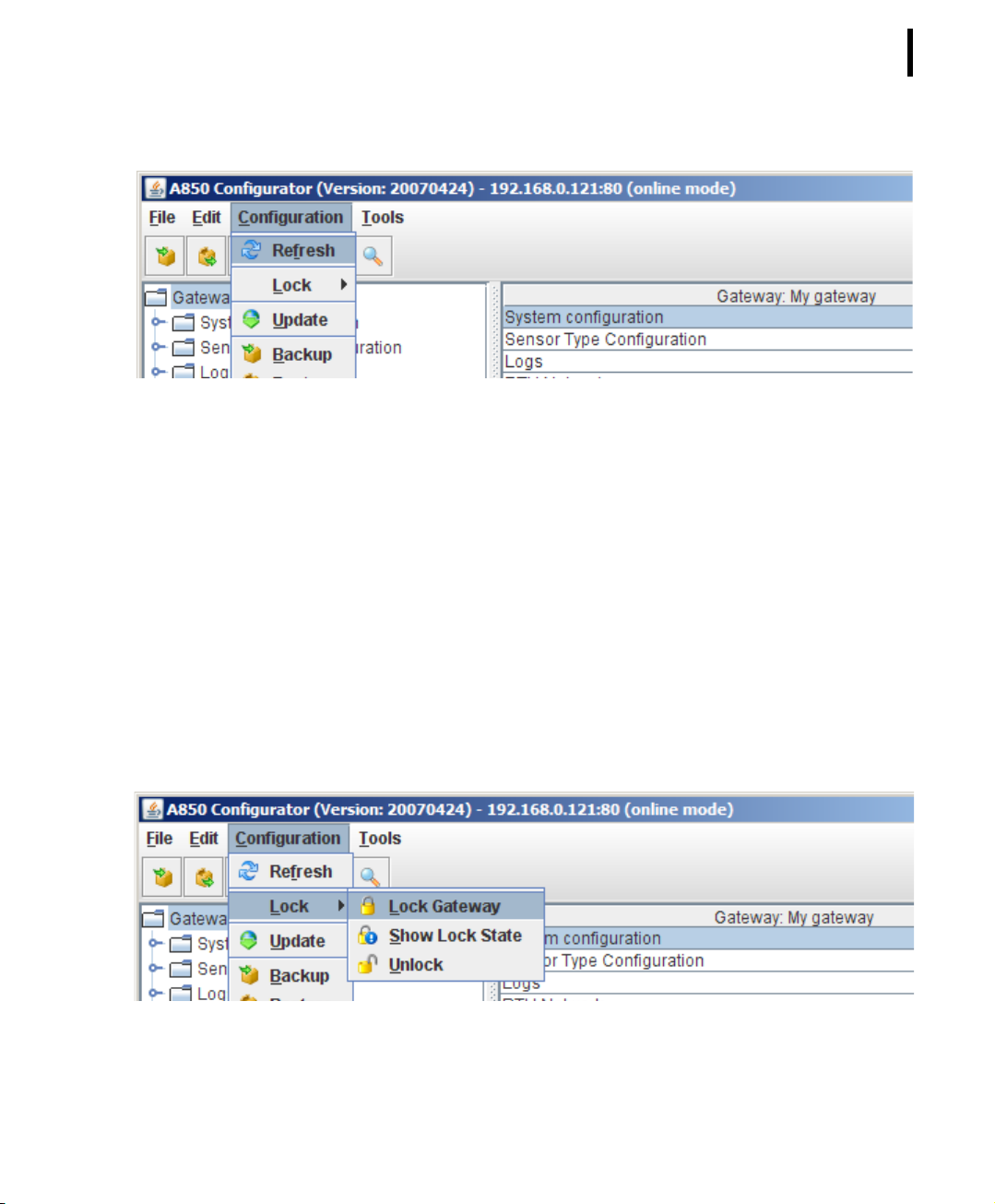
EditRedo
If you, after having revoked one or several changes by applying the
command “Undo", have changed your mind and would prefer now
to still make the changes, you can reactivate them again with the
command “Redo"(each "Redo"command reactivates one change).
However, in analogy to "Undo", this is only possible as long as you
did not apply an "Update" or "Refresh" command.
Figure 21. Redo Menu Item
Configuration Commands
ConfigurationRefresh
The “Refresh” command fetches the current configuration from
the A850 Gateway to the PC running the GUI, overwriting configuration data used on the PC up to that moment. The user must
answer the question if he wants to discard any changes or cancel
the action. This function is only available using the GUI in the
Online mode.
WARNING If you select the command “refresh”, all data which
have been put into the GUI will be overwritten by the data from the
A 850.
Page 45
CHAPTER 2
Principles of GUI operation
Figure 22. Refresh Menu Item
ConfigurationLockLock Gateway
This command locks the Gateway for other users to perform configuration changes.
45
The user is granted a requested lock if no other user has been
locking the Gateway configuration before. A “Lock” granted contains a timeout. After this timeout is over, the lock will be released
automatically unless it is renewed explicitly. A configurable
amount of minutes (default 2) before the automatic release time
expires, the user is warned by the GUI by the expiry reminder. This
menu item is disabled (greyed out), when (and as long as) a lock is
held.
Figure 23. Lock Selection
Page 46
CHAPTER 2
46
System Setup
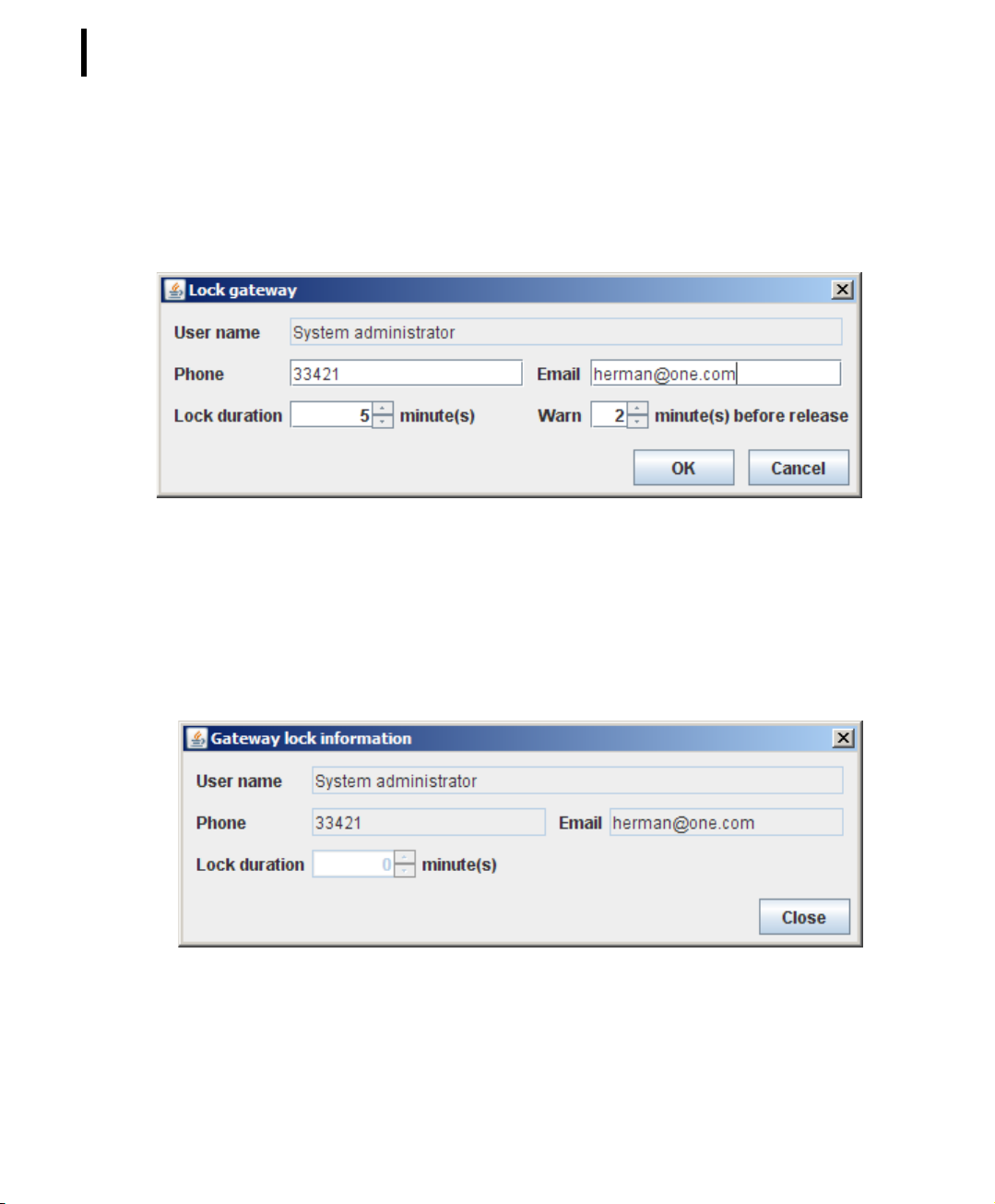
To let other users know who locked the A850 and to enable them
to contact this user if necessary, the lockholder is obliged to enter
his phone number and email address. The information about the
lockholder is displayed if you select “Show Lock State”.
Figure 24. Lock Gateway Window
ConfigurationLockShow Lock
This command displays the information about the current lock of
the Gateway.
Figure 25. Show Lock Window
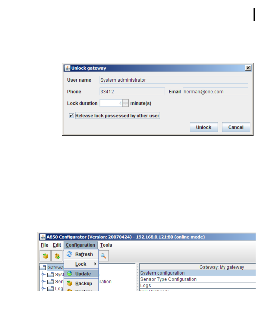
ConfigurationLockUnlock
This command allows the owner of a lock or the user of the type
“root” or “admin” (check box must be activated) to release the
Page 47
CHAPTER 2
Principles of GUI operation
current lock of the Gateway. This menu item is disabled (greyed
out), when (and as long as) no lock is held.
Figure 26. Unlock Window
47
ConfigurationUpdate
The “Update” command writes the changes done by the configuration user to the A850 Gateway. To be able to update the configuration, the user must be the holder of the current lock of the
Gateway. The function is only available using the configuration
GUI in the Online mode.
Note: The rights to perform an “Update” command are granted
only the system administrator (user “root”).
Figure 27. Update Selection
Page 48
CHAPTER 2
48
System Setup
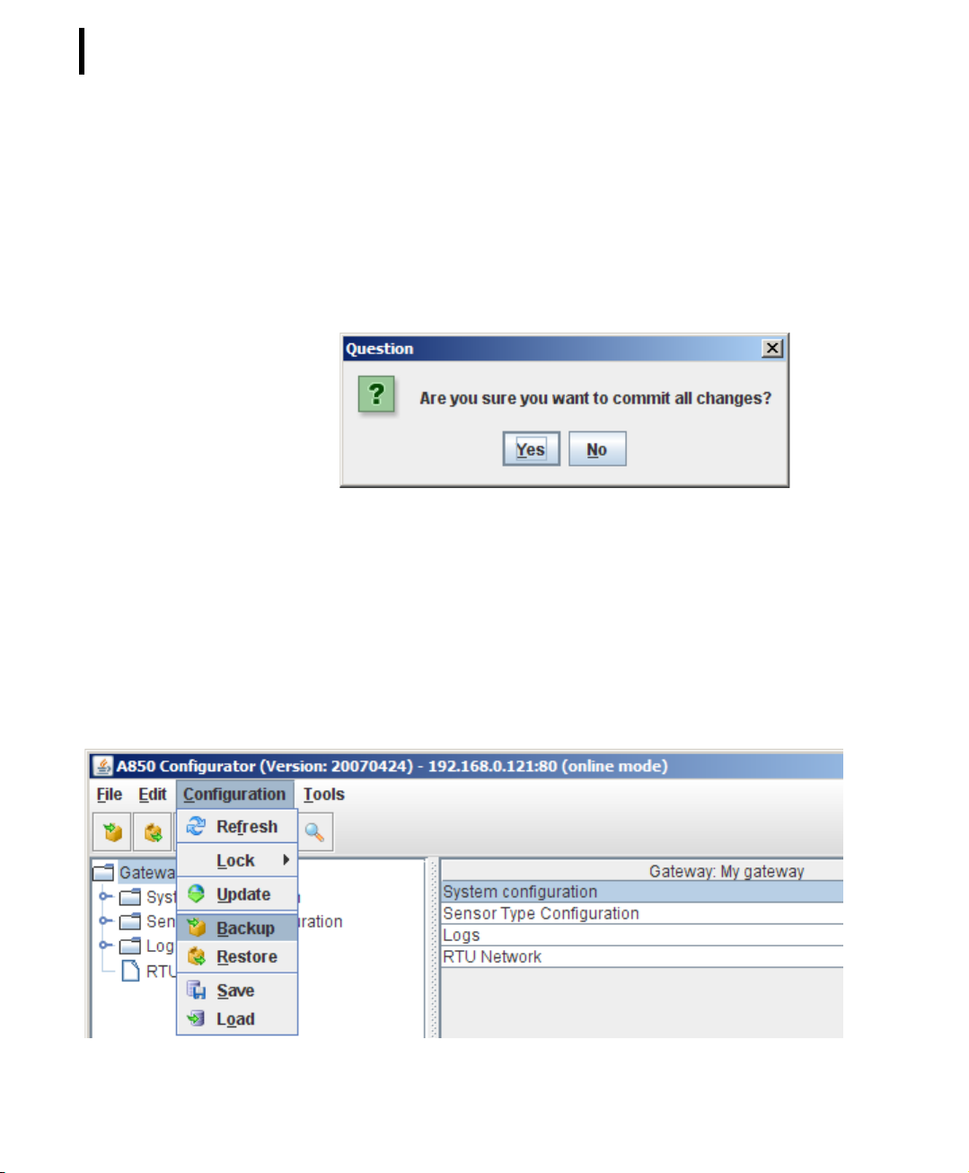
After choosing “Update”, you will be asked first if you are sure that
you want to commit all changes (Fig. 27). In order to confirm, cklick
“Yes” and the data will be transferred from the GUI to the A850.
WARNING If you confirm by clicking “Yes”, the data having been
stored in the A850 will be overwritten by the data from the GUI.
Figure 28. Update Question
ConfigurationBackup
The command “Backup” allows you to save the data from the
A850 locally on your PC, giving you the opportunity to replay these
data later again into the A850 by the command “Restore” which
allows you to reestablish the state stored by “Backup”.
Page 49
CHAPTER 2
Principles of GUI operation
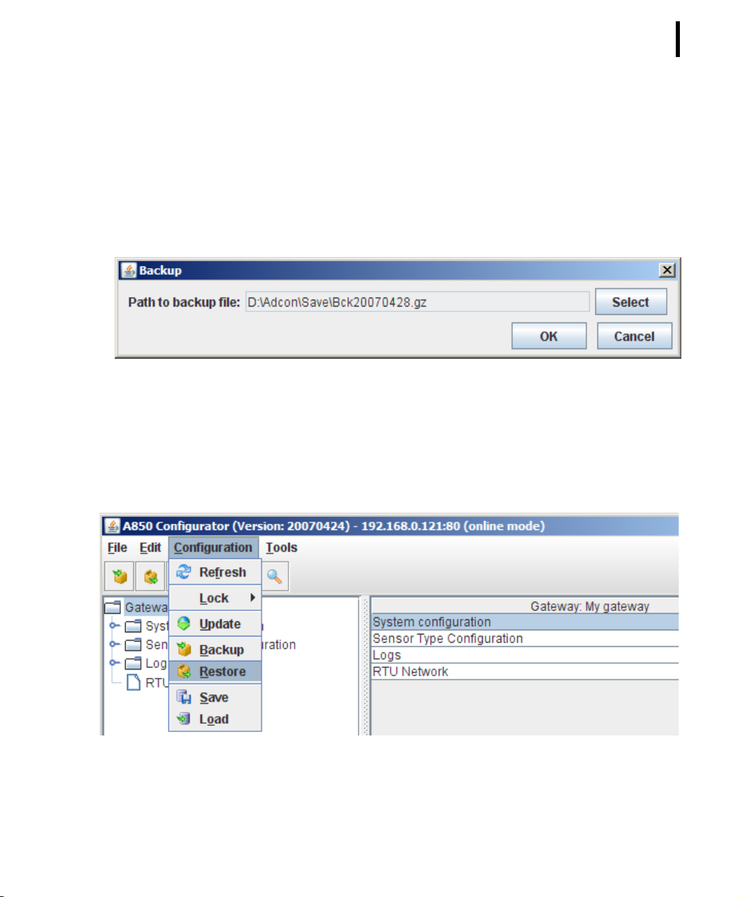
Figure 29. Backup Selection
In order to enable the data to be saved, you must choose a file
name by “Select”. We suggest to label the backup file by combining the name of the Base Station with the actual date as this will
make it easy to you to find the file again later.
Figure 30. Backup File Name Selection
ConfigurationRestore
The command “Restore” allows you to reload data from the A850
saved by the command “Backup” on your PC again into the A850
if you want to reestablish a certain state of the A850.
49
Figure 31. Restore Selection
Page 50
CHAPTER 2
50
System Setup
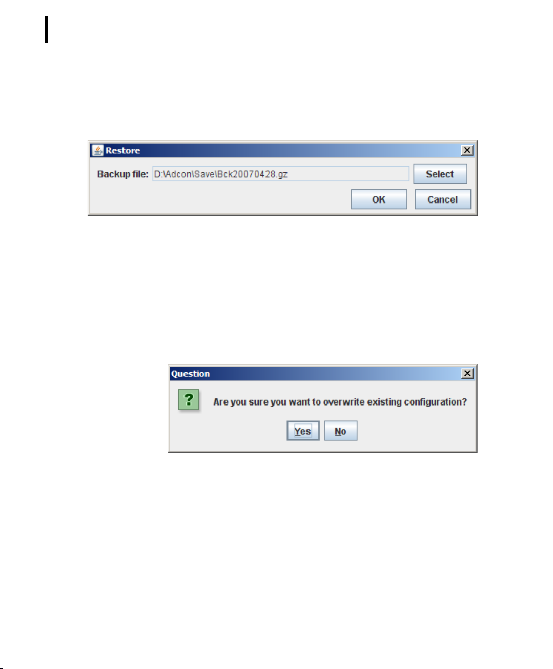
In order to be able to replay data again into your A850 by using
the command “Restore”, you have to choose the appropriate file
on your PC by “Select” and then to click “OK”.
Figure 32. Restore File Name Selection
Then, you have to confirm that you want to replay the data into
your A850.
WARNING If you confirm by “Yes”, the data stored in the A850
will be overwritten by the corresponding data from the selected
file.
Figure 33. Restore Question
ConfigurationSave
If you are using your PC to work on the configuration of the A850
by running the GUI, the current configuration data will be held in
the RAM of your PC (which means that the data are stored in a volatile memory and that e.g. an operating system error could cause
loss of these data). By the “Save” command, the current configuration data will be stored to the local file system of your PC which will
Page 51
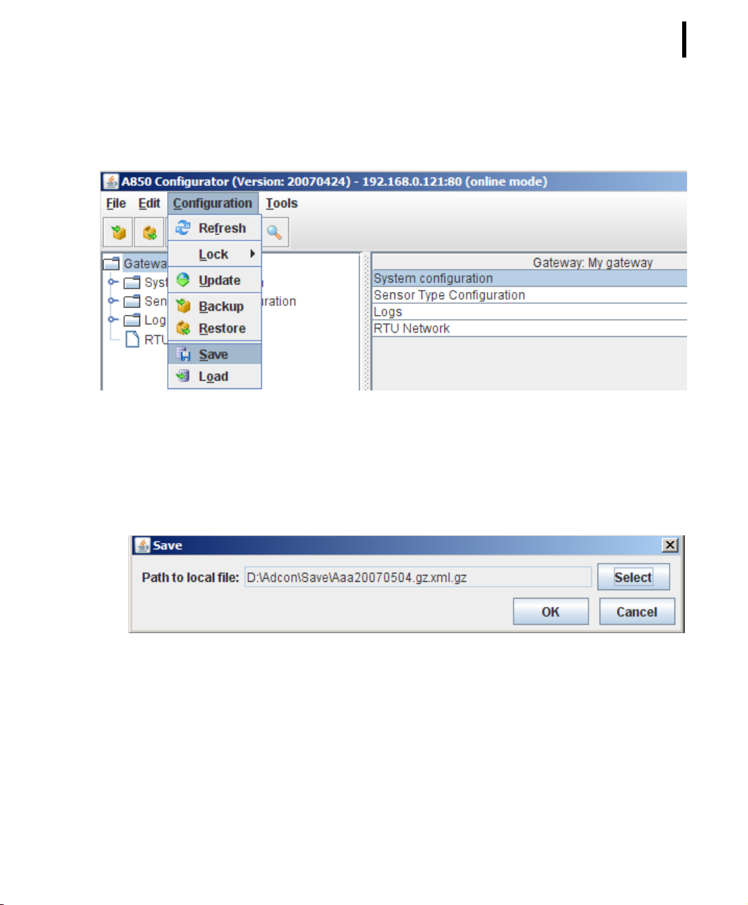
CHAPTER 2
Principles of GUI operation
usually reside on its harddisk. This function is also available using
the configuration GUI in the Offline mode.
Figure 34. Save Selection
51
In order to enable the data to be saved, you must choose a file
name by “Select”. We suggest to label the file of the GUI to be
saved by combining the name of the Base Station with the actual
date as this will help you to find the file later easily.
Figure 35. Save File Name Selection
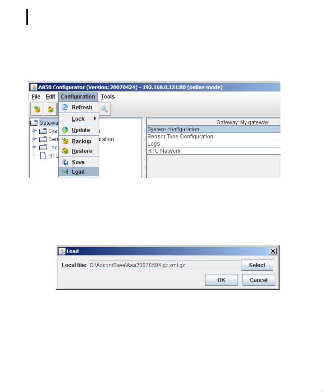
ConfigurationLoad
The “Load” command reads a file previously saved by the “Save”
function and loads it into the RAM of the PC running the A850
configuration GUI. This function is also available using the configuration GUI in the Offline mode.
Note: Each time a “Load” command is performed, the GUI
switches automatically from online mode to offline mode.
Page 52
CHAPTER 2
52
System Setup
For resuming the parameters in the A850 which have been
loaded that way, the user “root” has to give first the command “Login” and consecutively the command “Update”.
Figure 36. Load Selection
For replaying data into your GUI by using the command “Load”,
you have to choose the desired file on your PC by the command
“Select” and then to click “OK”.
Figure 37. Load File Name Selection
Page 53
CHAPTER 2
Principles of GUI operation
Tools Commands
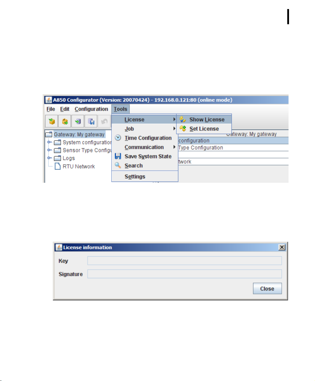
Tool sLicenseShow License
This command retrieves the current license information from the
A850 Gateway.
53
Figure 38. Show License Selection
If an additional license has been installed on your A850, it will be
displayed in this window:
Figure 39. Show License Window
Note: If there is no special license on the Gateway, the License
information window is empty.
Page 54
CHAPTER 2
54
System Setup
Tools LicenseSet License
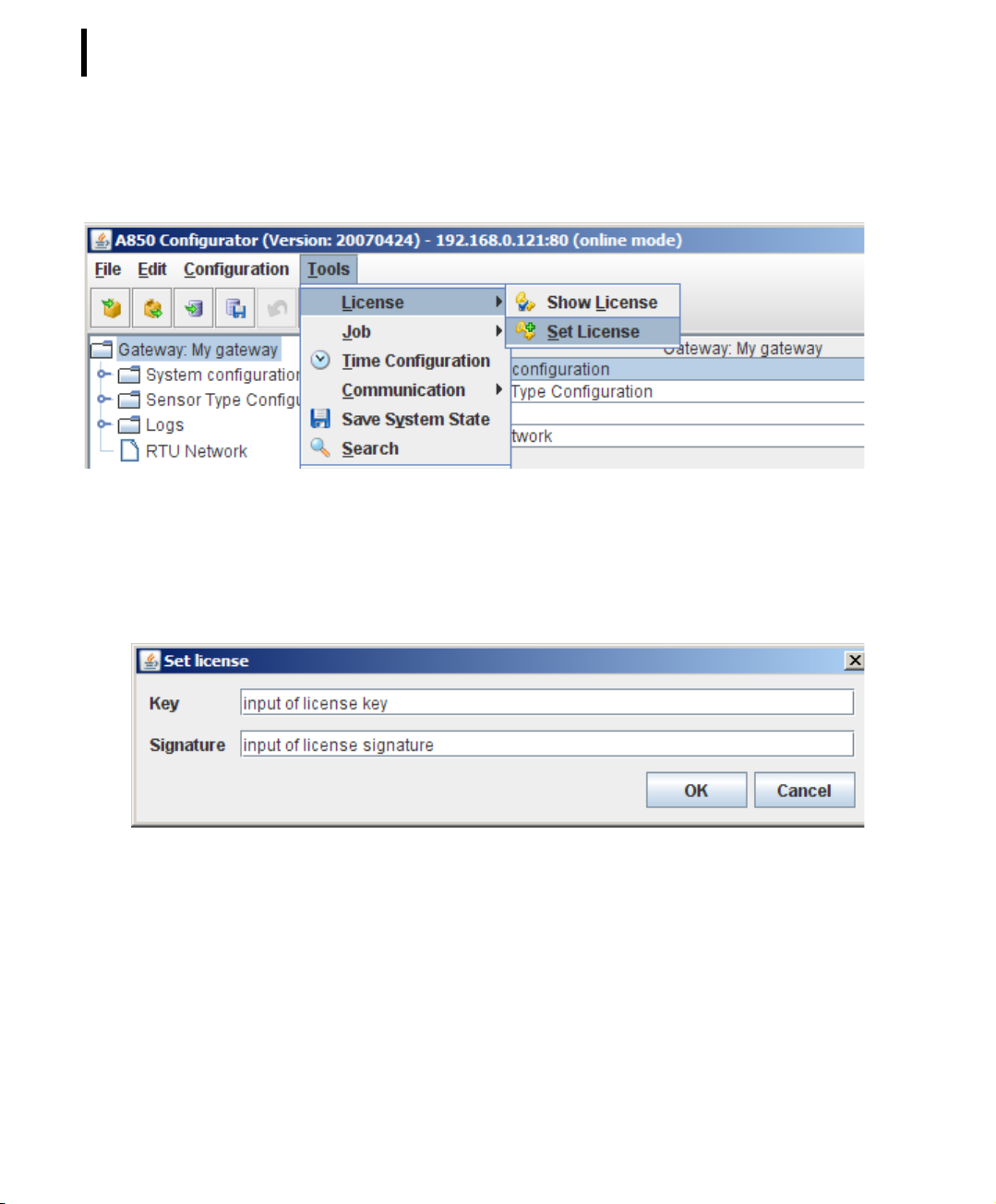
This command supports the update of the license of the A850
Gateway.
Figure 40. Set License Selection
“Set license” allows you to enter additional licenses for special
purposes by input of the license key provided by Adcon as well as
by input of the license signature.
Figure 41. Set License Window
Note: For regular operation of the Gateway, no special license is
necessary.
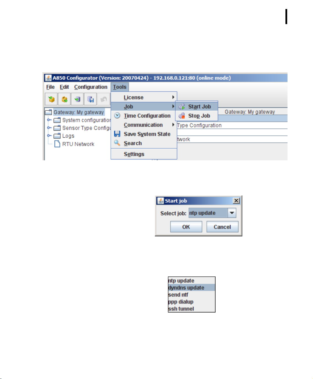
Tools Job Start Job
This command allows starting jobs manually outside of the job
scheduling selected by you in the respective detail windows. The
Page 55
CHAPTER 2
Principles of GUI operation
job to be started can be one of the names “ntp update” or
“dyndns update”, “send ntf” “ppp dialup”, and “ssh tunnel” .
Figure 42. Start Job Selection
55
The following window allows you to select the job that you want to
start,
Figure 43. Start Job Window
giving you the choice shown in Fig. 44:
Figure 44. Choose Job to Start
Page 56
CHAPTER 2
56
System Setup
Tools Job Stop Job
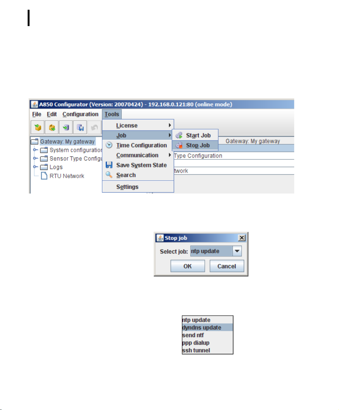
This command allows stopping jobs manually which have been
started automatically by the “job scheduling” in their repective
detail windows or which have been started manually. The job to be
stopped can bear one of the names “ntp update” or “dyndns
update”, “send ntf” “ppp dialup”, and “ssh tunnel”.
Figure 45. Stop Job Selection
The following window allows you to select the job which you want
to stop,
Figure 46. Stop Job Window
giving you - in analogy of the start job list above - the following
selection possibilities:
Figure 47. Choose Job to Stop
Page 57
CHAPTER 2
Principles of GUI operation
Tool sTime Configuration
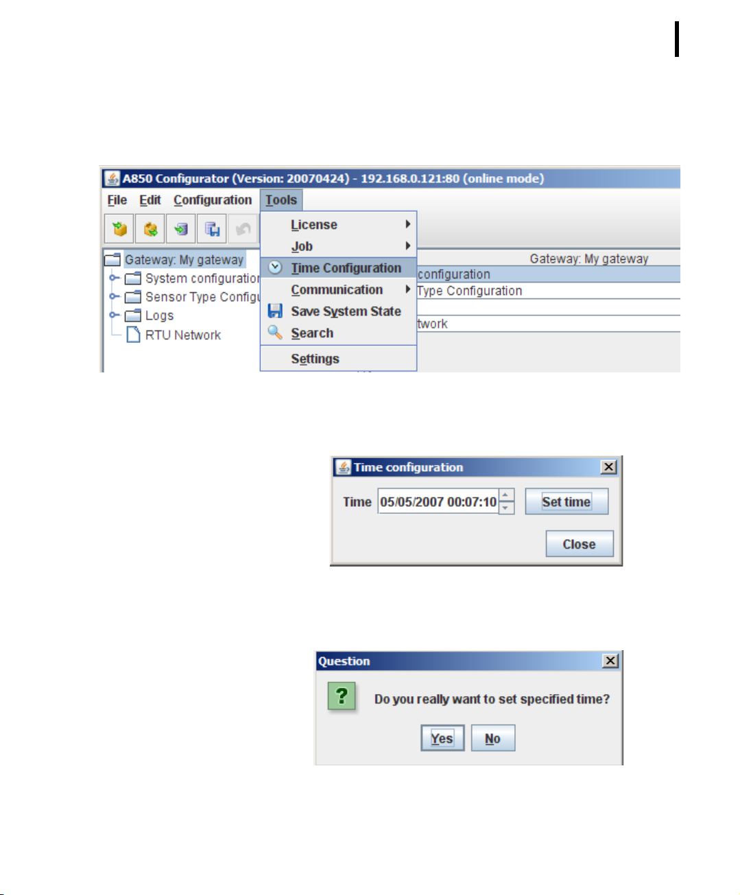
This command retrieves the current time from the Gateway and
allows also to set it to a new value.
Figure 48. Time Configuration Selection
The Time Configuration window can be used to read the actual
system time of the A850 and to correct it if necessary.
57
Figure 49. Time Configuration Window
After having corrected the time as appropriate, you will have to
click first “Set time” and then to confirm:
Figure 50. Time Update Question
Page 58

CHAPTER 2
58
System Setup
Tools CommunicationDirect Commands
For RTUs and Wireless Modems, this command allows the user to
initiate radio commands to the respective receiver and effectuates
the responses to be displayed. The user must have the “direct”
access right to the RTU for being able to use this function. Each
command is initiated by sending a “direct” request to the Gateway. Before issuing the request entered by the user, the GUI prefixes it with the ID of the targeted RTU or the Wireless Modem if it
is missing. The protocol of the commands sent and the corresponding responses are displayed by a multiline text control, but
can also be exported to a text file and printed. The lines entered
by the user are presented in bold font. The maximum number of
lines available for scrolling is configurable (1000 lines default).
Note: Direct Commands can be used depending on the RTU type
and are described in the respective RTU manuals.
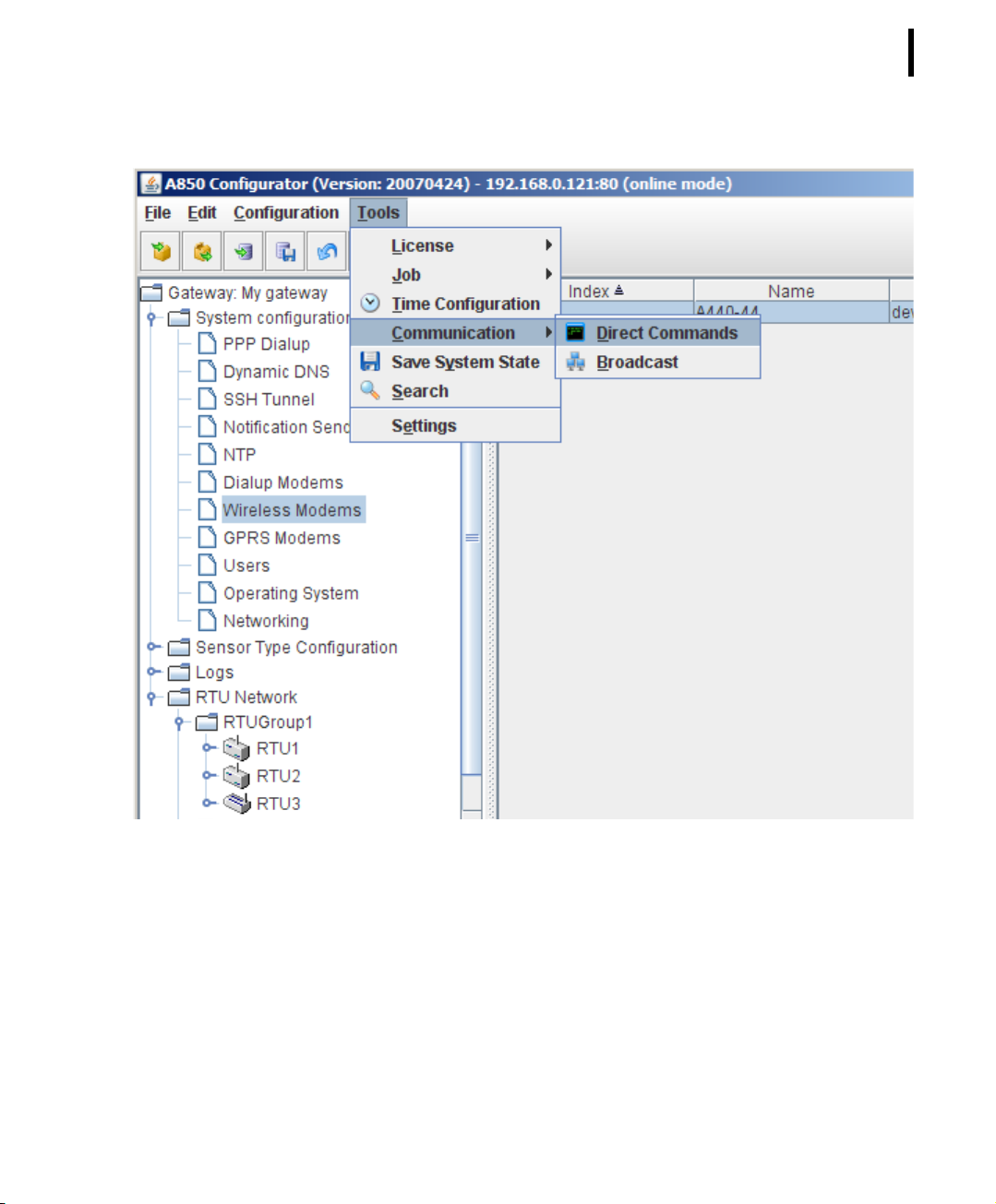
Direct commands can be sent to separate Wireless Modems. To
do this, you first have to select them in “Direct commands”, to
choose the corresponding Wireless Modem in the “Table view”
and to mark it by the mouse before you can send the command.
Page 59
CHAPTER 2
Principles of GUI operation
59
Figure 51. Direct Commands Selection for Wireless Modem
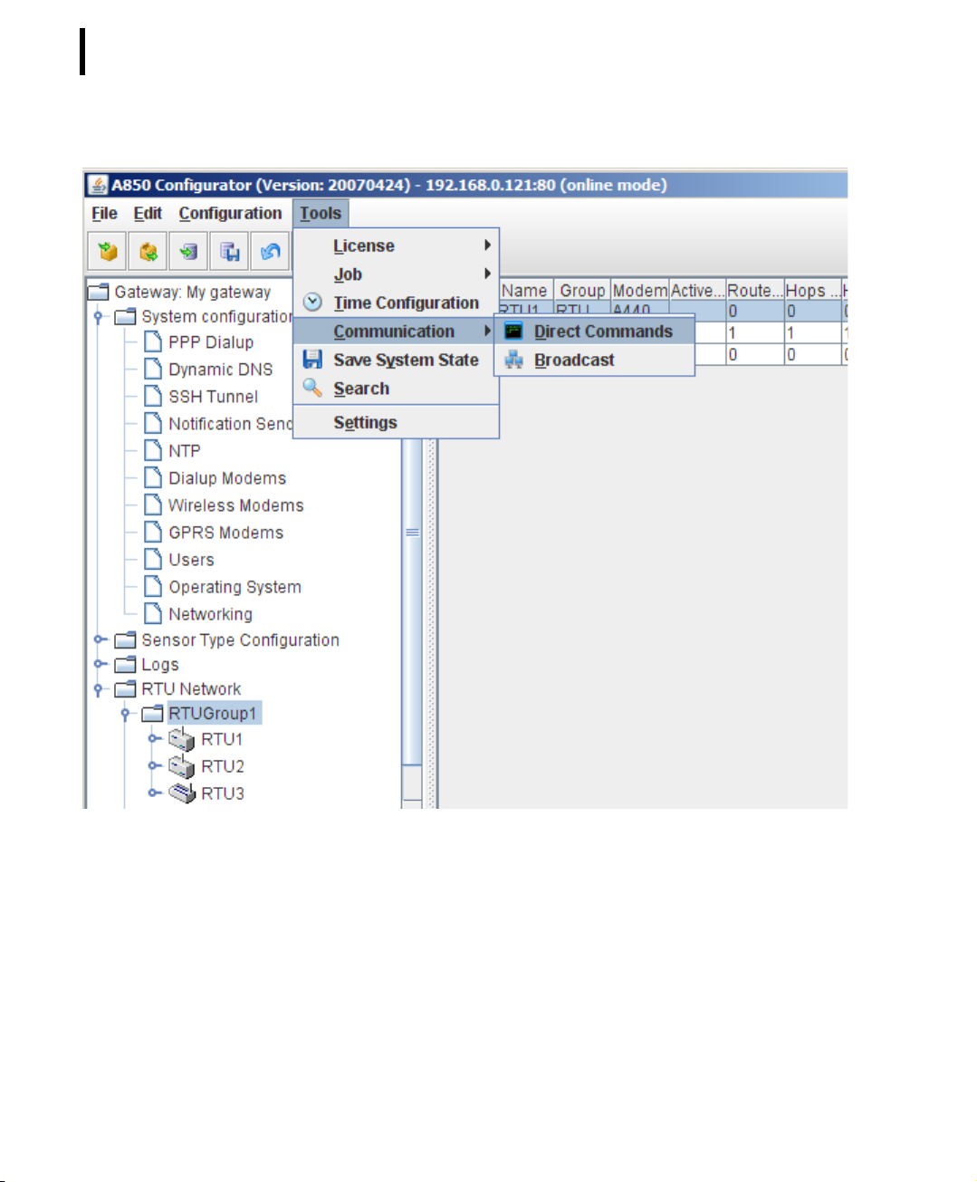
Direct commands can be sent also to a separate RTU. To do this,
you have to choose the corresponding RTU in the “Table view”
and to mark it with the mouse before selecting “Direct commands”.
Page 60
CHAPTER 2
60
System Setup
Figure 52. Direct Commands Selection for single RTU
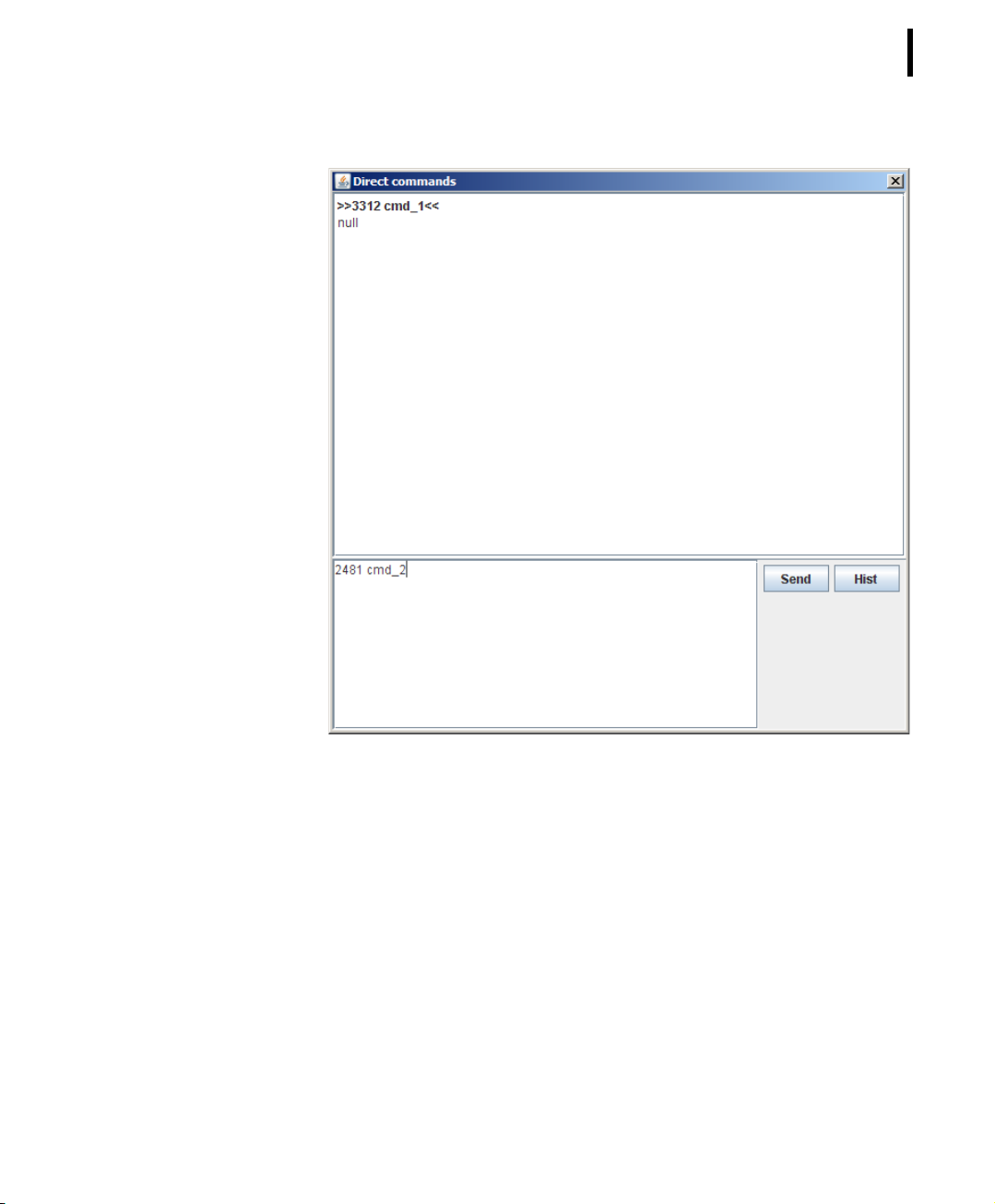
For sending a command to a Wireless Modem or to a RTU, enter
the corresponding “Direct command” in the nether window part
and click the “Send” button. This will cause the the command to
be sent to the respective device whose feedback will be received.
The sent command as well as the received feedback will be displayed in the upper window part.
Page 61
CHAPTER 2
Principles of GUI operation
61
Figure 53. Direct Command Window
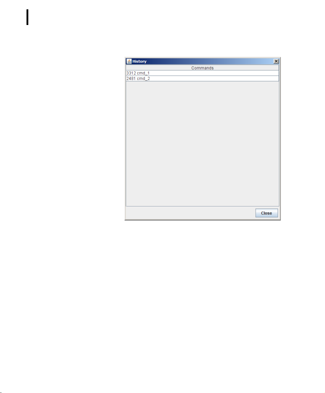
For tracking the commands already sent, click the button “Hist”
(history). This will result in list of the sent commands to be displayed in a new window.
Page 62
CHAPTER 2
62
System Setup
Figure 54. Direct Command History
Tools CommunicationBroadcast
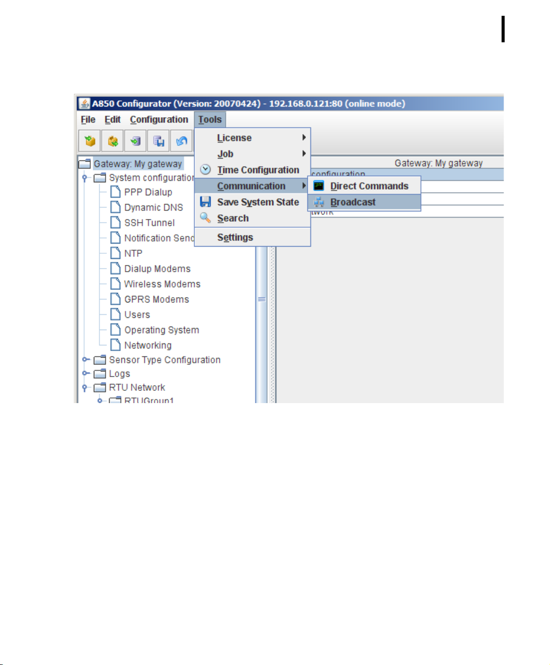
The purpose of the command “Broadcast” is to detect all RTUs
within the Wireless Network. If the command “Radio Broadcast” is
sent, all RTUs receiving this broadcast will send a feedback. Thus,
sending a broadcast allows to find out which RTUs communicate
actively with the A850 via the connected Wireless Modems.
Page 63
CHAPTER 2
Principles of GUI operation
63
Figure 55. Broadcast Selection
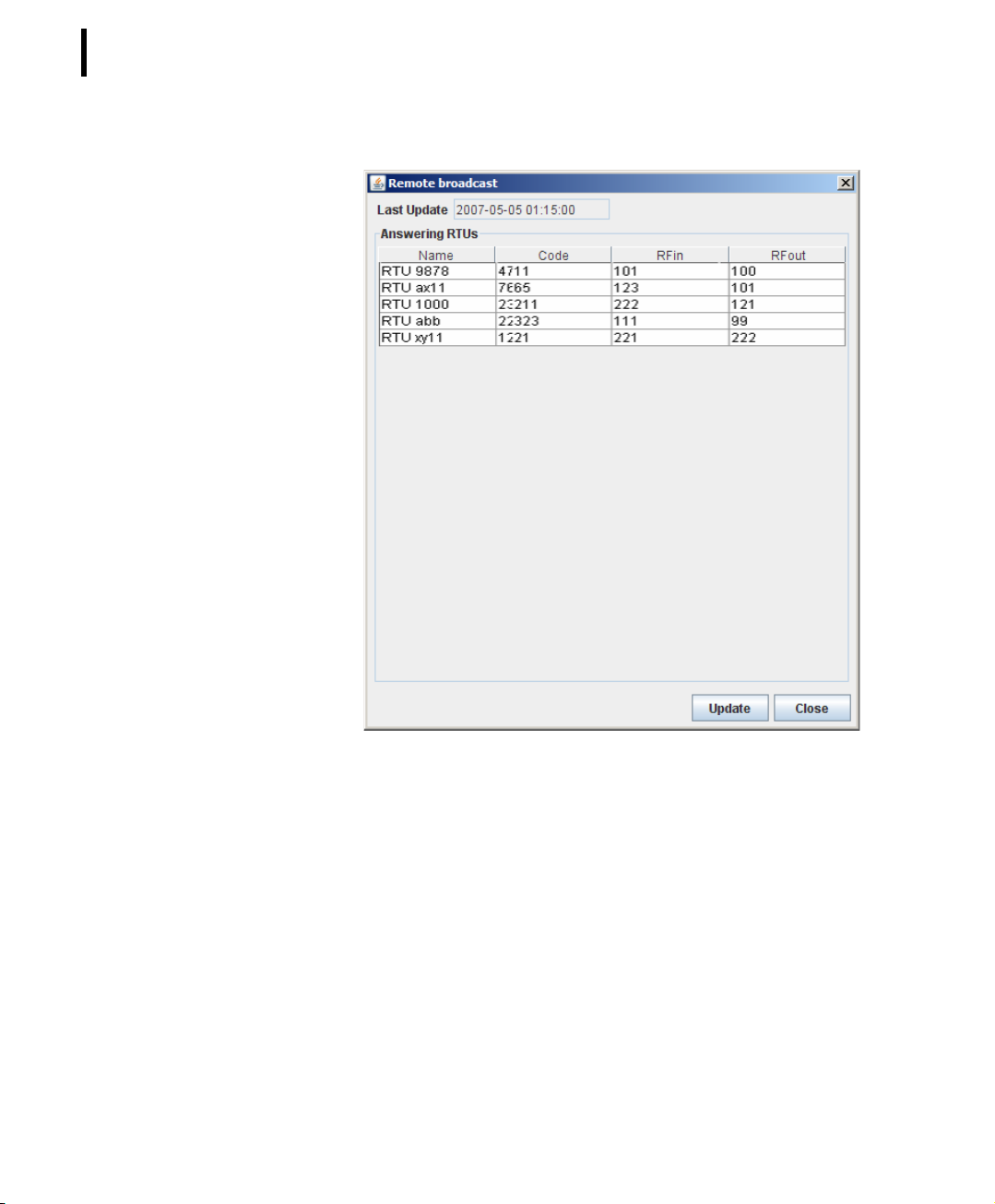
The RTUs which did respond to the broadcast will be displayed
thereafter in a list in the Remote broadcast window.
Page 64
CHAPTER 2
64
System Setup
Figure 56. Broadcast Window
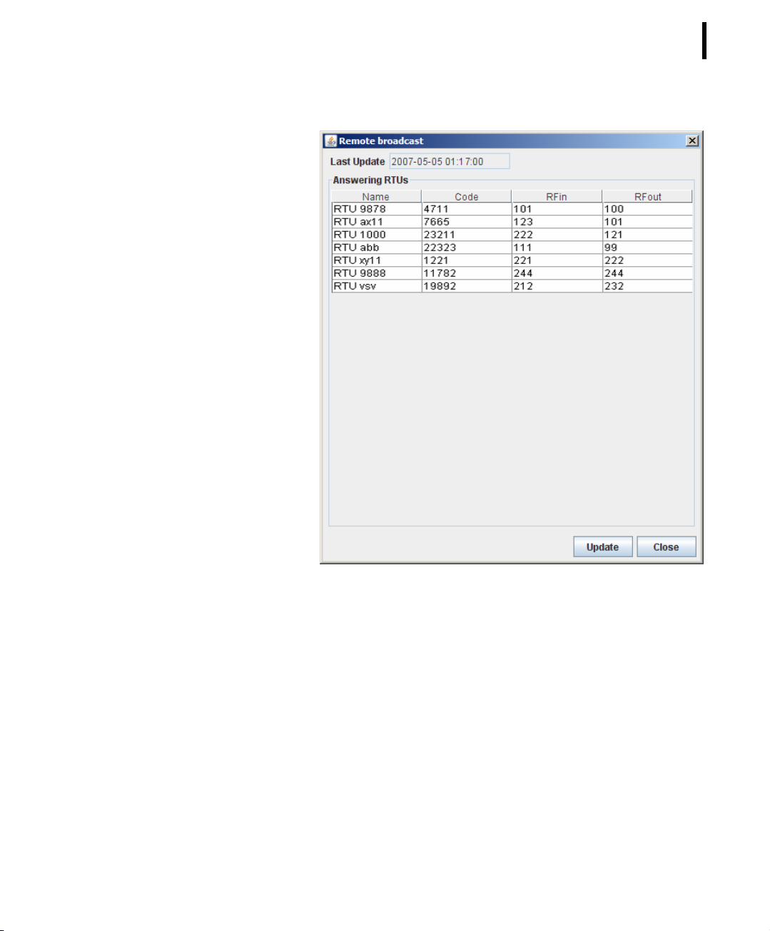
By clicking the button “Update”, another broadcast is initiated so
that changes (admissions or outages of RTUs, respectively) will be
displayed.
Page 65
CHAPTER 2
Principles of GUI operation
65
Figure 57. Broadcast Window Update
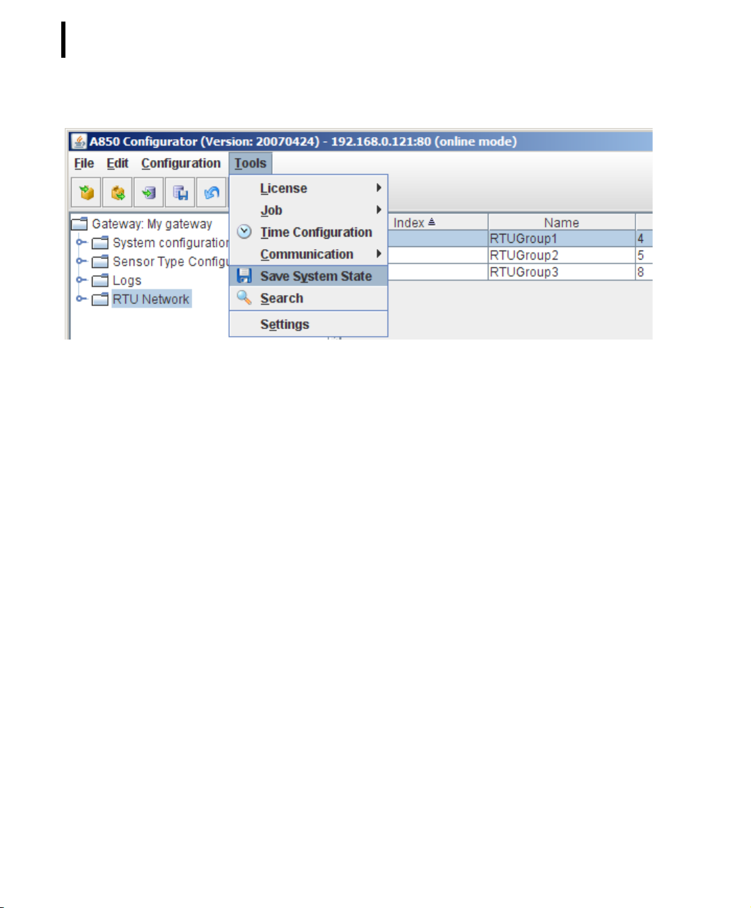
Tool sSave System State
The “Save System State” function is very useful to debug the A850
if any error or problem occurs. This command opens the interfaces
to specify the data to be stored.
Page 66
CHAPTER 2
66
System Setup
Figure 58. Save System State Selection
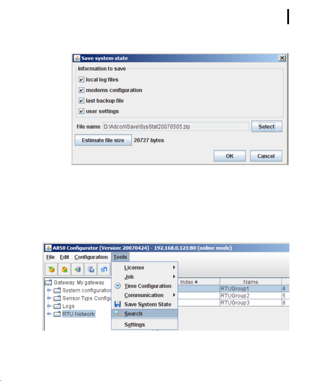
The following data can be selected in the check boxes for saving:
“local logfiles”, “modems configuration”, “last backup file” and
“user settings”. By default, all data are checked for saving.
The local log files of the activities will be stored on the selected
place.
Clicking the button “Estimate file size” allows to estimate the
approximate size of the data file to be saved on the PC.
This function is very important for reporting bugs or other problems back to experts; the stored file allows a deep analysis of the
occurred problem. In case of trouble, before doing anything else,
please use this function! If the available debugging information is
not stored this way, and if a reset is made, it will be impossible to
trace the problem later on.
Page 67
Principles of GUI operation
Figure 59. Save System State Window
CHAPTER 2
67
Tool sSearch
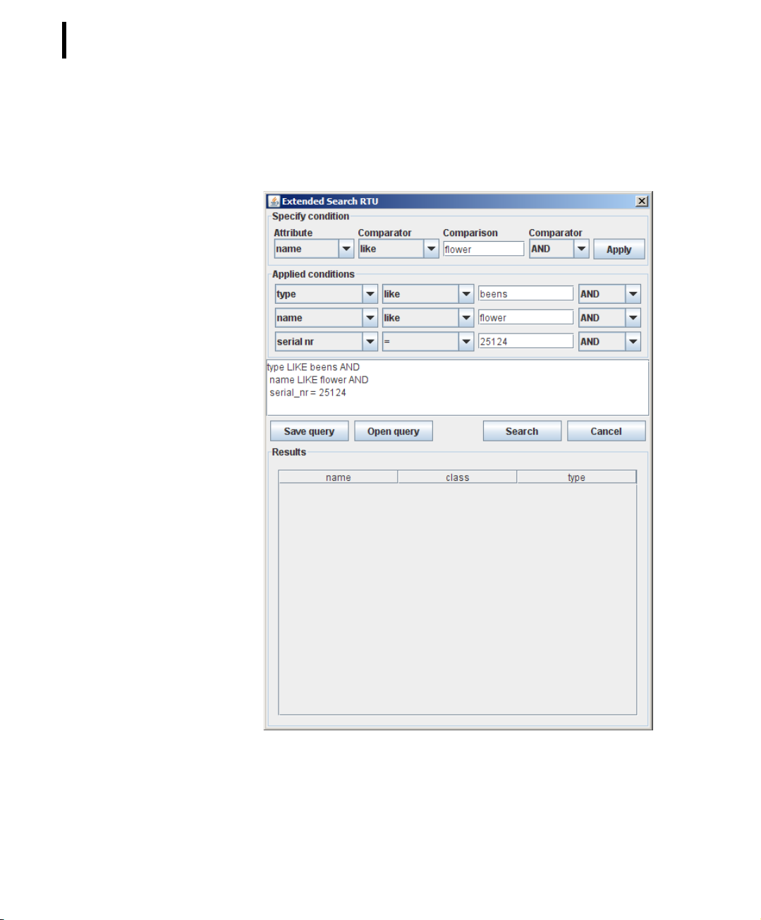
Opens the “Extended Search interface” which allows to specify
and to submit queries for retrieving a subset of RTU and sensor
objects.
Figure 60. Search Selection
Page 68
CHAPTER 2
68
System Setup
In the Search window, RTUs can be searched for according to certain selectable criteria and logical interconnections. In doing so,
also complex search queries can be created.
Figure 61. Search Window
In order to allow more complex queries to be used again in the
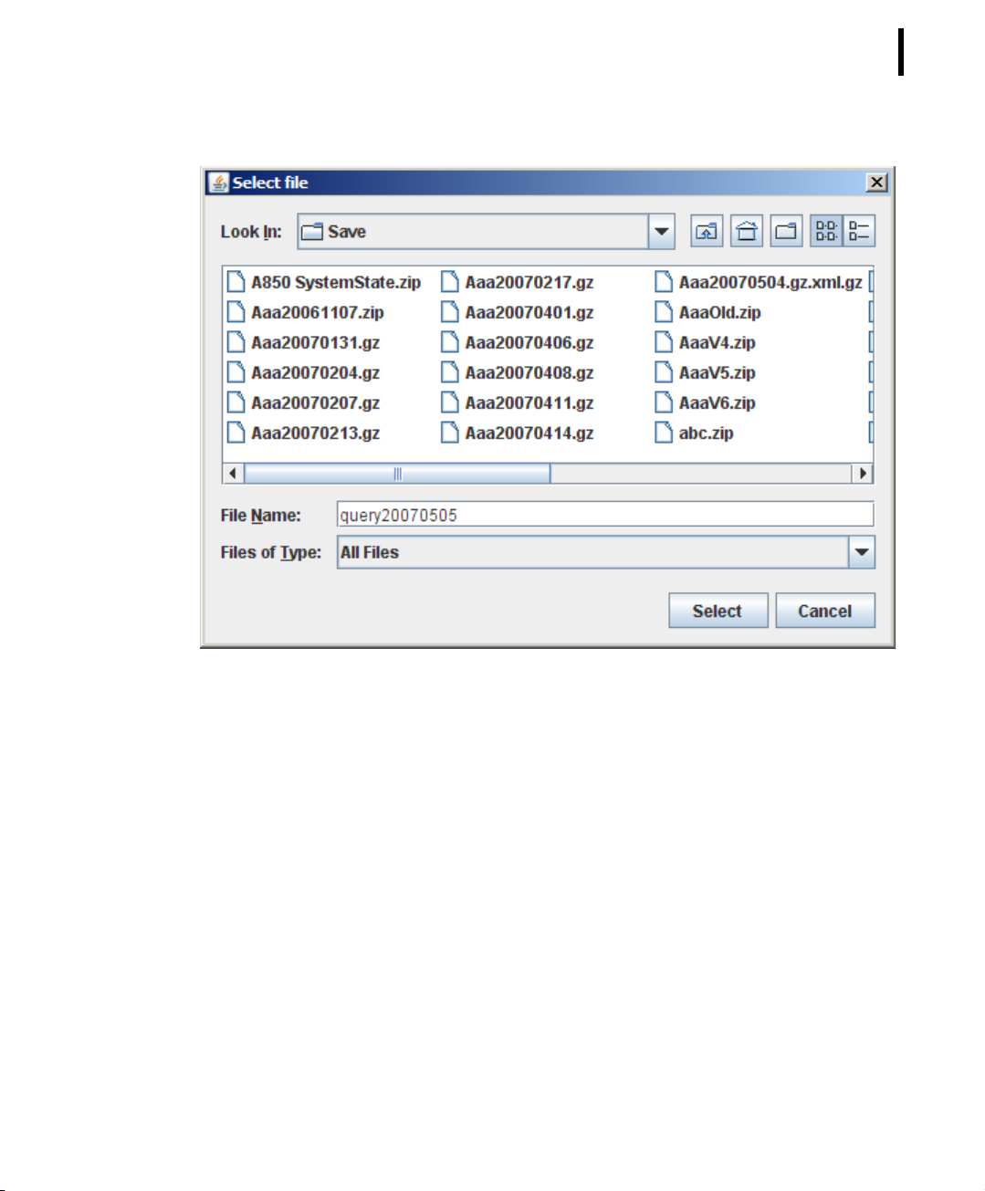
future, query dialogues can be saved by clicking the button “Save
query” (one file name has to be selected for each query). Later,
these queries can be reactivated again by “Open query”.
Page 69
CHAPTER 2
Principles of GUI operation
69
Figure 62. Search Window
Tool sSettings
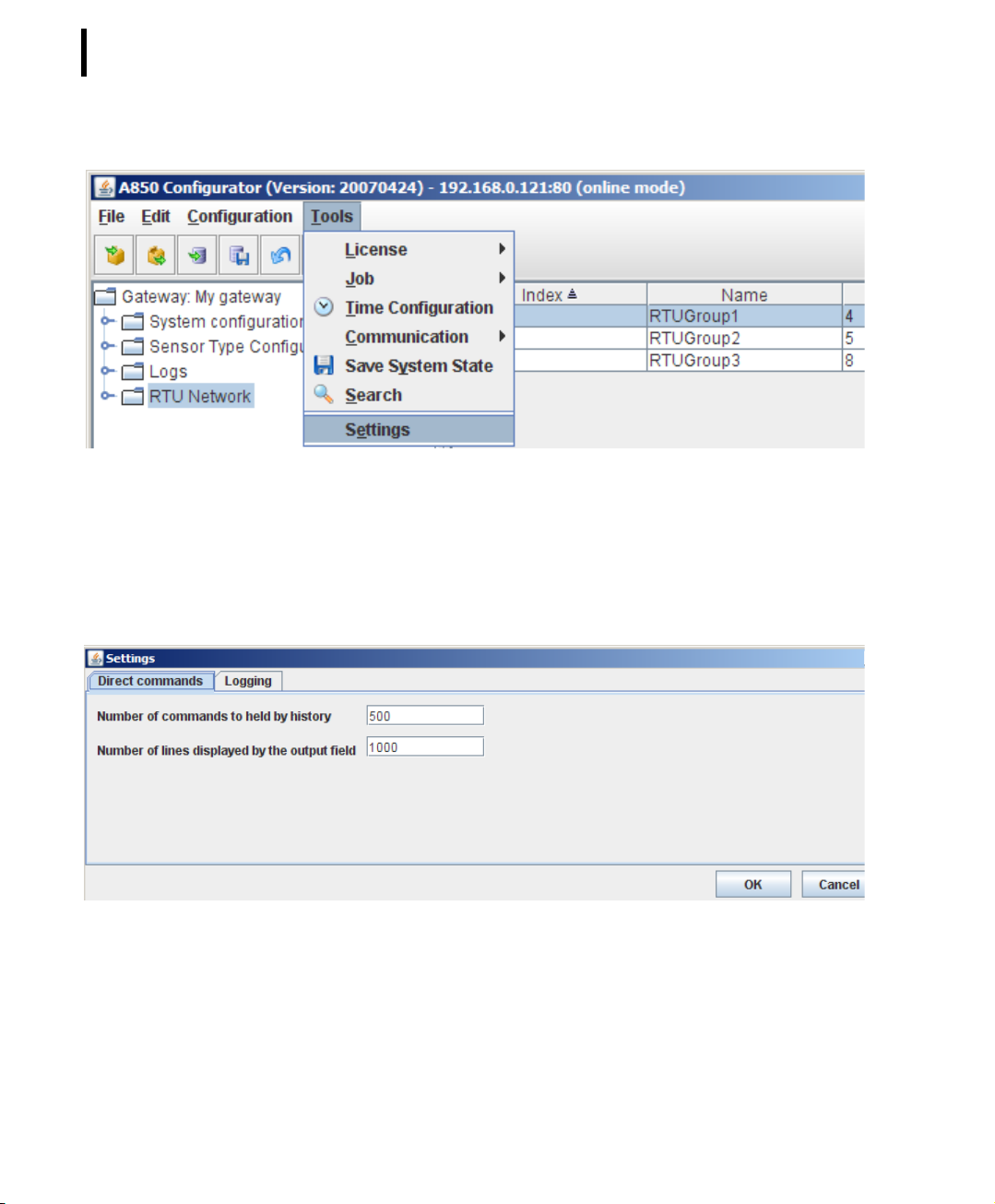
By the use of Settings, certain parameters determining the amount
of commands and loggings to be held in the GUI can be set up; as
soon as the limit of the specified amount is exceeded, an appropriate amount of the oldest saved information will be deleted.
Page 70
CHAPTER 2
70
System Setup
Figure 63. Settings Selection
"Settings” - “Direct commands" allows you to set up the number
of commands to be held by history (which is necessary to be able
to make use of the “Undo” command) and the number of lines displayed by the output field (for printing).
Figure 64. SettingsDirect Commands Window
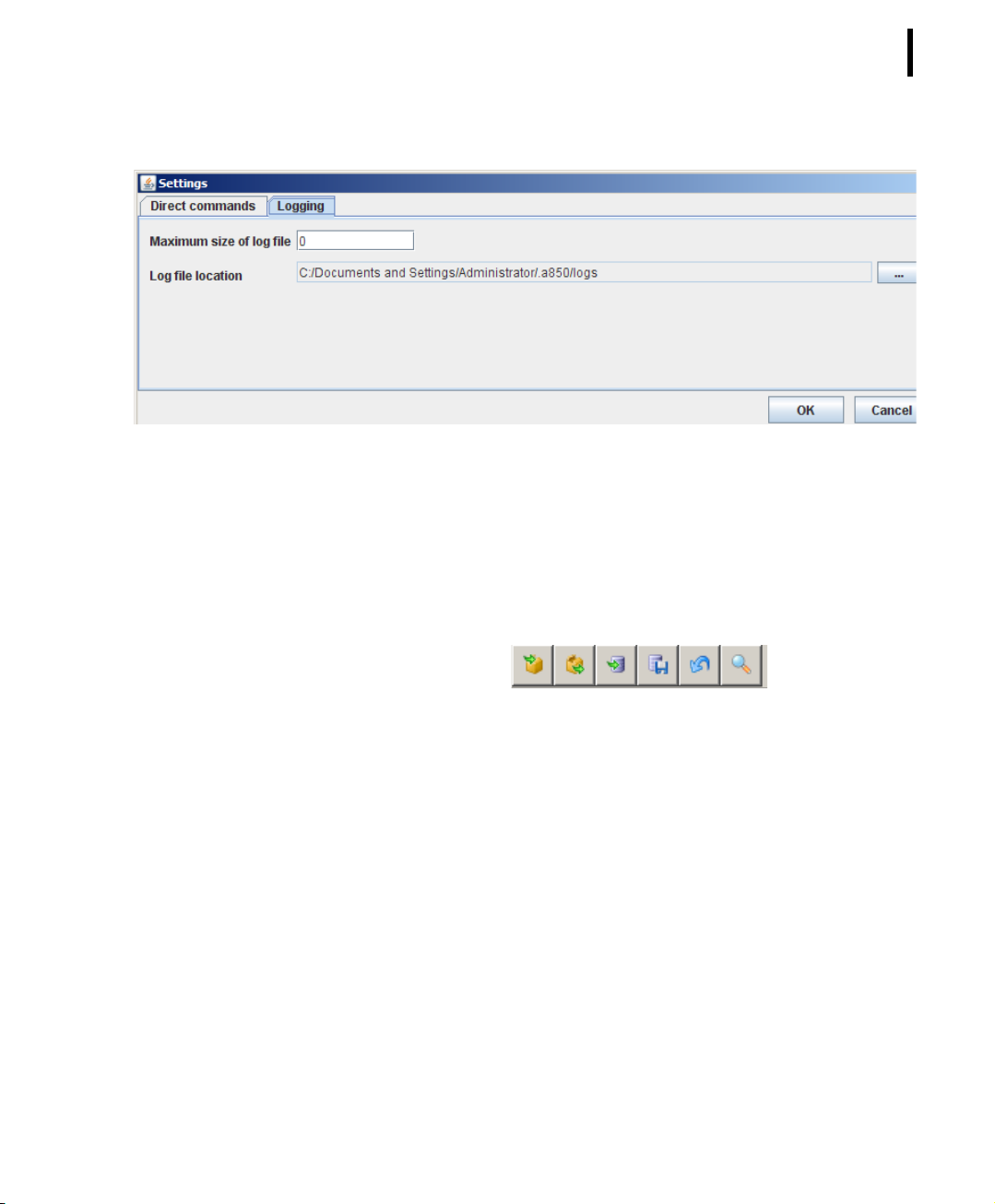
"Settings” - “Logging" allows you to define the maximum size of
the log file as well as the location where the log file will be stored.
If the character 0 is used as input variable for “maximum size”, the
size of the log file will be limited only by the storage capacity limitations of your PC.
Page 71
Commands on Tool Bar
Principles of GUI operation
Figure 65. SettingsLogging Window
CHAPTER 2
71
The main window of the Configuration User Interface has a configurable toolbar to shortcut menu selections.
Figure 66. Tool Bar
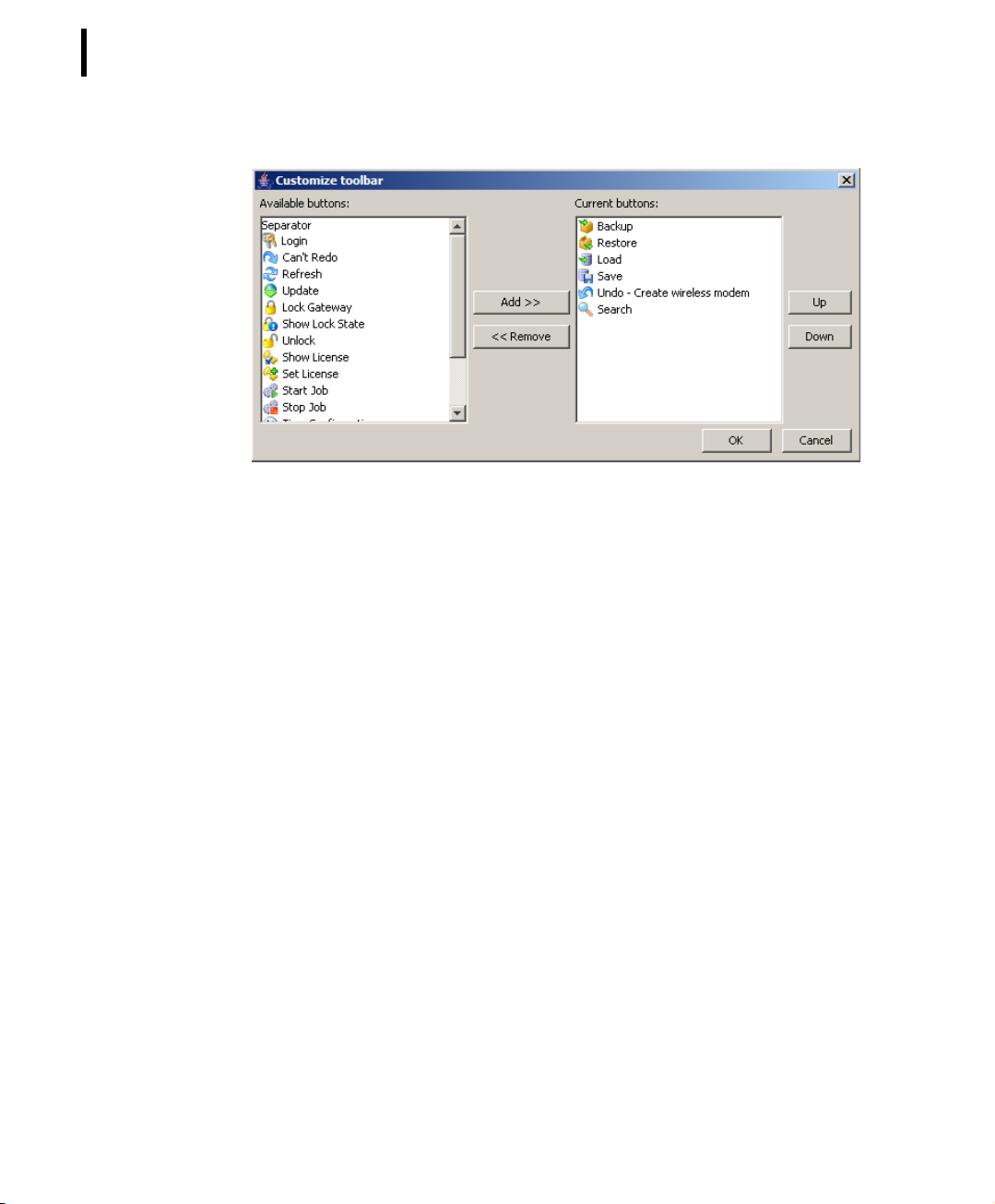
Each user can select his own subset of buttons to be shown out of
a predefined list of available toolbar buttons. The list of the buttons has an unchangeable predefined order.
The buttons are activated corresponding to the rights the user has
to perform the actions on the actual selected object(s) or class provided by the individual button.
Page 72
CHAPTER 2
72
System Setup
Figure 67. Customize Tool Bar
There are some predefined tool bar elements:
Backup
see ConfigurationBackup
Restore
see ConfigurationRestore
Load
see ConfigurationLoad
Save
see ConfigurationSave
Undo
see EditBackup
Search
see ToolsBackup
Page 73

Main Window views
CHAPTER 2
Principles of GUI operation
The main window of the A850 configuration GUI consists of the
following components:
• Tree view providing access to all the objects to be configured
of the actual configuration,
• Table view with a configurable column display to provide
sufficient information to identify the object to be worked on,
dependent on the selected node of the tree view,
• A menu bar including the menus to invoke the provided
functions,
• A tool bar providing shortcut access to specified functions,
• Context menus for the nodes of the tree view and for the
rows of the table view providing functions to be performed
on the underlying object.
From this main window, the user can start the navigation to either
detailed views of objects or to windows for issuing special functions or to the extended search interface for retrieving a limited
view of objects.
73
Tree view
The view in the left part of the main window shows the configuration data structured as tree to accelerate the navigation within it.
The nodes of the tree can either be mere structure constructs without configuration data (e.g. RTU groups) or objects with configuration data and containing multiple child objects (e.g., a RTU with
several sensors connected) or objects without further child objects
(e.g. sensors).
The tree view only contains objects which the actual user is permitted to see or to modify.
Page 74
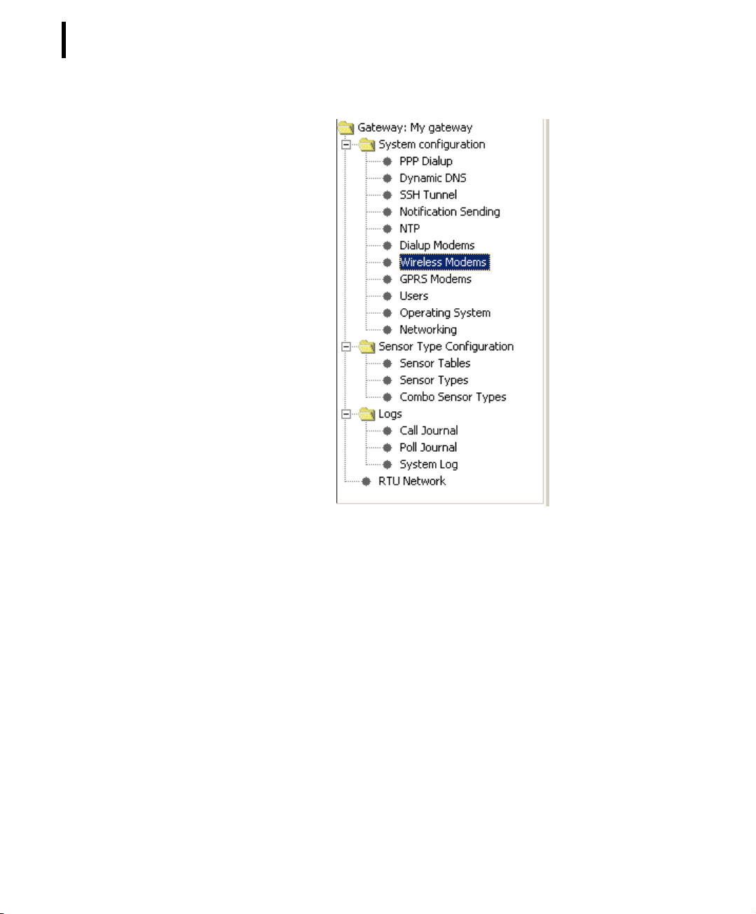
CHAPTER 2
74
System Setup
Figure 68. Tree view
Table view
The right part of the main window contains a table representation
of data.
The data shown depends on the selection of one or more nodes in
the tree view. The table view is a preview of the objects displayed
to support a quick selection of objects to be worked on.
A table can only contain objects of the same class.
Page 75
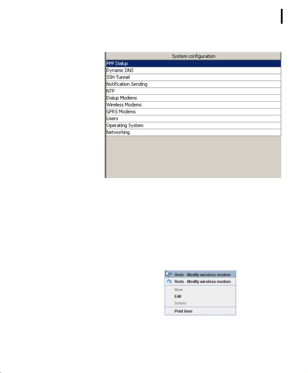
CHAPTER 2
Principles of GUI operation
75
Popup Context Menu
For each object represented as row in the table view or as node in
the tree view, a popup context menu can be activated by clicking
the right mouse button when the object is selected.
In the popup context menu, the commands applicable in each
case to the object or list entry, respectively, are provided.
Thereby, the following commands are always at your disposal:
Figure 69. Table view
Figure 70. Common Popup Context Menu
Page 76

CHAPTER 2
76
System Setup
Note: If you have the right to carry out changes at the A850, the
command “Edit” is available; otherwise, the command
“View” will be provided instead.
• Menu items “Undo” or “Redo” - initiate the “Undo” or
“Redo” function related to the undoable/redoable actions
with the selected object;
Note: The menu items “Undo” or “Redo” appear in each context
menu, depending on if one or both of these menu items is
or are applicable, respectively (see descriptions for “EditUndo” and “Edit-Redo”).
• Menu item “New” - open the detail window of the selected
object to define a new one;
• Menu item “Edit” - open the respective detail window and
display the attributes of the selected object for modification,
• Menu item “View” - open the respective detail window and
display the attributes of the selected object for inspection,
Note: The menu item “Edit” appears only if the user has been
granted appropriate access privileges for modifying the
selected object; otherwise, the menu item “View” will
always appear.
• Menu item “Delete” - delete the selected objects;
• Menu item “Print” - see a print preview of the details of the
selected objects in a formsheet processed for the printer and
start the printout on your default printer,.
Depending additionally from the object to be dealed with, accessory menu entries will be listed. As example, the popup context
menu for the object RTU is shown in the following figure:
Page 77
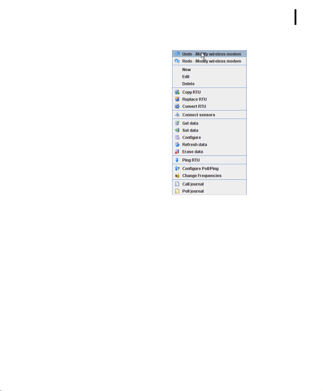
CHAPTER 2
Principles of GUI operation
77
Detail window
Figure 71. Extended Popup Context Menu for RTUs
For each class of configurable objects, a detail window provides
the detailed view on a specific object. It is used to enter the data
of a newly created object or to change the attributes of an existing
object.
A detail window of a class can be instantiated for each different
object. Trying to open a detail window of an already displayed
object results in activating the window with the selected object.
In each detail window, the buttons described consecutively are
available:
• Print - see a print preview of the details in a formsheet
processed for the printer and start the printout on your
default printer,
• OK - affirmation and acceptance of the entries made in the
respective detail window,
Page 78
CHAPTER 2
78
System Setup
Note: The OK button is only available if the right to enter or to
modify data has been granted and if data were really
entered or modified, respectively. In order to resume
entered or modified data, respectively, in the A850, the
command “Update” has to be performed consecutively, as
described in “ConfigurationUpdate”,
• Cancel - by “Cancel”, possible entries/modifications having
been made in the respective detail window are discarded, i.e.
the entries/modifications will not be resumed if the button
“Cancel” is clicked.
Figure 72. Detail Window Buttons
Web Interface
Home
Note: The Detail windows are described in the following chapters
“Configuring the Gateway” and “Using the Gateway”.
The web interface allows you to communicate with your A850 via a
web browser. The A850 provides the following web pages:
The web page “Home”, the front page of Adcon's Telemetry
Gateway A850, provides information about the device.
Page 79
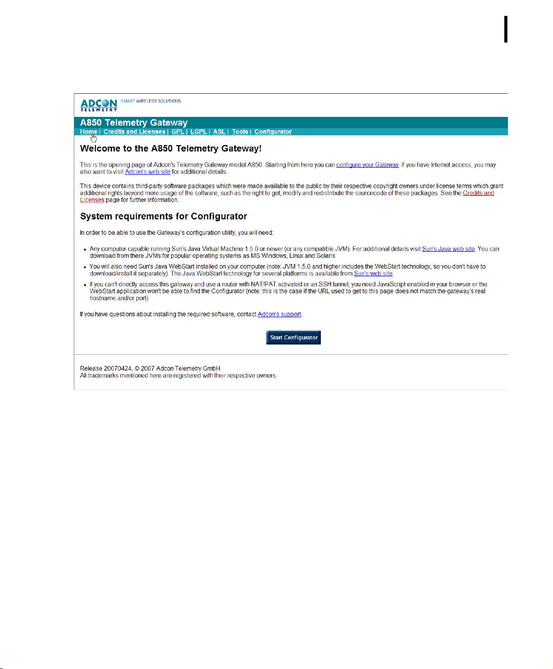
CHAPTER 2
Web Interface
79
Figure 73. Adcon’s A850 Home Page
The web page provides:
• The link “Configurator”, the hyperlink “configure your
Gateway” and the button “Start Configurator”, allowing you
to start the A850 GUI as described in chapter 3 and 4,
• “Adcon's web site”, a hyperlink forwarding you to the official
homepage of Adcon where you can retrieve other
information about Adcon products,
• “Sun's Java web site“ and “Sun's web site”, hyperlinks
forwarding you to the official homepage of SUN where you
can read up on the actual version of “Sun's Java Virtual
Machine” and download it if necessary,
• “Adcon's support”, a hyperlink forwarding you to your mail
client, allowing you to edit and send mail to the address
[email protected].
Page 80
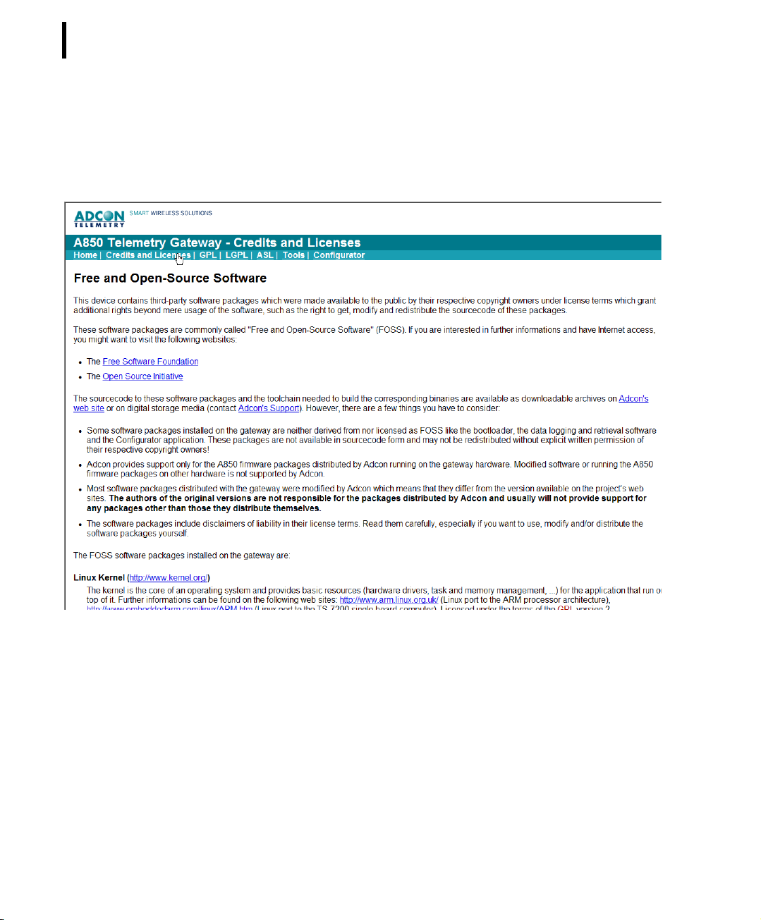
CHAPTER 2
80
System Setup
Credits and Licenses
In Credits and Licenses, the general license information forming
the basis of the software will be given to you:
GPL
Figure 74. A850 Credits and Licenses Web Page
The web page GPL shows you the GPL license information forming
the basis of the software:
Page 81
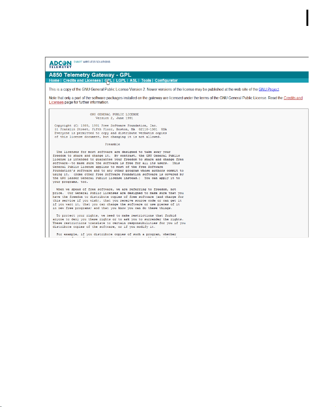
CHAPTER 2
Web Interface
81
LGPL
Figure 75. A850 GPL Web Page
The web page LGPL shows you the LGPL license information
underlying the software:
Page 82
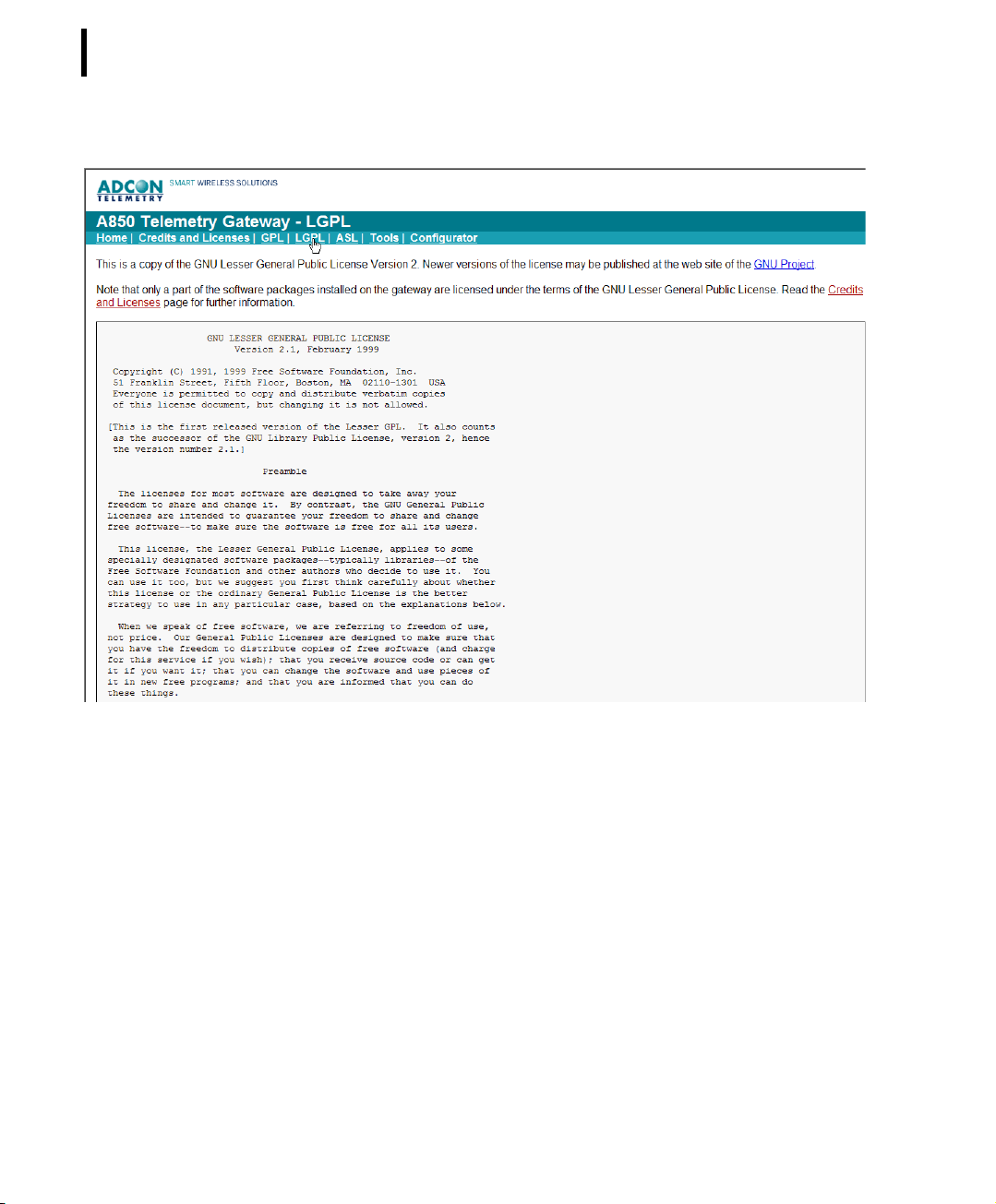
CHAPTER 2
82
System Setup
ASL
Figure 76. A850 LGPL Web Page
The web page ASL shows you the ASL license information forming
the basis of the software:
Page 83
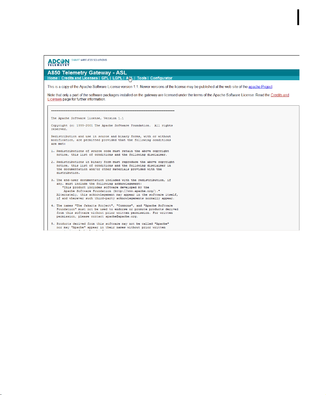
CHAPTER 2
Web Interface
83
Tools
Figure 77. A850 ASL Web Page
The web page “Tools” provides you support for debugging or for
using, respectively, your A850:
Page 84
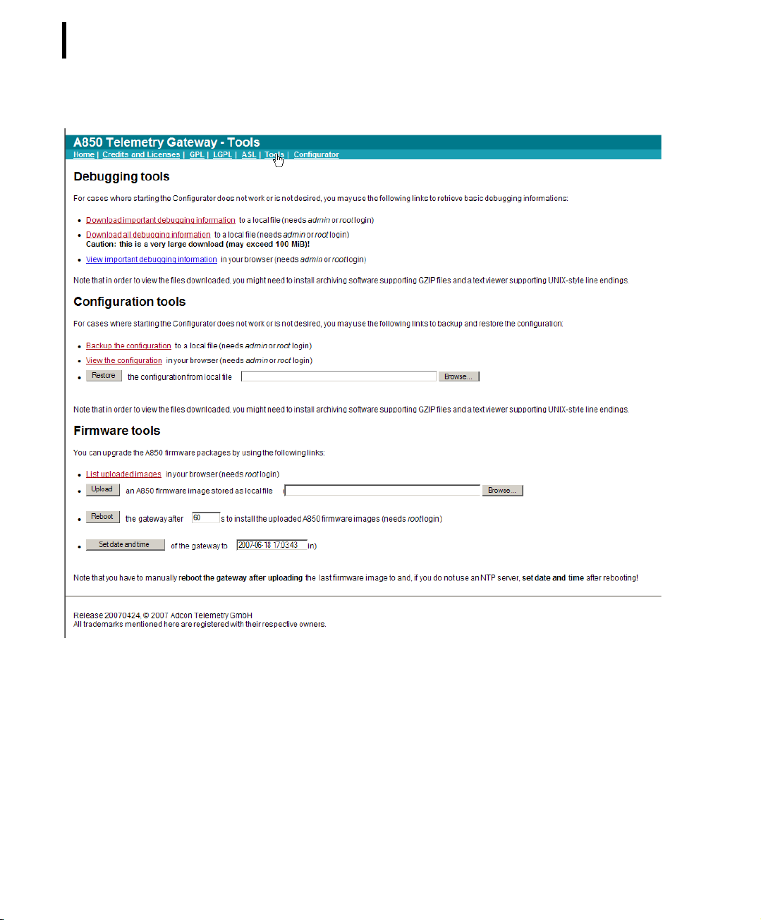
CHAPTER 2
84
System Setup
Figure 78. A850 Tools Web Page
This website offers to you access to
• Debugging tools,
• Configuration tools and
• Firmware tools.
Page 85

CHAPTER 2
Web Interface
Debugging tools
For cases where starting the Configurator does not work or is not
desired, you may use the following links to retrieve basic debugging information:
• “Download important debugging information to a local file”
allows you in case of possible problems to download the
most important information about the status of your A850 for
problem analysis to your PC and to save it in a local file,
• “Download all debugging information to a local file” allows
you in case of possible problems to download all available
information about the status of your A850 for problem
analysis to your PC and to save it in a local file,
• “View important debugging information” allows you in case
of possible problems to retrieve the most important
information about the status of your A850 and to get it
displayed via your web browser.
Note: In order to be able to use the “Debugging tools”, you have
to login as system administrator (user “root”) or as user
administrator (user “admin”).
85
Configuration tools
For cases where starting the Configurator does not work or is not
desired, you may use the following links to backup and restore the
configuration:
• “Backup the configuration to a local file”: the command
“Backup” allows you to save the data from the A850 locally
on your PC, giving you the opportunity to replay these data
later again into the A850 by the command “Restore” which
allows you to reestablish the state stored by “Backup”(see
ConfigurationBackup);
• “View the configuration in your browser”: view a XML-based
information of the actual configuration of the A850;
• “Restore the configuration from local file”: the command
“Restore” allows you to reload data from the A850 saved by
the command “Backup” on your PC again into the A850 if
you want to reestablish a certain state of the A850 (see
ConfigurationRestore);
Page 86

CHAPTER 2
86
System Setup
Note: In order to be granted the rights to use the configuration
tools, you must have logged in as system administrator (user
“root”) or as user administrator (user “admin”).
Firmware tools
Firmware tools are provided for your support when performing
firmware upgrades which may become available in the future. As
soon as an upgrade of the firmware will be available, you will be
able to download it from Adcon’s website, following the instructions given there, or by receiving it from your Adcon distributor,
respectively. After having the new firmware available on your local
PC, you will have to transfer it to your A850.
The following firmware tools are provided:
• “List uploaded images in your browser”: view all uploaded
firmware images stored in the flash memory of your A850,
Note: The purpose of this feature is to provide the possibility to
check if all files required for a firmware upgrade have been
uploaded to the A850. This check should be made before
the new firmware is started with “reboot”, after that, the list
of uploaded images will be erased again.
• “Upload an A850 firmware image stored as local file”: load an
actual version of the firmware image in your A850,
Note: Perform an upgrade only if you have problems with your
A850 or if an upgrade is recommended by Adcon, respectively.
• “Reboot the Gateway”: after a firmware upgrade has been
prepared, you have to reboot your A850 anew in order to
activate the new firmware.
• “Set Date and Time of the Gateway”: in any case, after a
firmware upgrade, you have to enter date and time anew.
Note: In order to be granted the rights to use the firmware tools,
you must have logged in as system administrator (user
“root”).
Page 87

Chapter 3. Configuring the Gateway
The configuration of the Gateway summarizes all administrative
settings required for its use and is therefore to be entrusted only
to skilled users qualified as system administrators. According to
this, only the user “root” (the system administrator) has the rights
to make all the settings for configuring the Gateway. As a basic
principle, all other users have only the right to view the settings,
but not to make any changes. The only exception to this rule is
coupled with the point “Users” in the tree window (see below) as
this functionality gives other user groups a limited capability to
make some settings of the configuration. This feature will be
described in detail in chapter 4, “Using the Gateway”.
CHAPTER 3
87
In order to configure the Gateway, you have to proceed as follows:
• Login as system administrator (user “root”) as already
explained in chapter 2, “Connecting to the GUI” (Fig. 13,
“Login”). After the login, the main window of the A850
Configurator (Fig. 14) appears.
• Lock the Gateway by “Lock Gateway” as already explained in
chapter 2, “Commands on the Menu Bar”, Figs. 23 - 25. This
is necessary by reason of the multi-user-capability of the
Gateway, in order to prevent other users from attempting any
conflicting activities while the Gateway is configured.
• Open the “System configuration” in the “Tree view” by
double clicking. Now, the main window of the A850
Configurator as displayed below in Fig. 79 will appear.
The procedure of configuring the Gateway is considerably facilitated by the user-friendly GUI. As you will notify, the status line of
the window will show the user having logged in as well as the
remaining time the Gateway will stay locked yet.
Page 88
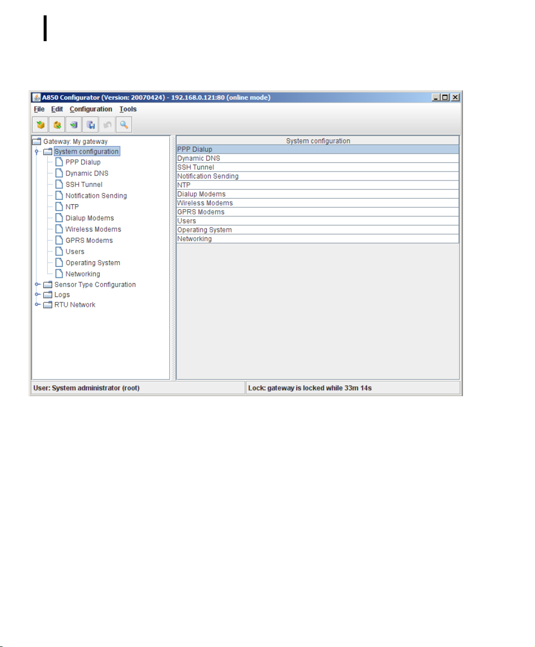
CHAPTER 3
88
Configuring the Gateway
Figure 79. System Configuration List Window
The left part of the system configuration list shows the tree structure (“Tree view”) of the system configuration while the right part
displays the respective corresponding table (“Table view”) of the
marked item. The settings required for configuring the Gateway
are summarized in the tree window in the folder named “System
configuration”. The topmost folder named “Gateway: My Gateway” contains some basic information about the Gateway itself
which will be discussed at the end of this chapter.
The system configuration list window shows you the items to be
configured as well in its left part as in a “Tree view” as in its right
part in “Table view”.
Page 89

CHAPTER 3
The system configuration settings encompass:
• PPP (Point-to-Point Protocol) Dialup - management of the PPP
internet connection,
• Dynamic DNS (Domain Name System) - management of your
host name in the DNS to convert host names into affiliated IP
(Internet Protocol) addresses in cases where the IP address is
not static,
• SSH (Secure Shell) Tunnel - management of Secure Shell
Tunnelling to connect terminal devices via internet and by
secure communication,
• Notification Sending - management of the allocation of
recipients for transmissions of messages related to specific
events,
• NTP - management of the Network Time Protocol (a protocol
for time synchronization between computers),
• Dialup Modems - management of dialup modem
communications with their RTUs,
• Wireless Modems - management of Wireless Modem
communications with their RTUs,
• GPRS Modems - management of GPRS modem
communications with their RTUs,
• Users - management of users and user groups as well as of
their respective access rights,
• Operating System - management of operating system
specific assignments,
• Networking - management of the network configuration,
• Gateway Detail - management of Gateway specific
information.
89
PPP Dialup
With PPP Dialup, a network connection to the internet or to a PPP
server, respectively, is established by means of a dialup modem.
The concerned menu allows you to determine the configuration of
a PPP network for a dialup modem connection.
Note: In order to be able to use the PPP network, you have to
enable at least one of your dialup modems for PPP dialup
(“allow PPP dialup”).
Page 90
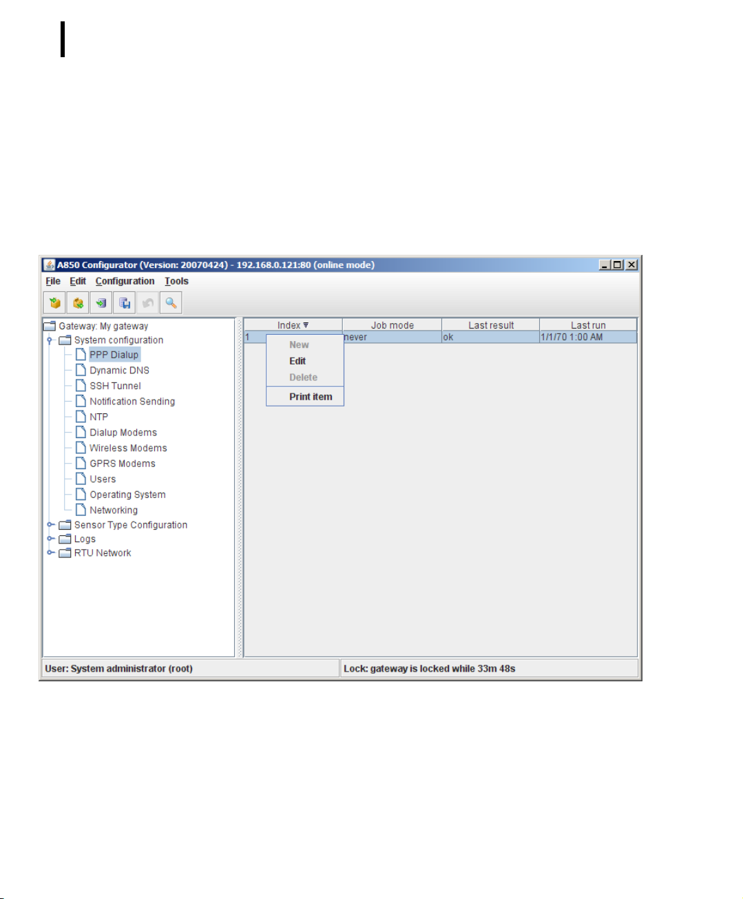
CHAPTER 3
90
Configuring the Gateway
The A850 supports two dial-up peer configurations: a primary
which is tried first and a secondary which is only used if the primary
connection can't be established. A secondary configuration is not
required as a matter of principle, but as it enhances the redundancy of your network, it is recommended to make use of this
practical feature.
Note: Points which require execution of a login script are not sup-
ported.
Figure 80. PPP Dialup Selection
Via the context menu for PPP Dialup, you can
• lay down the PPP Dialup configuration by “Edit”,
• see a print preview of the selected PPP Dialup configuration in
a formsheet processed for the printer and start the print on
your default printer by “Print item”.
Page 91

CHAPTER 3
Note: The greyed-out choices “New” and “Delete” are not avail-
able in this context. The choice “Edit” ist only available if
the Gateway is locked while “View” is only available if the
Gateway is unlocked.
Note: Menu items “Undo” or “Redo”: see “Popup Context Menu”
in chapter 2.
Double-clicking the PPP Dialup selected in the “Table view” allows
you to check the selected PPP Dialup configuration.
Note: If not otherwise stated explicitly, the action performed in a
screenshot containing a context menu like the one depicted
in Fig. 80 will always be a click on “Edit”, and the screenshot
displayed as the next will always be the one illustrating the
situation resulting from this action, regardless of any peculiar properties of the window appearing next (e.g. replacing
the previous window or just appearing in addition to it as a
“pop-up window”).
91
Note: For being able to use PPP Dialup, it is necessary to make a
PPP Dialup setup on at least one Dialup Modem.
Page 92
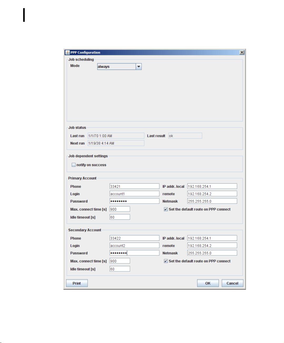
CHAPTER 3
92
Configuring the Gateway
Figure 81. PPP Configuration Window
Page 93
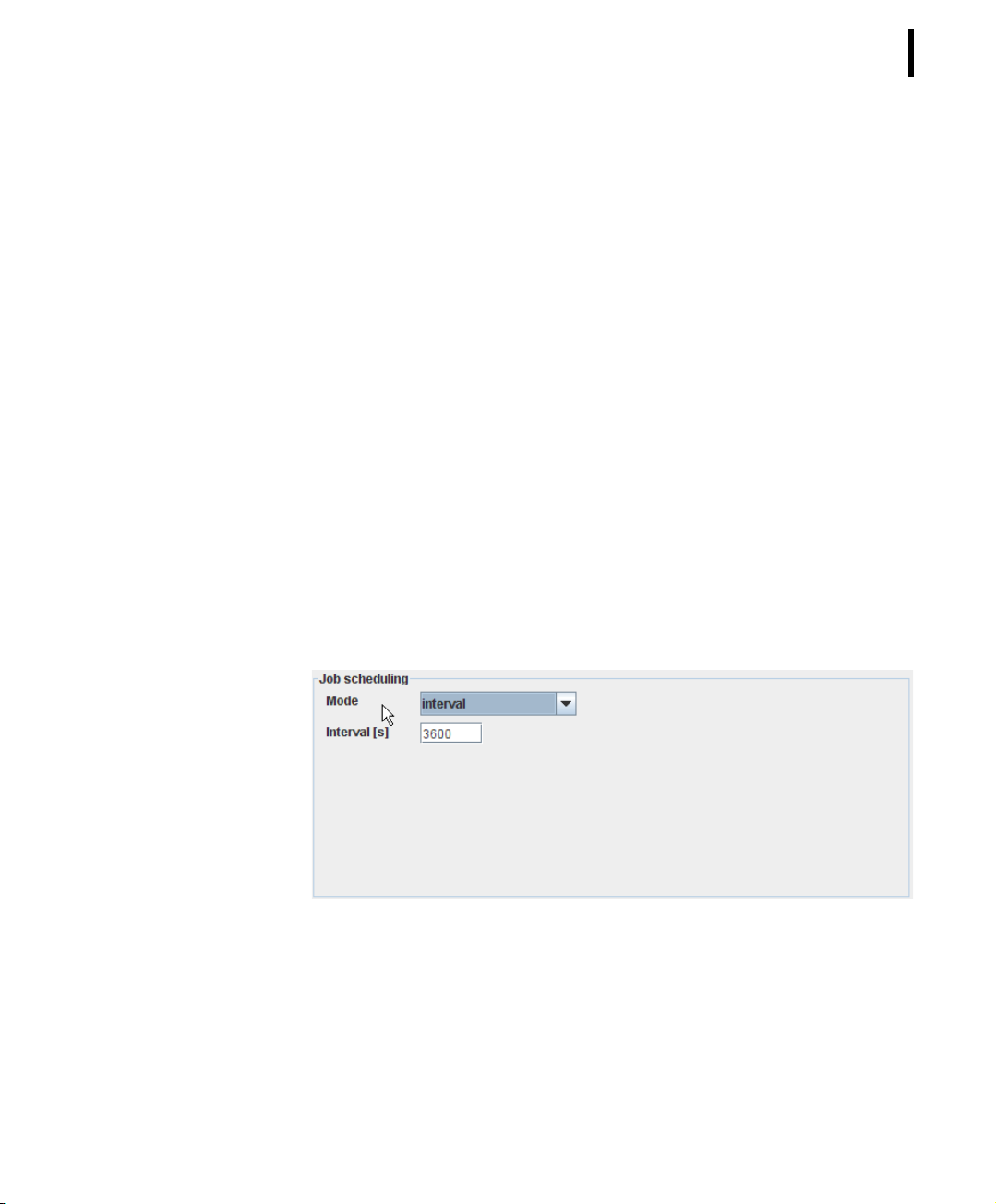
CHAPTER 3
The following window areas are provided in the window “PPP
Configuration”:
• Job scheduling: allows to define a time schedule (“Mode”) to
determine when the A850 has to establish a PPP connection
to the internet;
• Job status: allows to get the information when the last PPP
connection attempt was made, with which success it was
performed, and when the next attempt to connect to the
internet is scheduled;
• Job dependent settings: allow to lay down that a message
will be forwarded to the address entered into the tree window
“Notification Sending” in case of a successful set-up of a
connection with the internet;
• Primary Account: allows to set up the access data of the
primary account;
• Secondary Account: allows to set up the access data of the
secondary account.
93
Job scheduling
Figure 82. PPP Configuration - Job scheduling
Within “Job scheduling”, the pull down menu “Mode” provides
the following set-ups to gather contact with the internet:
Page 94
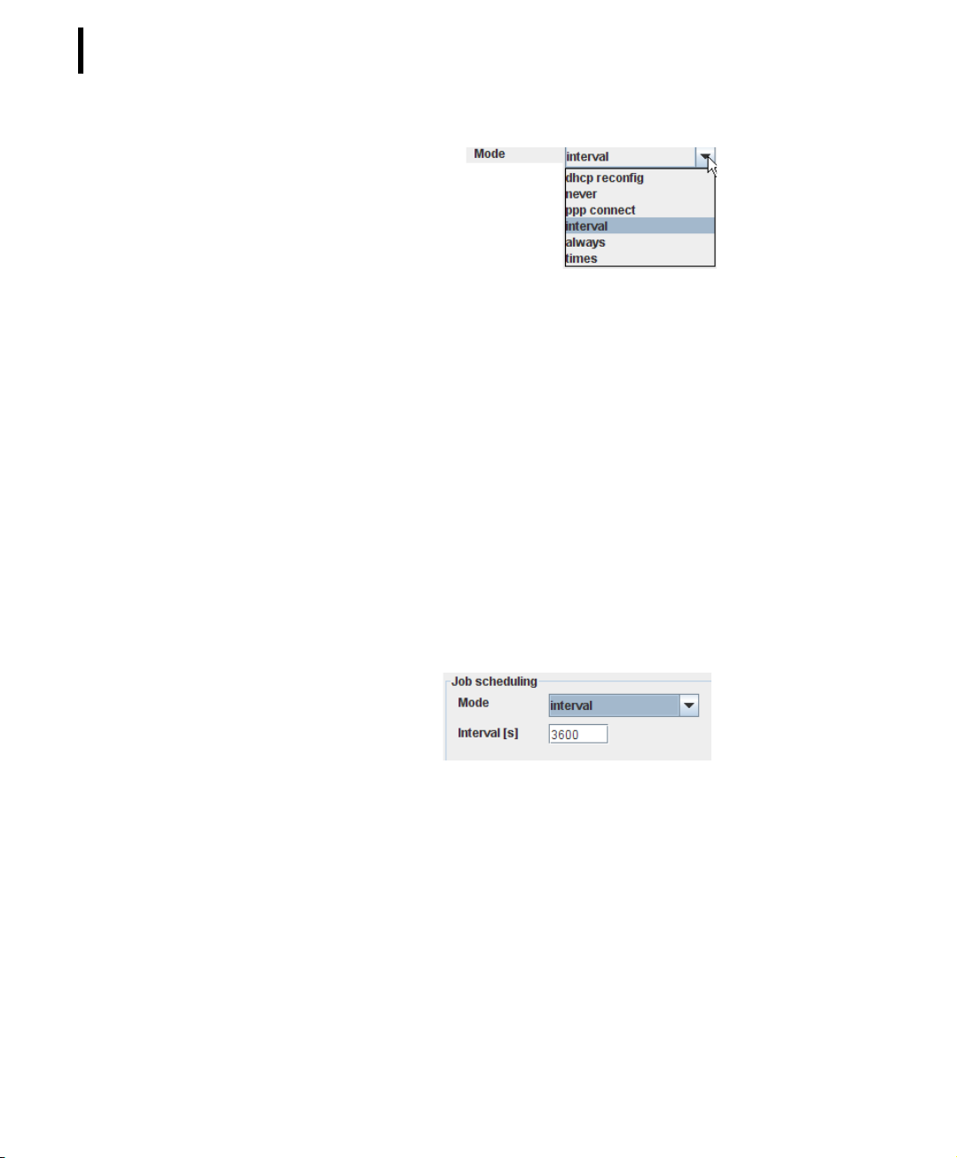
CHAPTER 3
94
Configuring the Gateway
Figure 83. PPP Configuration - Job scheduling - Mode
Note: The job scheduling layed down can be oversteered by the
commands ”Start Job” or “Stop Job” according to Fig. 43
or 46, respectively.
• Mode - in this combo box, the time of establishment of a PPP
connection is determined, featuring the following selections:
• dhcp reconfig - to re-establish your former dhcp settings
after having changed them in the tree window
“Networking”;
• never - to prevent an PPP connection to be established
automatically;
• ppp connect - to force a PPP connection to be
established automatically;
• interval - to force a PPP connection to be established at
certain regular intervals (the interval in seconds has to be
put into the field “Interval [s]”):
Figure 84. PPP Configuration - Job scheduling - Mode - Interval
• always - to force an internet connection to be always
established;
Page 95
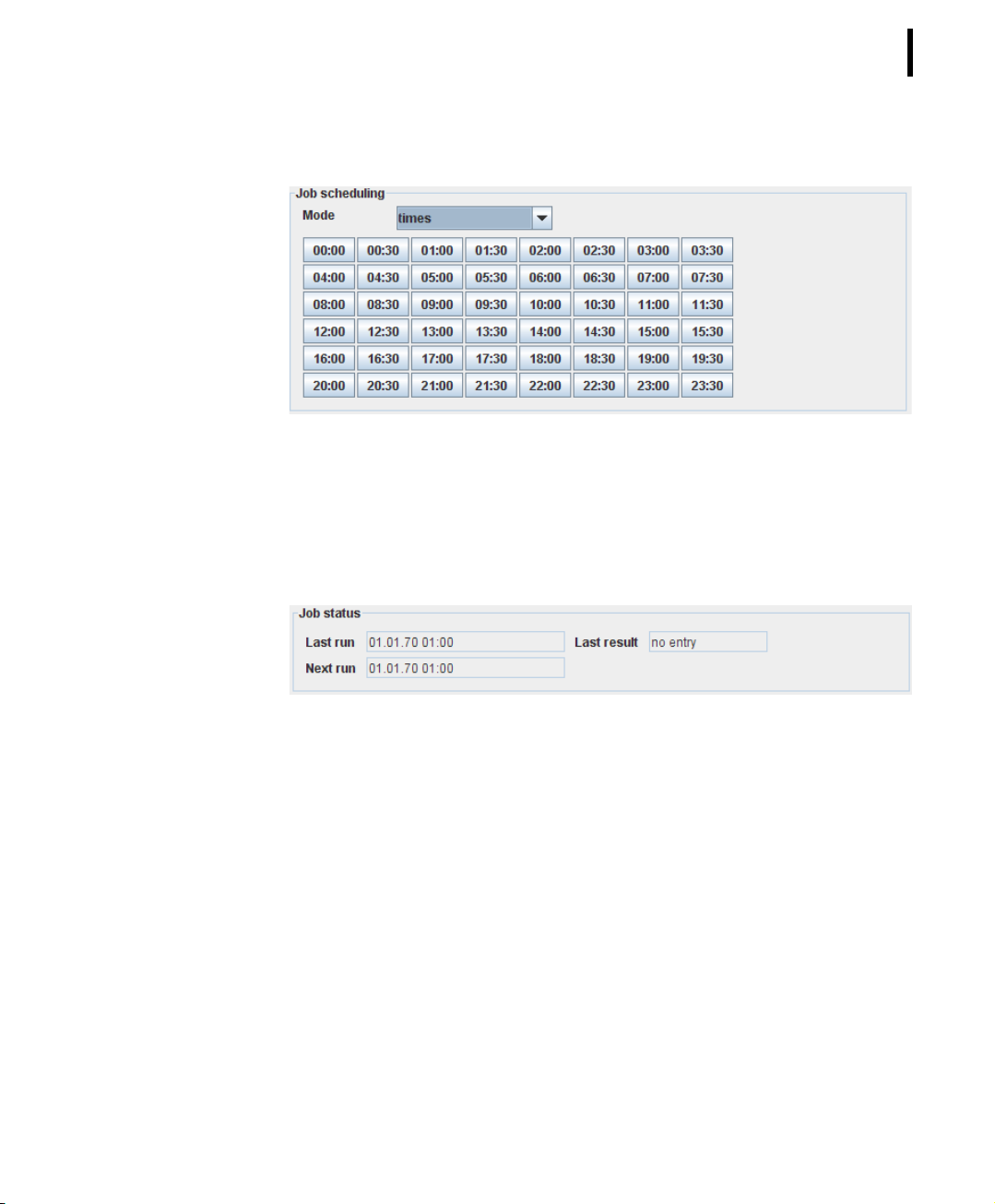
CHAPTER 3
• times - to force an internet connection to be etablished
at specific times:
Figure 85. PPP Configuration - Job scheduling - Mode - Times
Job status
“Job status” allows you to check the time and the result of the last
PPP network connection set-up:.
95
Figure 86. PPP Configuration - Job status
• Last run - displays the time of the last PPP network connection
set-up;
• Last result - displays the result of the last connection set-up;
• Next run - displays the time of the next planned connection
set-up with the PPP network.
Job dependent settings
Allow you to determine that, in case of successful connection to
the internet, a message has to be forwarded to the address
enlisted in the tree window “Notification Sending”.
Page 96
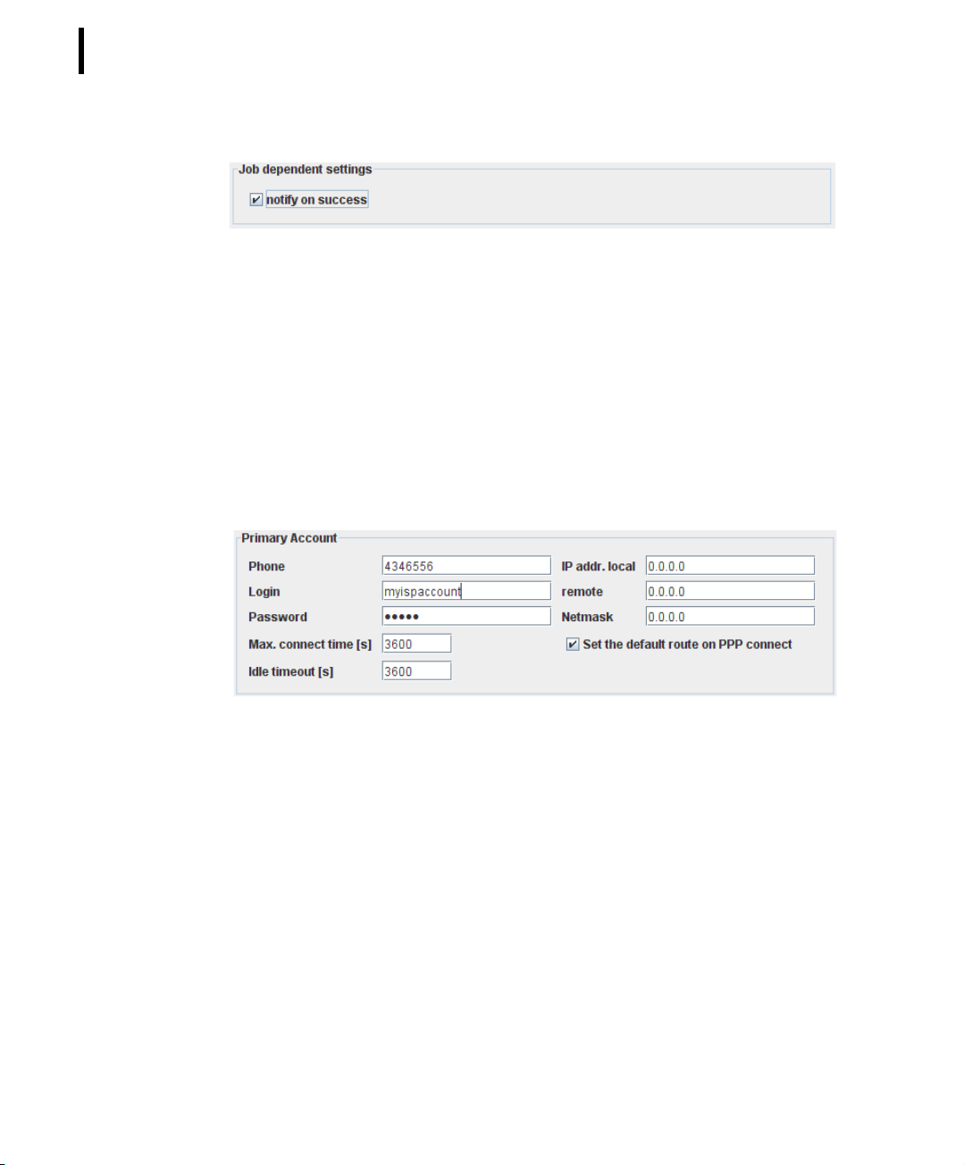
CHAPTER 3
96
Configuring the Gateway
Figure 87. PPP Configuration - Job dependent settings
• notify on success - if the checkbox “notify on success” is
marked, a “PPP network connection success message” will be
sent in case of successful connection.
Primary Account
Allows you to enter the following access data to your ISP or PPP
server for the Primary Account:
Figure 88. PPP Configuration - Primary Account
• Phone - enter the phone number provided by your ISP or PPP
serverfor dialup connection;
• Login - enter the account name provided by your ISP or PPP
server for the login;
• Password - enter the password provided by your ISP or PPP
server;
• Max. connect time [s] - allows you to determine the maximum
time a connection to your ISP or PPP server shall be allowed
to persist; if you enter the digit 0, the connection will persist
as long as it will be interrupted either by the defined “Job
scheduling” or by manual termination by the command “Stop
job”;
Page 97
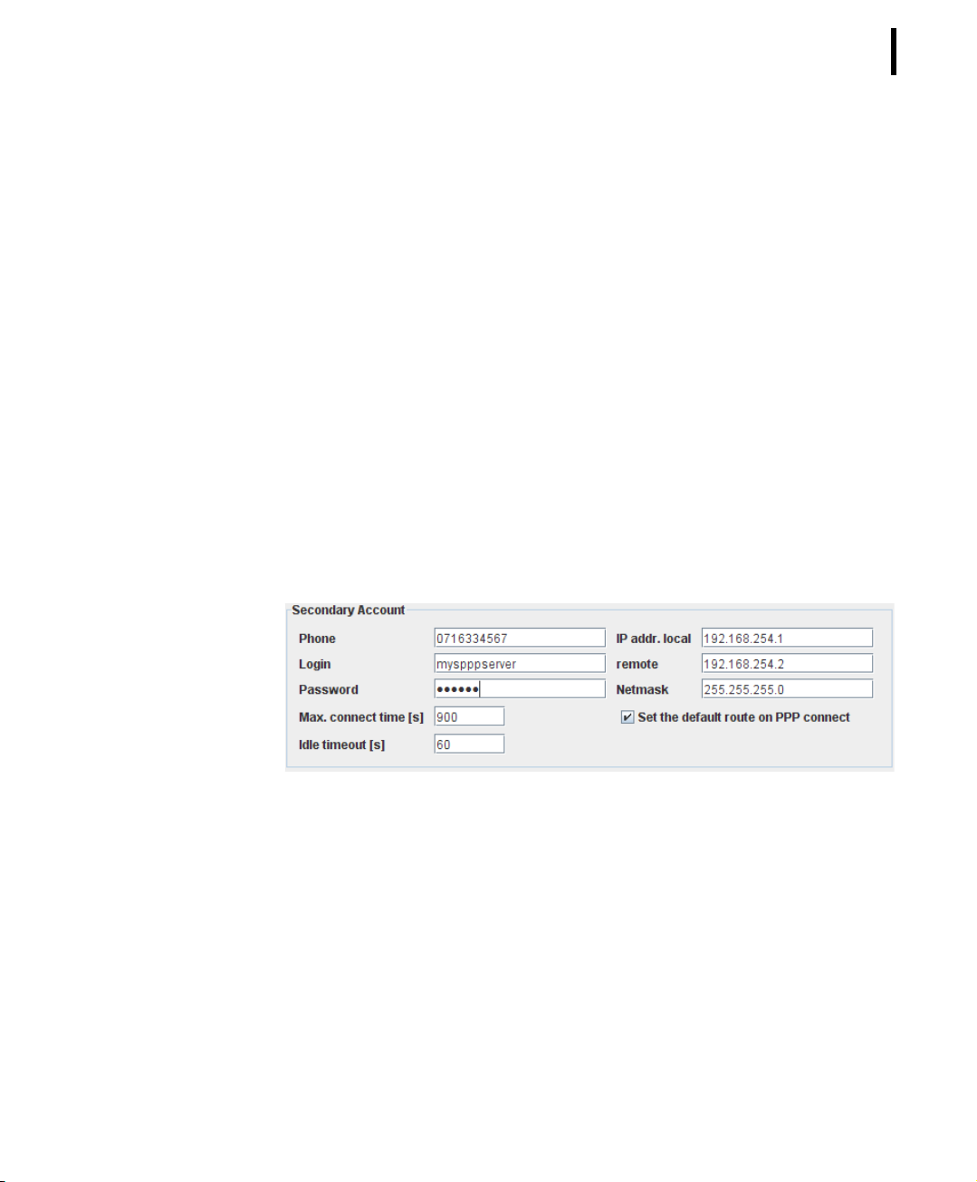
CHAPTER 3
• Idle timeout [s] - allows you to determine after which period
of inactivity the connection to your ISP or PPP server shall be
terminated;
• IP addr. local - allows you to enter a local IP address for your
PPP connection;
• remote - allows you to enter a remote IP address for your PPP
connection;
• Netmask - requires the masking of the IP address;
Note: If your ISP or PPP server assigns dynamic IP addresses, you
have to enter “0.0.0.0” in the fields “IP addr. local”,
“remote” and “Netmask”.
• Set the default route on PPP connect - if the checkbox is
marked, the opposing communications device is used as a
router when the PPP connection is established.
Secondary Account
97
Figure 89. PPP Configuration - Secondary Account
A secondary account is an alternative account for an internet or
PPP server connection which will be used if no internet connection
comes about through the primary account. The secondary account
can be either an independent access to an ISP or only represent
another dialup phone number for the ISP of the primary account.
Note: A secondary account for an internet connection is a matter
of redundancy and as such, not necessary on principle.
Page 98

CHAPTER 3
98
Configuring the Gateway
Dynamic DNS
Dynamic DNS (Domain Name System) means that your A850 will
be accessible in the internet by a host name. This is important if
your ISP provides only dynamic IP addresses, i.e. IP addresses
which can always change with each login into the internet.
Dynamic DNS allows you to assign a fixed host name to a dynamic
IP address and to access this address through the host name.
The dynamic DNS updates enables other hosts on the internet to
connect to the A850, as long as the following preconditions are
met:
• If the A850 is directly connected to the ISP, it must get an
official static or dynamic IP address assigned by the ISP;
• If the A850 is acting behind a NAT (Network Address
Translation) router, the NAT router must get an official static
IP address assigned by the ISP;
Note: For cases where the A850 is acting behind a NAT router
which gets a dynamic ISP address assigned by the ISP,
dynamic DNS updates should be supported by and enabled
on the router.
• If there is a transparent firewall between the A850 and the
internet, it must allow certain incoming TCP/IP connection
types (HTTP or HTTPS as a minimum);
• The user must create an account on a supported dynamic
DNS service.
The A850 supports two dynamic DNS update servers: a primary
which is tried first and a secondary which is only used if the primary
connection can't be established. The A850 supports updating its IP
address on a selection of the following dynamic DNS services:
• dyndns, http://www.dyndns.org/
• eurodyndns, http://www.eurodyndns.org/
• hn, http://www.hn.org/
• no-ip, http://www.no-ip.com/
• ods, http://www.ods.org/
• ovh, http://www.ovh.com/
• regsh, http://www.regsh.com/
Page 99
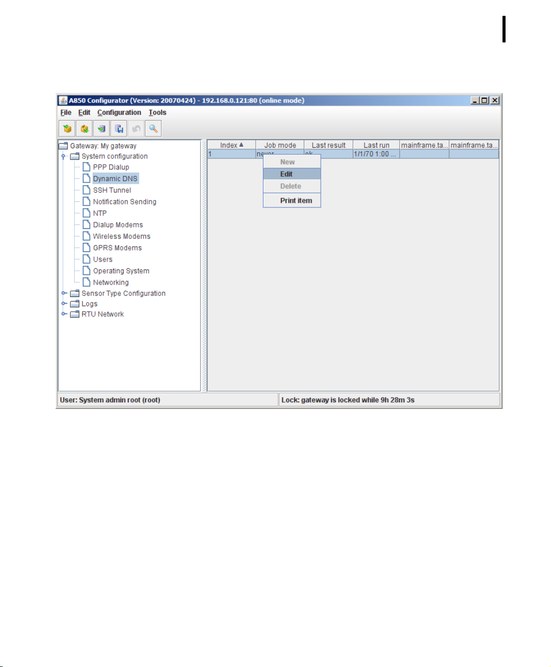
CHAPTER 3
99
Figure 90. Dynamic DNS Selection
The context menu for Dynamic DNS gives you the following
options:
• “Edit” - to define the Dynamic DNS Update configuration;
• “Print item” - to display the defined Dynamic DNS Update
configuration in a form formatted for the printer which can be
printed from there on your default printer.
Note: The greyed-out choices “New” and “Delete” are not avail-
able in this context.
Note: Menu items “Undo” or “Redo”: see “Popup Context Menu”
in chapter 2.
Page 100
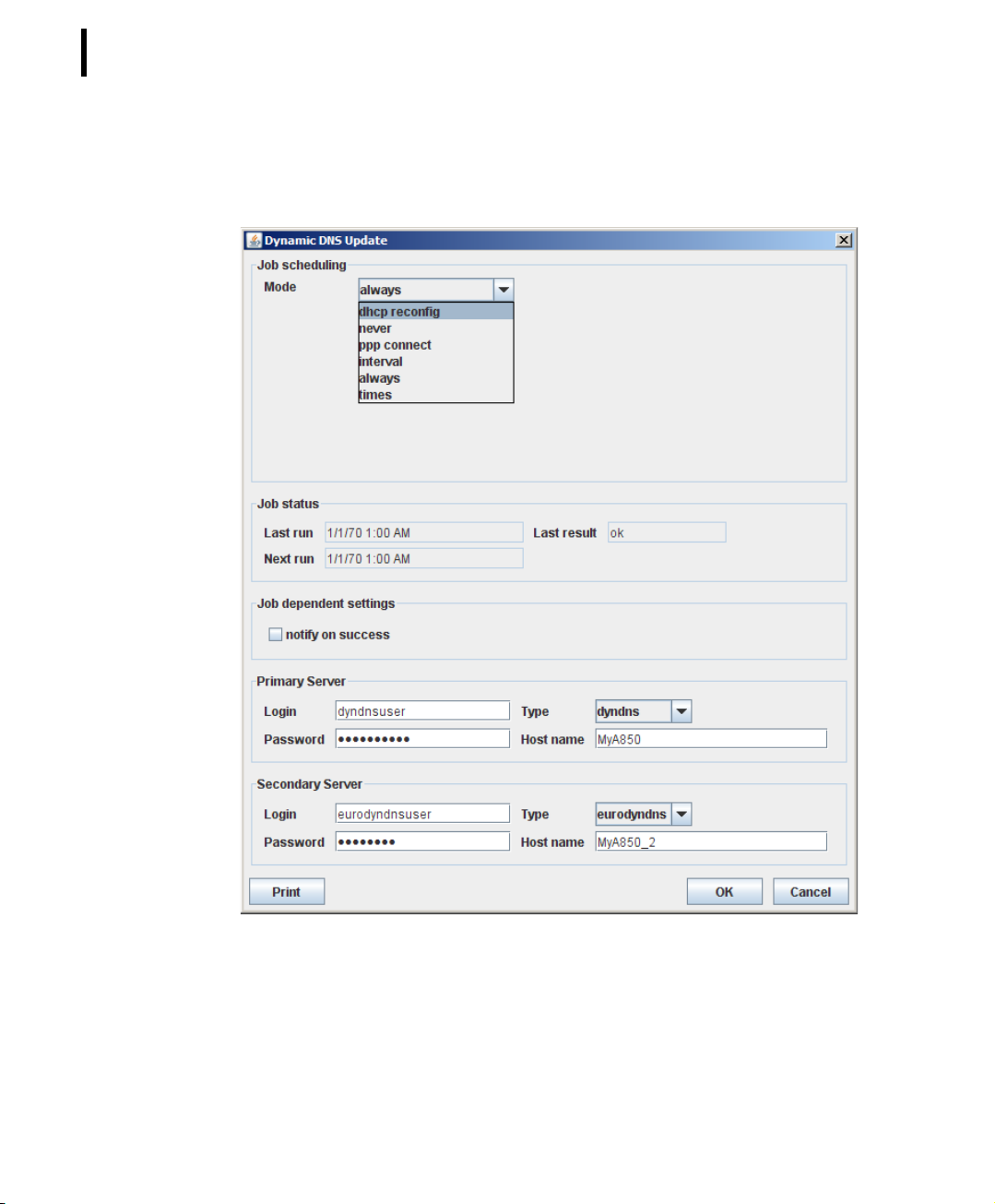
CHAPTER 3
100
Configuring the Gateway
Double-clicking the Dynamic DNS selected in the "Table view"
allows you to check the selected Dynamic DNS configuration.
Figure 91. Dynamic DNS Update Window
The window “Dynamic DNS Update” provides the following window areas:
 Loading...