

Page 1

ADCON
TELEMETRY
addIT A720/A723 Series
User Guide
SMART WIRELESS SOLUTIONS
Page 2

ADCON
TELEMETRY
ADCON TELEMETRY GMBH
INKUSTRASSE 24
A-3400 KLOSTERNEUBURG
AUSTRIA
TEL: +43 (2243) 38 280-0
FAX: +43 (2243) 38 280-6
http://www.adcon.at
Proprietary Notice:
The Adcon logo, the A720 and A730 series, addIT™, the A840 series, addVANTAGE®, addVANTAGE Lite and addVANTAGE Pro are trademarks or registered trademarks of Adcon Telemetry.
All other registered names used throughout this publication are trademarks of their respective
owners.
Neither the whole nor any part of the information contained in this publication may be reproduced in any material form except with the prior written permission of Adcon Telemetry.
This publication is intended only to assist the reader in the use of the product. Adcon Telemetry
shall not be liable for any loss or damage arising from the use of any information in this publication, or any error or omission in such information, or any incorrect use of the product.
Document Release 2.0, August 2000
Copyright ©1999-2004 by Adcon Telemetry GmbH.
All rights reserved.
Page 3

Contents
3
Contents ______________________________________________ 3
Chapter 1. Introduction _________________________________ 5
What are addIT devices?_________________________________5
Installation issues _______________________________________6
Conventions____________________________________________7
Chapter 2. Using the Base Station _______________________ 9
Opening the packages___________________________________9
Installing the base station _______________________________10
Installing the receiver ________________________________10
Installing the power supply ___________________________11
Replacing the fuse___________________________________12
Configuring the software_____________________________12
Chapter 3. Using the RTU ______________________________13
Opening the packages__________________________________13
Page 4

4
Contents
Installing the RTU _____________________________________ 14
More about the LED tool ____________________________ 16
Configuring an addIT RTU in the addVANTAGE software 17
Maintaining and servicing the RTU_______________________ 17
The RTU battery____________________________________ 17
Changing the battery _______________________________ 18
Chapter 4. Performing Advanced Functions_____________ 21
Device series _________________________________________ 22
Understanding connectors______________________________ 22
The receiver connector______________________________ 22
The RTU connectors ________________________________ 23
Configuring the devices________________________________ 24
Serial communication protocol __________________________ 25
General format of a command _______________________ 25
General format of an answer _________________________ 25
Using terminal commands ______________________________ 26
Series 1 devices ____________________________________ 26
The SET series of commands______________________ 26
Querying the actual configuration parameters_______ 29
Series 2 and 3 devices ______________________________ 30
Notifications __________________________________________ 53
Returned errors list ____________________________________ 54
Command line interpreter ___________________________ 54
Device descriptors and storage handler _______________ 54
Real time clock_____________________________________ 54
Radio interface _____________________________________ 54
Notifications _______________________________________ 55
Appendix. Specifications ______________________________ 57
Index ________________________________________________ 61
Credits and Colophon_________________________________ 65
Page 5

Chapter 1. Introduction
5
This manual explains the hardware aspects of Adcon’s addIT™
A72xx series, including installation issues and certain parameter
configurations. The manual is divided into these chapters:
• "Introduction," which gives some general information and
document conventions.
• "Using the Base Station," which details the installation and
use of the receiving unit.
• "Using the RTU," which details the installation and use of the
remote telemetry unit.
• "Performing Advanced Functions," which discusses technical
information for the advanced user.
What are addIT devices?
Adcon’s addIT devices (A720, A723 and A720B) are uniquely
suited to your remote measuring needs. The A720 and A723
devices are remote telemetry units (RTU) that can be used with
Adcon and other compatible sensors to track those parameters
important to you. And the A720B device, in conjunction with your
computer, is a base station that offers many ways for you to view
and manipulate the data received from the RTUs.
Page 6

CHAPTER 1
6
Introduction
Installation issues
The addIT A720/A723 RTU can be used in one of the following
ways:
• Installed in the vicinity of an Adcon remote measuring station
(A730MD), the addIT RTU can use the A730MD station to
relay its data to a base station (A730SD or A840). If the base
station is close enough to the addIT RTU, the RTU can
communicate directly with the base station.
• As a standalone device, the addIT RTU communicates directly
with the addIT base station (A720B).
The addIT A720B base station works with up to three addIT RTUs,
storing the data it receives until you download it to your computer.
The following restrictions apply:
• In general, the maximum “line-of sight” distance an addIT
RTU can communicate is 800 m (approximately half a mile).
This is valid if the partner device is mounted on a 3 m mast (9
ft.) and the RTU is mounted on a 30 cm mast (1 ft.); the results
may vary under different conditions.
• As with all wireless communication devices, the higher the
transmitter is, the better the communication will be.
Mountainous or hilly terrain makes for poor communication.
• When using the addIT RTU with an A730 system, Adcon
strongly recommends limiting the number of RTUs to under 6
per A730MD station in order to avoid exhausting the station’s
battery, especially during the winter. However, you can have
as many RTUs as you want if they are directly connected to the
base station.
Note: Your local conditions may vary. If you are located closer to
the Equator, the maximum obtainable energy is greater than
that at the Poles and it may be possible to “hang” more
addIT devices per station.
• When using the addIT RTU in a standalone system (that is,
with an A720B base station), you are limited to a maximum of
three RTUs per base station.
• addIT RTUs cannot route data. They can communicate with
either the A730SD, A840 or A720B base station, or with an
Page 7

Conventions
CHAPTER 1
Conventions
A730MD remote station, but they cannot communicate with
each other.
• All addIT devices accept the standard Adcon sensors;
however , the connectors ar e dif ferent. Waterproof connectors
are used to provide IP65 class protection. All new sensors will
be delivered with this new connector. A special adapter will
be supplied to connect new sensors to RJ-12 ports of the
A730MD stations.
Note: For technical reasons, Adcon cannot provide adapters for
the RJ-12 connector to the addIT devices.
Certain conventions apply in this documentation.
7
Italics
Bold
fixed font
FileSave
Note Indicates information of interest. Notes appear
CAUTION
WARNING
Indicate the text is variable and must be substituted for
something specific, as indicated in the explanation.
Italics can also be used to emphasize words as words
or letters as letters.
Indicates special emphasis of the text. Also indicates
menu names and items in a window.
Indicates characters you must type or system messages.
Indicates menu selection. For example, select the
menu, then the
the information they apply to.
Indicates that you may get unexpected results if you
don’t follow the instructions. The graphic symbol
appears next to the paragraph the Caution applies to,
and the Caution text follows the paragraph.
Indicates danger to yourself or damage to the device if
you don’t follow the instructions. The graphic symbol
appears next to the paragraph the Warning applies
to, and the Warning text follows the paragraph.
Save
option.
File
after
Page 8

CHAPTER 1
8
Introduction
Page 9

Chapter 2. Using the Base Station
9
Your addIT base station consists of the receiver (A720B), the power
supply (A720PS), and addVANTAGE Lite software.
Note: If you are using the addIT RTU as part of an A730 system,
this chapter does not apply to you. For information about
the addIT RTU, see “Using the RTU” on page 13. For information about installing an A730 base station, refer to the
addVANTAGE A730 User Guide
Releases Notes for Version 3.35
Opening the packages
You get several boxes when you purchase the addIT base station.
When you open them, you’ll see they contain:
• The A720B receiver and ring clamp
• The A720PS power supply, serial cable, and power cord
• The 30-meter (approx. 99 ft) base station communication
cable
• The addVANTAGE Lite software on a CD-ROM
or the
.
addVANTAGE A730
Page 10
CHAPTER 2
10
Using the Base Station
Make sure you’ve received all the equipment and read thr ough the
instructions that follow. When you’re sure you understand them,
you’re ready to install your base station.
Installing the base station
The following considerations are important to installation:
•From a radio perspective, the height of the receiving antenna
is essential—the higher the antenna, the greater the
communication range. In the case of the addIT devices, the
antenna is built-in; therefore, the entire unit must be mounted
as high as possible. A roof is an ideal location.
• Put the base station in the location most convenient to where
you work, but keep in mind that, geographically, it is better to
have it in the center of the area where the transmitters will be
installed.
• Do not put the base station in places like cellars, near heat
sources, or in damp locations.
• Make sure you have a telephone connection next to the PC
for those times when you need technical support.
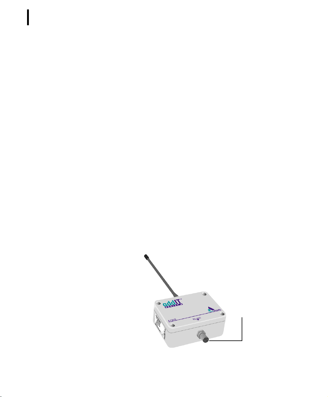
Installing the receiver
The receiver communicates over an RS485 interface. The receiver
and the RTU look very much like, except that the receiver has only
one connector, which links the receiver to the power supply.
Figure 1 illustrates the addIT receiver.
Figure 1. addIT Receiver
TO
POWER
SUPPLY
Page 11
Follow these steps to install the receiver part of the base station.
1. Locate the best site for the receiver and mount a rod on the
spot. The best site is usually on top of a roof or a mast.
2. Using the provided ring clamps, attach the receiver to the
rod.
3. Attach the female connector on the cable to the male
connector on the receiver by turning the plug’s fastening
screw.
Note: Standard cables are 30 m (approx. 99 ft) long. If you need a
longer cable, you can purchase additional cables to extend
the length up to 500 m (1640 ft).
4. Secure the cable to the rod with ties.
5. Bring the unattached end of the cable into the area where
your computer is.
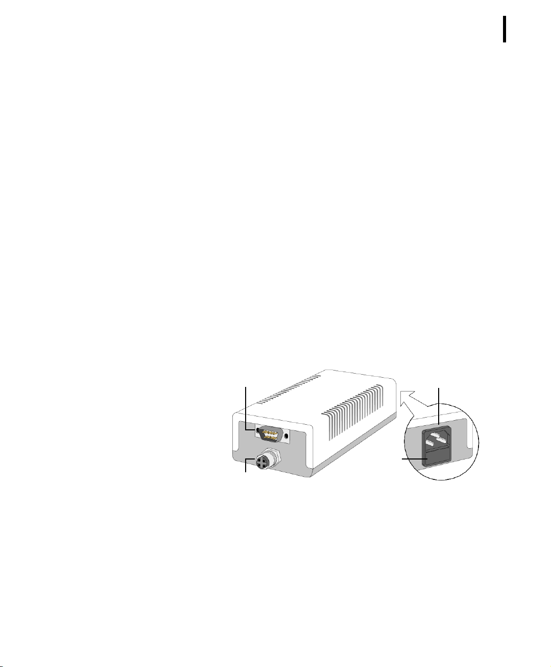
Installing the power supply
The A720PS power supply is the connection between the receiver
and your computer. The power supply is universal and operates
from 85 to 240 volts. Adcon supplies the serial cable and power
cord. Figure 2 illustrates the addIT power supply.
CHAPTER 2
Installing the base station
11
RS-232 SERIAL PORT
FUSE
RS-485 SERIAL PORT
Figure 2. addIT Power Supply
MAINS
Follow these steps to install the power supply:
1. Attach the cable from the receiver to the power supply.
2. Attach one end of the serial cable to the power supply and
the other end to an available serial port on your computer.
Page 12
CHAPTER 2
12
Using the Base Station
Note: The serial cable ends are identical, so it doesn’t matter which
you use in each location.
3. Plug the appropriate ends of the power cord into the power
supply and the power source (outlet).
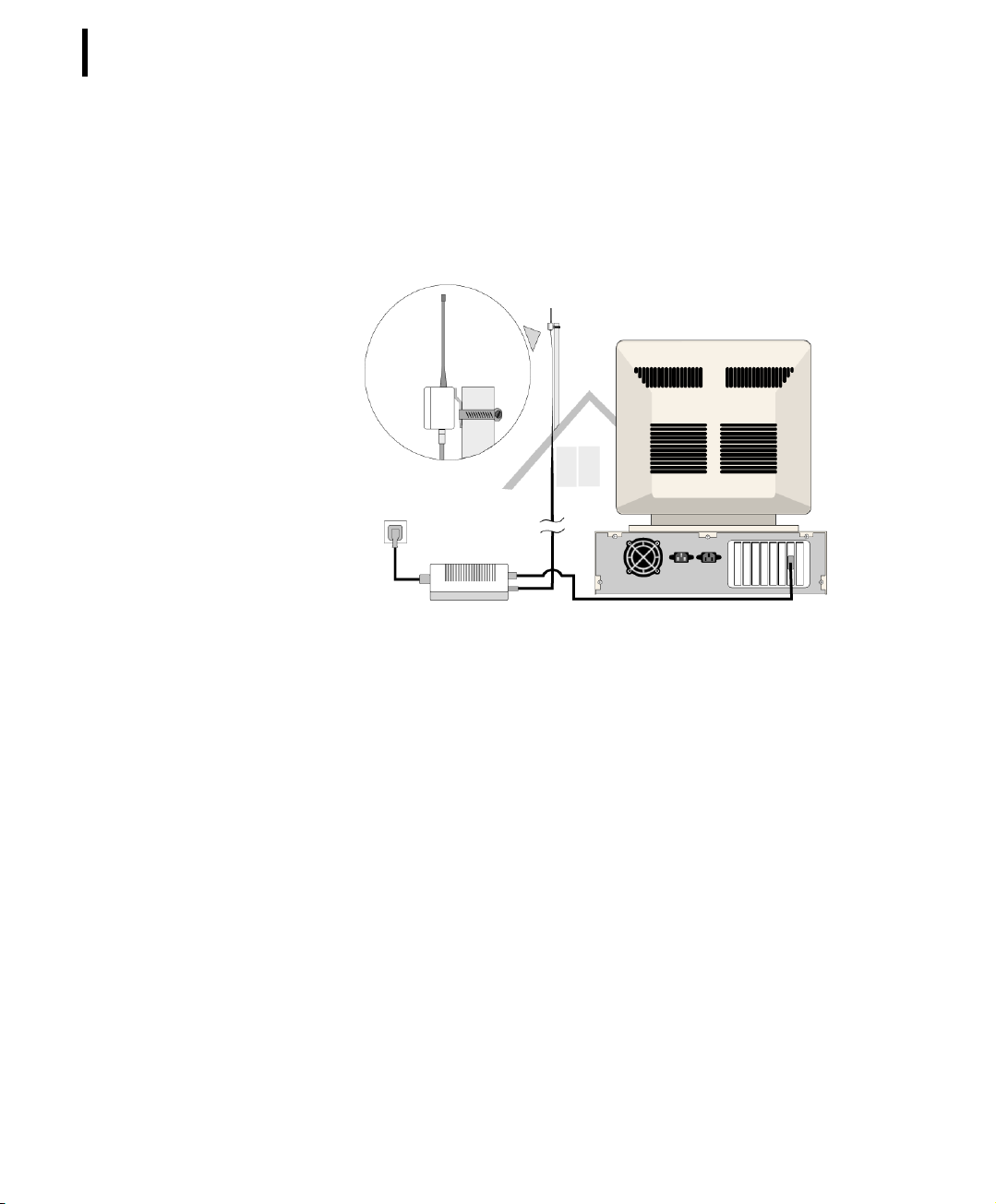
Figure 3 shows the base station configuration.
Replacing the fuse
Should you need to replace the fuse, simply remove the old fuse
from the power supply and insert a new 250 mA 250 V fuse.
Configuring the software
This manual details hardware installation only. Refer to the
addVANTAGE 4.1 Lite Reference Manual
using addVANTAGE Lite software.
If you are experienced in technical software issues, you can also
perform some configuration with the receiver by using a terminal
window. See “Configuring the devices” on page 24 for these
instructions.
Figure 3. Base Station Configuration
for instructions about
Page 13

Chapter 3. Using the RTU
13
Remember that the addIT A720/A723 remote telemetry units
(RTUs) can be used either with the A730 system or as standalone
systems with the A720B base station. The base station is discussed
in “Using the Base Station” on page 9.
Opening the packages
You get several boxes when you purchase an addIT RTU. When
you open them, you’ll see they contain:
• The A720/A723 RTU and ring clamp
• The solar panel, ring clamp, and connecting cable
• The aluminum rod and its cap
•A sensor and cable, one box for each sensor, with a fastening
tie in each sensor box
• An LED tool
Make sure you’ve received all the equipment and read thr ough the
instructions that follow. When you’re sure you understand them,
you’re ready to install your RTU.
Page 14
CHAPTER 3
14
Using the RTU
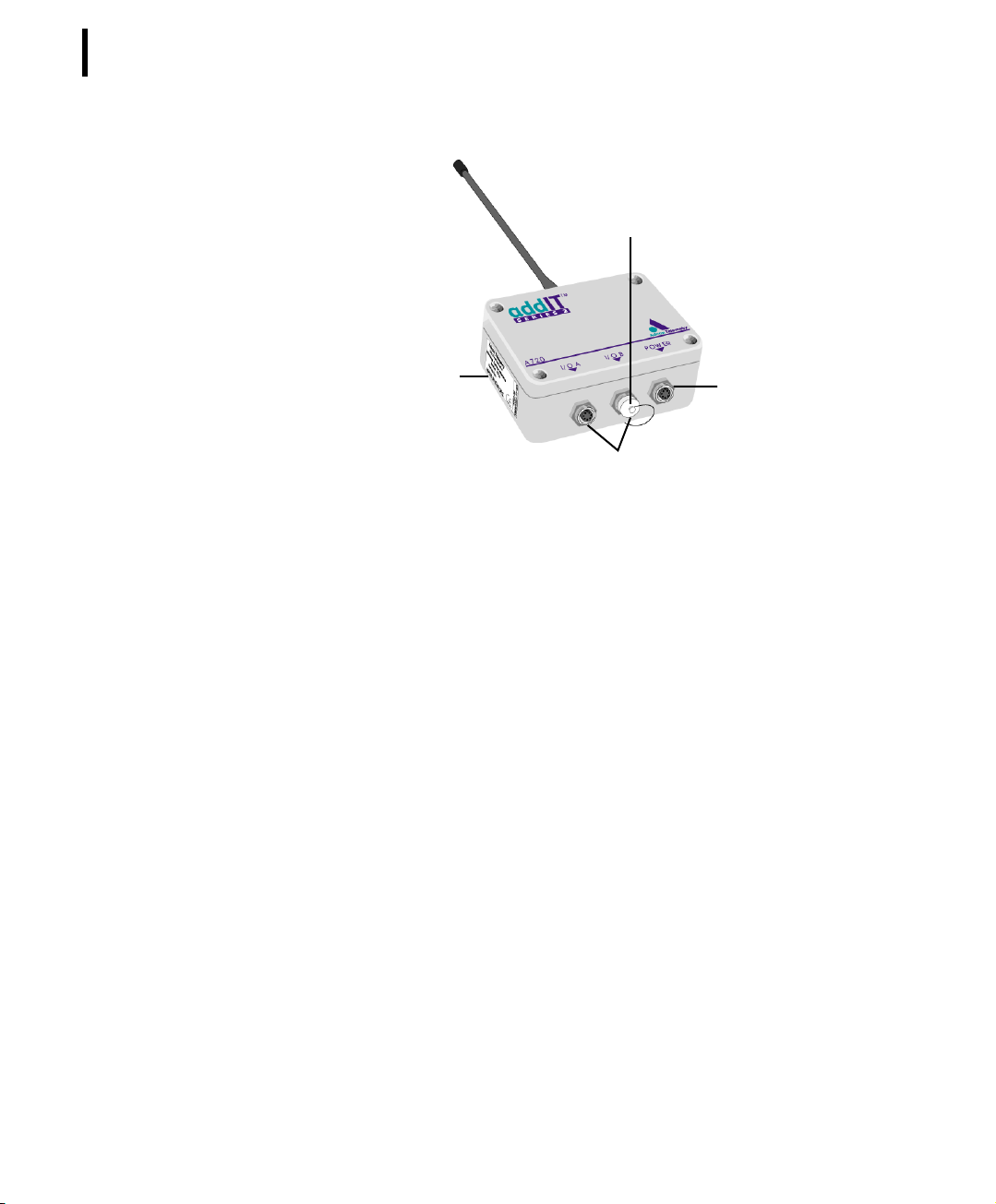
Figure 4 shows an addIT RTU.
Installing the RTU
Installing addIT RTUs in the field is a fairly simple process. You’ll
perform a connectivity check with an LED tool (addIT devices don’t
have a built-in LED like the A730MD stations do).
Note: The LED tool is a blind plug to be plugged in the
Follow these steps to install an addIT RTU in the field:
SERIAL
NUMBER
connector.
PROTECTIV
Figure 4. addIT RTU
E CAP
TO
SENSORS
TO
SOLAR
PANEL
POWER
1. Review the installation area and choose the best site.
2. Perform a connectivity check using the LED tool:
a. Insert the LED tool in the
POWER
connector and wait up to
10 seconds. If the unit connects to at least one station (or
a base station), it will light up the LED for about 4
seconds.
b. Keep observing the LED tool and, after another several
seconds, the LED will blink one or more times (the
number of blinks indicates the number of stations it has
contacted).
3. Using a hammer, drive the supplied aluminum rod into the
ground. How far you drive the rod into the ground depends
Page 15

CHAPTER 3
Installing the RTU
on your application. Put a plastic cap on top of the rod to
protect it.
4. Using a ring clamp, fasten the solar panel onto the aluminum
rod. Ensure that the panel is facing south (north if you are
located in the southern hemisphere) and out of the way of the
addIT RTU.
Note: The solar panel can be mounted under or behind the addIT
RTU, but be sure that the RTU does not shadow the panel.
5. Fasten the addIT RTU to the top of the rod using another ring
clamp. Adcon recommends that you perform another
connectivity test, if you can, to check the positioning of the
device.
6. Attach the sensors to the
to the
connector by turning the plugs’ fastening screws
POWER
connectors and the solar panel
I/O
clockwise until secure.
WARNING
If you turn the fastening screws too tightly, you could
damage the plugs.
7. Secure the extra length of the sensor cables to the rod with
ties.
15
Figure 5 shows what a typical RTU field installation looks like.
Figure 5. RTU in the Field
Page 16

CHAPTER 3
16
Using the RTU
This completes the installation of your addIT RTU. If one of the
connectors is left unused, use the cap specially provided to protect
it against moisture and dust. Be sure to make a note of the following information because you’ll need it when you configure the
device in the software:
• Serial number for each RTU
•Type of sensors connected to each RTU
More about the LED tool
The LED tool allows you to rapidly check the status of an addIT
RTU. After you insert the LED tool into the POWER connector, the
unit waits up to two seconds and then sends a broadcast frame. If a
nearby listening station or receiver decodes the frame, it will
answer back—this may take up to 10 seconds. When an answer is
received, the LED tool lights up for about 4 seconds. After another
few seconds, the LED lights up one or more times, depending on
the number of stations/receivers that answered to its broadcast
frame.
Note: addIT RTUs do not respond to a broadcast frame, only
remote stations (A730MD) and base stations (A730SD or
A720B).
In addition, the LED always blinks briefly at 0.5 second intervals to
indicate that the unit is alive and the internal battery has enough
energy to operate. If the blinking interval lengthens to 2 seconds,
the battery has become undercharged (that is, under 5.6 volts but
over 5.2 volts)—this is called the
addIT RTU reduces its activities to a minimum. The radio unit is
switched off, the sensor sampling ceases, and no data is stored in
the internal memory . Only the internal real-time clock is maintained
and the power management functions are performed.
misery
state. In this state, an
I/O
If the battery level drops below 5.2 volts, the system switches completely off, effectively decoupling itself from the battery in or der to
protect it. In this case the LED tool stays permanently off. An addIT
RTU in such a situation will restart only after connecting it to an
external power supply (even a solar panel under low light conditions).
Note: New addIT RTUs are delivered with their internal batteries
unformatted, meaning they are completely discharged, and
you should install them only on sunny days. The battery will
Page 17

Maintaining and servicing the RTU
be fully charged after two consecutive sunny days, but you
should get an LED light-up after several minutes of charging
in the sunlight.
Configuring an addIT RTU in the addVANTAGE software
If you’re using an addIT RTU with an A730 system, you can configure the RTU by following the steps described in the
A730 Releases Notes for Version 3.35
User Manual
Lite, follow the steps described in the addVANTAGE 4.1 Lite Reference Manual.
. If you’re using the addIT RTU with addVANTAGE
or in the
addVANTAGE
addVANTAGE 3.40
Maintaining and servicing the RTU
The A720 and A723 units need virtually no maintenance. They are
waterproof and designed to withstand harsh environmental conditions (-30 to +70 °C, or -22 to 158 °F), high RH values, water, and
other noncorrosive liquids. They conform to the European protection class IP65. This applies also to the connectors, as long as they
are mated. Don’t let unmated connectors on either the addIT RTU
or the sensors be exposed to the environment for extended periods of time.
CHAPTER 3
17
The RTU battery
Note: The same type of battery is used in the A720/A723 and
A720B devices, so the information in this section also
applies to the A720B.
The internal battery supplies 6.2 volts and consists of a NiCd pack.
The internal electronics manage the battery charging/discharging
process, ensuring it a long life. This approach, coupled with a
remarkably low average consumption (some mere 6 mW), allows
an addIT RTU to operate at least one month on a fully charged
battery, with the following conditions:
• The channel has moderate radio activity, with requests every
15 minutes.
•Total consumption of attached sensors is no more than 50
mA.
• The sensors are sampled once every 5 minutes and an
averaged slot is stored in the internal memory every 15
minutes.
Page 18

CHAPTER 3
18
Using the RTU
Table 1 shows the addIT devices’ expected operation time on a
fully charged battery with 50 mA total consumption for the sensors,
as described above.
Table 1. addIT Device Operation Time
Radio
Activity
No No sensors 450 92
Yes No sensors 540 77
Yes 1 750 55
Yes 3 (default) 1080 38
Yes 5 1450 28
Yes 15 3100 13
Sensor Sampling
(samples/15 min)
Average
Consumption
(µA)
Estimated
Operation
(days)
Note: Radio activity refers to the fact that one base station and
between one and three A730MD or addIT remote stations
are active on the same operating frequency as the addIT
remote station under test.
However, if for some reason (wear-out or accident) the battery
loses its capacity (noted in the software with repeated “Battery
low” messages), it must be replaced. Make sure, though, that the
problem is really due to the battery and not to a defective or dirty
solar panel.
Note: The solar panel works only with the A720/A723 devices. The
A720B receiver’s internal battery is charged by the power
supply.
Adcon highly recommends that you check the solar panels’ state
and clean them often. The rain droplets can splash thin layers of
soil on the panels, greatly reducing their power output. The surrounding vegetation can also lower the panels’ efficiency.
Changing the battery
Note: The same type of battery is used in the A720/A723 and
A720B devices, so the information in this section also
applies to the A720B.
Page 19

CHAPTER 3
Maintaining and servicing the RTU
If you have verified that the battery needs to be replaced, follow
these steps to do so:
1. Open the lid by unscrewing the four screws in the corner of
the addIT RTU.
2. Gently remove the lid (the battery is fixed on the lid and is
connected to the electronics board by means of a connector).
3. Remove the battery’s plug from the PCB connector.
4. Remove the battery pack from the lid (it is taped to the lid)
and replace it with a new one (obtainable from Adcon).
5. Insert the battery plug into the PCB connector.
6. Mount the lid back, taking care that the rubber gasket sealing
the box is not out of place.
WARNING Be sure to mount the rubber gasket properly, so that
the unit’s IP65 environmental protection is not affected.
7. Screw the four screws back in, applying a moderate force.
19
Page 20

CHAPTER 3
20
Using the RTU
Page 21

Chapter 4. Performing Advanced
Functions
21
With the appropriate knowledge, you can configure the addIT
devices in the field by using a hyperterminal window. To configure
the RTU, you will need a special serial cable adapter (not supplied,
available from Adcon).
CAUTION Do not try to configure your addIT devices if you are
not sure what to do—the unit may not communicate with the
remote measuring station or function with the addVANTAGE
software.
WARNING Tampering with parameters for the addIT devices may
void your warranty or damage the device. In general, the
commands described in this chapter are intended for technical
support staff and users with a great deal of highly technical
hardware and software experience.
In the system architecture, the base station and RTU are both considered to be nodes. The base station is called the master node, or
master, while the RTU is called the slave node, or slave.
Page 22

CHAPTER 4
22
Performing Advanced Functions
Device series
Currently, two A720 device versions are in use: Series 1 and
Series 2. in addition, since begin of 2001, Adcon introduced also
the Series 3 model (A723). You can determine which series a
device is in any of these ways:
• The VER command (see pages 29 and 52). When the device is
connected, you can type this command to the series. With a
Series 1 device, the command returns VER 1.0 or higher,
while with a Series 2 device, the return is VER 2.0 or higher.
This is the most reliable method of determining which series
you have. To differentiate between A720 and A723 devices,
type the command TYPE, and an A723 will return the string
TYPE A723.
• The logo on the front of the device. Series 2 devices include
such wording on the logo. However, if you returned a Series 1
device for repair, it is possible that it was replaced with a
Series 2 motherboard. In such a case, you would have a
Series 2 device in Series 1 housing. Series 3 devices (A723)
are marked as such.
Understanding connectors
The addIT devices have cable attachments called connectors. The
connector type determines how the device communicates with the
sensors or the computer.
The receiver connector
The addIT A720B receiver has one 4-pin connector. Figure 6 illustrates this connector and Table 2 details the connections.
Figure 6. addIT Receiver Connector (Top View)
1
Gnd
2
3
BA
V+
4
Page 23
The RTU connectors
CHAPTER 4
Understanding connectors
Table 2. addIT Receiver Pin Functions
1 Bus Power (V+)
2 Bus Power (GND)
3 Bus Communications (B)
4 Bus Communications (A)
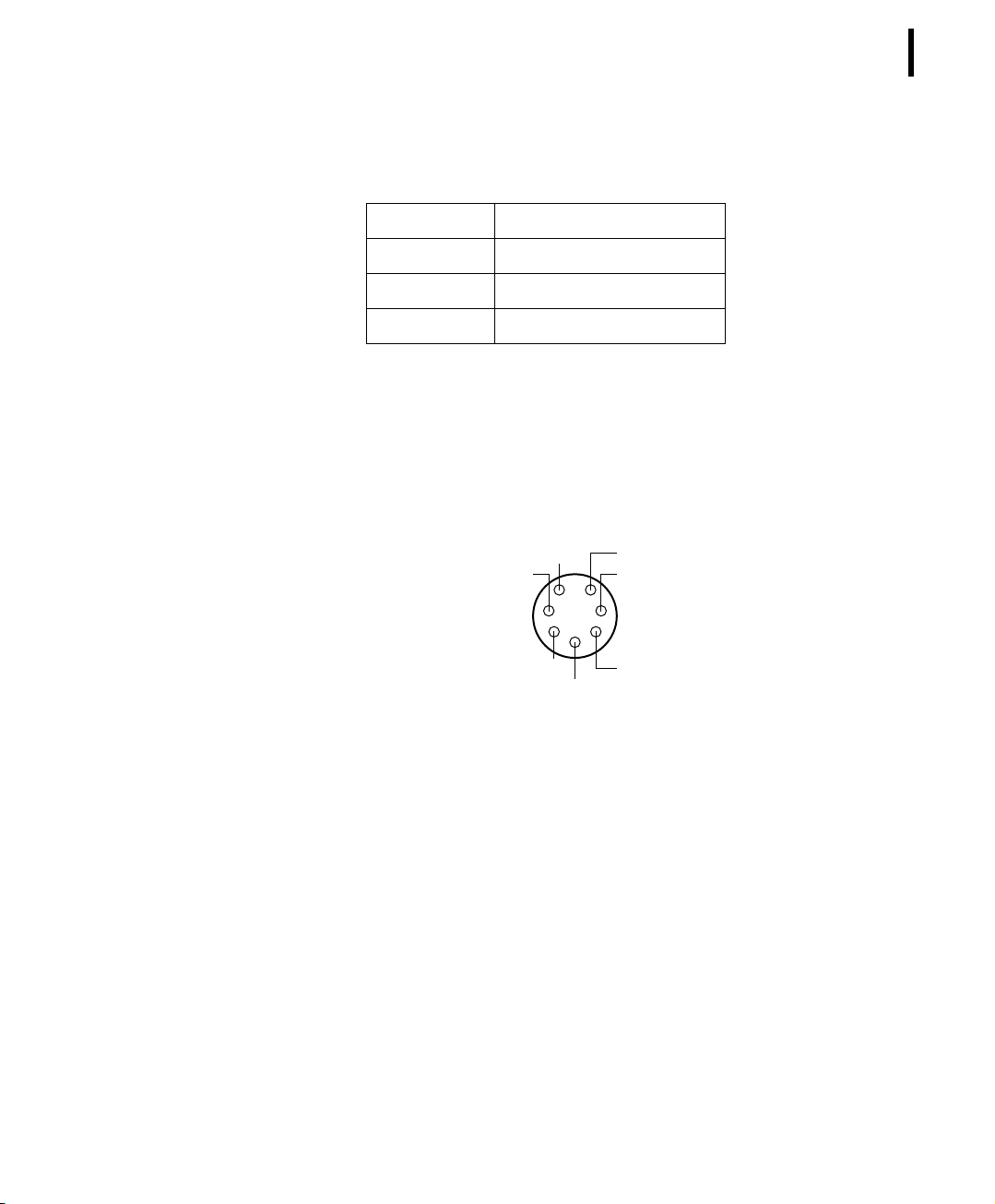
The addIT RTU uses standard 7-pin sensor I/O A and I/O B connectors (model Binder 702 and 712 series or equivalent) that are
identical. Each connector contains three analog inputs (0 to 2.5
volt) and two digital input/outputs, one of which you can use as a
pulse counter (for example, a rain gauge). Figure 7 illustrates the
individual pins of an I/O connector.
Switched Battery
Digital I/O
6
5
Cabling 1
Cabling 2
7
1
2
3
4
(Analog In)
(Analog In)
23
Pulse Counter
Ground
Figure 7. Pins on an I/O Connector (Top View)
Cabling 3
(Analog In)
If you have a special passive extender cable, you can use it to plug
more than one sensor to one connector.
CAUTION To avoid cabling conflicts, first verify in the
addVANTAGE software that the sensor combination in the
configuration you want is allowed. If there are no conflicts, you can
physically attach the sensors to the addIT RTU.
addIT RTUs can also be used to control actuators and to switch on
or off pumps, valves, or other similar devices (for example, using
the Macro extension). The same principles for macro commands
using an A730MD remote measuring devices apply to addIT RTUs,
with the sole difference that instead of three, only the first two outputs are available.
Page 24

CHAPTER 4
24
Performing Advanced Functions
The RTU also has a POWER connector. Figure 8 illustrates the connections available at the POWER connector.
Figure 8. addIT RTU POWER Connector (Top View)
WARNING The RxD and TxD connections are not RS-232
compatible.
This configuration allows the use of external power supplies or
extra batteries (contact Adcon for further details).
Configuring the devices
You can use a Windows Hyperterminal window to connect to either
addIT device. After you have installed the system, follow these
steps to configure the device:
Note: To configure the A720B receiver, use the serial cable that
comes with the system. To configure the A720 or A723 RTU,
you must have the special adapter cable (available from
Adcon) and plug it into the POWER connector.
Ext Power
Battery
5
1
4
3
Ground
RxD
2
TxD
1. Open a Hyperterminal window.
2. Select the appropriate serial port and click OK.
3. Configure your terminal as follows:
• 19200 baud
•1 stop bit
•8 data bits
• No parity
• No flow control
• Send LF after CR
4. Select OK to open the terminal window.
5. Press Enter to generate a response in the window.
Page 25

Serial communication protocol
This protocol is based on a master sending commands and a node
answering; the whole communication is conducted in plain ASCII,
as strings. When exchanging numbers, they are represented in
decimal format. All commands are terminated with a CR/LF combination. All responses (answers) are terminated with the # character.
General format of a command
The commands have the following format:
ID Command Param1 Param2 ... ParamN
• ID is the destination device. If you include an ID as part of a
command, the node checks whether ID=ownID. If it does,
the node executes the command on itself. If the ID is not the
node’s ID, the node executes the command on a remote
device, if such an ID exists. If the ID is missing, this implies
that the command is addressed locally.
CHAPTER 4
Serial communication protocol
25
Note: Not all the commands can be relayed remotely.
• Command is the command proper, which can be composed of
a variable string of characters (for example, SLOT). Each node
can implement a set of commands depending on the
functionality of the node itself. However, as a minimum
requirement, a node recognizes the CMDS command, which
returns a list with the commands recognized by the node.
• Param1 Param2 ... ParamN represent the parameters,
which are command dependent. If you type no parameters
when you issue a command, it is the equivalent of querying
for information (the GET version of a command). If you type
parameters, you are issuing the SET version of a command
and are setting the command to the parameters you typed.
General format of an answer
The answers have the following format:
ID Command Result1 Result2 ... ResultN ErrResult #
• ID is the answering device. If a command was further routed,
it is the ID of the end device. The answer must always contain
the ID on return.
Page 26

CHAPTER 4
26
Performing Advanced Functions
• Command is the string repr esenting the original command. It is
supplied so that a master can distinguish between the
answers it is waiting for, and out-of-band notifications (which
may come, for example, over the radio port of a node). As
with the ID, the command name must be always supplied.
• Result1 Result2 ... ResultN are the result values
returned by the remote node. If the ErrResult is not zero,
all other possible characters and/or strings until the end of the
line may be ignored.
• ErrResult shows whether the command was successfully
executed. If this value is 0, the command was successfully
executed. If this value is other than 0, the command failed.
The number may further indicate the error type. (See also
“Returned errors list” on page 54.)
The answer string may contain any number of spaces or CR/LF
characters between its components; however, after the terminator
(#) no other characters are allowed.
Using terminal commands
Following is a list of available commands and an explanation of
their use.
Note that for Series 1 devices, you preface a change in a setting
with SET, while with Series 2 devices you do not.
Note: You can type uppercase or lowercase characters because the
commands are not case sensitive.
Series 1 devices
The SET series of commands
COMMAND SET OWNID nnnn
DESCRIPTION Sets the identification of the unit.
PARAMETERS nnnn is the ID number of the unit.
RETURNS Nothing.
REMARKS The ID number must be identical to the one written on the unit’s
label.
Page 27

CHAPTER 4
Using terminal commands
EXAMPLE SET OWNID 2003
COMMAND SET PMP bl bh
DESCRIPTION Sets the power management parameters.
PARAMETERS bl is the lower battery level (the threshold where the charging of
the battery is switched on) and bh is the higher battery level (the
charging is switched off).
RETURNS Nothing.
REMARKS Both bl and bh are expressed in volts X 10 (for example, 72 actually
means 7.2 V). Default values (factory programmed) are 65 and 72,
meaning 6.5 and 7.2 volts respectively.
EXAMPLE To change the switch-on threshold to 6.3 and the switch-off thresh-
old to 7.0 volts:
SET PMP 63 70
27
COMMAND SET SLOT storage samples
DESCRIPTION Configures the input sampling and storing intervals.
PARAMETERS storage represents the time (in seconds) elapsed between two
slots stored in the internal memory, while samples represents the
numbers of samples used to build the average that will be stored.
RETURNS Nothing.
REMARKS The default storage is 900 (15 minutes) and samples is 3 (3 sam-
ples per quarter of an hour).
EXAMPLE To sample the inputs (sensors) every minute and build an hourly
average:
SET SLOT 3600 60
To sample the inputs once per hour and store the values as they
are:
SET SLOT 3600 1
Page 28

CHAPTER 4
28
Performing Advanced Functions
WARNING Changing the above parameters may adversely affect
the ability of the device to operate for extended periods under low
solar radiation conditions when used with addVANTAGE 3.x. Even
if you change them, addVANTAGE will not display the charts
accordingly: the current addVANTAGE version supports only 15minute data slots. Changing the storage parameter to lower than
60 or higher than 1500 will lead to a total data loss in
addVANTAGE 3.x. This warning does not apply to usage with
addVANTAGE 4.x Lite software.
COMMAND SET FREQ freq step
DESCRIPTION Sets the unit’s operating frequency.
PARAMETERS freq is the frequency and step is the channel spacing (both
expressed in Herz).
RETURNS Nothing.
REMARKS Convert values to Herz before issuing the command.
EXAMPLE To change the frequency to 467.1125 MHz with a channel spacing
of 12.5 kHz:
SET FREQ 467112500 12500
CAUTION Do not change the frequency of your device without
reason: apart from the fact it may not communicate in the network
anymore, you may also violate the applicable radiocommunications laws in your country. Depending on the destination country,
some models may also return an error message.
COMMAND SET RSSI value
DESCRIPTION Sets the Relative Signal Strength Indicator threshold.
PARAMETERS value is the RSSI setting.
RETURNS Nothing.
REMARKS The factory default is set to 58 units. The RSSI threshold is used to
detect if any radio activity is on the channel. The value set must be
approximately 30% higher than the actual measured value when no
signal is present on the channel. To measure the actual value, use
the command RSSI (see "Querying the actual configuration
parameters").
Page 29

EXAMPLE To set the RSSI threshold to 58:
SET RSSI 58
Querying the actual configuration parameters
You can query an addIT to find out its actual configuration parameters (GET the parameter). Typing OWNID, for instance returns the
actual ID an addIT answers to (it should be the same as the one on
its label). In addition to OWNID, PMP, SLOT, FREQ, and RSSI, the
command VER returns the current software version of the device.
The RSSI commands returns two values: the actual measured
value of the RSSI and the value set as threshold. As noted elsewhere, the threshold must be approximately 30% higher than the
actual measured value. The actual RSSI is unstable due to the
channel’s random noise, receiver’s internal noise, and/or to transmissions just taking place. If the actual RSSI value is consistently
higher than the programmed value, something must be wrong, or
the channel is very noisy (however, before readjusting the RSSI
threshold, check this with a handheld radio receiver or a scanner).
CHAPTER 4
Using terminal commands
29
Other commands available in terminal mode are:
• DUMP addr—displays 256 bytes of the internal EEPROM
memory, starting with the address addr (specified as hex
values). Valid addr esses for the model A720 are B600 to B9FF.
The last 16 slots of data (for 15-minute slots, that makes 4
hours of data) are stored at B900 to B9FF. The remainder are
used for internal configuration parameters or reserved for
future use.
• RX—switches the device to receive mode until a key is
pressed. This command is used for trimming or checking
purposes.
• XMIT param—switches the device to transmit mode until a
key is pressed. This command is used for trimming or
checking purposes. param may be any of the following:
• 0—a 2 kHz tone will be modulated on the transmitted
carrier
• 1—a 1 kHz tone will be modulated on the transmitted
carrier
• T—a mixture of 1 and 2 kHz test tones
• Not given—an unmodulated carrier will be transmitted
Page 30

CHAPTER 4
30
Performing Advanced Functions
• B – sends a broadcast frame and displays all the answers.
Series 2 and 3 devices
Note: With Series 2 and 3 devices, typing the command by itself is
a GET command, while typing the command with parameters or variables is a SET command.
COMMAND CMDS
APPLIES TO A720, A720B, A723
DESCRIPTION Returns a list of supported commands.
PARAMETERS None.
REMARKS GET only.
RETURNS A list of strings separated by spaces.
REMOTE No.
EXAMPLE CMDS
193 CMDS CMDS ID PMP RSSI TIME FREQ DEV DEL REPL
SLOT DATA INFO RX TX ERA 0
#
COMMAND TIME
APPLIES TO A720B, A723
DESCRIPTION Sets/returns the real time clock.
PARAMETERS The actual time, or none in the GET version.
RETURNS The actual time as dd/mm/yyyy hh:mm:ss.
REMARKS GET/SET.
REMOTE No.
EXAMPLES TIME 12/12/1998 22:10:10
193 TIME 0
#
TIME
193 TIME 12/12/1998 22:10:10 0
#
Page 31

CHAPTER 4
Using terminal commands
COMMAND FREQ
CAUTION Do not change the frequency of your device without
reason. Apart from the fact that it may not communicate with the
network anymore, you may also violate the applicable radiocommunications laws in your country. Depending on the
destination country, some models may also return an error
message when trying to use this command.
APPLIES TO A720, A720B, A723
DESCRIPTION Sets/returns the operating frequency.
PARAMETERS The operating frequency and step (Hz), or none in the GET version.
RETURNS The actual frequency and step, in Hz.
REMARKS GET/SET.
REMOTE Yes, SET only.
EXAMPLE FREQ 433925000 25000
193 FREQ 0
#
31
FREQ
193 FREQ 433925000 25000 0
#
COMMAND RSSI
APPLIES TO A720, A720B, A723
DESCRIPTION Sets/returns the Relative Signal Strength Indicator threshold at
which an RF receiver must wake up.
PARAMETERS The threshold value. For the A720 family, it can take values from 0
to 255; it is typically factory set to 58. For the A723, it typically factory set to 42.
RETURNS The instant RSSI value and the programmed threshold.
REMARKS The factory default is set to 58 units. The RSSI threshold is used to
detect if any radio activity is on the channel. The value set must be
approximately 30% higher than the actual measured value when
no signal is present on the channel. To measure the actual value,
use the command RSSI with no variables or parameters.
Page 32

CHAPTER 4
32
Performing Advanced Functions
REMOTE No.
EXAMPLE RSSI 58
193 RSSI 0
#
RSSI
193 RSSI 44 58 0
#
COMMAND ID
APPLIES TO A720, A720B, A723
DESCRIPTION Sets/returns the node’s ID.
PARAMETERS The node ID.
RETURNS The node ID.
REMARKS GET/SET.
REMOTE Yes, SET only.
EXAMPLE ID 4557
193 ID 0
#
ID
4557 ID 4557 0
#
6556 ID 7557
6556 ID 0
#
Note: The last example shows a case where a remote node was
instructed to change its own ID from 6556 to 7557. Even if it
changed its ID, it answers with the old ID in order to correctly finish the transaction.
COMMAND SLOT
CAUTION Changing these parameters may adversely affect the
ability of the device to operate for extended periods under low
solar radiation conditions.
Page 33

CHAPTER 4
Using terminal commands
APPLIES TO A720, A720B, A723
DESCRIPTION Sets/returns the input storing and sampling intervals.
PARAMETERS storage represents the time (in seconds) elapsed between two
slots stored in the internal memory, while samples represents the
numbers of samples used to build the average that will be stored.
RETURNS The interval and rate.
REMARKS The default storage is 900 (15 minutes) and samples is 3 (3 sam-
ples per quarter of an hour).
REMOTE Yes, SET only.
EXAMPLE SLOT 900 3
193 SLOT 0
#
SLOT
193 SLOT 900 3 0
#
33
Note: The A720B base station needs only the rate. For consis-
tency, however, it accepts both parameters and discards the
one it doesn’t need.
COMMAND PMP
APPLIES TO A720, A720B, A723
DESCRIPTION Sets/returns the node’s Power Management Parameters (switches
on/off the battery charge).
PARAMETERS The lower (switch on) and the higher limit (switch off), both in volts
x 10. Standard V alues are 65 (for 6.5 Volts) for switch on and 72 (for
7.2 Volts) for switch off.
RETURNS The lower (switch off) and the higher limit (switch on), both in volts
x 10.
REMARKS GET/SET.
REMOTE Yes, SET only.
EXAMPLE PMP 65 72
193 PMP 0
#
Page 34

CHAPTER 4
34
Performing Advanced Functions
PMP
193 PMP 65 72 0
#
COMMAND CM
APPLIES TO A723
DESCRIPTION Sets/returns the A720 compatibility mode.
PARAMETERS 0 means A723 native mode while 1 switches the unit in A720 com-
patible mode. In this mode, although the device presents itself as
an A723 (when issuing the INFO command), it will return the frame
type 38 when asked for DATA (see also “DATA” on page 36). This
mode is useful when the A723 device is used with the A720B base
station or with an addVANTAGE 3.35 software (addVANTAGE 3.4
and later recognizes an A723 in its native mode).
There is also an additional compatibility mode (CM 2) that forces
the A723 to respond with an A720 compatible answer to the INFO
command. This mode is not recommended for normal use.
By default the A723 devices are delivered in native mode (CM is 0).
RETURNS The current mode.
REMARKS GET/SET.
REMOTE No.
EXAMPLE CM 1
193 cm 0
#
CM
193 CM 1 0
#
COMMAND SST
APPLIES TO A723
DESCRIPTION Sets/returns Sensor Sampling Time. This is the delay allowed for
the sensors to settle after applying them power and until they are
sampled.
PARAMETERS The settling time in seconds.
Page 35

Using terminal commands
RETURNS The actual sensor settling time (default is 2 seconds).
REMARKS GET/SET.
REMOTE No.
EXAMPLE SST 2
193 sst 0
#
SST
193 sst 2 0
#
COMMAND DEV
APPLIES TO A720B
DESCRIPTION Inserts/reads the devices in the local devices list.
PARAMETER The device to be inserted (in the SET version).
CHAPTER 4
35
RETURNS The devices list (in the GET version). The GET version displays
additional information about the devices, such as the last slot in
the local memory and a flag showing whether a notification is
pending (for more details about notifications, see “Notifications”
on page 53).
REMARKS GET/SET.
REMOTE No.
EXAMPLE DEV 5667
193 DEV 0
#
DEV
193 DEV
5667 22/1/1999 19:39:40 0
5668 21/1/1999 15:26:54 0 0
#
COMMAND REPL
APPLIES TO A720B
DESCRIPTION Replaces a device ID by another device ID in the local devices list.
Page 36

CHAPTER 4
36
Performing Advanced Functions
PARAMETERS The old ID and the new ID.
RETURNS Nothing.
REMARKS SET only.
REMOTE No.
EXAMPLE REPL 5667 5666
193 REPL 0
#
REPL
193 REPL 5
#
Note: The second example shows a REPL command without
parameter: error 5 is returned (missing or false parameter).
COMMAND DEL
APPLIES TO A720B
DESCRIPTION Deletes a device from the local devices list.
PARAMETERS The ID of the device to be deleted.
RETURNS Nothing.
REMARKS SET only.
REMOTE No.
EXAMPLE DEL 5666
193 DEL 0
#
DEL
193 DEL 5
#
Note: The second example shows a DEL command without param-
eter: error 5 is returned (missing or false parameter).
COMMAND DATA
APPLIES TO A720, A720B, A723
Page 37

CHAPTER 4
Using terminal commands
DESCRIPTION Returns data stored for a certain device.
PARAMETER The ID of the device for which the data is requested and the date/
time (in the standard format) the data was stored. If missing, then it
refers to the data of the local device.
RETURNS A data block.
REMARKS GET only. If you don’t include the date/time parameter, the latest
data is returned. If you include the date/time parameter, the date
and time closest to, but later than, the given date/time is returned.
REMOTE Yes, for a GET on the A720B and A723, but only one frame at a
time. If you are using a terminal window for the A720, you cannot
issue the DATA command remotely. If you are using a terminal window for the A720B, you can issue a DATA command for an A720 or
A723 RTU, but you cannot issue the command for the A720B
receiver. In other words, the base station can issue a remote command for an RTU, but it cannot issue such a command for itself.
The A720 RTU can issue the command only for itself, and only
locally, while the A723 RTU can also issue remote data commands.
37
EXAMPLE DATA 5666 12/12/1998 12:12:12
193 DATA b1 b2 b3 ... bn 0
#
The data block returned will typically contain a number of data
frames (telegrams). The structure of a block is as follows:
dd mm yyyy hh mm ss si ft d1 d2 ... dn dd mm yyyy
... dn cs
where:
• dd mm yyyy is the date
• hh mm ss is the time
• si is the size of the frame
• ft is the frame type (38 for addIT devices)
• d1 d2 ... dn are the data values (the frame content)
• cs is a 16-bit checksum obtained by summing the bytes and
discarding the carries over 0xFFFF
The A720 devices respond with a type 38 data frame, while the
A723 may respond with type 38 or type 39, depending on the CM
flag (see also “CM” on page 34). The most important difference
Page 38

CHAPTER 4
38
Performing Advanced Functions
between the frames 38 and 39 is that the later accomodates for 12
bit analog values for the sensor sampling inputs and 16 bit
counters for the pulse counter inputs. In addition, the correspondence between input analog and digital ports and their position in
the frame differs.
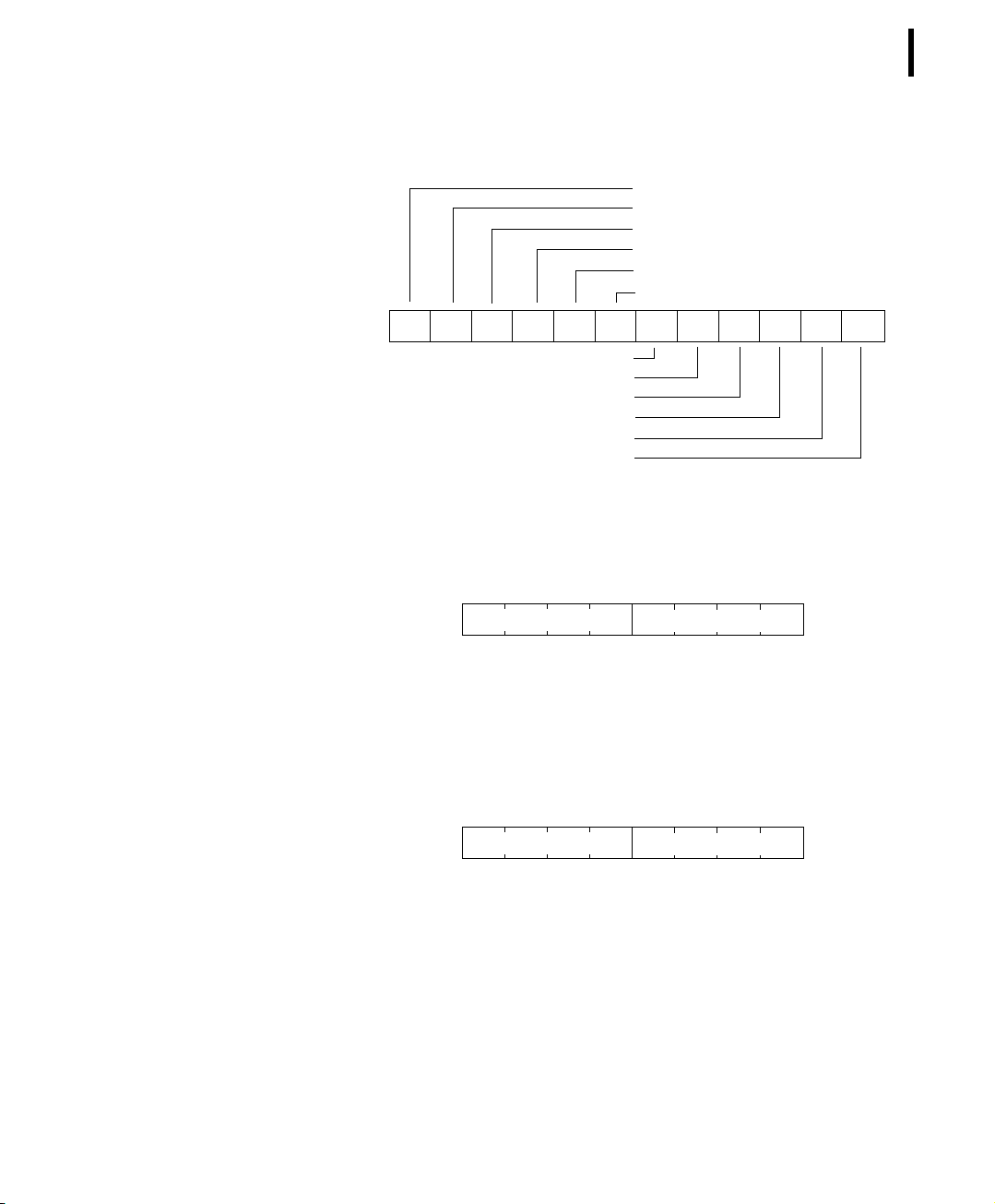
The composition of the data block of a frame type 38 (the bytes
marked as d1, d2... dn) is depicted in Figure 9, a type 39 frame in
Figure 10 while the digibyte is depicted in Figure 11 and
Figure 12.
RF incoming
RF outgoing
Digibyte
Pulse Counter I/O B
Pulse Counter I/O A
Battery
D1 D2 D3 D4 D5 D6 D7 D8 D9 D10 D11 D12 D13
Cabling 1 I/O B
Cabling 2 I/O B
Cabling 3 I/O B
Cabling 1 I/O A
Cabling 2 I/O A
Cabling 3 I/O A
Reserved
Figure 9. Frame 38 description
Page 39
CHAPTER 4
Using terminal commands
RF incoming
RF outgoing
Digibyte
Pulse Counter I/O A
Pulse Counter I/O B
Battery
D1 D2 D3 D4 D5 D6 D7 D8 D9 D10 D11 D12
Cabling 1 I/O A
Cabling 2 I/O A
Cabling 3 I/O A
Cabling 1 I/O B
Cabling 2 I/O B
Cabling 3 I/O B
Figure 10. Frame 39 description
39
b7 b0
SC Res U U Res Res Dig A Dig B
SC — Battery charge (0–off, 1–on)
Res — Reserved
U — Undefined
Dig A — Digital I/O A
Dig B — Digital I/O B
Figure 11. The Digibyte for an A720 device
b7 b0
SC Dig 6 Dig 5 Dig 4 Dig 3 Dig 2 Dig 1 Dig 0
SC — Battery charge (0–off, 1–on)
Note: Only Dig A and Dig B are wired externally
Dig n — Digital I/O A...X
Figure 12. The Digibyte for an A723 device
The remote version is limited to a single frame. An example of
such a command is given below:
6367 DATA 6367 30/4/1999 14:50:00
6367 DATA
Page 40

CHAPTER 4
40
Performing Advanced Functions
30 4 1999 14 54 55 14 38 255 255 77 0 0 89 156 126
20 0 0 0 0
3185 0
#
Notice that if you need to get data that is not the last (newest) slot
remotely from a device, the ID must be supplied twice. If you need
to get the last slot stored, you can ignore the ID and the date/time
parameters:
8300 DATA
8300 DATA
13 5 1999 19 26 36 14 38 255 255 79 0 0 87 148 149
15 0 0 0 0
3138 0
COMMAND IMME
APPLIES TO A723
DESCRIPTION Returns immediate data.
PARAMETERS None.
RETURNS A formatted string representing the data sampled on the input
ports.
REMARKS GET only. The answer to this command is delayed with the SST
time (see also “SST” on page 34). The values represent the normal
DATA frame values but formatted for easy human identification.
REMOTE No.
EXAMPLE IMME
16816 IMME 30 8 2001 16 15 06 13 39 0 0 127
0 0 95
0 0 0 0 0 0
2350 0
#
COMMAND ROUTE
APPLIES TO A723
DESCRIPTION Updates a routing table than will be used for remote commands
(e.g. DATA, INFO, etc.).
Page 41

CHAPTER 4
Using terminal commands
PARAMETERS The destination node and the intermediate nodes, on the order
starting from the issuing node to the traget (remote) node.
RETURNS The actual routing table (in GET mode).
REMARKS GET/SET.
REMOTE No.
EXAMPLE ROUTE 2419 10836
16816 ROUTE 0
#
ROUTE
16816 ROUTE
2419 10836 0
#
COMMAND FDEV
APPLIES TO A720, A720B, A723
41
DESCRIPTION Formats the internal memory (destroys all the data).
PARAMETERS None.
RETURNS Nothing.
REMARKS SET only.
REMOTE Yes, SET only.
EXAMPLE FDEV
193 FDEV 0
#
Note: Depending on the device’s memory size, this command may
take several seconds to complete.
COMMAND INFO
APPLIES TO A720, A720B, A723
DESCRIPTION Returns various status information.
PARAMETERS None.
RETURNS A list of a device’s internal variables:
Page 42

CHAPTER 4
42
Performing Advanced Functions
ID INFO rf_in rf_out date time ver clk stack cop
batt temp days_uptime min:sec_uptime rssi pmp_low
pmp_high type slot samples po err_level
#
The formats for the above parameters are as follows:
• rf_in and rf_out as a decimal
• date as dd/mm/yyyy
• time as hh:mm:ss
• ver as x.x
• clk, stack, and cop as decimal; they represent internal
housekeeping parameters and are implementation
dependent (the A720 uses cop to number watchdog
occurrences, but clk and stack are currently undefined for
the A720; for the A723 clk returns the SST – Sensor Sampling
Time value, default 2)
• batt as battery level using the standard voltage conversion
equation (0 is 0 volts, 255 is 20 volts)
• temp as internal temperature in the A720 housing, which is
device dependent. The precision of the sensing element is
very low (±4°C), but it is sufficient for battery power
management (charge/discharge). To compute the actual value
(in °C), the following equation must be used:
Temp internalTemp
1087
------------275–•=
255
• days_uptime in days; together with min:sec_uptime, it
represents the amount of time the device is up without a reset
or watchdog
• min:sec_uptime in minutes:seconds format
• rssi as decimal; it is the programmed value with the RSSI
command
• pmp_low and pmp_high ar e the programmed values with the
PMP command
• type is used to repr esent the device type; following types are
assigned currently:
— 0 for A730MD
— 1 for A720
— 2 for A730SD
— 3 for A720B
Page 43

CHAPTER 4
Using terminal commands
— 4 for A733
— 5 for A723
— 6 for A440
• slot and samples are the actual values programmed by
means of the SLOT command
• po (A723 only) is the relative output power
• err_level is the error value; 0 means no error
REMARKS GET only.
REMOTE Yes, GET only. The A720B and A723 can issue the command both
remotely and locally, while the A720 can issue the command only
locally.
EXAMPLE INFO
193 INFO 255 0 18/4/1999 21:5:11 1.3 0 0 0 91 72
40 1:46 58 65 72 3 900 0 0
#
COMMAND ANLG
43
APPLIES TO A723
DESCRIPTION Sets/returns various parameters of the analog subsystem (e. g. the
sampling/averaging method used for individual data aquisition
channels).
PARAMETERS A control byte specifying the command and the analog input chan-
nel number the command is acting on:
Command Code
Figure 13. The ANLG Control Byte Layout.
Channel Number
Some commands may also require one or two additional 16 bit
parameters representing threshold values.
• The Channel Number selects the analog channel that will be
affected by the command. For the A723 device, only 0000 to
0101 are accepted (only 6 analog channels are available).
Page 44

CHAPTER 4
44
Performing Advanced Functions
• The Command Code specifies the operation that will be
applied to the selected channel. They are described in the
table below:
Table 3. Command Code Definitions for the Analog Command
Code Description Parameters Returns
0000
0001
0010
0011
0100
0101
0110
0111
1000
RSM – Read Sampling Method. This command reads the current
programmed sampling method for all analog input channels.
SSMMI – Set Sampling Method to Minimum. The specified analog channel will be instructed to store the lowest sampled value.
SSMMA – Set Sampling Method to Maximum. The specified analog channel will be instructed to store the highest sampled value.
SSMS – Set Sampling Method to Sum. The specified analog channel will be instructed to store the sum of all sampled values.
SSMAA – Set Sampling Method to Arithmetic Average. The specified analog channel will be instructed to store the arithmetic
average of all sampled values.
SSMCA – Set Sampling Method to Circular Average. The specified
analog channel will be instructed to store the circular average of
all sampled values.
SSMF – Set Sampling Method to First. Only the first sampled
value will be stored in each slot.
SSML – Set Sampling Method to Last. Only the last sampled
value will be stored in each slot.
RNS – Read Notification Statusa. If no notification was pending,
this command should return an error. If one was pending, the
notification is cleared.
The current sampling methods and the
None.
The channel number. Result (OK or ERROR).
The channel number. Result (OK or ERROR).
The channel number. Result (OK or ERROR).
The channel number. Result (OK or ERROR).
The channel number. Result (OK or ERROR).
The channel number. Result (OK or ERROR).
The channel number. Result (OK or ERROR).
The channel number.
result (OK or ERROR). See also the table
that follows.
Returns the time when the threshold
was reached (in standard time format)
and the result (OK or ERROR).
RPNNER – Read the Pending Notifications and the Notification
1001
1010 DAN – Disable Any Notification. The channel number. Result (OK or ERROR).
1011 RNTTL – Read Notification Type and Thresholds/Limits. The channel number.
Enable Register. This command returns the 16-bit Pending Notifications and the Notification Enable Registers; the Port Number
has no significance for this command.
None.
Two 16-bit integers (first the PN and
then the NE register) and the result (OK
or ERROR).
One 8-bit char (Notification Type), two
16-bit integers (first the lower limit and
then the higher limit) and the result (OK
or ERROR). If only a threshold was set,
then the second 16-bit integer is irrelevant.
Page 45

Using terminal commands
Table 3. Command Code Definitions for the Analog Command
Code Description Parameters Returns
The channel number and
1100 ENOPTR – Enable Notify On Positive Threshold Reached.
1101 ENONTR – Enable Notify On Negative Threshold Reached.
1110 ENOL – Enable Notify if Out of Limits.
1111 ENIL – Enable Notify if Inside the Limits.
a. See also “Notifications” on page 53.
the threshold (16 bit
value).
The channel number and
the threshold (16 bit
value).
The channel number and
the limit values (16 bit
value), first the lower
and then the higher limit.
The channel number and
the limit values (16 bit
value), first the lower
and then the higher limit.
Result (OK or ERROR).
Result (OK or ERROR).
Result (OK or ERROR).
Result (OK or ERROR).
CHAPTER 4
45
Sampling methods are defined by three bits, as follows:
Table 4. Sampling Method Definitions
Sampling method Binary value Description
Reserved 000 Not defined.
Minimum 001 If more than one sample per slot is performed, the lowes value will be stored.
Maximum 010 If more than one sample per slot is performed, the highest value will be stored.
Sum 011 The sum of all samples for a certain slot will be stored.
Average (arithmetic) 100
Average (circular) 101
First sample 110
Last sample 111
If more than one sample per slot is performed, the arithmetic average of all samples
will be stored.
If more than one sample per slot is performed, the average computed on a circle will
be stored (i.e. on a 0 to 359 deg. circle, overflow occurs at the 359 deg value).
If more than one sample per slot is performed, the first value will be stored. All other
samples are discarded.
If more than one sample per slot is performed, the last value will be stored. All other
samples are discarded.
Page 46
CHAPTER 4
46
Performing Advanced Functions
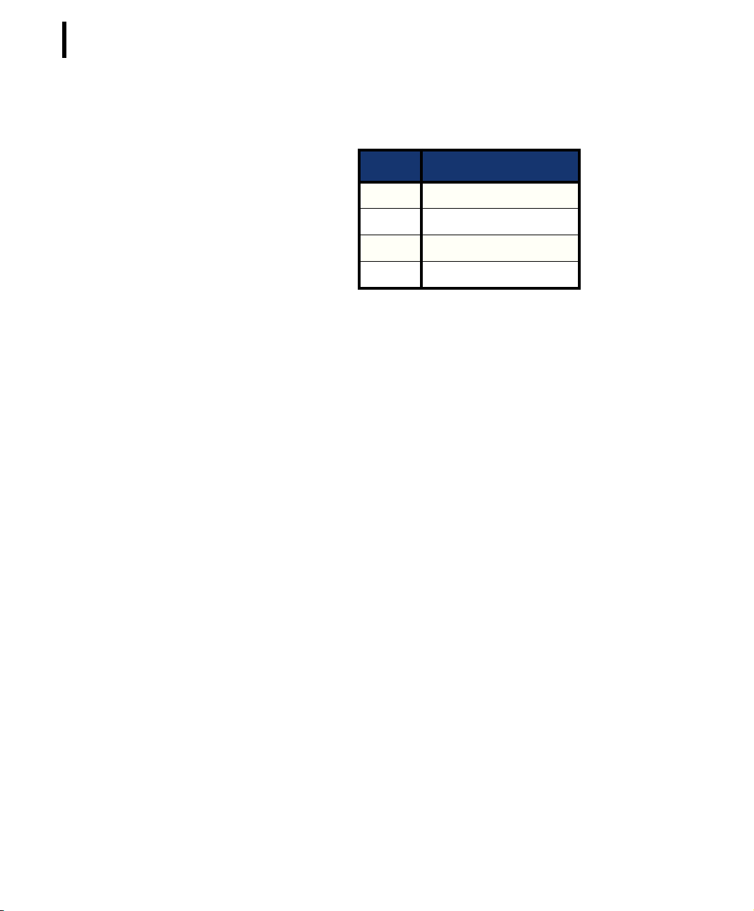
Following notification types can be returned when issuing the
RNTTL command:
Value Notification Type
00 Notify On Positive Threshold.
01 Notify On Negative Threshold.
10 Notify if Out of Limits.
11 Notify if Inside the Limits.
RETURNS The return result depends on the control byte (see table). However,
whatever the return result is, it includes the control byte.
REMARKS The general behavior is that an ANLG command issued on a cer-
tain input channel will override any previous ANLG commands
affecting that channel.
REMOTE The A723 device cannot issue ANLG commands remotely, but can
execute them.
EXAMPLE For RSM
For SSMAA (on channel 4)
For DAN (on channel 0)
For RNTTL (on channel 2)
For ENOPTR (on channel 10)
COMMAND PORT
ANLG 0
9999 ANLG 0 5 5 5 5 5 5 5 5 4 4 5 5 0
#
ANLG 68
9999 ANLG 68 0
#
ANLG 160
9999 ANLG 160 0
#
ANLG 178
9999 ANLG 178 340 3900 0
#
ANLG 202 1000
9999 ANLG 202 0
#
Page 47

CHAPTER 4
Using terminal commands
APPLIES TO A720B and A723, but see also the comments in “Remote” on
page 49.
DESCRIPTION A complex command acting upon the I/O ports of a device.
PARAMETERS A control byte specifying the command, the bit of the port the
command is acting on, and two 16-bit parameters, depending on
the control byte; for some commands, one or both of them may be
missing. However, if they are needed for a certain command but
not given, null values are implied.
The control byte’s significance is shown in Figure 14.
47
Command Code
Figure 14. Control Byte Layout
Port Number
• The Port Number selects a the port that will be affected by
the command. For the A720/A723, only 0000 and 0001 are
accepted.
• The Command Code specifies the operation that will be
applied to the selected port.
Table 5 shows the command codes definitions.
Table 5. Command Code Definitions
Code Description Parameters Returns
0000 RDP – Read Data Port. This command reads the
whole 16-bit port and returns its value; the Port
Number has no significance for this command.
0001 RDDR – Read Data Direction Register. This com-
mand reads the whole 16-bit Data Direction
Register and returns its value; the Port Number
has no significance for this command.
0010 CAI – Configure the port specified by Port Num-
ber as input (acts upon the Data Direction Register).
None A 16-bit integer and the
result (OK or ERROR).
None A 16-bit integer and the
result (OK or ERROR).
The port number. Result (OK or ERROR).
0011 CAO – Configure the port specified by Port
Number as output (acts upon the Data Direction
Register).
The port number. Result (OK or ERROR).
Page 48

CHAPTER 4
48
Performing Advanced Functions
Table 5. Command Code Definitions (Continued)
Code Description Parameters Returns
0100 RBV – Read the specified bit. The port number. Bit value and the result
(OK or ERROR).
0101
0110 DNOPC – Disable Notify On Port Change. The port number. Result (OK or ERROR).
0111 ENOPC – Enable Notify On Port Change. The port number. Result (OK or ERROR).
1000 RPNNER – Read the Pending Notifications and
1001 CB – Clear the specified bit. The port number. Result (OK or ERROR).
1010 SB – Set the specified bit. The port number. Result (OK or ERROR).
1011 XB – Exclusive Or the specified bit. The port number. Result (OK or ERROR).
1100 MFR – Monostable function, start with the speci-
1101 MFS – Monostable function, start with the speci-
RNS – Read the notificationa status. If no notification was pending, this command should
return an error. If one was pending, the notification is cleared.
the Notification Enable Register. This command
returns the 16-bit Pending Notifications and the
Notification Enable Registers; the Port Number
has no significance for this command.
fied bit in OFF state (reset).
fied bit in ON state (set).
The port number. Returns the time of the
last port change in standard time format and the
result (OK or ERROR).
None. Two 16-bit integers (first
the PN and then the NE
register) and the result
(OK or ERROR).
The port number,
the OFF and the
ON times (in seconds), both as 16bit integers.
The port number,
the OFF and the
ON times (in seconds), both as 16bit integers.
Result (OK or ERROR)
Result (OK or ERROR).
1110 MVFR – Multivibrator function, start with the
specified bit in OFF state (reset).
1111 MVFS – Multivibrator function, start with the
specified bit in ON state (set).
The port number,
the OFF and the
ON times (in seconds), both as 16bit integers.
The port number,
the OFF and the
ON times (in seconds), both as 16bit integers.
Result (OK or ERROR).
Result (OK or ERROR).
Page 49

CHAPTER 4
Using terminal commands
a. See also “Notifications” on page 53.
RETURNS The return result depends on the control byte. However, whatever
the return result is, it includes the control byte.
REMARKS The general behavior is that a PORT command issued on a certain
port bit will override any previous PORT commands. For example,
if a port was configured as input and then an MFR (monostable
function) was issued, the port automatically switches to output. A
new MFR or similar function clears the status of the port and starts
from scratch, even if the previous command was not finished.
REMOTE Yes, for the A720 and A723. If you are using a terminal window for
the A720, you cannot issue the PORT command. If you are using a
terminal window for the A720B, you can issue a PORT command
remotely for an A720 or A723 RTU, but you cannot issue the command for the A720B receiver. In other words, the base station can
issue a remote command for an RTU, but it cannot issue such a
command for itself. An RTU cannot issue the command at all, but
can execute it. An axcpetion is the A723 RTU that accepts this
commands also over the serial line.
49
EXAMPLE For RDP:
6789 PORT 0
6789 PORT 0 1 0
#
For RDDR:
6789 PORT 16
6789 PORT 16 0 0
#
For ENOPC:
6789 PORT 112
6789 PORT 112 0
#
For RPNNER:
6789 PORT 128
6789 PORT 128 0 1 0
#
Page 50

CHAPTER 4
50
Performing Advanced Functions
For RNS:
6789 PORT 80
6789 PORT 7/5/1999 18:34:22 0
#
COMMAND RX
APPLIES TO A720, A720B, A723
DESCRIPTION Switches the unit to permanent receive mode (for tuning pur-
poses).
PARAMETERS None.
RETURNS Nothing.
REMARKS The system stops, and exits the command only when you press a
key. This command returns no message.
REMOTE No.
EXAMPLE RX
193 RX 0
#
COMMAND TX
APPLIES TO A720, A720B, A723
DESCRIPTION Switches the unit to transmit mode (for tuning purposes).
PARAMETERS None (sends an unmodulated carrier), 1 (sends a 1 kHz modulated
carrier), 0 (sends a 2 kHz modulated carrier) or 5 (sends a mixed 1 +
2 kHz modulated carrier).
RETURNS Nothing.
REMARKS The system stops, and exits the command only when you press a
key. This command returns no message.
REMOTE No.
EXAMPLE TX
193 TX 0
#
Page 51

CHAPTER 4
Using terminal commands
TX 1
193 TX 0
#
TX 5
193 TX 0
#
COMMAND B
APPLIES TO A720, A723
DESCRIPTION Sends a broadcast frame.
PARAMETERS None.
RETURNS A data block.
REMARKS After the device sends the broadcast frame, it will listen for
answers. All valid answers will be listed with their IDs.
REMOTE Yes, but only for the A723. A remote broadcast command instructs
the remote to issue a broadcast (the remote must support this
function). A subsequent BLST command retrieves a list of stations
that the remote heard after issuing the broadcast frame.
51
EXAMPLE B
6789 B 0
#234 BA 0
#7851 BA 0
15190 B
15190 B 0
#
COMMAND BLST
APPLIES TO A723
DESCRIPTION Retrieves a list with stations heard after the last broadcast com-
mand.
PARAMETERS None.
RETURNS A data block.
REMARKS None.
Page 52

CHAPTER 4
52
Performing Advanced Functions
REMOTE Yes (the remote must support this function).
EXAMPLE BLST
6789 BLST 30/8/2001 16:03:41 4
15190 255 255
2419 255 201
10836 247 187
10805 255 187
0
#
15190 BLST
15190 BLST 30/8/2001 16:03:41 6
15193 255 0
7852 255 0
14640 255 0
2419 255 0
9476 255 0
10836 255 0
0
#
COMMAND VER
APPLIES TO A720, A720B, A723
DESCRIPTION Requests the firmware version of the device.
PARAMETERS None.
RETURNS The current version.
REMARKS GET only.
REMOTE No.
EXAMPLE VER
234 VER 1.3 0
#
VER
6789 VER 2.0 0
#
Note: This command is provided only for compatibility with older
units. The software may use this command to identify the
Page 53

Notifications
CHAPTER 4
Notifications
unit it is communicating with. After detecting that the device
supports this protocol, the INFO command must be used for
further details.
Notifications are frames sent asynchronously by devices that are
otherwise slaves. The notifications are received by a device closest
to the host and then sent to the host. If the host is not available,
the receiving device will store the notification and wait until it is
questioned by the host. At this point, it will inform the host that it
has a notification. It is then the task of the host to issue a command
to read the respective notification.
Before a device can issue a notification, the notification must first
be enabled. Special frames are used to this end, depending on the
notification type. If an end device is not able to send a notification
due to radio propagation or other kind of communication problems, it will store the date/time when the notification took place.
As soon as the communication is re-established, the device will try
to send the notification again.
53
Note: To avoid collisions, the device will wait a random time (up to
10 seconds) before sending the notification frame.
When the device closest to the host receives a notification from a
remote, it must inform the host about it by sending a break character on the serial line. The host must then issue the command DEV
in order to see which device has a notification pending (see also
“DEV” on page 35). If the host is not available, the device closest
to the host will wait until first time requested by the host and after
answering to the host request will re-send a break. This sequence
will go on as described until the host issues the DEV command.
The following notification is currently defined for the A720 device:
• NOPC—Notification On Port Change (see “PORT” on
page 46).
In addition to this notification, the A723 devices can issue the following:
• NOTR—Notification On Threshold Reached (see “ANLG” on
page 43)
The A720B device does not currently recognize notifications.
Page 54

CHAPTER 4
54
Performing Advanced Functions
Returned errors list
Following are error messages you might get.
Command line interpreter
•1 — nonexistent command
•2 — command line buffer overflow (input line too long)
•3 — internal error
•4 — reserved
•5 — missing or false parameters in command
•6 — operation not implemented
Device descriptors and storage handler
• 10 — device not found (attempt to perform a command on a
nonexistent device)
• 11 — device already exists
• 12 — reserved
• 13 — no more space for descriptors (too many devices)
• 14 — no more records for the specified device
• 15 — temporary communication break, no more data (the last
request was not successful)
• 16 — time-out (the handler blocked or is busy)
• 17 — internal error
• 18 — attempt to insert a reserved device ID number (0 or
65535)
Real time clock
Radio interface
• 20 — incorrect time supplied (conversion to time_t was not
possible)
• 30 — error at receive (CRC, etc.)
• 31 — unexpected frame received
• 32 — wrong length
• 33 — reserved
• 34 — reserved
• 35 — time-out (remote device not responding)
Page 55

Notifications
CHAPTER 4
Returned errors list
• 36 — receiver busy (for example, just making the request
round)
• 40 — request to read a notification when no notification is
pending
55
Page 56

CHAPTER 4
56
Performing Advanced Functions
Page 57

Appendix. Specifications
57
The A720 series was intended to fulfill the specification of the ETSI
300 220, Class I, Subclasses a and b, but other national norms are
similar to this (for example, the CFR 47, Part 90, Subpart J). Table 6
shows the main operational parameters of the A720 series.
Table 6. Operational Parameters
Parameter Min Typ Max Unit
Common
Supply 5.0 6.2 10.0 V
Operating Temperature -30 +70 °C
Relative Humidity 10 99 %
Class Protection IP65
Data Rate (using the onboard software modem) 1000
Operating Frequency (low band version)
Operating Frequency (high band version)
Frequency Stability (-20 to +60 °C)
Frequency Stability (-30 to +70 °C) ±2.5 kHz
b
b
432 450 MHz
450 470 MHz
150
a
2000 bps
±
1.5
kHz
Page 58

58
Table 6. Operational Parameters (Continued)
Parameter Min Ty p Max Unit
Receiver
Sensitivity (10 db S/N) -93 (A720)
Image Frequency Attenuation (1st IF = 45 MHz) 35 dB
Local Oscillator Leakage 2 nW
Adjacent Channel Attenuation (both versions) 55 dB
RSSI Dynamic 90 dB
Operating Current (incl. onboard microcontroller)
Transmitter (all measurements made on a 50 Ω resistive load)
Output Power 7 9 10 dBm
Spurious Radiation (0 to 862 MHz) 2 nW
Spurious Radiation (862 MHz to 3.5 GHz) 200 nW
dBm
-105(A723)
c
15 mA
Adjacent Channel Power (12.5 kHz version) -32 dBm
Adjacent Channel Power (25 kHz version) -44 dBm
Occupied Bandwidth (12.5 kHz version) 8.5 kHz
Occupied Bandwidth (25 kHz version) 15 kHz
Operating Current (incl. onboard microcontroller) 50 mA
A720/A723 only
Analog Inputs 0 2.5 V
Analog to Digital Converter Resolution 8 (A720)
10 (A723)
Digital Inputs V
Digital Inputs V
il
ih
Pulse Counter Input Frequency
2.5 V
d
0.5 V
1.5 Hz
Pulse Counter Resolution 8 (A720)
16 (A723)
Digital Outputs Sink/Source 2 mA
Digital Outputs V
Digital Outputs V
ol
oh
2.9 V
0.3 V
bits
bits
Page 59

CHAPTER
a. Data rate is content dependent.
b. This parameter represents the tuning range; the switching range may be limited in
the software to a narrower space (even to the extent of a single channel).
c. Continuous duty.
d. Electrical levels are the same as for the Digital Inputs.
59
Page 60

60
CHAPTER
Page 61

Index
61
A
A720 description, 5
A720B description, 5
about the LED, 16
ANLG, 43
answer format, 25
B
B
series 1, 30
series 2, 51
base station
composition, 9
graphic, 12
installation issues, 10
packaging, 9
battery
changing, 19
description, 17
operation, 18
BLST, 51
C
changing the battery, 19
CMDS, 30
command
ANLG, 43
B
series 1, 30
series 2, 51
BLST, 51
CMDS, 30
DATA, 36
DEL, 36
DEV, 35
DUMP, 29
FDEV, 41
format, 25
FREQ
series 1, 28
series 2, 31
ID, 32
IMME, 40
Page 62

62
INDEX
INFO, 41
OWNID, 26
PMP
series 1, 27
series 2, 33
PORT, 46
query parameters, 29
REPL, 35
ROUTE, 40
RSSI
series 1, 28
series 2, 31
RX
series 1, 29
series 2, 50
SLOT
series 1, 27
series 2, 32
SST, 34
TIME, 30
TX, 50
VER
series 1, 29
series 2, 52
XMIT, 29
command line interpreter errors, 54
configuring
addIT RTU in addVANTAGE software, 17
addVANTAGE Lite software, 12
devices, 24
connectivity check, 14
connector
definition, 22
receiver, 22
RTU, 23
conventions, document, 7
D
DATA, 36
DEL, 36
DEV, 35
device
configuration, 24
descriptors and storage handler errors, 54
determining version, 22
operation time, 18
document conventions, 7
DUMP, 29
E
errors
command line interpreter, 54
device descriptors and storage handler,
54
radio interface, 54
real time clock, 54
F
FDEV, 41
field installation, RTU, 15
formats, 25
FREQ
series 1, 28
series 2, 31
I
ID, 32
IMME, 40
INFO, 41
install
power supply, 11–12
receiver, 11
RTU, 14
installation issues, 6
internal battery, 17
introduction, 5
L
LED
definition, 14
usage, 16
Page 63

INDEX
63
M
maintaining the RTU, 17
N
NOPC, 53
notification
definition, 53
NOPC, 53
O
overview, 5
OWNID, 26
P
packaging
base station, 9
RTU, 13
performing a connectivity check, 14
placing a base station, 10
PMP
series 1, 27
series 2, 33
PORT, 46
power supply
graphic, 11
installing, 11–12
Q
querying command parameters, 29
remote transmission unit. See RTU
REPL, 35
restrictions for installation, 6
ROUTE, 40
RSSI
series 1, 28
series 2, 31
RTU
connector, 23
field installation, 15
graphic, 14
installing, 14
mainenance, 17
packaging, 13
use, 13
RX
series 1, 29
series 2, 50
S
series, determining, 22
SLOT
series 1, 27
series 2, 32
software configuration, 12, 17
SST, 34
T
TIME, 30
TX, 50
R
radio interface errors, 54
real time clock errors, 54
receiver
connector, 22
graphic, 10
installing, 11
U
using
LED for connectivity check, 14
RTU, 13
V
VER
series 1, 29
series 2, 52
Page 64

INDEX
64
W
what a base station contains, 9
X
XMIT, 29
Page 65

Credits and Colophon
65
Credits
Development
Günther Leber , Lix N. Paulian, Florin Wacykiewcz, Matthias Wallner .
Documentation and artwork
Dimi Everette, Stefan Hasegan, Lix N. Paulian.
Quality control and testing
Steve Grove, Martin Hackl, Bernd Hartmann, Günther Leber , Lix N.
Paulian, Matthias Wallner.
Colophon
This manual was written and produced with Adobe FrameMaker
on the MacOS platform. The illustrations were done or prepared in
Adobe Illustrator and Adobe Photoshop on a Power Macintosh.
Some illustrations were done in Corel Draw! on Microsoft Windows. The electronic version was created with Adobe Distiller on a
Power Macintosh.
Page 66

66
 Loading...