

Page 1
&
s,a.f.e:
HIGH CURRENT, MULTI-CHANNEL
POWER AMPLIFIERS
Page 2

GFA-7705/07 Features
• Precision-matched devices used throughout the signal path.
• Independent power supplies for each channel.
• Fewer gain stages improve signal reproduction accuracy.
• Custom toroidal power transformer provides better regulation and greater peak current capability.
• ADCOM-Universal pre-prepped chassis and internal power supplies for easy in-field upgradeabiiity
from 5 to 7 channel configuration.
• Independent thermal-overload and distortion LEDs for ail 5 (to 7) channels.
• S.A.F.E.® Circuit: Self Annealing Fuse Equipped-automatic reset protection circuit in the event of
speaker or speaker wire dead-short.
• High quality, gold-plated 5-way binding posts.
• High quality, gold-plated RCA jacks.
• Large independent, internal heatsinks for greater cooling capability of output devices.
. Convenient 12 VDC power ON/OFF triggering.
• Heavy gauge, anodized aluminum front panel.
• Coolir^ vents for greater efficiency and cooler operation while driving low impedance loads.
Table of Contents
Introduction
Warranty Information....................................................................................................................4
Description of Unit— 20-Amp Device Notification............................................4
Rear Panel................................................................................................................................... 5
Front Panel.................................................................................................................................. 7
Installation & Hookup
Unpacking the GFA-7705/07........................................................................................................
Placement of the GFA-7705/07......................................................................................................9
Quick Connection Diagram.......................................................................................................... 10
Connecting the GFA-7705/07........................................................................................................ 11
Caring for your GFA-7705/07......................................................................................................... 12
Troubleshooting
Resolving Problems.....................................................................................................................13
Service Information...................................................................................................................... 14
Specifications.............................................................................................................................. 15
9
Page 3

introduction
Congratulations on your decision to purchase the GFA-7705/07 multi-channel power amplifier. The GFA-7705/
07 integrates very well with any other home theater system, such as Dolby ProLogic™ or Dolby Digital™. You
have made a wise choice that vdll reward you with exceptionally accurate and musical sound reproduction for
years to come. To realize the full potential of your new amplifier, please read these operating and installation
instructions thoroughly before attempting to make any connections to it.
ADCOM Protection Plan (NORTH AMERICA ONLY)
ADCOM offers the enclosed valuable Limited Warranty. Please read the details on the Warranty Card carefully
to understand the extent of the protection offered by the Warranty, its reasonable limitations, and what you
should do in order to obtain its benefits. Be sure to verify that the serial number printed on the rear panel
matches the serial number on the outer carton. If any number is altered or missing, you should notify us
immediately in order to ensure that you have received a genuine ADCOM product which has not been opened,
mishandled, or tampered with in any way. Always retain your original sales receipt as a proof of purchase.
Description of Unit
The GFA-7705/07 is a 20-Amp Device.
The GFA-7705/07 is high-power, high-current, wide-bandwidth design employing ADCOM’s Fast Analog Transform
(F.A.T.) circuitry with direct-coupled Power Rig output stages. All channels are completely monaural from
transformer secondaries through the output stages.
In order for this product to achieve its actual rated power output on all channels and to avoid repeatedly
throwing/popping the related electrical service panel circuit breaker, it is critical that the amplifier be
professionally installed on a 20-Amp household AC circuit and outlet, preferably dedicated but at minimum one
not shared with other large current-draw appliances or devices.
Common 15-Amp household circuits are easily and inexpensively converted to 20 Amp configuration by any high-
voltage licensed electrician.
For this reason, the GFA-7705/07 ships Factory-equipped vrith a hard wired, 20-Amp Plug on the AC Power Cord.
WARNING: DO NOT DEFEAT THE 20-AMP PLUG OR HARDWIRED AC POWER CORD TO EAAPLOY EITHER A 15 AMP
OUTLET OR “AUDIOPHILE” TYPE DETACHABLE POWER CORD.
DOING SO WILL VOID PRODUCT WARRANTY. MAY DAAAAGE THE PRODUCT AND PLACE THE USER AT EXTREME RISKOF
INJURY OR DEATH.
Page 4
(3a) (3b) (4)
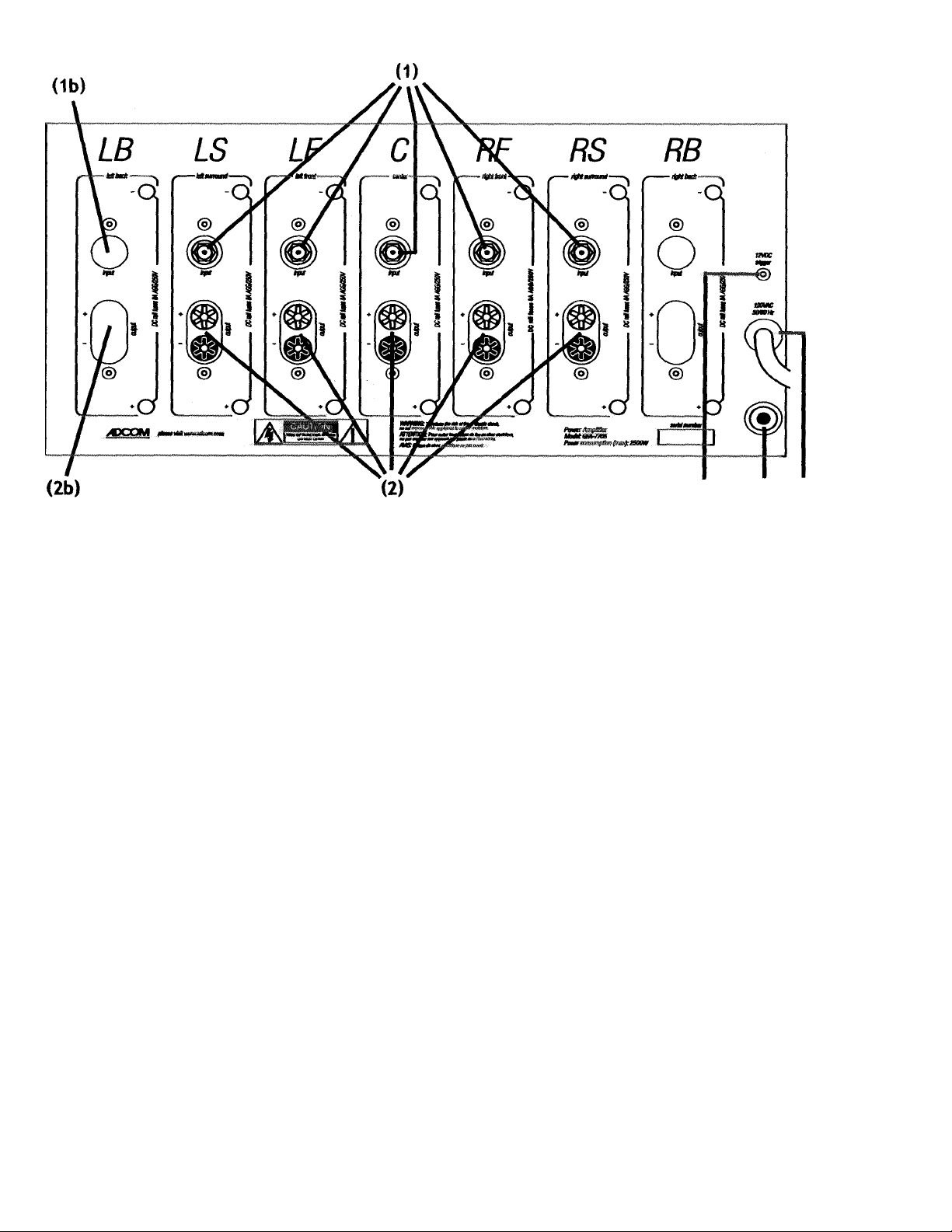
Rear Panel
Inputs (1)
The audio inputs for the GFA-7705 and 7707 are through high-quality, gold-plated RCA jacks to minimize highfrequency losses, rw)ise, etc. They will accept standard RCA-type plugs, one for each of the five channels; Front L
(Left), Center, Front R (Right), Surround L (Left), and Surround R (Right). To insure that the performance designed
into the GFA-7705/07 is preserved, you should use the highest quality, shielded audio cables possible. There are
many cables which are color-coded and specifically designed for this application. Your Adcom dealer can help
select the best cable for your needs. (See Connecting the GFA-7705/07 for more information.)
Inputs (1b)
Chassis knock-out for future expansion channel-card input jack (GFA-7705 only).
Outputs (2)
The GFA-7705/07’s connections to the loudspeakers are made through high-grade, 5-way, gold-plated binding post
terminals. There are two terminals for each speaker, which are colored RED for the positive (+) output and BLACK
for the negative (-) output.
The binding posts will accept a variety of connector types; the most secure and prevalent of these is the “U”-type
spade connectors (at least 0.25” wide and maximum width of 0.57”). The terminal will also accept bare wire (up
to AWG10) and “banana” type plugs (single or dual).
(See CONNECTING THE GFA-7705/07 for more information.)
Outputs (2b)
Chassis knock-out for future expansion channel-card output binding posts (GFA-7705 only).
Page 5

WARNING
THERE ARE NO USER-SERVICEABLE PARTS OR FUSES INSIDE THE GFA-7705/07. In the event that the
amplifier’s rear-panel circuit breaker fails to reset (opens again v/hen power applied to unit and unit
turned on) you must refer the amplifier to ADCOM Factory Service or ADCOM Authorized Service Center.
Do not open the amplifier nor remove the topcover-Hazardous and Potentially Lethal Voltage Present
and Warranty may be voided.
12VDC Triggering (3a)
ADCOM has provided the installer the ability to control the OFF/ON function of the GFA-7705/07 by a
12Volt DC output jack on the rear of certain pre-amplifiers and tuner pre-amplifiers. When using this
feature the front panel Power Switch must be left in the in “on" position. To connect, you will need a
monaural mini phone plug to monaural mini phone plug cable of appropriate length (not included) to
reach from the rear panel of the amplifier to the rear panel of the pre-amplifier. Contact your dealer
for information on using this feature wnth ADCOM and other brand pre-amplifiers. Although 12VDC is
optimal, the circuit will operate from approx. 5 to 30VDC. Center conductor (tip) is positive (+).
AC Circuit Breaker (3b)
The 15-Amp AC Breaker protects the electronic circuits of the GFA-7705/07. Normally, this breaker vdll
open only if there is an overload or a component failure within the GFA-7705/07.
If the Power LED (7) does not glow, it may be an indication that the AC Breaker has blown. If you are
using the 12VDC Triggering feature (above) it may be possible that there is no trigger voltage present or
a problem exists with that connection.
To determine if the problem is caused by a malfunction in the 12VDC system, remove the small plug
inserted into the 12VDC Triggering jack. Press the front panel power switch to turn off the amp, and
immediately re-press the power switch. If the problem is caus^ by the 12VDC triggering circuit the
amp will turn on and the LED will glow.
DO NOT attempt repair of the 12VDC system. If you are not sure, or the amplifier displays other
symptoms, please consult the RESOLVING PROBLEMS section on page 13.
AC Power Cord (4)
The AC cord provides power to operate all the GFA-7705/07’s circuits. The GFA-7705/07 is a very high
power amplifier and as such must be directly connected to the wall outlet or an appropriate (noncurrent limiting) surge protector or AC line conditioner of 20-Amp service capability.
NOTE: As previously described on Page 4, the attached plug is a 20-Amp fitting which, in order for the
amplifier to deliver its rated power output, should not be defeated in order to accomodate standard
15-amp household vrall outlets.
Please consult vdth your dealer and/or licensed electrician for conversion of a 15 amp outlet and panel
circuit to a 20 amp circuit.
Page 6

Front Panel
On/Off Switch (5)
The On/Off Switch controls power to the power transformer and circuits of the GFA-7705/07.
Whenever the GFA-7705/07 is energized the Power LED (7) will glow. To turn the GFA-7705/07 on,
press the push-button. It will remain in the “engaged” position while the unit is energized. To turn the
GFA-7705/07 off, press the push-button in and release and it will move to the “disengaged” position.
Power LED (6)
This LED will glow when the On/Off Switch (5) is turned on and the GFA-7705/07 is energized. The
Power LED indicates that there is AC voltage being fed to the amplifier, but it does not signify that all
the amplifier's circuits are in operation. If, for example, one of the Thermal Protection LED (8) glows,
that amplifier channel will not produce sound even though the Power LED may still glow. When the GFA-
7705/07 is turned off, the Power LED will take some time to fade out completely. It may take up to 30
seconds to fully extinguish.
NOTE: Whenever a 12 Volt trigger connection is made to the GFA-7705/07, the Power LED will not
illuminate, whether the On/Off Switch is pressed in or not, imtil a 12V signal is present from the
triggering, source product. Please refer to Section 3a, 12VDC Triggering.
Page 7

Distortion Alert LEDs (7)
The Distortion Alert circuit is a unique ADCOM distortion detection system which reads all forms of non
linear distortion such as THD, IM, slew-induced, “clipping,” etc. The Distortion Alert LEDs will light
when distortion reaches approximately 1% regardless of impedance, voltage/current phase angle or the
reactance of the loudspeakers which the amplifier is driving. Sometimes, when the amplifier is in use, the
LEDs may occasionally flicker during high volume listening, particularly if you are driving low impedances.
This flickering is no cause for concern. The LEDs are simply warning you that the amplifier is approaching
its maximum power output into the particular loudspeakers you are using.
If, however, the Distortion Alert LEDs glow brightly or are illuminated most of the time during playback,
you are over driving the amplifier and should turn down your volume control to reduce the listening
level, otherwise it may cause the Thermal Protection to be activated or, in extreme cases, damage vour
loudspeakers.
Thermal Protection LEDs (8a)
The GFA-7705/07 is provided with both a thermal protection circuit and a current overload circuit
which vrill shut down the individual amplifier’s channels if its heatsink temperature reaches 85°C or the
amplifier’s outputs are shorted. The Thermal Protection LEDs will light when either of these protection
circuits are on its respective channel has been triggered and the amplifier is inoperative. The thermal
protection circuitry will typically be triggered by very high power demands into impedances much
lower than the amplifier is capable of driving at those levels.
If any amplifier channel’s output through the loudspeaker(s) ceases abruptly, and its Thermal Protection
LED glows, you will know that its heatsink temperature has become unacceptably high and the circuitry
is protecting the amplification devices. Please note that the Power LED (7) vrill remain on and the
amplifier will still be energized. Once the temperature of the heatsink(s) drops to a safe operating
level, that amplifier will automatically resume operation.
Activation of the Thermal Protection circuitry in any of the amplifiers in the GFA-7705/07 is an
indication that the amplifier has been over driven or that the load the loudspeakers are presenting to
the amplifier is unreasonably low. If you wish to prevent recurrent activation of the thermal protection
circuitry, you must reduce the volume-level demands or correct the load-impedance condition which
may be causing activation of this circuitry.
S.A.F.E.® Protection Circuit (8b)
Self-Annealing Fuse Equipped: Instead of blowing internal protection rail fuses in the event of a dead-
short to either a loudspeaker or speaker cable leads, the GFA-7705/07 will enter into a self-protect
SAFE mode.
If the output of any channel of the amplifier becomes shorted the protection circuit vrill trip and
the individual Thermal Protection LED for that channel will light. The Protection LED will blink
approximately every 5 seconds as the circuit vrill attempt to reset; if the short has been corrected the
amplifier vrill resume proper operation. If the short is still present the channel vrill cycle off again.
The cycling of the protection circuit vnll continue until the short is corrected or the amplifier power is
switched off.
Page 8

WARNING
Whenever connections to or from the GFA-7705/07 are being made, be certain that the AC On/Off Svdtch
(5) of the amplifier is in the OFF position, the AC Power Cord (4) of the amplifier is disconnected from the
AC wall outlet and that all associated components are turned off.
Installation & Hookup
Unpacking the GFA-7705/07
Before your new GFA-7705/07 left our factory, it was carefully inspected for physical imperfections and
tested for all electrical parameters as a routine part of ADCOM’s systematic quality control. This, along
with full operational and mechanical testing, should ensure a product flawless in both appearance and
performance. After you have unpacked the GFA-7705/07 inspect it for physical damage. Save the shipping
carton and all packing material as they are intended to reduce the possibility of transportation damage,
should the amplifier ever need to be shipped again. In the unlikely event damage has occurred, notify your
dealer immediately and request the name of the carrier so a written claim to cover shipping damages can
be initiated. THE RIGHT TO A CUIM AGAINST A PUBLIC CARRIER CAN BE FORFEITED IF THE CARRIER IS NOT
NOTIFIED PROMPTLY IN WRITING AND IF THE SHIPPING CARTON AND PACKING lAATERIALS ARE NOT AVAILABLE
FOR INSPECTION BY THE CARRIER. SAVE ALL PACKING AAATERIALS UNTIL THE CLAIM HAS BEEN SETTLED.
Placement of the GFA-7705/07
During normal home operation the internal heatsinks of the GFA-7705/07 may become warm. However,
there are instances during hi^-level playback into low impedances when the heatsinks will become much
warmer than usual. To ensure the amplifier’s long-term, trouble-free operation, it is necessary to provide
adequate ventilation for the heatsinks. Therefore, the GFA-7705/07 should be kept away from external
sources of heat such as radiators and hot-air ducts. The GFA-7705/07 should never be placed with other
heat-producing components in a cabinet or enclosure lacking free air flow. The top and bottom panels
of the amplifier’s chassis have been provided with vents to allow the necessary cooling of the internal
components. It is imperative that these vents are not obstructed in any way.
We recommend that you do not stack other components on top of the GFA-7705/07. Not only will heat
generated by the amplifier affect the performance of equipment stacked on top of the GFA-7705/07,
but the free flow of air through the ventilating slots in the amplifier may be partially obstructed. This is
particularly important if your system includes low-impedance loudspeakers which are difficult to drive, or
you will consistently demand high volume levels from the amplifier and speaker system.
If you observe these recommendations, the GFA-7705/07 will perform reliably in any reasonable
environment. You should also pay attention to such normal considerations as protection from excessive
dust and moisture. Occasional vacuuming of accumulated dust on the chassis, panels and around the
ventilating slots should be all that is required.
The optimal performance of your new GFA-7705/07 will ultimately depend on the care with which you
make the connections between the amplifier, preamplifier, surround sound decoder and the loudspeakers.
All input and output signal connections should be made only with high quality, low capacitance, shielded
cables follovnng the recommendations in the Inputs and Outputs section of CONNECTING THE GFA-7705/07.
Quick Connections
For those of you who are in a hurry to hook up your amplifier into your system, we have included this
quick-connection section. The wiring is straight forward and expeditious if you use the proper cables
and follow this diagram exactly. If you have any difficulties or questions, please refer to the appropriate
section of this manual for complete descriptions and instructions.
Page 9

left surround A'
speaker H'
A riqht surround
V speaker
Connecting the GFA-7705/07
Remember, that the Left and Right designations are as you are sitting down in your listening/viewing area.
On the rear panel, the inputs and outputs are grouped in 5 or 7 bracketed sets, one set for each channel.
They are as follows:
LB - Left Back (GFA-7707 only)
LS — Left Surround
LF — Left Front
C — Center
RF — Right Front
RS — Right Surround
RB - Right Back (GFA-7707 only)
10
Page 10

Inputs (1)
To preserve the correct effects, be certain to connect the RCA cables to the proper RCA-input
connector. If the cables are color coded, then use this sequence for the connections:
Blue.......................................................................................... Left Front
Red...........................................................................................Right Front
Green...............................................................................................Center
White with Blue Stripe...........................................................Left Surround
White with Red Stripe.......................................................... Right Surround
The recommended maximum RCA cable capacitance should be less than or equal to 30pF per foot
when measured between the two conductors, and less than or equal to 50pF per foot >^en measured
between one conductor and the shield.
Outputs (2)
КОТЕ: The GFA-7705/07 is “polarity correct”. That is, it does not invert phase from input to output.
Any positive signals at its inputs will appear as a positive signal at its outputs.
In connecting the amplifier to the loudspeaker, it is vital to maintain proper polarity (positive to
positive, negative to negative). On the GFA-7705/07, the positive terminal is color coded RED and
labeled “+,” and the negative is color coded BLACK and labeled
The positive terminal on the corresponding loudspeaker will be color coded RED, or will be labeled “+,”
“pos,” “positive,” “8 ohms,” or “4 ohms.” The negative terminal on the speaker will be color coded
BLACK, or will be labeled “neg,” negative,” “C,” “Common,” “G,” or “grourtd.”
It is necessary that your speaker cables be terminated with “U”-type spade connectors. These will give
the most contact area insuring long-term reliability. The spade
connector should have a maximum width of 0.57 inches and an -j
opening width of no less than 0.25” (see diagram on right). —.L
____________________-_______
a2s-ot*i
JL
3
X
To properly connect the speaker cable to the binding posts turn the insulated head of the binding post
clockvrise until the wire or connector is firmly secured. Finger pressure is sufficient and you should not
use pliers or other tools which could damage or over tighten the binding-post assembly. The binding
posts have been designed in such a way that finger pressure is all that is required to cause a “pinching”
action among the different metal surfaces to ensure proper connection.
It is very important to use the correct size of wire in order to avoid unnecessary loss of amplifier power
in the cable, reduction of amplifier damping factor and other undesirable conditions. Recommended
capacitance of the speaker wire should not exceed 50pF per foot. This insures hi^ frequencies will not
be rolled-off.
11
Page 11

It is suggested that the three front channels follow this chart for speaker lengths and wire gauges.
up to 24 feet
up to 36 feet
up to 58 feet
Generally, for the two rear surround channels, longer runs of cable are needed, but since less program
material is being transmitted through the cable, longer runs are acceptable:
up to 48 feet
up to 72 feet
up to 116 feet..............................................................AWG12
If longer runs are needed, it is best to consult with your Adcom Dealer to maximize the performance of
your system with your exact conditions.
All loudspeakers having a nominal impedance down to 4 ohms can be connected to and driven by the
GFA-7705/07. The amplifier can drive these low-impedance speakers at more than adequate power
levels with no difficulty. It should be noted here that many loudspeaker systems which are nominally
rated at 4 ohms drop in impedance, in some parts of their frequency range, to as low as 2 ohms (and
sometimes less). You will not experience difficulties even with these very low impedance loads unless
you demand excessively high volume levels from your system.
It is not recommended that you run additional sets of speakers on any or all of the amplifiers in the
GFA-7705/07 in order to insure the integrity of the system. If you choose to add remote speakers in
another room, it is strongly suggested that a switching system to disconnect the non-home-theater
speakers be incorporated when the surround sound, home-theater mode is in operation. A device
such as the Adcom GFS-300 or GFS-600 Speaker Selector is strongly recommended. A Speaker Selector
enables you to maintain integrity while giving you the flexibility to add speakers throughout your
house.
...............................................................
...............................................................
...............................................................
...............................................................
...............................................................
AWG16
AWG14
AWG12
AWG16
AWG14
CARING FOR YOUR GFA-7705/07
Great care has been taken by ADCOM to ensure that your amplifier is as flawless in appearance as it
is electronically. The front panel is a heavy-gauge, high-grade aluminum extrusion carefully finished
and anodized for durability. The chassis, top cover and rear panel are heavy-gauge steel that has been
powder coated and baked to ensure a lasting finish. If the front panel, top or sides become dusty or
fingerprinted, they can be cleaned with a soft lint-free cloth, slightly dampened with a very mild
detergent solution or glass cleaner.
DO NOT SPRAY OR POUR LIQUIDS OF ANY KIND ON THE GFA-7705/07.
12
Page 12

Troubleshooting
Resolving Problems
Use the chart below to solve common situations that don’t require professional attention. If
the steps stated in POSSIBLE SOLUTION do not resolve your problem, then please contact your
ADCOM Dealer or call the ADCOM Customer Service Department. Any problems not covered
here should be brought to the attention of your ADCOM Dealer or ADCOM Customer Service
Department.
A special note on “hum”: When there is a low-volume “hum” audible throughout your
speakers, even v/ith the main volume turned all the way down, you likely have a common
phenomenon known as “ground loop.” A ground loop is basically a difference in ground
voltages between two or more components which are connected electrically and which
creates multiple current paths where there must only be one. This difference in potential
creates a 60 Hz low-level sound (approximately a low A#), that appears to “hum.”
It can be caused by adding new components to your system, but that does not imply there
is anything electrically wrong with any new component. With the advent of audio/video and
home theater systems, the problem has become commonplace. Generally, the cause is the
Cable-TV incoming signal line. This new incoming line may add an additional ground at a
different potential from the AC line ground of your other equipment.
Sy'iTij,)!. OiTi
Power LED does not glow
No sound
Power LED glows,
but no sound
One channel not
producing sound and/or
Thermal LED Blinking
Hum from all speakers
at any volume
Hum from all speakers
(hum goes up or
dovm with volume)
Hum from the amplifier itself
AC Power Cord (4) not plugged in
AC Breaker (3b) opened
12V Trigger Connected but not activated
Preamp or source unit is not on
Connections in rear are loose
Input (1) or Output (2) connectors
disconnected or loose
Speaker disconnected/ shorted
Internal protection engaged
Ground loop (difference in ground
voltages between components)
Problems with source unit (CD, tape,
etc.) or RCA cables connecting that
source unit to the preamp
Some major appliance, dimmer, halogen or
fluorescent light is creating interference
Plug in AC Power Cord (4)
Reset AC Breaker (3b)
Turn on 12V Source Unit
Make sure whole system is on
Verify all connections on rear of amp
Verify both sets of connections on that
channel
Verify connections at speaker/ cable in
tegrity. Bring to Dealer or Service Center
If cable TV is present (see Note 1)
If cable TV is not present (see Note 2)
Try different source (tuner, tape, etc.)
and/or different RCA cable
AAake sure all appliances, dimmers and
suspect lights are off
Notei: Cable TV systems can sometimes contribute to ground-loop problems which cause "hum.” To determine if
your cable system is the contributing factor, disconnect the Cable-TV incoming signal line (round, 75D) at the wall,
or the first component to which the cable is connected to (i.e. the cable box, or VCR.) If the hum is no longer
present, you must insert a “75Q Ground Loop Isolator” before reconnecting the line. You should check with your
ADCOM Dealer to obtain one. If the "750 Ground Loop Isolator” works only partially or not at all, then please read
Note 2 to complete the troubleshooting procedure.
Note 2: AAake sure that the power amplifier is at least six inches from the Preamp and/or Processor. Usually putting
another component between them is sufficient to minimize the hum. If this does not reduce the hum, turn the
system off and disconnect all Inputs from the amplifier. If the hum still persists, then call your Dealer or Service
Center. If the hum disappears, re-connect one RCA cable at a time to see if the specific cable or component is
responsible. If any or all cables cause the hum to appear, subsitute with replacement cable(s). If hum continues
to persist then the preamp or processor should be evaluated for proper operation by your Dealer or Authorized
Service Center.
13
Page 13

Servicing
ADCOM has a Technical Service Department to answer questions pertinent to the installation
and operation of your unit. In the event of difficulty, please contact us for prompt advice.
Please have the following information readily at hand: the unit’s model and serial numbers,
and dealer from whom it was purchased. If your problem cannot be resolved through our
combined efforts, we may refer you to an authorized repair agency, or authorize return of
the unit to our factory. To aid us in directing you to a convenient service center, it would be
helpful if you indicate which major city is accessible from your home.
Please address mail inquires to:
ADCOM Service
8541 East Anderson Drive
Scottsdale, Arizona 85255
United States of America
www.adcom.com
Phone, Fax or Email inquiries to
Voice: (480) 607-2277
Fax: (480) 348-9876
Monday-Friday
9:00 AM to 5:00 PM MST
service@adcom.com
UNDER NO CIRCUAASTANCES SHOULD YOUR UNIT BE SHIPPED TO OUR FACTORY WITHOUT
PRIOR AUTHORIZATION, OR PACKED IN OTHER THAN ITS ORIGINAL CARTON AND FILLERS.
For fax inquires, please include a return fax or voice number for the reply. When calling or
writing about your GFA-7705/07, be sure to note and refer to its serial number as well as the
date of purchase and the dealer from whom it was purchased. In the event the unit must be
returned to our factory for service, you will be instructed on the proper procedure when you
call or write for a Return Authorization. For warranty coverage, a copy of the original proof
of purchase is required. If you have no original copy, please contact your dealer to obtain a
duplicate copy.
If the original shipping carton and its fillers have been lost, discarded, or damaged, a
duplicate carton may be obtained from our Service Department for a nominal charge.
Always ship PREPAID VIA UNITED PARCEL SERVICE (UPS) OR OTHER APPROVED CARRIER. DO NOT
SHIP VIA PARCEL POST, since the packaging was not designed to withstand rough Parcel Post
handling. FREIGHT COLLECT SHIPMENTS WILL NOT be ACCEPTED UNDER ANY CIRCUMSTANCES.
14
Page 14

GFA-7700/7707 Specifications
Power Rating (To EIA/CEA-490-A Requirements
200 Watts continuous average power per channel into 8 ohms at any frequency between 20Hz and 20kHz
with all channels driven at less than 1% THD.
300 Watts continuous average power per channel into 4 ohms at any frequency between 20Hz and 20kHz
with all channels driven at less than 1% THD.
THD Noise at 200 Watts into 8 ohms (Typical)
20Hz.......................................................................................................................................................0.0086%
1kHz...................................................................................................................................................... 0.0096%
10kHz...................................................................................................................................................... 0.0156%
20kHz...................................................................................................................................................... 0.0201%
THD + Noise at 300 Watts into 4 ohms (Typical)
20Hz.......................................................................................................................................................0.0186%
1kHz
...........
........................................................................................................................................... 0.0214%
10kHz...................................................................................................................................................... 0.0354%
20kHz.......................................................................................................................................................0.0311%
Frequency Response ® 1 Watt into 8 ohms (20Hz to 20kHz)......................................................................... +0, -0.22dB
Power Bandwidth (-3dB)........................................................................................................................ 3 Hz to 130kHz
Dynamic Headroom into 4 ohms........................................................................................................................ 1.90 dB
Signal to Noise Ratio "A” Weighted (200 Watts into 8 ohms)................................................................................ -125 dB
Gain
......................................................................................................................................................................29 dB
Input Sensitivity
for 1 Watt Output................................................................................................................................... 0.1 volts
for 200 Watts Output............................................................................................................................1.40 volts
Input Impedance
Damping Factor (20Hz to 20kHz)..........................................................................................................................> 800
.................................................................................................................................................. 50kO
General
Power (Available in 230VAC on special order)................................................................................ 120VAC - 50/60Hz
Power Consumption (Continuous, All Channels Driven)
Idle (5 Channel).......................................................................................................................................... 120W
Idle (7 Channel).......................................................................................................................................... 170W
200 watts X 5 Ch into 8 ohms......................................................................................................................2200W
200 watts X 7 Ch into 8 ohms......................................................................................................................2700W
Chassis Dimensions (H x W x D).......................................... 8.5” (216mm) x 17” (432mm) x 17.5" (444.5mm)
Maximum Dimensions (H x W x D)
.................................
9 3/8” (238mm) x 17” (432mm) x 18.5” (470mm)
Unit Weight (GFA-7705)................................................................................................................. 69.5 lb. (31.5 kg)
Unit Weight (GFA-7707)................................................................................................................. 78.2 lb. (35.5 kg)
Weight, Packed (GFA-7705)...............................................................................................................81.5 lb. (37 kg)
Weight, Packed (GFA-7707)...............................................................................................................90.4 lb. (41 kg)
Specifications subject to change without notice.
15
 Loading...