

Page 1

®
>DCOM
details you can hear
G FA-5802
High Current MOSFET
Power Amplifier
OWNER’S MANUAL
Page 2
THE FOLLOWING PRECAUTIONS AND SAFETY INSTRUCTIONS
ARE REQUIREMENTS OF UL AND CSA SAFETY REGULATIONS
Warning: To reduce the risk of fire or electric shock, do not expose
this unit to rain or moisture.
CAUTION
RISK OF ELECTRIC SHOCK
A
DO NOT OPEN
A
AVIS: RISQUE DE CHOC ELECTRIQUE-NE PAS OUVRIR
The graphic symbol of a lightning flash with an arrow
point within a triangle signifies that there is dangerous
voltage within the unit and it poses a hazard to anyone
removing the cover to gain access to the interior of the
A
Read all the safety and operating instructions before connecting or using
this unit
Retain this notice and the owner’s manual for future reference
All warnings on the unit and in its operating instructions should be adhered to
All operating and use instructions should be followed
Do not use this unit near water; for example, near a bathtub, washbowl,
kitchen sink, laundry tub, in a wet basement, or near a swimming pool
The unit should be installed so that its location or position does not interfere
with Its proper ventilation For example, it should not be situated on a bed,
sofa, rug, or similar surface that may block the ventilation openings, or
placed in a built-in installation, such as bookcase or cabinet, that may
impede the flow of air through its ventilation openings
The unit should be situated away from heat sources such as radiators, heat
registers, stoves, or other devices (including amplifiers) that produce heat
The unit should be connected to a power-supply outlet only of the voltage
and frequency marked on its rear panel
The power-supply cord should be routed so that it is not likely to be walked
on or pinched, especially near the plug, convenience receptacles, or where
the cord exits from the unit.
Clean unit only as recommended in its instruction manual
The power-supply cord of the unit should be unplugged from the wall outlet
when It is to be unused for a long period of time
Care should be taken so that objects do not fall, and liquids are not spilled,
into the enclosure through any openings
This unit should be serviced by qualified service personnel when
A. The power cord or the plug has been damaged, or
B Objects have fallen, or liquid has been spilled, into the unit; or
C The unit has been exposed to ram, or liquids of any kind, or
D The unit does not appear to operate normally, or exhibits a
marked change in performance; or
E The device has been dropped, or the enclosure damaged
DO NOT ATTEMPT SERVICING OF THIS UNIT YOURSELF.
REFER SERVICING TO QUALIFIED SERVICE PERSONNEL.
unit Only qualified service personnel should make
any such attempt.
The graphic symbol of an exclamation point within an
equilateral triangle warns a user of the device that it is
necessary to refer to the instruction manual and its
warnings for proper operation of the unit
Do not place this unit on an unstable cart, stand, tripod,
bracket, or table The unit may fall, causing serious
injury to a child or adult, and serious damage to the
unit Use only with a cart, stand, tripod, bracket, or table
recommended by the manufacturer, or sold with the
unit Any mounting of the device should follow the man
ufacturer’s instructions, and should use a mounting ac
cessory recommended by the manufacturer
ATTENTION
POUR PREVENIR LES CHOCS ÉLECTRIQUES NE PAS UTILISER
CETTE FICHE POLARISÉE AVEC UN PROLONGATEUR, UNE PRISE
DE COURANT OU UNE AUTRE SORTIE DE COURANT, SAUE SI LES
LAMES PEUVENT ÊTRE INSÉRÉES À FOND SANS EN UISSER AU
CUNE PARTIE À DÉCOUVERT
CAUTION
TO PREVENT ELECTRIC SHOCK DO NOT USE THIS POLARIZED PLUG
WITH AN EXTENSION CORD, RECEPTACLE OR OTHER OUTLET UN
LESS THE BLADES CAN BE FULLY INSERTED TO PREVENT BLADE
EXPOSURE
CAUTION
POWER LINES
Any outdoor antenna must be located away from all power lines.
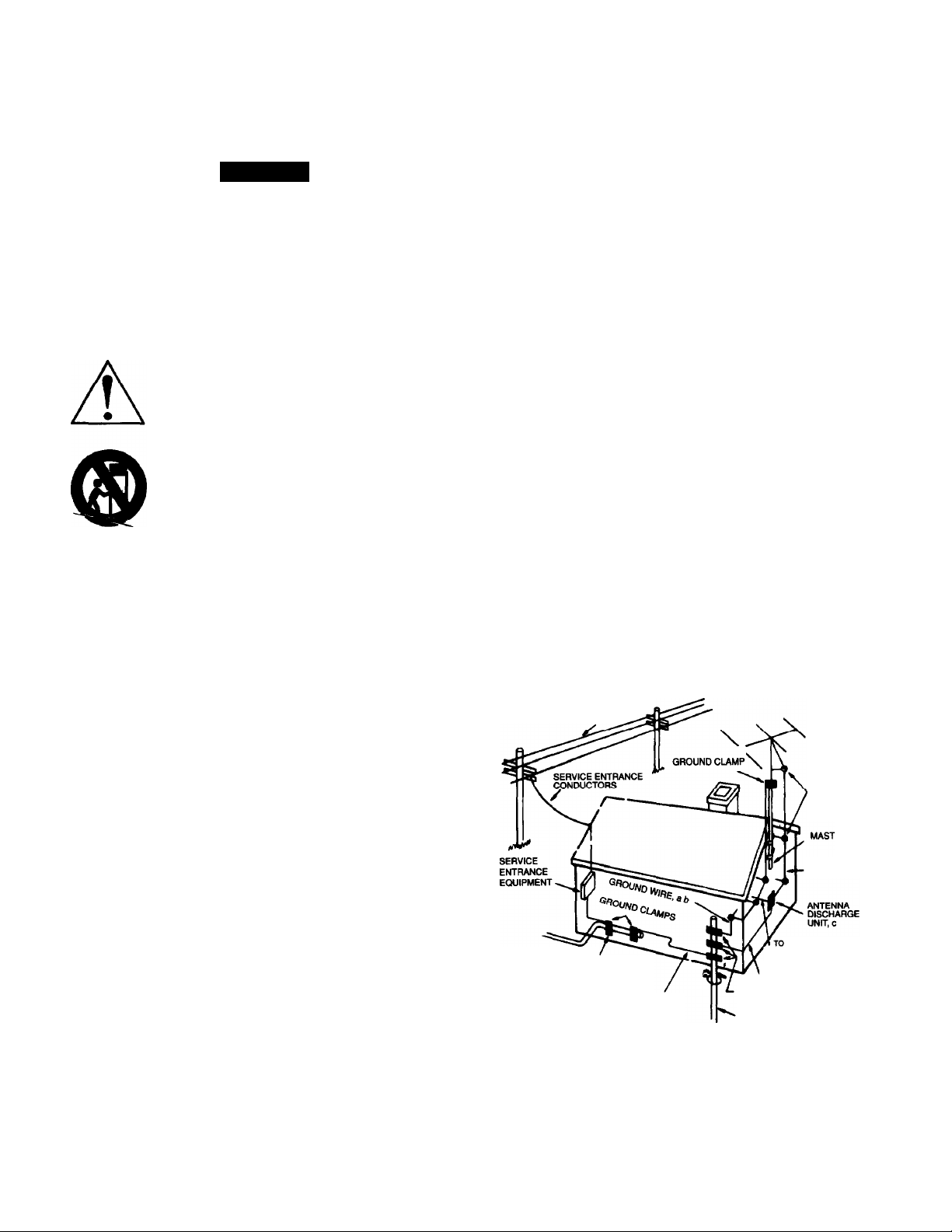
OUTDOOR ANTENNA GROUNDING
If an outside antenna is connected to your tuner or tuner-preamplifier, be
sure the antenna system is grounded so as to provide some protection
against voltage surges and built-up static charges. Section 810 of the
National Electrical Code, ANSI/NFPA No. 70-1984, provides information with
respect to proper grounding of the mast and supporting structure, grounding
of the lead-in wire to an antenna discharge unit, size of grounding
conductors, location of antenna discharge unit, connection to grounding
electrodes, and requirements for the grounding electrode.
a. Use No.lO AWQ (5.3 mm‘) copper, No.6 AWG (B.4 mm’) aluminum,
No.17 AWG (1.0 mm’) copper-clad steel or bronze wire, or larger, as a
ground wire.
b. Secure antenna lead-in and ground wires to house with stand-off
insulators spaced from 4-6 feet (1.22-1.83 m) apart.
c. Mount antenna discharge unit as close as possible to where lead-in
enters house.
d. Use jumper wire not smaller than No.6 AWG (13.3 mm’) copper, or the
equivalent, when a separate antenna-grounding electrode is used. See NEC
Section 810-21 G)-
EXAMPLE OF ANTENNA GROUNDINQ AS PER NATIONAL ELECTRICAL CODE INSTRUCTIONS
POWER SERVICE GROUNDING
ELECTRODE SYSTEM
(e g. Intenor metal water pipe)
CONTAINED IN ARTICLE 810 - RADIO AND TELEVISION EQUIPMENT
POWER lines
STANDOFF
INSULATORS, D
EXTERNAL ANTENNA
TERMINALS OF RADIO RECEIVER
GROUND WIRE, a.b
GROUND CLAMPS
BONDING JUMPER, d
OPTIONAL ANTENNA GROUNDING
ELECTRODE DRIVEN 8 FEET (2 44 M) INTO
THE EARTH IF REQUIRED BY LOCAL
COOES SEE NEC SECTION 810-21 (f)
ANTENNA
LEAD-IN WIRE
NOTE TO CATV SYSTEM INSTALLER
This reminder is provided to call the CATV system installer’s attention to
Article 820-22 of the National Electrical Code that provides guidelines for
proper grounding and, in particular, specifies that the cable ground shall be
connected to the grounding system of the building, as close to the point of
cable entry as practical.
Page 3

INTRODUCTION
Congratulations on your decision to purchase the GFA-5802 Stereo Power Amplifier. You have made a wise choice
that will reward you with exceptionally accurate and musical sound reproduction for years to come To realize the full potential
of your new amplifier, please read these operating and installation instructions thoroughly before attempting to connect it.
FEATURES
• Precision matched MOSFETs used throughout the signal path.
• Over 100,000 pF of power supply filter capacitance with low ESR for greater reserve capacity.
• Reduced number of gam stages improves signal reproduction accuracy.
• Custom toroidal power transformer with dual secondaries provides greater peak current capability.
• Separate front-end power supply complete with separate transformers.
• Dual High quality, gold plated binding posts.
• Independent thermal protection and distortion LED’s for each channel.
• Gold plated RCA jacks.
• Large external heatsinks for greater cooling capability of output devices.
• Heavy gauge, anodized aluminum front panel
• Powder coated, baked chassis and top cover for greater durability.
• Cooling vents on top cover for greater efficiency and cooler operation while driving low impedance loads
IMPORTANT NOTICE: ADCOM PROTECTION PLAN (USA ONLY)
understand the extent of the protection offered by the Warranty, its reasonable limitations, and what you should do in order to
obtain its benefits. Be sure to verify that the serial number printed on the rear panel matches the serial number on the outer
carton. If any number is altered or missing, you should notify us immediately in order to ensure that you have received a
genuine ADCOM product which has not been opened, mishandled, or tampered with in any way.
UNPACKING
electrical parameters as a routine part of ACCOM’s systematic quality control This, along with full operational and mechanical
testing, should ensure a product flawless in both appearance and performance After you have unpacked the GFA-5802,
inspect it for physical damage Save the shipping carton and all packing material as they are intended to reduce the possibility
of transportation damage, should the amplifier ever need to be shipped again. In the unlikely event damage has occurred,
notify your dealer immediately and request the name of the carrier so a written claim to cover shipping damages can be
initiated. THE RIGHT TO A CLAIM AGAINST A PUBLIC CARRIER CAN BE FORFEITED IF THE CARRIER IS NOT NOTIFIED
PROMPTLY IN WRITING AND IF THE SHIPPING CARTON AND PACKING MATERIALS ARE NOT AVAILABLE FOR
INSPECTION BY THE CARRIER. SAVE ALL PACKING MATERIALS UNTIL THE CLAIM HAS BEEN SETTLED.
ADCOM offers the enclosed valuable Limited Warranty. Please read the details on the Warranty Card carefully to
Before your new GFA-5802 left our factory, it was carefully inspected for physical imperfections and tested for all
PLACEMENT AND CARE OF THE GFA-5802
During normal home operation the heatsinks of the GFA-5802 will become very warm. However, there are instances
during high-level playback into low impedances when the heatsinks will become much warmer than usual. To ensure the
amplifier’s long-term, trouble-free operation, it is necessary to provide adequate ventilation for the heatsinks. Therefore, the
GFA-5802 should be kept away from external sources of heat such as radiators and hot-air ducts. The GFA-5802 should never
be placed with other heat-producing components in a cabinet or enclosure lacking free air flow
If you require that the GFA-5802 be mounted in an enclosed cabinet, it is recommended that the rear panel of the
cabinet be provided with ventilation openings at the top and bottom to allow air to circulate freely in the cabinet The top and
bottom panel of the amplifier’s chassis have been provided with vents to allow the necessary cooling of the internal
components. It is important that these vents are not obstructed in any way.
We recommend that you do not stack other components on top of the GFA-5802. This is particularly important If your
system includes low-impedance loudspeakers which are difficult to drive, or if you will consistently demand high volume levels
from the amplifier and speaker system. Not only will heat generated by the amplifier affect the performance of equipment
stacked on top of the GFA-5802, but the free flow of air through the ventilating slots in the amplifier may be partially obstructed
If you observe these recommendations, the GFA-5802 will perform reliably in any reasonable environment. You
should also pay attention to such normal considerations as protection from excessive dust and moisture. Occasional
vacuuming of accumulated dust on the chassis, heatsinks, panels and around the ventilating slots should be all that is
required
The optimal performance of your new GFA-5802 will ultimately depend on the care with which you make the
connections between the amplifier, preamplifier and the loudspeakers All input and output signal connections should be made
only with high quality, low-loss, low capacitance cables following the recommendations in the following relevant sections.
Page 4

WARNING
Whenever connections to or from the GFA-5802 are being made, be certain that the AC on/off switch of the ampiifier
is in the off position, the AC cord of the ampiifier is disconnected from the AC waii outiet and that aii associated
components are turned off.
RIGHT/LEFT UNBALANCED (RCA) iNPUTS O
The audio inputs to the GFA-5802 are through two high quality, gold plated RCA jacks to minimize high frequency line
losses, noise, etc. This input type is more common that the balanced XLR input (O) and is designed to work with an
unbalanced preamplifier. They will accept standard RCA type plugs, one for each channel, LEFT and RIGHT. The RIGHT input
IS generally represented by the color red, while LEFT is usually represented by either white or black.
To preserve the correct stereophonic effects, please be certain to connect the left output of the preamplifier or tunerpreamplifier to the RCA jack on the GFA-5802 labeled LEFT INPUT and the right output of the source component to the RIGHT
INPUT jack
To ensure that the performance designed into the GFA-5802 is realized, you should use the highest quality cables
feasible. Whatever cable you finally select, it should have low capacitance Generally speaking, a cable with a capacitance of
less than 100 pF will work best.
BALANCED/UNBLANCED SWITCHES O
These switches should “point” towards the input that you are using. If the unbalanced RCA inputs are being used, then
the switches should be in the unbalanced position. If you are using the balanced XLR inputs, then the switches should be in the
ba/anced position. It is nof suggested to connect both the balanced input to a balanced source and the unbalanced input to an
unbalanced source at the same time.
RIGHT/LEFT BALANCED (XLR) INPUTS O
When you are using a preamp that has balanced outputs (via XLR jacks), it may be directly connected to the GFA-
5802 using “balanced XLR" cables. Pushing the release tab on the top of the input will release the XLR
NORMAL SPEAKER OUTPUTS O
The GFA-5802 is “polarity correct” and does not invert phase. That is, any positive going signal at its input will appear
as a positive going signal at its output.
The GFA-5802’s connection to the loudspeakers are made through two high quality, five-way, gold plated binding
posts located on the rear panel. These terminals will accommodate either bare wire, tinned wire, terminal pins, spade lugs or
banana plugs, either single or dual. These output terminals are color coded RED and BLACK to indicate polarity. To ensure
correct stereo phasing, you must connect the RED output terminal (labeled ‘V’) to the loudspeaker input terminal color coded
RED (or labeled POSITIVE, ‘V’, POS, 8 OHMS or 4 OHMS). The BLACK binding post terminal on the amplifier (labeled ”-”)
2
Page 5

should be connected to the loudspeaker input terminal color coded BLACK (or labeled NEGATIVE, NEG, C, COMMON, G,
or GROUND).
The RIGHT OUTPUT should be connected to the right channel loudspeaker, as you face the pair of loudspeakers, and
the LEFT OUTPUT to the left channel loudspeaker.
Generally speaking, when making connections to the loudspeakers from the amplifier it is very important to use the
correct type and size of wire in order to avoid unnecessary loss of amplifier power in the cable, reduction of amplifier damping
factor and other undesirable conditions. It is suggested that with the GFA-5802 you shouid use at least 14AWG wire and
preferably 12AWG. Contact your local Adcom dealer for an appropriate selection of high end cables.
Virtually any stereo pair of loudspeakers can be connected to, and driven by the GFA-5802. The amplifier can drive
low impedances at more than adequate power levels with no difficulty. It should be noted here that many loudspeaker systems
which are nominally rated at 4 ohms drop in impedance, in some parts of their frequency range, sometimes to below 2 ohms.
You should not experience difficulties even with these very low impedance loads unless you demand excessively high volume
levels from the system.
The following diagrams show basic system wiring for two speaker options.
BASIC UNBALANCED WIRING DIAGRAM
Page 6

BI-WIRE SPEAKER OUTPUTS O
The GFA-5802 incorporates an additional set of output terminals to facilitate bi-wired speaker systems. In a bi-wired
system, there are two sets of speaker-wires that connect to each speaker (one for the low frequencies and one for the high
frequencies). To be able to bi-wire your speakers, the speakers need to be bi-wirable (having two sets of input terminals,
usually with a metal jumper installed between each pair). The following diagram conveys a basic bi-wired system.
AC LINE SOCKET O
The GFA-5802’sdetachable power cord is supplied with a “grounded" AC plug. Make certain that the power cable is
securely plugged into the AC Line Socket on the GFA-5802.
4
Page 7

FRONT PANEL FEATURES
POWER LED
This LED will glow whenever the AC ON/OFF switch is turned on and the GFA-5802 is energized. The POWER LED
indicates that there is AC voltage being fed to the amplifier, but it does not signify that all the amplifier’s circuits are in operation.
If, for example, the THERMAL PROTECTION LED glows, the amplifier will not produce sound even though the POWER LED
may still glow. Additionally, the internal power transformer is provided with a thermostat which will interrupt power to the
transformer if its temperature exceeds 125®C. This high temperature will seldom, if ever, be encountered unless the amplifier is
subjected to abnormal conditions, such as operation into loads of less than 2 ohms at very high listening levels for long periods
of time, etc Once the temperature within the transformer decreases to a normal level, the thermostat will reset itself
automatically and normal operation will resume
INSTANTANEOUS DISTORTION ALERT LED’s
The INSTANTANEOUS DISTORTION ALERT circuit is a unique ADCOM distortion detection system which reads all
forms of non-linear distortion such as THD, IM, slew-induced, “clipping”, etc. The INSTANTANEOUS DISTORTION ALERT
LED’s will light when distortion reaches 1% regardless of impedance, voltage/current phase angle or the reactance of the
loudspeakers which the amplifier is driving. Sometimes, when the amplifier is in use, the LED’s may occasionally flicker during
high volume listening, particularly if you are driving low impedances This flickering is no cause for concern The LED’s are
simply warning you that the amplifier has reached its maximum power output into the particular loudspeakers you are using. If,
however, the INSTANTANEOUS DISTORTION ALERT LED’s glow brightly or are illuminated most of the time during playback,
you are overdriving the amplifier and should turn down your volume control to reduce the listening level, otherwise it may cause
the THERMAL PROTECTION to be activated or, in extreme cases, damage your loudspeakers
THERMAL PROTECTION LED’s
The GFA-5802 is provided with a thermal protection circuit which will shut down the amplifier if either heatsink’s
temperature reaches 85®C The THERMAL PROTECTION LED’s will light whenever the thermal protection circuit on its
respective channel has been triggered and the amplifier is inoperative The thermal protection circuitry will typically be triggered
by very high power demands into impedances much lower than the amplifier is capable of driving at those levels. If either
amplifier channel's output through the loudspeaker(s) ceases abruptly, and one or both of the THERMAL PROTECTION LED’s
glow, you will know that the circuitry is protecting the amplification devices. Once the temperature of the heatsink(s) drops to a
safe operating level, the amplifier will automatically resume operation.
Activation of the thermal protection circuitry in the GFA-5802 is an indication that the amplifier has been overdriven or
that the load the loudspeakers are presenting to the amplifier is unreasonably low. If you wish to prevent recurring activation of
the thermal protection circuitry, you must reduce the volume level demands or correct the load-impedance condition which may
be causing activation of this circuitry, or both internal protection fuses may blow.
Another reason that the THERMAL PROTECTION LEDs will glow is if the Speaker Outputs (O or O) are shorted (if the
positive and negative wires were to touch together). If this occurs, you will experience severe distortion from the speakers for a
few seconds. The amplifier will then shut down and the PROTECTION LEDs will glow.
SERVICING
ADCOM has a Technical Service Department to answer questions pertinent to the installation and operation of your
unit. In the event of difficulty, please contact us for prompt advice. If your problem cannot be resolved through our combined
efforts, we may refer you to an authorized repair agency, or authorize return of the unit to our factory
Please address mail inquires to.
ADCOM Service Corporation
11 Eikins Road
East Brunswick, NJ 08816 USA
When calling or writing about your GFA-5802, be sure to note and reter to its serial number as well as the date of
purchase and the dealer from whom it was purchased. In the event the unit must be returned to our factory for service, you will
be instructed on the proper procedure when you call or write for a Return Authorization UNDER NO CIRCUMSTANCES
SHOULD YOUR UNIT BE SHIPPED TO OUR FACTORY WITHOUT PRIOR AUTHORIZATION.
If the original shipping carton and its fillers have been lost, discarded, or damaged, a duplicate carton may be obtained
from our Service Department for a nominal charge
Always ship PREPAID VIA UNITED PARCEL SERVICE (UPS) OR OTHER APPROVED CARRIER. DO NOT SHIP
VIA PARCEL POST, since the packing was not designed to withstand rough Parcel Post handling FREIGHT COLLECT
SHIPMENTS CAN NOT BE ACCEPTED UNDER ANY CIRCUMSTANCES.
Phone or fax inquires to'
Telephone: (908) 390-1130 or after 7/97 (732)
Fax: (908) 390-9152 or after 7/97 (732)
Monday through Friday
9:00 AM to 5:00 PM EST
Page 8

GFA-5802 SPECIFICATIONS
Power Rating (To FTC Requirements)
300 watts continuous average power into 8 ohms: 20Hz and 20kHz with both channeis driven at iess than 0.18% THD
450 watts continuous average power into 4 ohms: 20Hz and 20kHz with both channels driven at less than 0.18% THD
IM Distortion (SMPTE)
1 watt to 300 watts into 8 ohms....................................................................................................................... < 0.075%
1 watt to 450 watts into 4 ohms....................................................................................................................... < 0.075%
IM Distortion (CCIF, Any Combination from 4kHz to 20kHz)
300 watts into 8 ohms........................................................................................................................................ < 0 075%
450 watts into 4 ohms........................................................................................................................................ <0 075%
THD + Noise at 300 watts into 8 ohms (Typicai)
20Hz..................................................................................................................................................................... 0.015%
1kHz....................................................................................................................................................................... 0.02%
10kHz .................................................................................................................................................................... 0.09%
20kHz..................................................................................................................................................................... 0.15%
THD + Noise at 450 watts into 4 ohms (Typical)
20Hz..................................................................................................................................................................... 0.025%
1kHz..................................................................................................................................................................... 0.025%
10kHz..................................................................................................................................................................... 0.09%
20kHz...................................................................................................................................................................... 0.15%
Frequency Response @ 1 Watt into 8 ohms (10Hz to 20kHz).................................................................................+0, -0.25dB
Power Bandwidth (-3dB)........................................................................................................................................3Hz to 130kHz
Dynamic Headroom into 4 ohms.........................................................................................................................................2.3dB
Signal to Noise Ratio, “A” Weighted (300 watts onto 8 ohms)......................................................................................> 105dB
Gain........................................................................................................................................................................................29 dB
Input Impedance
Unbalanced.....................................................................................................................................................105K ohms
Balanced (bridged)........................................................................................................................................... 10K ohms
Input Sensitivity
for 1 Watt output.............................................................................................................................................................0.1 voits
for 300 Watts output...................................................................................................................................................... 1.7 voits
Rise Time (5kHz, 90 V peak-to-peak square wave, 20% to 80%)...................................................................................2.25 pS
Power Consumption (Continuous, Both Channels Driven)
Quiescent............................................................................................................................................................... 540VA
Maximum............................................................................................................................................................... 1440VA
300 watts into 8 ohms............................................................................................................................................ 1340VA
Power (Available in 230VAC by special order)............................................................................................... 15VAC - 50/60Hz
Chassis Dimensions...........................................................................................................13Ve” (mm) x 17” (432mm) x 8" (mm)
Maximum Dimensions..................................................................................................... ^SУг" (mm) x 17” (432mm) x814 ” (mm)
Weight............................................................................................................................................................................. 48 lb. (kg)
Weight, Packed............................................................................................................................................................... 55 lb. (kg)
ADCOM®
11 Elkins Road
East Brunswick, NJ 08816 U.S.A.
Tel: (972) or (908) 390-1130 ♦ Fax: (972) or (908) 390-9152
 Loading...