

Page 1

>4DC0M
details you can hear
GFA-5500
High Current
Power Amplifier
OWNER’S MANUAL
Page 2
THE FOLLOWING PRECAUTIONS AND SAFETY INSTRUCTIONS
ARE REQUIREMENTS OF UL AND CSA SAFETY REGULATIONS
Warning: To reduce the risk of fire or electric shock, do not expose
this unit to rain or moisture.
CAUTION
A
RISK OF ELECTRIC SHOCK
DO NOT OPEN
1l
AVIS: RISQUE DE CHOC ELECTRIQUE-NE PAS OUVRIR,
The graphic symbol of a lightning flash with an arrow
point within a triangle signifies that there is dangerous
voltage within the unit and it poses a hazard to anyone
removing the cover to gain access to the interior of the
unit.Only qualified service personnel should make
any such attempt.
The graphic symbol of an exclamation point within an
equilateral triangle warns a user of the device that it is
necessary to refer to the instruction manual and its
warnings for proper operafion of the unit.
Do not place this unit on an unstable cart, stand, tripod,
bracket, or table. The unit may fall, causing serious
injury to a child or adult, and serious damage to the
unit. Use only with a cart, stand, tripod, bracket, or table
recommended by the manufacturer, or sold with the
unit. Any mounting of the device should follow the man
ufacturer's instructions, and should use a mounting ac
cessory recommended by the manufacturer.
Read all the safety and operating instructions before connecting or using
this unit.
Retain this notice and the owner's manual for future reference.
All warnings on the unit and in its operating instructions should be adhered to.
All operating and use instructions should be followed.
Do not use this unit near water: for example, near a bathtub, washbowl,
kitchen sink, laundry tub, in a wet basement, or near a swimming pool.
The unit should be installed so that its location or position does not interfere
with its proper ventilation. For example, it should not be situated on a bed,
sofa, rug, or similar surface that may block the ventilation openings: or
placed in a built-in installation, such as bookcase or cabinet, that may
impede the flow of air through its ventilation openings.
The unit should be situated away from heat sources such as radiators, heat
registers, stoves, or other devices (including amplifiers) that produce heat.
The unit should be connected to a power-supply outlet only of the voltage
and frequency marked on its rear panel.
The power-supply cord should be routed so that it is not likely to be walked
on or pinched, especially near the plug, convenience receptacles, or where
the cord exits from the unit.
ATTENTION
POUR PRÉVENIR LES CHOCS ÉLECTRIQUES NE PAS UTILISER
CETTE FICHE POLARISÉE AVEC UN PROLONGATEUR, UNE PRISE
DE COURANT OU UNE AUTRE SORTIE DE COURANT, SAUF SI LES
LAMES PEUVENT ÊTRE INSÉRÉES À FOND SANS EN LAISSER AU
CUNE PARTIE À DÉCOUVERT.
CAUTION
TO PREVENT ELECTRIC SHOCK DO NOT USE THIS POLARIZED PLUG
WITH AN EXTENSION CORD, RECEPTACLE OR OTHER OUTLET UN
LESS THE BLADES CAN BE FULLY INSERTED TO PREVENT BLADE
EXPOSURE.
CAUTION
Any outdoor antenna must be located away from all power lines,
POWER LINES
OUTDOOR ANTENNA GROUNDING
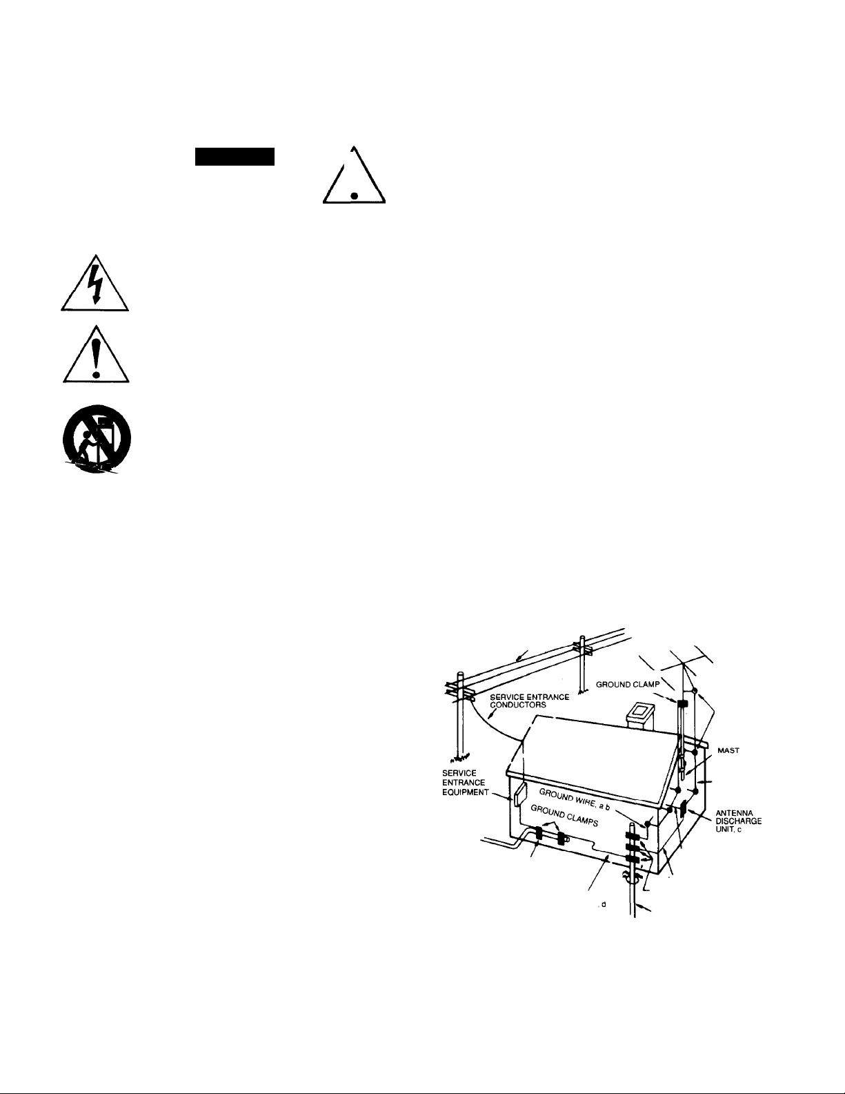
If an outside antenna Is connected to your tuner or tuner-preamplifier, be
sure the antenna system is grounded so as to provide some protection
against voltage surges and built-up static charges. Section 810 of the
National Electrical Code, ANSI/NFPA No. 70-1984, provides information with
respect to proper grounding of the mast and supporting structure, grounding
of the lead-in wire to an antenna discharge unit, size of grounding
conductors, location of antenna discharge unit, connection to grounding
electrodes, and requirements for the grounding electrode.
a. Use No.10 AWG (5.3 mm^) copper, No.8 AWG (8.4 mm^) aluminum.
No.17 AWG (1.0 mm") copper-clad steel or bronze wire, or larger, as a
ground wire.
b. Secure antenna lead-in and ground wires to house with stand-off
insulators spaced from 4-6 feet (1.22-1.83 m) apart.
c. Mount antenna discharge unit as close as possible to where lead-in
enters house.
d. Use jumper wire not smaller than No.6 AWG (13.3 mm") copper, or the
equivalent, when a separate antenna-grounding electrode is used. See NEC
Section 810-21 (j).
EXAMPLE OF ANTENNA GROUNDING AS PER NATIONAL ELECTRICAL CODE INSTRUCTIONS
CONTAINED IN ARTICLE 810 ■ RADIO AND TELEVISION EQUIPMENT
POWER LINES
STANDOFF
INSULATORS, b
ANTENNA
LEAD-IN WIRE
Clean unit only as recommended in its instruction manual.
The power-supply cord of the unit should be unplugged from the wall outlet
when it is to be unused for a long period of time.
Care should be taken so that objects do not fall, and liquids are not spilled,
into the enclosure through any openings.
This unit should be serviced by qualified service personnel when:
A. The power cord or the plug has been damaged: or
B. Objects have fallen, or liquid has been spilled, into the unit: or
C. The unit has been exposed to rain, or liquids of any kind: or
D. The unit does not appear to operate normally, or exhibits a
marked change in performance: or
E. The device has been dropped, or the enclosure damaged.
DO NOT ATTEMPT SERVICING OF THIS UNIT YOURSELF.
REFER SERVICING TO QUALIFIED SERVICE PERSONNEL.
TO EXTERNAL ANTENNA
POWER SERVICE GROUNDING
ELECTRODE SYSTEM
(e. g. interior metal water pipe)
BONDING JUMPER
OPTIONAL ANTENNA GROUNDING
ELECTRODE DRIVEN 8 FEET (2.44 M) INTO
THE EARTH IF REQUIRED BY LOCAL
CODES. SEE NEC SECTION 810-21 (I)
TERMINALS OF RADIO RECEIVER
GROUND WIRE, a,b
GROUND CLAMPS
NOTE TO CATV SYSTEM INSTALLER
This reminder is provided to call the CATV system installer's attention to
Article 820-22 of the National Electrical Code that provides guidelines for
proper grounding and, in particular, specifies that the cable ground shall be
connected to the grounding system of the building, as close to the point of
cable entry as practical.
Page 3

INTRODUCTION
Congratulations on your decision to purchase the GFA-5500 Stereo Power Amplifier. You have made a wise choice that
will reward you with exceptionally accurate and musical sound reproduction for years to come. To realize the full
potential of your new amplifier, please read these operating and installation instructions thoroughly before attempting to
connect it. Furthermore, it is a good idea to keep this manual handy for future reference.
FEATURES
Precision matched MOSFETs used throughout the signal path.
80,000 pF of power supply filter capacitance with low ESR for greater reserve capacity.
Low number of gain stages improves signal reproduction accuracy.
Custom toroidal power transformer provides better regulation and greater peak current capability.
High quality, gold plated binding posts.
Independent thermal overload and distortion LEDs for each channel.
Gold plated, brass RCA jacks with Teflon insulators.
Large, exposed heatsinks for greater cooling capability of output devices.
Heavy gauge, anodized aluminum front panel.
Powder coated, baked chassis and top cover for greater durability.
Increased cooling vents on top cover for greater efficiency and cooler operation while driving low impedance loads.
IMPORTANT NOTICE
ADCOM PROTECTION PLAN
(USA ONLY)
ADCOM offers the enclosed valuable Limited Warranty. Please read the details on the Warranty Card carefully to
understand the extent of the protection offered by the Warranty, its reasonable limitations, and what you should do in
order to obtain its benefits.
Be sure to verify that the serial number printed on the rear panel matches the serial number on the outer carton. If
any number is altered or missing, or if the ADCOM Warranty Card is not included in the carton, you should notify us
immediately in order to ensure that you have received a genuine ADCOM product which has not been opened,
mishandled, or tampered with in any way.
Page 4

UNPACKING
Before your new GFA-5500 left our factory, it was carefully inspected for physical imperfections and tested for all
electrical parameters as a routine part of ADCOM's systematic quality control. This, along with full operational and
mechanical testing, should ensure a product flawless in both appearance and performance. After you have unpacked the
GFA-5500, inspect it for physical damage. Save the shipping carton and all packing material as they are intended to
reduce the possibility of transportation damage, should the amplifier ever need to be shipped again. In the unlikely event
damage has occurred, notify your dealer immediately and request the name of the carrier so a written claim to cover
shipping damages can be initiated
THE RIGHT TO A CLAIM AGAINST A PUBLIC CARRIER CAN BE FORFEITED IF THE CARRIER IS NOT NOTIFIED
PROMPTLY IN WRITING AND IF THE SHIPPING CARTON AND PACKING MATERIALS ARE NOT AVAILABLE FOR
INSPECTION BY THE CARRIER. SAVE ALL PACKING MATERIALS UNTIL THE CLAIM HAS BEEN SETTLED.
INSTALLING THE GFA-5500
During normal home operation the external heatsinks of the GFA-5500 will become warm. However, there are instances
during high-level playback into low impedances when the heatsinks will become much warmer than usual. To ensure the
amplifier's long-term, trouble-free operation it is necessary to provide adequate ventilation for the heatsinks. Therefore,
the GFA-5500 should be kept away from external sources of heat such as radiators and hot-air ducts. The GFA-5500
should never be placed with other heat-producing components in a cabinet or enclosure lacking free air flow.
If you require that the GFA-5500 be mounted in an enclosed cabinet, it is recommended that the rear panel of the cabinet
be provided with ventilation openings at the top and bottom to allow air to circulate freely in the cabinet. The top and
bottom panel of the amplifier’s chassis have been provided with vents to allow the necessary cooling of the internal
components. It is imperative that these vents are not obstructed in any way.
We recommend that you do not stack other components on top of the GFA-5500. This is particularly important If your
system includes low-impedance loudspeakers which are difficult to drive, or if you will consistently demand high volume
levels from the amplifier and speaker system. Not only will heat generated by the amplifier affect the performance of
equipment stacked on top of the GFA-5500, but the free flow of air through the ventilating slots in the amplifier may be
partially obstructed.
If you observe these recommendations, the GFA-5500 will perform reliably in any reasonable environment. You should
also pay attention to such normal considerations as protection from excessive dust and moisture. Occasional vacuuming
of accumulated dust on the chassis, heatsinks, panels and around the ventilating slots should be all that is required.
The optimal performance of your new GFA-5500 will ultimately depend on the care with which you make the connections
between the amplifier, preamplifier and the loudspeakers. All input and output signal connections should be made only
with high quality, low-loss, low capacitance cables following the recommendations in the following relevant sections.
Please refer to the rear panel diagram to identify all the connector locations.
WARNING
DO NOT EXPOSE THE AMPLIFIER TO RAIN, WATER, OR MOISTURE OF ANY KIND.
RIGHT/LEFT INPUT CD
The audio inputs to the GFA-5500 are through two high quality, gold plated RCA jacks to minimize high frequency losses,
noise, etc. They will accept standard RCA type plugs, one for each channel, LEFT and RIGHT, usually supplied at the
ends of interconnecting cables. To ensure that the performance designed into the GFA-5500 is realized, you should use
the highest quality cables feasible. There are many cables which are designed specifically for these applications and
your ADCOM dealer can be of help in selecting the best cable for your application. Whatever cable you finally select, it
should have low capacitance. This is particularly important if you use a long run between the preamplifier and amplifier.
Generally speaking, a cable with a capacitance of less than 100 pF will work best
The load impedance which the GFA-5500 inputs present to the source preamplifier or tuner-preamplifier is 49.9k ohms.
This load impedance results in minimal amplifier noise when used with a source component of low output impedance
such as an ADCOM preamplifier or tuner/preamplifier.
To preserve the correct stereophonic effects, please be certain to connect the left output of the preamplifier or tunerpreamplifier to the RCA jack on the GFA-5500 labeled LEFT INPUT and the right output of the source component to the
RIGHT INPUT jack.
Page 5

AIXOM
10 Timber Lane
Marlboro. N.J. 0774€
Uodti CrA-5500
Poter fiSVAC 50/60H2
Po^ef co^svfTtpiion{maM): i440W
Uode in USA
Ato v9#r port$ intid*. Pr^f
t^rvicinq to qoo/lftad p0r3onn^.
AC powtr /u*t f?A ABC/250V
(fn)
WAPN/NC: To reduce trtf /•I's* or fke
Of e/dctrkr V»oc*. (*o nef eroosa Ihn
appMonc* to roin Of moisture.
An£NVOAi: Pouf e\4t»f tout rha^
6e ieu ou c^oc t/eoiritju*. r*« (>os
etposer cet opporeit a ¡o p/uic oo a
/ 'humid"te'
AVIS: Pisaoe Oe cnoc e'i&ctriquo-ne
pas ouurif.
Stria/ /
ABA
GFA-5500 Rear Panel Diagram
WARNING
WHENEVER CONNECTIONS TO OR FROM THE GFA-5500 ARE BEING MADE, BE CERTAIN THAT THE
AC ON/OFF SWITCH OF THE AMPLIFIER IS IN THE OFF POSITION, THE AC CORD OF THE AMPLIFIER
IS DISCONNECTED FROM THE AC WALL OUTLET AND THAT ALL ASSOCIATED COMPONENTS ARE
OFF.
RIGHT/LEFT OUTPUT ©
The GFA-5500's connection to the loudspeakers are made through two high quality, five-way, gold plated binding posts
located on the rear panel. These terminals will accommodate either bare wire, tinned wire, terminal pins, spade lugs or
banana plugs, both single and dual. These output terminals are color coded RED and BLACK to indicate polarity. To
ensure correct stereo phasing, you must connect the RED output terminal (labeled “+") to the loudspeaker input terminal
color coded RED (or labeled POSITIVE, "+”, POS, 8 OHMS or 4 OHMS). The BLACK binding post terminal on the
amplifier (labeled "-”) should be connected to the loudspeaker input terminal color coded BLACK (or labeled NEGATIVE,
NEG, C, COMMON, G, or GROUND).
The RIGHT OUTPUT should be connected to the right channel loudspeaker, as you face the pair of loudspeakers, and
the LEFT OUTPUT to the left channel loudspeaker.
In order to ensure that connections to the loudspeakers are correct, you must be able to identify each wire conductor of
the loudspeaker cables at both ends of the cables. This is relatively easy to do since most loudspeaker cables'consist of
two parallel, stranded conductors in a flexible insulation, with a coding system for wire identification. Sometimes there is
a colored “tracer" wrapped around one of the conductors; some cables have one of the conductors colored silver and the
other copper; some have a “ridge" molded on the insulation of one of the conductors, while others are imprinted with
and/ormarkings. Your ADCOM dealer also sells special loudspeaker cables and these are most often labeled with
respect to polarity.
Page 6

NOTE
THE GFA-5500 IS POLARITY CORRECT AND DOES NOT INVERT PHASE. THAT IS, ANY POSITIVE GOING
SIGNAL AT ITS INPUT WILL APPEAR AS A POSITIVE GOING SIGNAL AT ITS OUTPUT,
Generally speaking, when making connections to the loudspeakers from the amplifier it is very important to use the
correct type and size of wire in order to avoid unnecessary loss of amplifier power in the cable, reduction of amplifier
damping factor and other undesirable conditions. For runs up to twelve feet, ordinary “zip" or lamp cord, made up of
AWG18 stranded wire and available in a variety of insulation colors may be used. For runs up to forty feet, AWG16
stranded wire should be used as a minimum to prevent power losses. For lengths over forty feet and not exceeding sixty
feet, use at least AWG14 stranded wire. Runs exceeding sixty feet require the use of heavier conductors such as
AWG12.
Regardless of the cables you select to connect your loudspeakers, there are some additional requirements which you
should observe in order to ensure maximum performance from your amplifier. It is most important that you make certain
the wiring you have selected has as low a capacitance as possible. All amplifiers, particularly wide bandwidth audio
amplifiers are susceptible to the capacitance cables present to their outputs at extremely high frequencies. This
capacitance, in conjunction with the inductance of the wire itself and the reactive load of the loudspeakers, can create
anomalies at ultrasonic frequencies which, although inaudible, can affect performance in the audible range.
There are several different ways to connect the wiring to the RIGHT and LEFT OUTPUTS, The methods used will
depend on the specific type of connectors supplied with the loudspeakers, the speaker cables, etc. As a matter of
course, we prefer to use banana plugs because it is generally the most secure method of connection. Also, the springs
of the banana plugs create a selTcleaning action which ensures the best contact between the binding posts and the
connectors themselves. There are “sockets" provided in the center of the binding posts’ studs which permit secure
seating of the banana plugs. Before inserting the banana plug into the binding post, ensure the binding post is securely
hand tightened in a clockwise direction.
Additionally, when connecting the cables to the amplifier and loudspeakers, it is important that you “tin” the wires with
good quality electronic solder in order to minimize contact resistance. Tinning prevents the buildup of surface
compounds which can form on copper wire and increase its contact resistance. It is partly for this reason that banana
plugs are preferred. However, make sure that the cable ends are tinned before you make the cable connections to the
banana plugs. Alternatively, you can use “crimped’’ pins or other lugs to ensure low contact resistance at the connection
to the amplifier and loudspeakers.
If you prefer to use other methods of connection, unscrew the insulated head of the binding post until the hole in the
binding post stud is accessible. You can then insert the bare or tinned wire, or terminal pin, through the hole. You can
also use the many variety of spade lugs available by simply placing the tines of the spade lug onto the binding post stud.
Turn the insulated head of the binding post clockwise until the wire or connector is firmly secured. Finger pressure is
sufficient and you should not use pliers or other tools which could damage or over tighten the binding post assembly.
The binding post has been designed in such a way that finger pressure is all that is required to cause a “pinching” action
among the different metal surfaces to ensure proper connection.
All loudspeakers having a nominal impedance down to 4 ohms can be connected to, and driven by the GFA-5500. The
amplifier can drive these low impedances at more than adequate power levels with no difficulty. It should be noted here
that many loudspeaker systems which are nominally rated at 4 ohms drop in impedance, in some parts of their frequency
range, to as low as 2 ohms (and some others to even less than 2 ohms). You will not experience difficulties even with
these very low impedance loads unless you demand excessively high volume levels from the system.
In most applications, you can drive two or more sets of loudspeakers. You should note, however, that when
loudspeakers are paralleled, the impedance presented to the amplifier is lower than the nominal impedance of each
loudspeaker. In other words, if you parallel two 8 ohm sets of loudspeakers, the resultant impedance presented to the
amplifier will be 4 ohms. If 8 ohm and 4 ohm loudspeakers are paralleled, the resultant impedance will be approximately
2.6 ohms. In this last situation, depending upon the lowest impedance of the nominally 4 ohm speakers, and if excessive
power demands are placed on the amplifier, you may trigger the THERMAL PROTECTION on the amplifier or blow one of
the EXTERNAL PROTECTION FUSES. See its respective section for more information. For convenient switching of
multiple sets of speakers with impedance protection for the amplifier, you should consider the use of an ADCOM speaker
selector. These are available from your local ADCOM dealer.
Page 7

AC LINE CORD ®
The AC cord provides power to operate all the GFA-5500's circuits. Its plug can be connected to a standard wall outlet
provided the outlet supplies a voltage compatible with the "Power" requirements printed on the rear of the GFA-5500.
NOTE
The GFA-5500’s power cord is supplied with a "polarized" AC plug as required by UL/CSA standards and the
National Electrical Code. To minimize the risk of electrical shock and to ensure minimal hum from the system,
do not defeat the polarity ensuring feature of the plug (one wide blade and one narrow blade). To prevent
electrical shock, do not use this polarized plug with an extension cord or other outlet unless the blades can be
fully inserted to prevent blade exposure
AC POWER FUSE ®
The AC POWER FUSE protects the electronic circuits of the GFA-5500. This fuse will normally blow only if there is an
overload within the GFA-5500. For continued protection of the electronic circuits it is strongly recommended that it be
replaced only with a fuse of the same type and value as printed on the rear panel of the amplifier.
Whenever the AC ON/OFF SWITCH on the front panel is turned on and the amplifier is energized, the POWER LED will
glow. If turning on the amplifier does not cause the POWER LED to glow, this may indicate that the AC POWER FUSE is
blown. Unplug the AC LINE CORD from the AC wall outlet and turn the AC ON/OFF SWITCH off and check the fuse. If
the fuse is blown, replace it only with one of the same type and value as printed on the rear panel of the amplifier. If,
after replacing the fuse, it blows immediately upon turning on the amplifier (POWER LED does not glow), a failed
electronic component or other internal problem must be suspected. Make no further attempts at fuse replacement or
operation of the amplifier. Refer the problem to competent ADCOM authorized service personnel.
WARNING
BEFORE ATTEMPTING TO CHECK OR REPLACE A BLOWN FUSE, BE CERTAIN TO UNPLUG THE AC LINE
CORD FROM THE AC WALL OUTLET TO PREVENT POSSIBLE ELECTRICAL SHOCK.
To remove a blown or suspect fuse from its holder, use only a 1/4" standard screwdriver to prevent damage to the fuse
holder. Simply press lightly on the fuse holder cap and turn counterclockwise. The cap will pop out after a quarter turn.
Once a new fuse has been installed in the fuse holder cap, insert it into the fuse holder body and press lightly while
turning the cap clockwise until it is firmly seated. Be certain not to cause cross threading of the fuse holder body and cap
to prevent damage to the fuse holder. DO NOT FORCE THE FUSE HOLDER CAP INTO THE THREADS. Seating of the
cap in the fuse holder body should be easily accomplished without excessive force.
WARNING
The fuses listed here and their time/current blowing points have been carefully selected and thoroughly tested to
deliver optimal performance while still accomplishing their protective functions. Replace the AC POWER FUSE only
with one identical in type and rating as printed on the rear panel. DO NOT USE ANY SUBSTITUTE FUSES WITH
DIFFERENT RATINGS OR VALUES. Failure to observe this precaution may cause serious damage to the amplifier
circuits, MAY CREATE A FIRE HAZARD, AND MAY VOID THE WARRANTY.
AC POWER FUSE For 115 Volt operation: 12 AMP ABC/250V
AC POWER FUSE For 230 Volt operation: 6 AMP ABC/250V
AC ON/OFF SWITCH ©
The AC ON/OFF SWITCH controls power to the power transformer circuits of the GFA-5500. Whenever the GFA-5500 is
energized the POWER LED will glow. Depress the push button switch to energize the GFA-5500. Release the switch to
turn the amplifier off.
Page 8

POWER LED (D
This LED will glow whenever the AC ON/OFF switch is turned on and the GFA-5500 is energized. If the AC LINE FUSE
blows the POWER LED will cease to glow.
The POWER LED indicates that there is AC voltage being fed to the amplifier, but it does not signify that all the
amplifier's circuits are in operation. If, for example, you have blown one or more of the EXTERNAL PROTECTION
FUSES, the amplifier will not operate. That is, the amplifier will not produce any audio signal even though the POWER
LED is glowing. Similarly, if the THERMAL PROTECTION LED glows, the amplifier will not produce sound even though
the POWER LED may still glow.
Additionally, the internal power transformer is provided with a thermostat which will interrupt power into the transformer if
its temperature exceeds 125°C. This high temperature will seldom, if ever, be encountered unless the amplifier is
subjected to abnormal conditions, such as operation into loads of less than 3 ohms at very high listening levels, etc. If
the AC POWER FUSE is not blown, the POWER LED is out, the THERMAL PROTECTION LED is out and the
EXTERNAL PROTECTION FUSES are intact, this would indicate that the thermostat within the transformer has opened.
Once the temperature within the transformer decreases to a normal level, the thermostat will reset itself automatically and
normal operation will resume. If you are to avoid continually tripping the thermostat in the transformer, you must reduce
the sound level demands, correct the load impedance of the loudspeakers, or both.
INSTANTANEOUS DISTORTION ALERT LEDs CU
The INSTANTANEOUS DISTORTION ALERT circuit is a unique ADCOM distortion detection system which reads all
forms of non-linear distortion such as THD, IM, slew-induced, “clipping”, etc. The INSTANTANEOUS DISTORTION
ALERT LEDs will light when distortion reaches 1% regardless of impedance, voltage/current phase angle or the
reactance of the loudspeakers which the amplifier is driving. Sometimes, when the amplifier is in use, the LEDs may
occasionally flicker during high volume listening, particularly if you are driving low impedances. This flickering is no
cause for concern. The LEDs are simply warning you that the amplifier is approaching its maximum power output into the
particular loudspeakers you are using. If, however, the INSTANTANEOUS DISTORTION ALERT LEDs glow brightly or
are illuminated most of the time during playback, you are overdriving the amplifier and should turn down your volume
control to reduce the listening level or you may blow one or more of the EXTERNAL PROTECTION FUSES, cause the
THERMAL PROTECTION to be activated or, in extreme cases, damage your loudspeakers.
GFA-5500 Front Panel Diagram
Page 9

THERMAL PROTECTION LEDs ®
The GFA-5500 is provided with a thermal protection circuit which will shut down the amplifier if either heatsink’s
temperature reaches 85°C. The THERMAL PROTECTION LEDs will light whenever the thermal protection circuit on its
respective channel has been triggered and the amplifier is inoperative. The thermal protection circuitry will typically be
triggered by very high power demands into impedances much lower than the amplifier is capable of driving at those
levels. If either amplifier channel’s output through the loudspeaker(s) ceases abruptly, and one or both the THERMAL
PROTECTION LEDs glow, you will know that its heatsink temperature has become unacceptably high and the circuitry is
protecting the amplification devices. Please note that the POWER LED will remain on and the amplifier will still be
energized. Once the temperature of the heatsink(s) drops to a safe operating level, the amplifier will automatically
resume operation.
NOTE
ACTIVATION OF THE THERMAL PROTECTION CIRCUITRY IN THE GFA-5500 IS AN INDICATION THAT THE
AMPLIFIER HAS BEEN OVERDRIVEN OR THAT THE LOAD THE LOUDSPEAKERS ARE PRESENTING TO THE
AMPLIFIER IS UNREASONABLY LOW. IF YOU WISH TO PREVENT RECURRING ACTIVATION OF THE
THERMAL PROTECTION CIRCUITRY, YOU MUST REDUCE THE VOLUME LEVEL DEMANDS OR CORRECT
THE LOAD-IMPEDANCE CONDITION WHICH MAY BE CAUSING ACTIVATION OF THIS CIRCUITRY, OR BOTH
EXTERNAL PROTECTION FUSES ©
There is an additional protection provided to the GFA-5500 in the form of EXTERNAL PROTECTION FUSES for the DC
rails on each channel. These fuses will blow if excessive current demands are made of the amplifier, either long term or
short term, and are meant to protect not only the loudspeakers, but the power output devices as well.
If the amplifier ceases to operate from either one or both channels, particularly during high level passages or long term
high volume playback, and the POWER LED glows while the THERMAL PROTECTION LEDs are out, chances, are that
one or more of the EXTERNAL PROTECTION FUSES are blown.
Your GFA-5500 is designed to activate its protection devices reliably, particularly when the amplifier is carelessly
operated beyond its limitations Other types of protection circuits, beyond the methods used in your amplifier usually
result in deterioration of the audio quality of the unit.
Should the EXTERNAL PROTECTION FUSES on the DC rails need to be replaced, only a fuse of identical value and
type as printed on the rear panel must be used.
WARNING
The fuses listed here and their time/current blowing points have been carefully selected and thoroughly tested to
deliver optimal performance while still accomplishing their protective functions. Replace the EXTERNAL
PROTECTION FUSES only with one identical in type and rating as printed on the rear panel. DO NOT USE ANY
SUBSTITUTE FUSES WITH DIFFERENT RATINGS OR VALUES Failure to observe this precaution may cause
serious damage to the amplifier circuits, MAY CREATE A FIRE HAZARD, AND MAY VOID THE WARRANTY.
EXTERNAL PROTECTION FUSE VALUE/TYPE; 8 AMP AGC/250 VOLT
WARNING
THERE ARE POTENTIALLY LETHAL VOLTAGES WITHIN THE GFA-5500 AMPLIFIER. REMOVING THE TOP
COVER GREATLY INCREASES YOUR CHANCE OF INADVERTENTLY EXPOSING YOURSELF TO EXTREME
DANGER. REFER ALL SERVICING TO QUALIFIED, ADCOM AUTHORIZED SERVICE PERSONNEL DO NOT
ATTEMPT TO SERVICE, REPLACE, OR REPAIR ANY INTERNAL COMPONENT YOURSELF.
Page 10

CARING FOR YOUR GFA-5500
Great care has been taken by ADCOM to ensure that your amplifier is as flawless in appearance as it is electronically. The
front panel Is a heavy gauge, high-grade aluminum extrusion carefully finished and anodized for durability. The chassis, top
cover and rear panels are heavy gauge steel, that has been powder coated and baked to ensure a lasting finish. If the front
panel, top or sides become dusty or finger printed, they can be cleaned with a soft lint free cloth, slightly dampened with a very
mild detergent solution or glass cleaner.
WARNING!
Do not spray or pour liquids of any kind on the GFA-5500
SERVICING
ADCOM has a Technical Service Department to answer questions pertinent to the installation and operation of your unit. In
the event of difficulty, please contact us for prompt advice. If your problem cannot be resolved through our combined efforts,
we may refer you to an authorized repair agency, or authorize return of the unit to our factory. To aid us in directing you to a
convenient service center, it would be helpful if you indicate which major city is accessible to your home.
Please address mail inquires to:
ADCOM Service Corporation
10 Timber Lane
Marlboro, NJ 07746 USA
For Fax inquires, please include a return Fax number for the reply. When calling or writing about your GFA-5500, be sure to
note and refer to its serial number as well as the date of purchase and the dealer from whom it was purchased. It is helpful in
any communications to us, please include a daytime phone number where we may reach you. In the event the unit must be
returned to our factory for service, you will be instructed on the proper procedure when you call or write for a Return
Authorization. UNDER NO CIRCUMSTANCES SHOULD YOUR UNIT BE SHIPPED TO OUR FACTORY WITHOUT PRIOR
AUTHORIZATION, OR PACKED IN OTHER THAN ITS ORIGINAL CARTON AND FILLERS.
If the original shipping carton and its fillers have been lost, discarded, or damaged, a duplicate carton may be
obtained from our Service Department for a nominal charge.
Always ship PREPAID VIA UNITED PARCEL SERVICE (UPS) OR OTHER APPROVED CARRIER. DO NOT SHIP
VIA PARCEL POST, since the packing was not designed to withstand rough Parcel Post handling.
Phone, Fax or E-mail inquires to:
Tel.: 732-683-2356
Fax: 732-683-9790
Monday through Friday
9:00 AM to 5:00 PM EST
E-Mail: service@adcom.com
FREIGHT COLLECT SHIPMENTS WILL NOT BE ACCEPTED
UNDER ANY CIRCUMSTANCES.
8
Page 11

GFA-5500 SPECIFICATIONS
Power Rating (To FTC Requirements)
200 Watts continuous average power into 8 ohms at any frequency between 20Hz and 20kHz with both channels
driven at less than 0.18% THD.
350 Watts continuous average power into 4 ohms at any frequency between 20Hz and 20kHz with both channels
driven at less than 0.18% THD.
IM Distortion (SMPTE)
1 watt to 200 watts into 8 ohms.................................................................................
1 watt to 350 watts into 4 ohms............................................................................................................................... 1 0.05%
IM Distortion (CCIF, Any Combination from 4kHz to 20kHz)
200 watts into 8 ohms..............................................................................................................................................1 0.035%
350 watts into 4 ohms..............................................................................................................................................< 0.035%
THD Noise at 200 watts into 8 Ohms (Typical)
20Hz..............................................................................................................................................................................0.018%
1kHz............................................................................................................................................................................. 0.020%
10kHz........................................................................................................................................................................... 0.070%
20kHz............................................................................................................................................................................0.130%
THD + Noise at 350 watts into 4 Ohms (Typical)
20Hz............................................................................................................................................................................ 0.018%
1kHz............................................................................................................................................................................. 0.020%
10kHz........................................................................................................................................................................... 0.080%
20kHz............................................................................................................................................................................0.160%
..............................................
<_ 0.05%
Frequency Response @ 1 Watt into 8 Ohms
10Hz to 20kHz.......................................................................................................................................................+0, -0.25dB
Power Bandwidth (-3dB)........................................................................................................................................3Hz to 130kHz
Dynamic Headroom Into 4 Ohms.........................................................................................................................................1 7dB
Signal to Noise Ratio, “A” Weighted
200 watts into 8 ohms................................................................................................................................................> lOOdB
Gain.........................................................................................................................................................................................29dB
Input Impedance..........................................................................................................................................................49.9k ohms
Damping Factor
20Hz to 20kHz..................................................................................................................................................................> 700
Rise Time
5kHz, 120V peak-to-peak square wave, 20% to 80%.................................................................................................1.5pS
Power Consumption (Continuous, Both Channels Driven)
Quiescent......................................................................................................................................................................192VA
Maximum.................................................................................................................................................................... 1440VA
200 watts into 8 ohms..................................................................................................................................................660VA
350 watts into 4 ohms................................................................................................................................................1165VA
GENERAL
Power (available In 230V by special order).....................................................................................................115VAC-50/60Hz
Chassis Dimensions..........................................................................................7" (178mm) x 17" (432mm) x 13%" (349mm)
Maximum Dimensions.......................................................................................7%" (184mm) x 17" (432mm) x 14’/i" (375mm)
Weight........................................................................................................................................................................44 lbs. (20kg)
Weight, Packed.........................................................................................................................................................50 lbs. (23kg)
9
Page 12

>IDCOM
10 Timber Lane
Marlboro, NJ
07746 USA
Tel: 732-683-2356
Fax: 732-683-9790
www.adcom.com
Printed in the USA
GFA55/98/V.1.2
 Loading...