

Page 1

yCCOM^A
CAR AUDIO
AMPLIFIERS
OWNER’S MANUAL
GFA-4302
GFA-4402
GFA-4304
GFA-4404
GFA-4702
Page 2

IMPORTANT:
Be sure to connect the
POWER and GROUND
correctly! Warranty will be
affected if the amplifier is
incorrectly connected!
INSTALLATION ADVISORY: Clipped strands
of power or speaker wire could enter the
amplifier through the Free-Flow perforated
sleeve. Be sure to clip wires well away from
the amplifier to avoid this possibility
Features and specifications subject to change without notice. ADCOM Car Audio is a
registered trademark of ADCOM. Ail rights reserved. ©1994 ADCOM Inc.
Page 3

p)0(
©wlHlt
Congratulations! And thank you for choosing ADCOM Car Audio
Amplifiers for your mobile sound system. Your ADCOM Car Audio Amplifier uses
superior engineering principles and the highest quality components to provide a
musical experience with clarity and dynamics never before achieved in a vehicle.
PLEASE read this manual entirely before attempting to install this
product. Due to the sophisticated nature of this equipment, we highly
recommend using an authorized ADCOM Car Audio Dealer to achieve the
maximum performance from your mobile sound system! Your warranty is affected
if you choose to install your ADCOM amplifier yourself. You will only receive all
the benefits of the limited warranty if the amplifier is professionally installed
by an authorized ADCOM Car Audio Deaier! Please refer to your warranty card
for further details.
GFA-4302
GFA-4402
Power Output 30 W/Ch @ 40 W/Ch @ 30 W/Ch @
4 Ohms Stereo
Power Output 60 W/Ch. @
<0.1% THD*
<0.1% THD*
80 W/Ch. @
2 Ohms stereo <0.25% THD* <0.25% THD*
Power Output
4 Ohms Mono
100 Watts® 140Watts @ 110Watts @
<0.25% THD* <0.25% THD* <0.25% THD*
Frequency OHz-SOKHz 0HZ-50KHZ OHz-SOKHz
Response
Power
Bandwidth +0dB, -3dB
+0dB. -3dB +0dB. -3dB
0HZ-50KHZ
OHz-bOKHz
+0dB, -3dB +0dB, -3dB
Input Impedance 8.5 K Ohms 8.5 K Ohms
GFA-4304 GFA-4404 GFA-4702
40 W/Ch @ 70 W/Ch @
<0.1% THD* <0.1% THD* <0.1% THD*
60 W/Ch. @
<0.25% THD*
+0dB, -3dB
OHZ-bOKHZ 0HZ-50KHZ
8.5 K Ohms
80 W/Ch. @ 140W/Ch. @
<0.25% THD*
150Watts@
<0.25% THD*
OHz-SOKHz
+0dB, -3dB
+0dB. -3dB +0dB, -3dB
8.5 K Ohms
<0.2% THD*
250Watts @
<0.2% THD*
0HZ-50KHZ
+0dB, -3dB
OHZ-50KHZ
8.5 K Ohms
Input Sensitivity 400mV to 2V 400mV to 2V 400mV to 2V 400mV to 2V 600mV to 2V
Separation
>90 dB
S/N Ratio ^100 dB ^lOOdB
Damping Factor
350
Idle Current 3 Amps
Fuse size
Weight
20 Amp
8 lbs (3.7kg)
Dimensions 9.75x10.75x2.3" 9.75x12.75x2.3"
in Inches WxLxH
' THD Ratings measured between 20Hz and 20khz
>90 dB >90 dB >90 dB >90 dB
>100 dB >100 dB
600 600
9 Amps 10 Amps
50/Vnp
9.75x24.25x2.3"
32 lbs (14.6kg)
9.75x24.25x2.3"
600
3 Amps
30 /Vnp
10 lbs (4.6kg)
WxLxH
>100 dB
350
6 Amps
50 /Vrip
12 lbs (5.5kg) 19 lbs (8.7kg)
9.75x14.75x2.3"
WxUH WxLxH 9.75x15.5x2.3"
50 Amp
Page 4

HOW TO USE THIS MANUAL
This manual is divided into three distinct sections:
Section 1: Common features, instructions and connections fora//
ACCOM Car Audio amplifiers.
Section 2: Installation instructions for the GFA-4302 and GFA-4402
(These amplifiers use RCA type input connections)
Section 3: Installation instructions for the GFA-4304, GFA-4404 and
GFA-4702 (These amplifiers use 5-pin XLR type input
connections)
In Sections 2 and 3 there are diagrams to help install ACCOM Car
Audio amplifiers in the most popular configurations. If a more extensive
installation is required, it is recommended that your authorized ADCOM Car
Audio dealer perform the installation. Technical support is available in our
Customer Service department by calling (908) 390-1130 9am to 5pm EST.
SECTION 1: Common Features
UNPACKING:
Below is a list of what is included with each model amplifier:
GFA-4302 and GFA-4402
1 Amplifier
1 Owner’s Manual
1 Warranty Card
1 In Line Fuse Holder
2 RCA Shorting Plugs
GFA-4702 (Amp Section)
1 Amplifier Section
1 Owner’s manual
1 GFY-4 XLR/RCA Adapter
If anything is missing from your carton, please contact your dealer or
call us directly. Be sure to verify that the serial number printed on the bottom of
the amplifier is the same as the serial number on the carton. If either number is
missing or altered, you should contact ADCOM immediately at (908) 390-1130.
Before each ADCOM Car Amplifier leaves our facility in New Jersey, it is carefully
inspected for physical imperfections and electrical performance as a routine part
of ACCOM’s Quality Assurance system. This is to ensure flawless performance
and appearance when you receive it.
GFA-4304 and GFA-4404
1 Amplifier
1 Owner’s Manual
1 Warranty Card
1 In Line Fuse Holder
2 GFY-4 XLR/RCA Adapters
GFA-4702 (Power Supply)
1 Power Supply Section
1 Warranty Card
1 GFC-1 Power Cable
Page 5

After you have unpacked your amplifier, inspect it for physical damage.
In the unlikely event that damage has occurred during shipping, a freight claim
to cover shipping damage can be initiated. THE RIGHT A TO CLAIM
AGAINST A PUBLIC CARRIER CAN BE FORFEITED IF THE CARRIER IS
NOT NOTIFIED PROM PTLY AND IF THE SHIPPING CARTON AND
PACKING MATERIAL ARE NOT AVAILABLE FOR INSPECTION. SAVE
ALL PACKING MATERIAL UNTIL THE CLAIM HAS BEEN SETTLED.
MOUNTING:
All audio components in a vehicle should be securely mounted, as they
could become airborne in the event of a collision; Serious injury could occur.
ADCOM Car Audio amplifiers may be mounted almost anywhere; every model is
fan-cooled, so mounting possibilities are limited only by your imagination.
Follow these simple guidelines to ensure long life, cosmetic integrity and sonic
dependability: 1. Always securely mount the component to a flat surface using
all mounting holes. 2. Never mount an audio component where loose objects
can come in contact with it. 3. Never mount an amplifier under a rug, mat or
carpet. Remember, the better the ventilation, the less chance your amp will
thermally shut downi
When mounting, do not use the amplifier as a drilling template. Use as
a marking template, only. When mounting an amplifier, use only Pan-Head
screws, not beveled head, and DO NOT OVER-TIGHTEN!
Pan Head Screw -4|||||||^
CONNECTING POWER:
ACCOM amplifiers are designed to be used with 12 Volt, negative-
ground vehicles. The first step is to disconnect the Ground(-) battery
terminal! The positive and negative gold-plated power connectors on the
amplifier will accommodate up to 6AWG wire. 8AWG cable is the standard gauge
and will fit with the insulation into the power connectors. If more than one amp is
being installed, use 4AWG from the battery to a power distribution block. Run
8AWG from the distribution block to each amplifier. All ground connections
should be as short as practically possible and terminated at the same location. A
fuse or protection device MUST be in the +12 Volt power cable within 18” of the
battery. It should also be readily accessible. An additional fuse holder may be
located within 18” of the amplifier or power distribution block. The fuse near the
battery is to protect your vehicle. An optional fuse near the amplifier is to
help protect the amplifter! When a fuse blows, replace ONLY with an identical
amperage fusel
Connect the IGN terminal on the amplifier to the source unit’s power
antenna, remote or amp-turn-on lead. When the source is turned on, it supplies
12 volts to the IGN, which turns the amplifier on. If two or more components
are being turned on by the remote lead, it is suggested to “relay" the turn
on. (see Fig. 1) Here, the relay (Bosch 0-322-204-150 or P&B VF4-45F11) is
triggered by the remote lead which sends current to the IGN connections. This is
considered a good installation technique and a SPOT relay is readily available
from most installation shops.
Page 6

■ From source unit’s “Power Antenna"
or “Remote” lead
To “IGN” or “Turn-On” terminal of
' all Amplifiers, GFIs and processors
To constant +12 Volts (B+ or power
Ground 86 ~ 30
distribution block)
Fig. 1
SPEAKER CONNECTIONS:
ADCOM uses gold-plated speaker connectors that will accommodate
up to 8AWG speaker wire. Standard speaker wire gauge is 12AWG to 16AWG and
will fit easily into the terminals. Be sure there are no frayed or loose wire strands
that may end up touching other wires. Speaker polarity is clearly marked;
special attention must be taken while connecting speakers. Speaker polarity is
essential to proper amplifier operation!
Any number of speakers may be used with your ADCOM Car Audio
amplifier. The “system impedance” is dependent on the wiring configuration and
selection of speakers. Although ADCOM amplifiers are stable into loads of less
than '/a Q, continuous operation into impedances lower than 2 i2 may eventually
lead to thermal overload, causing the amplifier to shut down until it cools off.
Your authorized ADCOM Car Audio dealer is best able to maximize the
performance of your system by calculating impedance and ensuring the proper
connection of ail system components.
MoStTM CONFIGURATION:
ADCOM Car Audio amplifiers are capable of running stereo and mono
configurations simultaneously. In order to achieve this, one channel must be
inverted af the input. Inverting simply means making the positive lead negative,
and the negative lead positive. For consistency, we recommend that the “B” or
"RIGHT” channel be inverted. In addition, the same channel’s output must be
inverted to complete the process. Inverting techniques will be discussed in
sections 2 and 3.
INPUT SENSITIVITY SETTING:
Located on the end panel, along with the input connectors, are two
small openings that house the input sensitivity controls. THEY ARE NOT
AMPLIFIER VOLUME CONTROLS! When properly set, they match the output
of the source unit with the input of the amplifier. If you wish to have the amplifier
Page 7

and source unit properly matched, consult your authorized ADCOM Car Audio
dealer.
Optimal performance and the advantages of “passively terminated
balanced” inputs are realized vi^hen sensitivity controls are turned fully
clockwise. Since the sensitivity controls affect only the positive inputs, the
controls MUST be fully clockwise in the MoSt™ or mono configurations.
CARE AND CLEANING:
Great care has been taken by ADCOM to assure that your amplifier is
as ftavriess in appearance as it is electrically, in the event that your ACCOM
amplifier needs cleaning, use a damp cloth or dry, soft bristled paint brush. Do
not use cleaning fluids of any kind as damage to the finish may result. Treat this
product as a precision instrument, and it will provide you with many years of
musical enjoyment.
If you experience any problems with your ADCOM Car Audio ampiifier,
please contact your local authorized dealer or call ADCOM Customer Service at
(908) 390-1130 between 9am and 5pm EST. Ask for Technical Assistance for car
audio.
SECTION 2: RCA Input Amps
INPUT SECTION:
It may seem unusual to find 4 RCA inputs on a 2 channel amplifier, but
that is just what you will find when you inspect the ADCOM GFA-4302 or GFA-
4402 amplifiers. Channel “A” is the “LEFT” and channel “B” is the “RIGHT”. The
inputs on the left side are the (+)positive inputs and the inputs on the right side
are the (-) negative inputs. If you wish to run these amplifiers in the Balanced
mode, it is strongly suggested that an authorized ADCOM Car Audio dealer
handle this installation!
There are two ways to run RCAs into these ampiifiers. For stereo
operation. RCAs connect to the left-most input jacks, labeled A-t- and B-i-. When
using the ampiifier in either a bridged Mono or MoSt™ configuration, the upper
left and lower right inputs, labeled A+ and 6-, are used. Always insert the
included RCA Shorting Plugs into unused RCA inputs!
Page 8
WIRING DIAGRAMS:
There are 3 basic wiring schemes for the GFA-4302 and GFA-4402;
they are as follows:
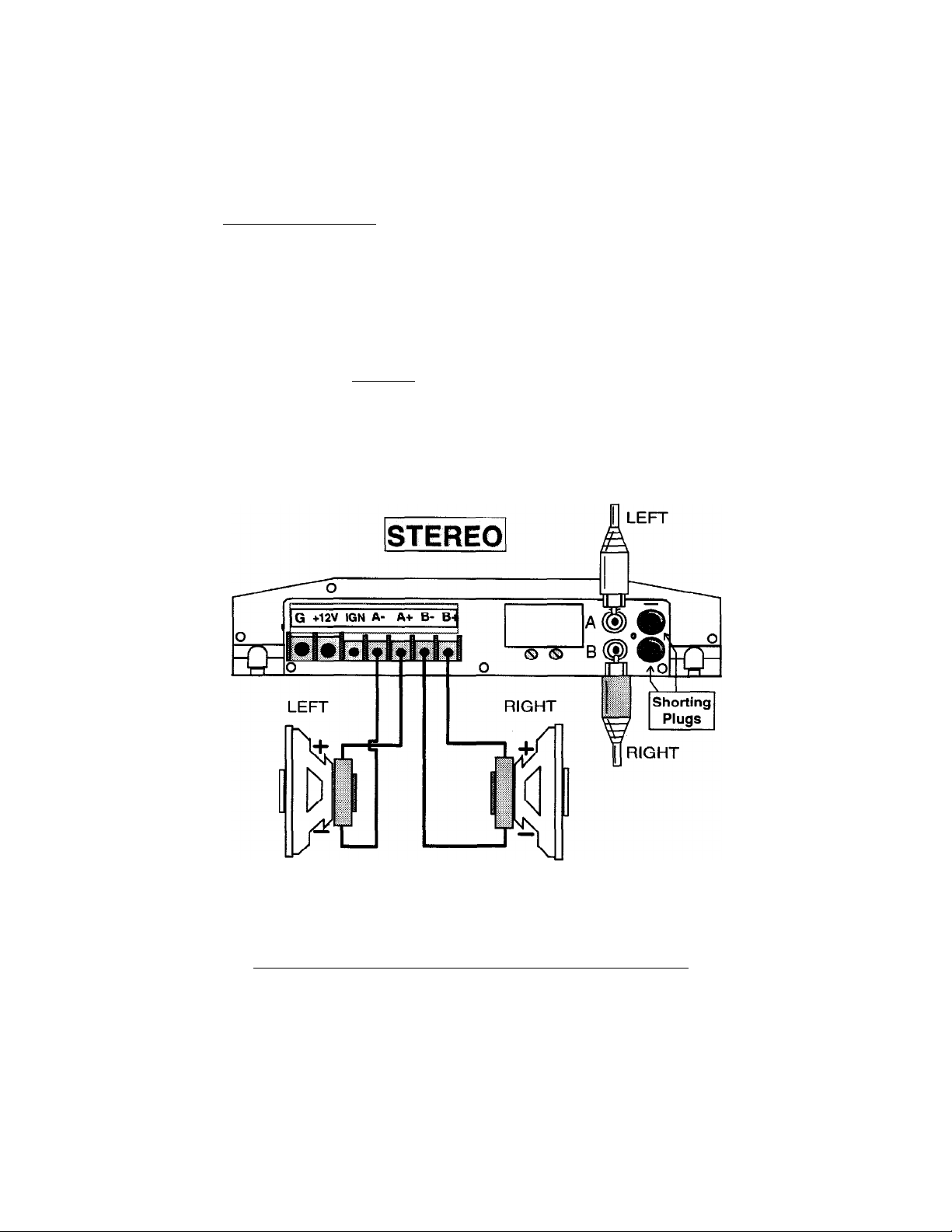
1. Stereo
2. Mono
3. Most™ (Mono/Stereo simultaneously)
In the Storoo mode, the RCA interconnect cables connect to the
Amplifier as follows: The left cable to A+ input and the right cable to B+ input.
Speakers hook up normally: "A+” and “A-” outputs to LEFT speaker(s) (+)pos &
(-)neg, and “B+" and “B-" outputs to the RIGHT speaker(s) (+)pos & (-)neg. See
Fig.2. Remember to insert the RCA Shorting Plugs in the unused inputs.
BE CERTAIN OF POWER/GROUND CONNECTIONS
Fig.2
Page 9

In the Mono mode, the LEF^" RCA cable connects to A+ input, the
RIGHT RCA cable connects to B- input. Remember to insert the RCA Shorting
Plugs in the unused inputs. The speaker outputs connect to the speaker as
follows: A+ output connects to the Positive(+) speaker terminal; B+ output
connects to the Negative(-) speaker terminal (see Fig. 3).
ACCOM car audio amplifiers are stable driving a 1 Ohm mono load, but
it is not recommended. For best results (maximum SPL and low THD), we
suggest a 2 or 4 Ohm mono load.
BE CERTAIN OF POWER/GROUND CONNECTIONS
Fig. 3
Page 10

In the Most™ configuration, the amplifier is capable of driving multiple
pairs of stereo speakers (properly crossed-over), and multiple mono
subwoofers, simultaneously!
To wire the MoSt™ configuration, connect the LEFT RCA to the A+
input; connect the RIGHT RCA to the B- input Remember to Insert the RCA
Shorting Plugs in the unused inputs. Wire speakers as shown in Fig. 4.
BE CERTAIN OF POWER/GROUND CONNECTIONS
Fig. 4
Page 11

SECTION 3: XLR Input Amps
For consistency, we suggest you use channels A and B ((eft most 5-pin
XLR) for Front Left and Right, and use channels C and D (right most 5-pin XLR)
for Rear Left and Right.
The GFA-4304, GFA-4404 and the GFA-4702 all use balanced inputs
terminated with professional 5-pin XLR connectors. Each 5-pin XLR connects
two channels (Left and Right)
straight-forward, but you must select the correct GFY adapter. The following
diagrams (Fig. 5), are a listing of all the adapters available through ADCOM for
integrating any system with ADCOM car audio amplifiers and interfaces. It is
of signal, plus a shield to the amplifier. Hookup is
vital to note the APPLICATION description! Specific adapters MUST
be used for specific applications!
>GFY ADAPTER CABLESE
Fig. 5 (part 1)
Page 12

>GFY ADAPTER CABLES <
continued
APPLICATION: Adapt XLRf2 ch.> input to accept stereo RCA-
tvpe input and run ¡n MONO or MoSt™ configuration.
"Right channel is inverted.
APPLICATION: Adapts XLRt2ch.) input to
RCA-tvpe source to run in STEREO
sf^.
—II ■■ ^1
■ Ug-
1 APPLICATION ;Converts a 4-channel ADCOM amc
1
to a Bridaed 2-channel amo (via GFX-2.5 or 20)
GFY-si
Fig. 5 (part 2)
Page 13

WIRING DIAGRAMS:
There are 9 wiring diagrams displayed on the following pages. Six are
basic single-amplifier wiring schemes, while one is a 2-amplifier, 5-channel
configuration using a GFA-4600 crossover/interface. Two are GFA-4702 wiring
schemes including the power cable connections.
There are many more possibilities using ADCOM car audio amplifiers,
but these are the most widely used configurations. Remember, the MoSt™
configuration may be combined with any other diagram to utilize the full
potential of ADCOM car audio amplifiers. If you have any questions or
confusion regarding these diagrams, PLEASE contact an authorized
ADCOM Car Audio Dealer or ADCOM Customer Service for technical
assistance. A listing of the diagrams follows;
Fig.
Fig.
Fig. 8
Fig.
Fig.
Fig.
Fig.
Fig.
Fig.
6
7
9
10
11
12
13
14
4-channels Stereo with GFI-4400 4- channels Stereo without GFI-4400 or GFI-4600
3-channels: 2-channels Stereo -t- 1-channel Mono
with GFI-4600
3-channels: 2-channels Stereo -i- 1-channel Mono
without GFI-4400 or GFI-4600
2-channels Stereo with GFI-4600 2-channels Stereo without GFI-4400 or GFI-4600
5- channel. 2-amp (XLR 4-channel and RCA 2-channel) with GFI-4600
2-channel Stereo GFA-4702 without GFI-4400 or GFI-4400
1-channel Mono GFA-4702 with GFI-4600
Page 14

Front/Rear Stereo (4 Ch.) with GFI-4400
O G [iS.7i=tf ■ > I □□
<1^
0000(1
_j ‘’PcMr Anttnna” or
RoarLm
I Front L/R
GFI-4400
Frort Rear g<D
B
|GFX-2.5 or 201
Rear
Front (A/B)
R Front —
R Front +
BE CERTAIN OF POWER/GROUND CONNECTIONS
0
n
«/ \i
Fig. 6
Page 15

Front/Rear Stereo (4 Ch.) without GFI-4400
BE CERTAIN OF POWER/GROUND CONNECTIONS
Fig. 7
Page 16

Front Stereo/Mono Sub (3 Ch.) with GFi-4600
O O 1 nn 1
\/\
|v
<l>
[DEIlHSCll
r i
IML
G FA-4304
or
GFA-4404
H
sue«
SUB +
Mono Sub
Left/Right(A/B)
The^xnperfor'Sub R*
is chan^ to inysit tha
Sub chann«l
ISUBi y' /
L R
?r
GFX-2.5
or 20
GFI-4600 //
S^l5] ¡l^e
Front Sub A® ^
vv
Controls
^ dI
He]
Polartty
Pin
Jignpers
Level
777T
tj
0
fi
U
BE CERTAIN OF POWER/GROUND CONNECTIONS
Fig. 8
Page 17

Front Stereo/Mono Sub (3 Ch.) without GF1-460Q
BE CERTAIN OF POWER/GROUND CONNECTIONS
Fig. 9
Page 18

Stereo (2 Ch.) with GFI-4600
Displayed as a Stereo Mids/Highs amp; Can be
used as Stereo Subwoofer amp, also.
BE CERTAIN OF POWER/GROUND CONNECTIONS
Fig. 10
Page 19

Stereo (2 Ch.) without GFI-4600
BE CERTAIN OF POWER/GROUND CONNECTIONS
Fig. 11
Page 20

Multi-Amp System using XLR and RCA
with GFI-4600
BE CERTAIN OF POWER/GROUND CONNECTIONS
Fig. 12
Page 21

GFA-4702 2-Channel without GFI-4400 or 4600
BE CERTAIN OF POWER/GROUND CONNECTIONS
Fig. 13
Page 22

GFA-4702 1-Channel (Mono) with GFI-4600
BE CERTAIN OF POWER/GROUND CONNECTIONS
Fig. 14
Page 23

AVAILABLE ACCESSORIES
ADAPTERS:
GFY-1 Adapts XLR Input to Mono RCA-type Input
GFY-2 Adapts XLR Output from GFI-4600 to RCA-
type Input of Amplifier
GFY-3 Adapts XLR Input to RCA-type Input to operate
Amplifier in the MoSt™ (or Mono) Configuration
GFY-4 Adapts XLR Input to RCA-type Input to operate
Amplifier in Stereo
GFY-5 Converts 4-Channel ACCOM Amplifier to
operate as a 2-Channel Amplifier
CABLES & MISCELLANEOUS:
GFX-2.5 30” 5-Pin Female XLR to XLR 2-Channel
Extension Cable (GFI to GFA)
GFX-20 20’ 5-Pin Female XLR to XLR 2-Channel
Extension Cable (GFI to GFA)
GFX-100 100’ roll of 5 Conductor Shielded Cable
GXL-F Female 5-Pin XLR Connector
GXL'M Male 5-Pin XLR Connector
GXL-R Right-Angle Female XLR 5-Pin Connector
GFC-5 5’ Power Interface Cable for GFA-4702
GFC-20 20’ Power Interface Cable for GFA-4702
GFM-xx Crossover Resister Modules for GFI-4600
(xx denotes frequency: 50, 60, 70, 85,120,150, 180,
200, 270, 400, 600 and 3350 Hz)
Page 24

/DCXM^
11 Elkins Road
E. Brunswick, NJ 08816
Phone (908) 390-1130
Fax (908) 390-5657
Copyright 1994
©Adcom Car Audio, Inc.
All Rights Reserved
djg694
 Loading...