

Page 1
Megabit Modem MM701G and MM702G
User Manual
Version 2.1.12.x
Catalog Number
MM701G-UM-01
Page 2

Copyright
April 2003
© 2003 ADC DSL Systems, Inc. All Rights Reserved.
Information contained in this document is company private to ADC DSL Systems, Inc., and shall not be modified, used,
copied, reproduced or disclosed in whole or in part without the written consent of ADC DSL Systems, Inc.
Trademark Information
ADC is a registered trademark of ADC Telecommunications, Inc. Megabit Modem is a registered trademark of ADC
DSL Systems, Inc. No right, license, or interest to such trademarks is granted hereunder, and you agree that no such
right, license, or interest shall be asserted by you with respect to such trademark.
Other product names mentioned in this documentation are used for identification purposes only and may be trademarks
or registered trademarks of their respective companies.
Disclaimer of Liability
Contents herein are current as of the date of publication. ADC reserves the right to change the contents without prior
notice. In no event shall ADC be liable for any damages resulting from loss of data, loss of use, or loss of profits, and
ADC further disclaims any and all liability for indirect, incidental, special, consequential or other similar damages. This
disclaimer of liability applies to all products, publications and services during and after the warranty period.
ii MM701G and MM702G User Manual
Page 3

About This User Manual
ABOUT THIS USER MANUAL
Use this manual to install, configure, and manage the ADC® Megabit Modem® MM701G and
MM702G. These modems can be used in two types of applications:
• as an endpoint (CPE) to a DSLAM for Internet and other broadband connection through a
service provider
• as a LAN extension by implementing a point-to-point connection with another modem of
the same model (MM701G to MM701G or MM702G to MM702G)
To complete an endpoint installation for an MM701G or MM702G modem, follow the
configuration instructions in all chapters of this manual, with the exception of Chapter 7,
“Implementing a Point-to-Point LAN Extension.”
To complete a point-to-point installation for two MM701G or two MM702G m odems, follow
the configuration instructions in these chapters only:
• Chapter 1, “Installing the Modem”
• Chapter 2, “Accessing the Web Interface for Modem Management”
• Chapter 5, “Configuring System Parameters”
• Chapter 7, “Implementing a Point-to-Point LAN Extension”
• Chapter 8, “Configuring Modem Security”
After configuring the modem(s) for your application, monitor its status and perform other
management functions using the instructions in Chapter 9, “Managing the Modem.” If you
choose to manage the modem through the console port, use the instructions in Appendix A,
“Accessing the Command-Line Interface.”
MM701G and MM702G User Manual iii
Page 4
Document Conventions
DOCUMENT CONVENTIONS
Notes contain information about special circumstances.
Cautions indicate the possibility of personal injury or equipment damage.
The following convention is used to identify the sequence of Web pages and/or menus you
navigate to access the feature configuration.
System
Password
The top grey bar indicates that the configuration parameter is
accessed from menu bar on the System Status page. For example,
select System on the menu bar, then select Password from the
System Options menu. The Web page from which you can change
the username and password is then displayed.
FCC CLASS B COMPLIANCE
This equipment has been tested and found to comply with the limits for a Class B digital device,
pursuant to part 15 of the FCC Rules. These limits are designed to provide reasonable protection
against harmful interference in a residential installation. This equipment generates, uses and can
radiate radio frequency energy and, if not installed and used in accordance with the instructions,
may cause harmful interference to radio communications. However, there is no guarantee that
interference will not occur in a particular installation.
If this equipment does cause harmful interference to radio or television reception, which can be
determined by turning the equipment off and on, the user is encouraged to try to correct the
interference by one or more of the following measures:
• Reorient or relocate the receiving antenna.
• Increase the separation between the equipment and receiver.
• Connect the equipment into an outlet on a circuit different from that to which the receiver
is connected.
• Consult the dealer or an experienced radio/TV technician for help.
iv MM701G and MM702G User Manual
Page 5

Table of Contents
TABLE OF CONTENTS
Chapter 1: Installing the Modem...........................................................................................1
Unpack the Modem ............................................................................................................1
Determine What You Need ................................................................................................ 2
Attach Feet to the Modem ..................................................................................................2
Connect Cables ...................................................................................................................3
Connect the 10Base-T Port ...................................................................................3
LED Status Indications ................................................................................ .........5
Chapter 2: Accessing the Web Interface for Modem Management....................................7
Assign IP Addresses ............................................. ..............................................................7
Set Up the Web Browser ....................................................................................................9
Accessing the Modem Web Pages ...................................... .................................. ............11
Chapter 3: Configuring the LAN.........................................................................................13
Before You Begin. . ........................................... .................................. .............................13
Configure the LAN............................................................................................................14
Configure DNS Relay Mode .............................................................................................16
Configure DHCP Server Mode .........................................................................................18
Configure the Ethernet Port Mode ....................................................................................23
Chapter 4: Configuring the WAN........................................................................................25
Before You Begin. . ........................................... .................................. .............................25
Configure a New WAN Session ........................................................................................26
Set Up an RFC 1483 Bridged Session................................................................27
Set Up an RFC 1483 Routed Session..................................................................29
Set Up a PPPoA or PPPoE Routed Session........................................................32
Permanently Save Sessions.................................................................................35
Edit a WAN Session..........................................................................................................36
MM701G and MM702G User Manual v
Page 6

Table of Contents
Chapter 5: Configuring System Parameters.......................................................................39
Before You Begin. . ................................................. .................................. .......................39
Assigning User Access ......................................................................................................40
Add a Default Gateway......................................................................................................44
Add Static Route Entries..................................................................... ...............................45
Add SNMP Communities.......... .................................................................... ....................48
Change Spanning Tree Setting .................................................................................... ......51
Saving Changes.................................................................. .................................. ..............53
Rebooting the Modem .......................................................................................................55
Chapter 6: Configuring DSL Parameters............................................................................57
Before You Begin. . ................................................. .................................. .......................57
Complete a G.shdsl Quick Configuration..........................................................................58
Complete a DSL Advanced Configuration........................................... .............................60
Chapter 7: Implementing a Point-to-Point LAN Extension...............................................63
Before You Begin. . ................................................. .................................. .......................63
Complete a Quick Installation ...........................................................................................64
Configure for Central-Office Mode ....................................................................64
Change the LAN IP Address for the Central-Office Modem..............................65
Complete a Custom Configuration....................................................................................66
Configure the Remote Modem............................................................................66
Configure the Central-Office Modem.................................................................70
Verify Connectivity .................................... ... .................................. ..................................76
Chapter 8: Configuring Modem Security............................................................................77
Before You Begin. . ................................................. .................................. .......................77
Configure NAT..................................................................................................................78
vi MM701G and MM702G User Manual
Page 7

Table of Contents
Chapter 9: Managing the Modem........................................................................................81
View System Status...................................................................................... ... ..................82
View Modem Status........................................ ....................................................82
View System Log......................................... ... .................................. ..................84
View WAN Statistics ............................................................... .........................................85
View LAN Statistics..................................... .................................. .................................. .87
View SmartCNCT Security Statistics ...............................................................................89
View ATM Statistics................ .................................. .................................. .....................90
View DSL Statistics ........................................................................................... ...............92
View G.shdsl Link Statistics.................................................. .............................92
View G.shdsl Error Counters..............................................................................9 4
Manage Software and Configuration.................................................................................96
Update System Software.....................................................................................96
Reset to Factory Defaults....................................................................................98
Appendix A: Accessing the Command-Line Interface........................................................99
Connect to the Console Port............................................................................................100
Access the Command-Line Interface ..............................................................................100
Access through the Console Port ......................................................................101
Access through a Telnet Session.......................................................................103
Set Up the LAN............................................................................................................... 104
Manage WAN Sessions...................................................................................................106
Add a New Session ...........................................................................................107
Permanently Save Sessions...............................................................................116
Edit an Existing Session....................................................................................117
Manage DSL....................................................................................................................118
Configure G.shdsl Parameters...........................................................................119
View G.shdsl Configuration..............................................................................124
Monitor G.shdsl Statistics................................................................................. 125
Restoring Factory Defaults..............................................................................................130
MM701G and MM702G User Manual vii
Page 8

Table of Contents
Saving the Current Configuration....................................................................................131
Updating System Software .......................................... ....................................................132
Viewing System Information...........................................................................................133
Rebooting the Modem .....................................................................................................134
Appendix B: Specifications ..................................................................................................135
Overview..........................................................................................................................136
Data Specifications..........................................................................................................137
VLAN Support ..................................................................................................137
DSL Standards...................................................................................................137
ATM standards..................................................................................................137
Internetworking Features...................................................................................137
WAN Protocols ....................................... .................................. ........................138
Security..............................................................................................................138
Management......................................................................................................138
Software Upgrade..............................................................................................138
Encapsulation ....................................................................................................139
RFCs..................................................................................................................139
MIBs..................................................................................................................140
Default Session Parameter Values ....................................................................140
Hardware Specifications..................................................................................................141
LED...................................................................................................................141
Connectors.........................................................................................................141
LAN Interface....................................................................................................141
WAN Interface ............................. .................................. .................................. .142
Connector Pinouts ........................................................................ .....................143
Rate vs. Reach..................................................................................................................145
Appendix C: Contacting ADC.............................................................................................147
Appendix D: Glossary...........................................................................................................149
Index.......................................................................................................................................155
viii MM701G and MM702G User Manual
Page 9
INSTALLING THE MODEM
The MM701G and MM702G are versatile, high-speed modems that connect an Ethernet LAN
to one or more service providers using G.shdsl transmission technology. The connections
provide instant and high-speed broadband access to the Internet or to other types of Wide Area
Networks (WANs). The MM701G and MM702G provide:
• configuration either as a point-to-point LAN extension or as an end-connection to a
DSLAM (see page iii for the process you must follow to complete either installation)
• larger packet sizes to accommodate VLAN traffic
• 32 simultaneous Bridge/Router or PPP sessions to the same or different service providers
over the WAN interface
• protocols and services such as DHCP server, DNS Relay, NAT, and RIP
• capability to download pre-defined configuration files to the modem flash memory instead
of manually defining each and every value for a modem
STEP 1—UNPACK THE MODEM
If you store the modem for a long period of time, use the original antistatic bag and packaging.
Observe environmental specifications provided in Appendix B.
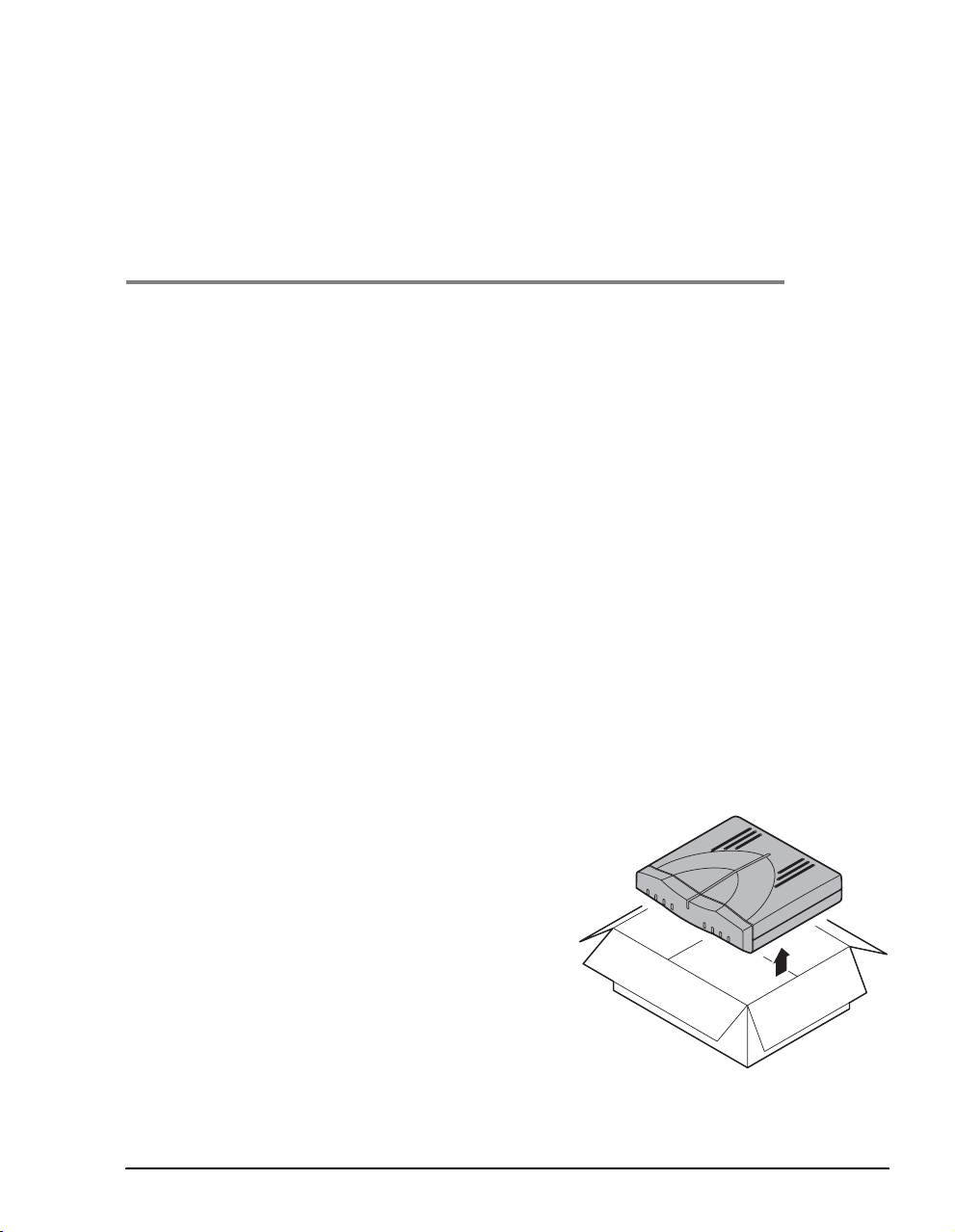
1 Remove the modem from the packaging.
1
2 Visually inspect the container for signs of
damage. If the equipm ent was damaged in
transit, report the damage to the transportation
company and to the sales representative.
L
IN
K
T
X
R
X
C
O
L
P
W
R
S
Y
N
C
T
X
R
X
M
A
R
3 Check the contents of the package for:
• 6 Vdc power supply with cord
• black Cat. 5 cable for Ethernet connection
• silver cord for DSL connection
M0151-A
• flat cable (gray) and DB-9 port adapter for
console port connection
MM701G and MM702G User Manual 1
Page 10

Determine What You Need
STEP 2—DETERMINE WHAT YOU NEED
In addition to what is shipped with the modem, you need the following hardware and software
to complete the installation and configuration.
Equipment: Requirement:
PC Hardware:
• Ethernet NIC Card (10 Mbps) installed in each PC and other network equipment
that will be connected to the LAN. Verify if the NIC in the device which directly
connects to the modem LAN port is half- or full-duplex. The modem LAN port
must be set to the same transmission direction(s) as the NIC.
• Optional—serial interface card installed in PC (used for access to the modem
console port).
Software:
• TCP/IP protocol stack installed (see the operating system documentation for
information).
• Terminal emulation program (such as HyperTerminal) installed for access to
the command line interface. through the console port (see the operating system
documentation for information).
®
Version 4.0 (or higher).
Ethernet hub, switch,
or router
• Web browser installed such as Internet Explorer
• Operating System CD-ROM (Win98, Win98SE, Win2000, WinME, or WinXP).
Optional—use either a hub, switch, or a router to connect multiple PCs or other
LAN equipment to the modem Ethernet 10Base-T port (LAN port).
STEP 3—ATTACH FEET TO THE MODEM
Attach oval rubber feet to the modem to prevent it from slipping on surfaces (a desktop, for
example) and from scratching those surfaces. Do the following:
1 Remove the paper from the adhesive back of the oval rubber feet.
2 Attach each of the four oval rubber adhesive-backed feet to a footprint recess on the bottom
of the modem.
2 MM701G and MM702G User Manual
Page 11
Chapter 1: Installing the Modem
r
STEP 4—CONNECT CABLES
Install cables for the Ethernet port (“Connect the 10Base-T Port” below). Then check LED
status on page 5.
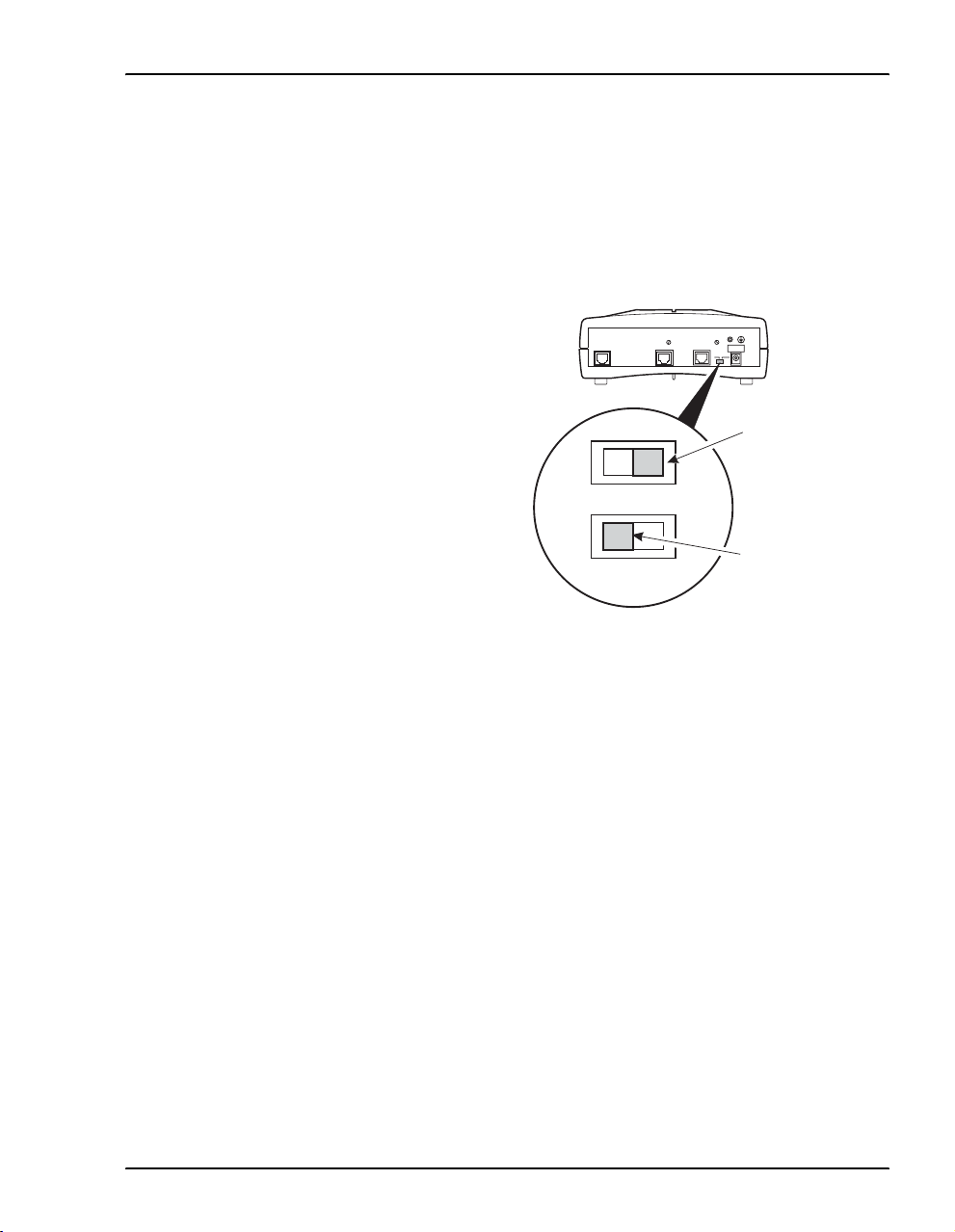
Connect the 10Base-T Port
Set the modem MDI/MDI-X switch for the
10Base-T port to allow the modem to connect
directly to other network devices such as a PC,
hub, switch, or router.
1 Set the modem MDI/MDI-X switch to one
of the following:
• MDI-X when connecting to a device
such as a PC Ethernet NIC card that
has an MDI port
MDI-X
M0325-A
For connection to
devices such as
a PC Ethernet NIC
• MDI when connecting to a device such
as a hub, switch, or router that have
MDI-X ports
MDI
For connection to
devices such as a
hub, switch, or route
MM701G and MM702G User Manual 3
Page 12
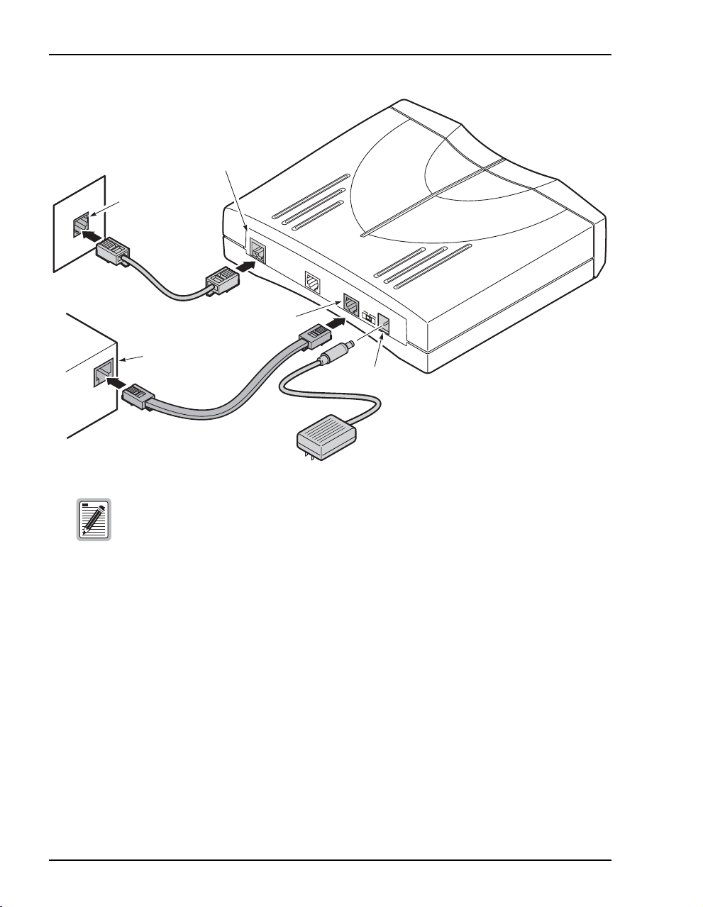
Connect Cables
DSL line
port
Wall jack with
DSL service
DSL LINE
CONSOLE
10BASE-T
POWER
M
D
I
M
D
I-X
Power
connector
M0152-B
PC, hub or other
network device
10Base-T
port
Ensure that the NIC in the PC and the modem LAN port are both set to either
half- or full-duplex for the transmission direction(s). If you need to change the
modem LAN port setting to match the NIC, follow the procedures in “Manage
DSL” on page 118 (half-duplex is the default).
2 Connect the cables to the modem rear panel as shown above:
• silver cable to the DSL line port and wall jack
• black Ethernet cable to the 10Base-T port and to another Ethernet device such as a PC,
hub, or router
• power cable to the modem power connector and to facility power
3 Refer to “LED Status Indications” on page 5, to check modem LED status indications.
4 MM701G and MM702G User Manual
Page 13

Chapter 1: Installing the Modem
LED Status Indications
The following indicates the operational status provided by front panel LEDs.
LED State Description
PWR On green Modem has power.
Off Modem does not have power.
LAN
LINK On green A PC, hub, or other network device is connected to the modem 10Base-T
Off No device is connected to the modem 10Base-T interface.
TX Flashing green Modem is transmitting data to devices on the LAN.
Off Modem is not transmitting data to the LAN.
RX Flashing green Modem is receiving data from devices on the LAN.
Off Modem is not receiving data from the LAN.
COL Flashing green Ethernet packet collisions are occurring.
Off No Ethernet packet collisions are occurring.
The service provider sets up the DSL parameters for your service. The modem must have the DSL SYNC LED
lit before you can connect sessions.
SYNC On green DSL transceiver is synchronized (connected) and in normal operation mode.
Flashing green Slow flashing green indicates that the DSL transceiver is in a start-up or
Off Power is not connected.
TX Flashing green Modem is transmitting data over the DSL connection.
Off Modem is not transmitting data over the DSL connection.
RX Flashing green Modem is receiving data over the DSL connection.
Off Modem is not receiving data over the DSL connection.
MAR On green Local SNR Margin is greater than the SNR Margin Limit.
Off Local SNR Margin is less than the SNR Margin Limit.
interface.
DSL
handshaking sequence. Fast flashing green indicates that the DSL
transceiver is in training sequence.
MM701G and MM702G User Manual 5
Page 14

Connect Cables
6 MM701G and MM702G User Manual
Page 15

ACCESSING THE WEB INTERFACE
FOR MODEM MANAGEMENT
Use the Web interface as the most comprehensive and convenient way to set up and manage the
modem. This chapter provides steps to help you access the Web interface pages for
configuration and management of the modem.
Access to the command-line interface is available through the modem console port or over
a network using a telnet session. Not all configuration and management features, however,
are s upp orted through the command-line interface. See Appendix A, “Accessing the
Command-Line Interface” on page 99 for instruction on using the command-line interface for
configuration and management.
STEP 1—ASSIGN IP ADDRESSES
To access the modem Web interface, the management PC must be on the same LAN IP subnet
as the modem. Default values are shown to the right. Do one of the following:
• Change the management PC IP address so that it is on the
same subnet as the modem (go to page 8 and begin with
Step 1).
• Change the IP address of the modem 10Base-T (LAN) port
to a value assigned by your network administrator using the
command-line interface (go to “Set Up the LAN” on
page 104).
Modem Defaults
Subnet 10.0.0.0
Subnet Mask 255.255.255.0
IP Address 10.0.0.1
2
MM701G and MM702G User Manual 7
Page 16
Assign IP Addresses
Use the following steps to set up a management PC to be on the same subnet with the modem.
(The example shows instructions for a PC that is running Microsoft Windows 98 SE;
instructions for other operating systems may differ slightly.)
1 From the Windows desktop, click
Control Panel dialog.
Start, Settings, Control Panel to open the
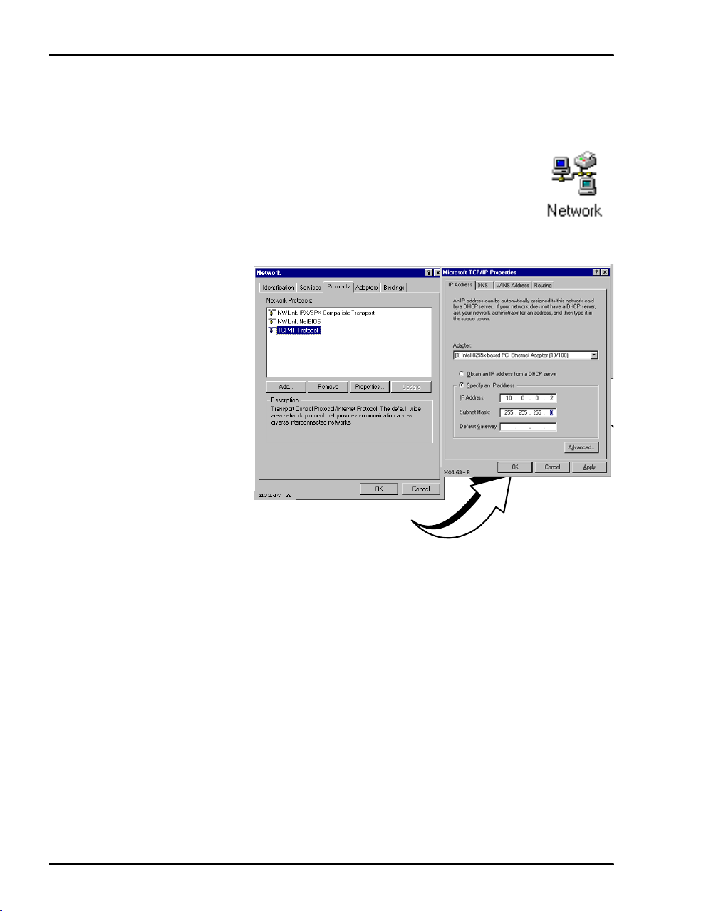
2 From the
right). The
3 From the
Control Panel dialog, double-click the Network icon (shown to the
Network dialog is displayed.
Configuration tab, double-click TCP/IP to display the TCP/IP Properties dialog.
TCP/IP Network Configuration
for an Ethernet NIC
4 The modem can be set up to serve IP addresses to devices on the LAN (DHCP server
feature). Do one of the following:
• If DHCP server has not been enabled on the modem (default setting), select
IP address
• If DHCP server has been enabled on the modem, select
automatically
5 Enter an
the modem.
.
Obtain an IP address
and go to Step 6.
IP Address and Subnet Mask that places the management PC on the same subnet as
Use an IP address in the range of 10.0.0.2 to 10.0.0.254.
Specify an
6 Click
7 Click
8 Click
8 MM701G and MM702G User Manual
OK to close the TCP/IP Properties dialog.
OK to close the Network dialog.
OK to restart the computer.
Page 17
Chapter 2: Accessing the Web Interface for Modem Management
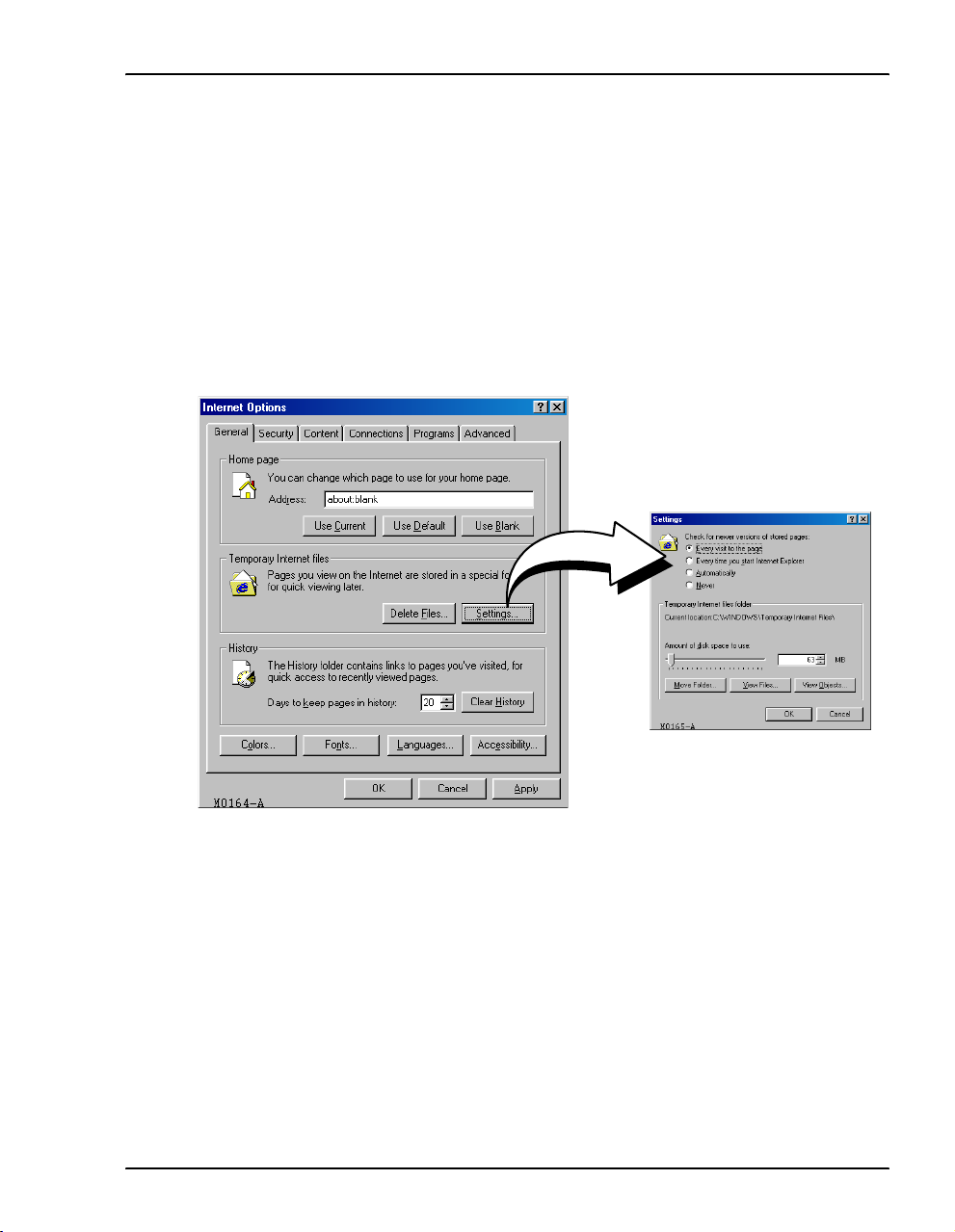
STEP 2—SET UP THE WEB BROWSER
To access and view the modem Web pages, set up features for the Web browser. The Web
browser must have cache settings enabled to allow the Web browser to compare its cached Web
page against the modem Web page every time it is accessed, providing current information.
Also, it is preferable to disable proxies. (The example below shows setup for the Internet
Explorer Web browser; instructions for other Web browsers may differ slightly.)
1 Open the Web browser.
2 On the menu bar, click
3 In the
4 Select
Temporary Internet Files section of the dialog, click Settings.
Every visit to the page, then click OK. (This sets enables cache settings.)
Tools, Internet Options to open the Internet Options dialog.
MM701G and MM702G User Manual 9
Page 18
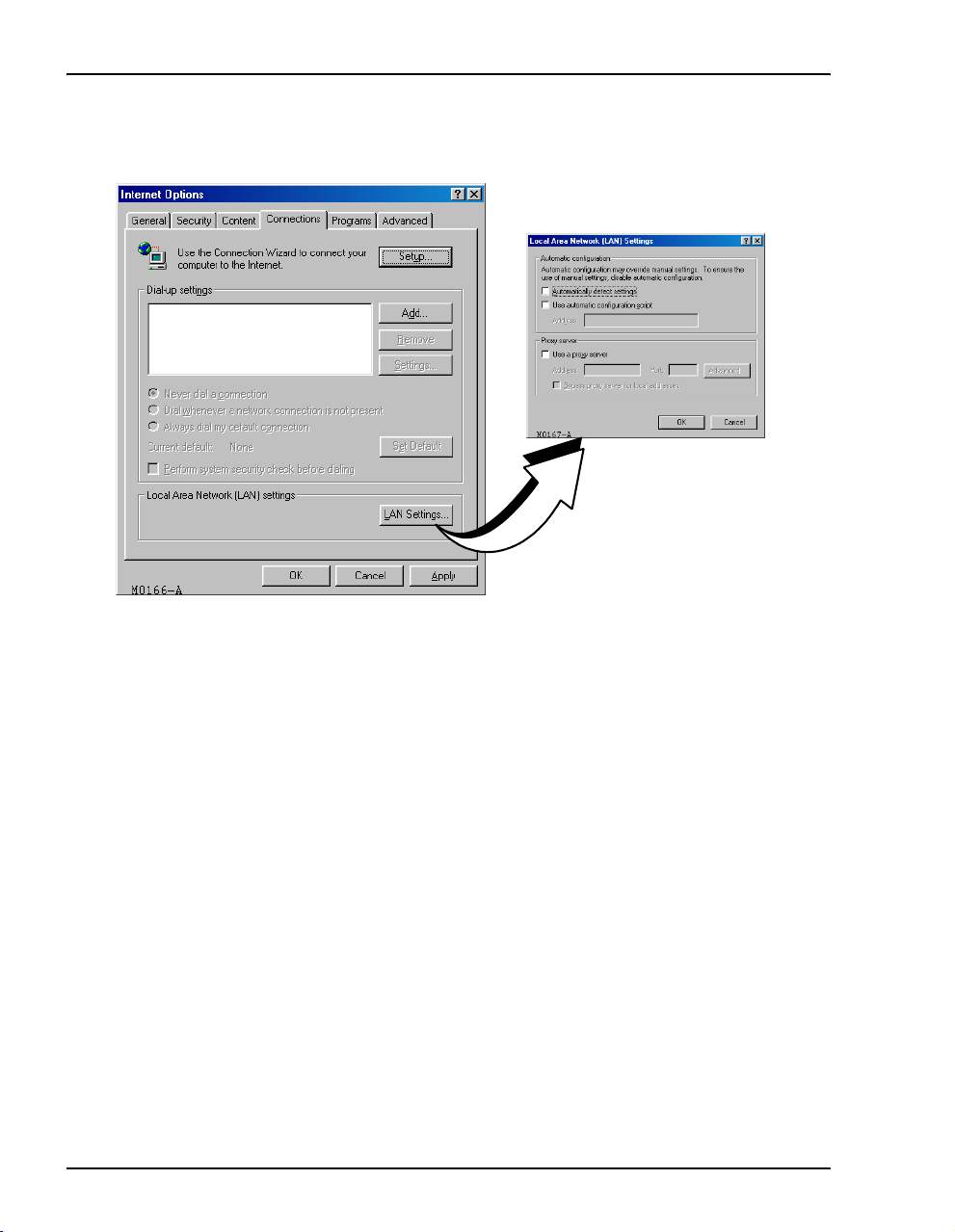
Set Up the Web Browser
5 Click the Connections tab, then click LAN Settings to open the LAN Settings dialog.
6 In the
Proxy Server section of the dialog, do one of the following:
• If the management PC is not connected to an intranet and is connected only to the
modem, clear the
Use a proxy server box.
• If the management PC is connected to the modem and also connected to an intranet
(with an assigned proxy server) using a hub, do the following:
– select the
– click
Exceptions field.
7 Click
8 Click
10 MM701G and MM702G User Manual
OK to close the LAN Settings dialog.
OK to close the Internet Options dialog.
Use a proxy server box
Advanced, then add the IP address of the modem (default is 10.0.0.1) to the
Page 19
Chapter 2: Accessing the Web Interface for Modem Management
STEP 3—ACCESSING THE MODEM WEB PAGES
Use the following steps to access the login page, enter the Web interface, and navigate the Web
pages. This login is for the system administrator responsible for configuring and managing the
modem.
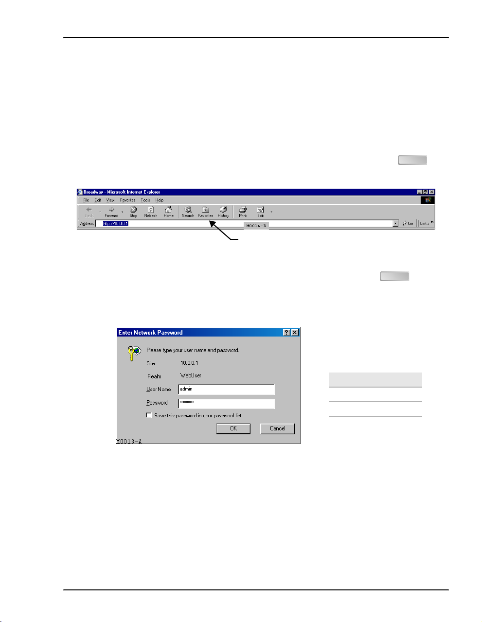
1 Do one of the following to access the modem Web pages:
• If you did not change the modem 10Base-T port IP address (page 7), type
in the Location Bar field of the Web browser (shown below), then press .
Location Bar
• If you changed the modem 10Base-T port IP address (page 7), type
IP address in the Location Bar field of the Web browser, then press .
2 Enter the
User Name and Password, then click OK.
Login Defaults
Username: admin
Password: password
http://10.0.0.1
ENTER
http:// and the new
ENTER
MM701G and MM702G User Manual 11
Page 20
Accessing the Modem Web Pages
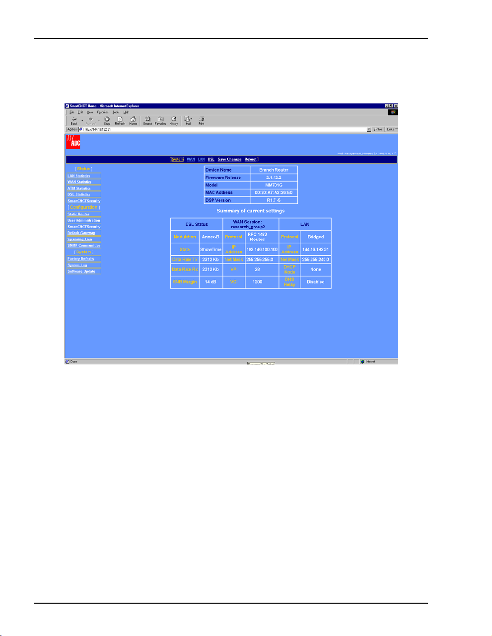
The System Status page is displayed and functions as a home page with a menu bar. This
menu bar provides navigation to all Web pages used for configuration and management.
Additionally, the
System Status page provides a status of the current modem configuration. See
“View System Status” in Chapter 9, “Managing the Modem” for more information about this
System Status page.
12 MM701G and MM702G User Manual
Page 21

CONFIGURING THE LAN
The LAN configuration sets up the interface between the modem 10Base-T LAN port and
devices on the LAN. The LAN is managed by your network administrator, who will make the
decisions concerning its topology.
For instructions on setting up the LAN interface for a point-to-point modem application, go to
Chapter 7, “Implementing a Point-to-Point LAN Extension.”
BEFORE YOU BEGIN. . .
Your network administrator will:
❑ Determine if you will use the modem Ethernet port in full- or half-duplex mod e .
❑ Identify a subnet value, including IP addresses and subnet masks.
❑ Determine if DHCP for the modem is enabled. If it is enabled, determine if th e modem will
be configured as a:
– DHCP client which receives an IP address fr om another device that is a DHCP server
on the LAN
3
– DHCP server (determine the range of IP addresses the modem will need to serve, and
identify the DHCP gateway and DNS server)
– DHCP relay agent (determine the IP address to which the DHCP functions will be
relayed)
❑ Determine if DNS Relay mode for the modem is enabled. If it is, identify the IP address for
the DNS server.
MM701G and MM702G User Manual 13
Page 22
Configure the LAN
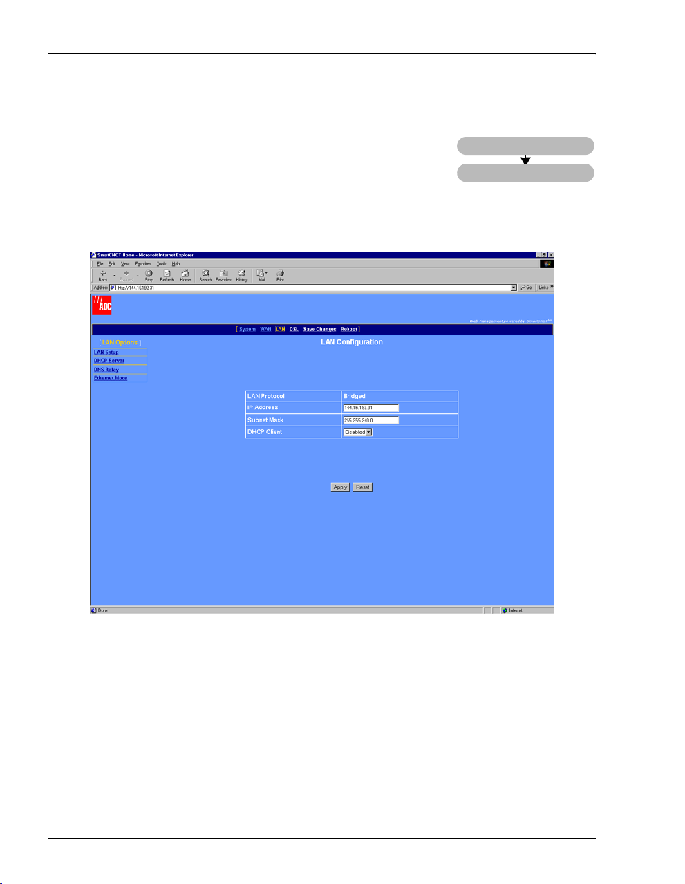
CONFIGURE THE LAN
From the LAN Configuration page, configure the parameters for the
LAN as indicated by your system administrator. The default protocol
for the LAN port is bridged.
1 Select
LAN on the menu bar, then select LAN Setup under [LAN Options] to access the LAN
Configuration
page.
LAN
LAN Setup
2 Configure the following parameters:
LAN Protocol
The LAN protocol is set to bridged and cannot be changed through the Web interface.
If you want to change the protocol to routed, use the command-line interface (go to
“Set Up the LAN” on page 104).
14 MM701G and MM702G User Manual
Page 23

Chapter 3: Configuring the LAN
IP Address
See the LAN administrator for a LAN IP address. Do one of the following:
• Enter an IP address for the LAN (10Base-T) port provided by the LAN
administrator
• Use the default IP address for the LAN port which is 10.0.0.1. If you choose to use
the default IP address, ensure that the devices on your LAN are on the same subnet
as this modem LAN port.
• If you want a DHCP server on your LAN to automatically provide the modem
LAN port IP address, select
Client for the DHCP configuration (see DHCP
Client below).
Subnet Mask
See the LAN administrator for the subnet mask. Do one of the following:
• Enter the subnet mask for the LAN (10Base-T) port provided by the LAN
administrator.
• Use the default subnet mask for the LAN port which is 255.255.255.0. If you
choose to use the default subnet mask, ensure that it allows devices on your LAN
to access the modem LAN port.
• If you want a DHCP server on your LAN to automatically provide the subnet mask
in addition to the IP address, select
Client for the DHCP configuration (see DHCP
Client below).
DHCP Client
If a DHCP server is not set up and active on your LAN, do not enable DHCP
client. DHCP Client mode is recommended for use only when bridging is used
as the LAN protocol.
A DHCP server must be set up and active on the LAN prior to enabling this feature.
When DHCP Client is
Enabled, the modem automatically changes the LAN port IP
address to all zeroes so that the DHCP server on the LAN can immediately serve it an
IP address. This parameter is used when the LAN port is in bridging mode only.
MM701G and MM702G User Manual 15
Page 24
Configure DNS Relay Mode
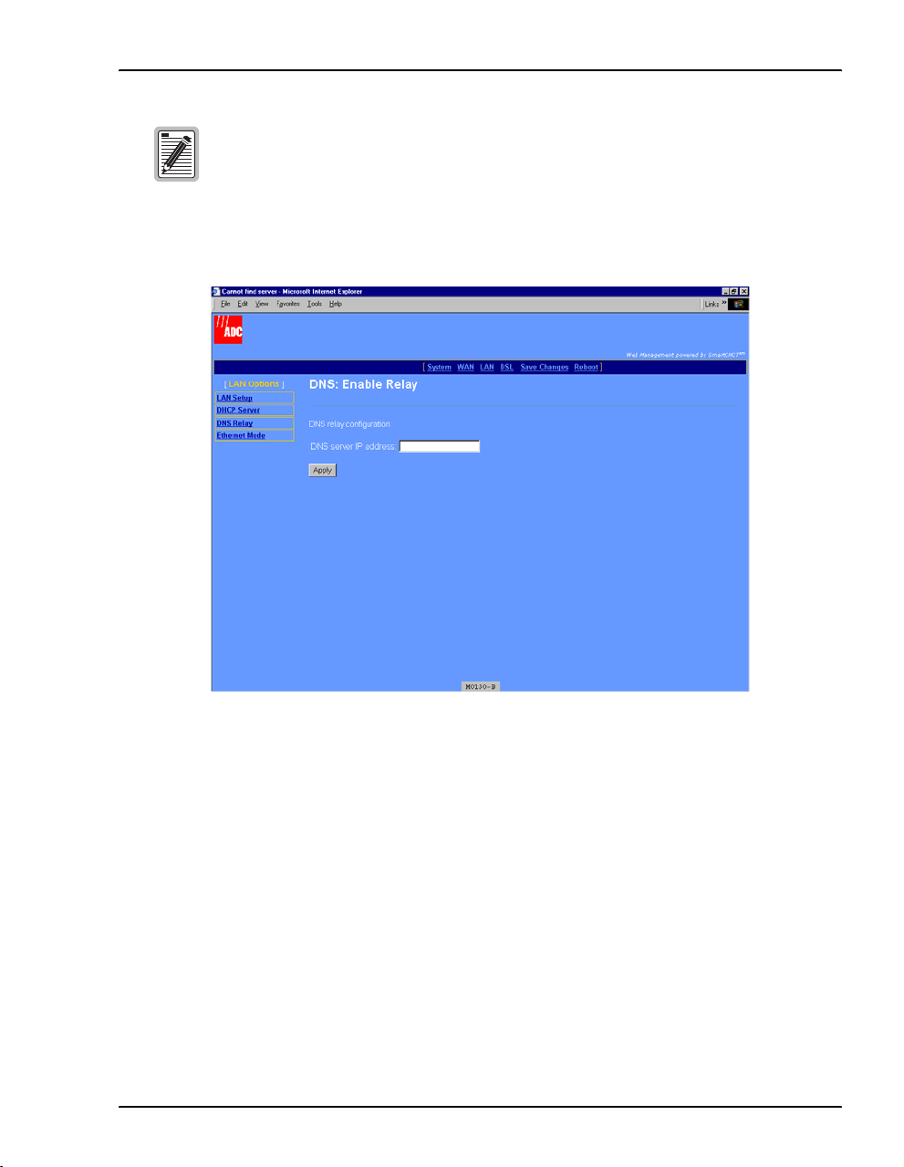
CONFIGURE DNS RELAY MODE
The DNS resolver on a DNS server maps human-readable addresses
LAN
to IP address numbers. A human-readable address is one such as:
maggie.copro.company.com
DNS Relay
As a DNS relay, the modem forwards requests for DNS resolution to another device on the LAN
or WAN that performs the resolution service. When you enable DNS Relay mode, enter the IP
address for the device that will perform DNS resolution. Either your service provider or LAN
administrator will provide this IP address.
If the modem is configured as a DHCP client (see “Configure the LAN” on page 14), it is served
a DNS address in addition to an IP address and subnet mask. The DNS relay will be
automatically enabled and the DNS server IP address will be automatically displayed in the
DNS server IP address field shown on page 17.
If you do not enable DNS relay nor do you enable DHCP client, then you must add the IP
address for a DNS resolver to the Internet Protocol (TCP/IP) setup for your PC (or other DHCP
client). See page 19 for more information on setting up this information.
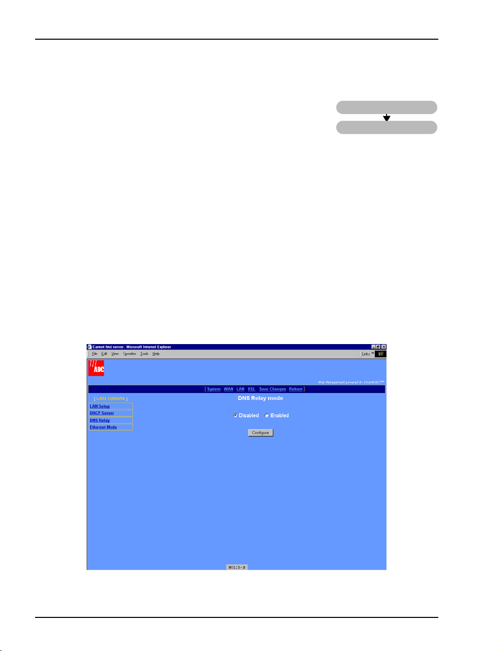
1 Select
LAN on the menu bar, then select DNS Relay under (LAN Options] to access the DNS
Relay mode
page.
16 MM701G and MM702G User Manual
Page 25
Chapter 3: Configuring the LAN
If DHCP Client is selected (see “Configure the LAN” on page 14) and a DNS
server IP address assigned, then DNS: Enable Relay is automatically enabled
and the DNS server IP address automatically displayed in that field.
2 Select Enabled, then click Configure to access the following DNS: Enable Relay page.
3 Enter the
DNS server IP address for the device to which the modem will forward IP address
resolution requests.
4 Click
MM701G and MM702G User Manual 17
Apply.
Page 26
Configure DHCP Server Mode
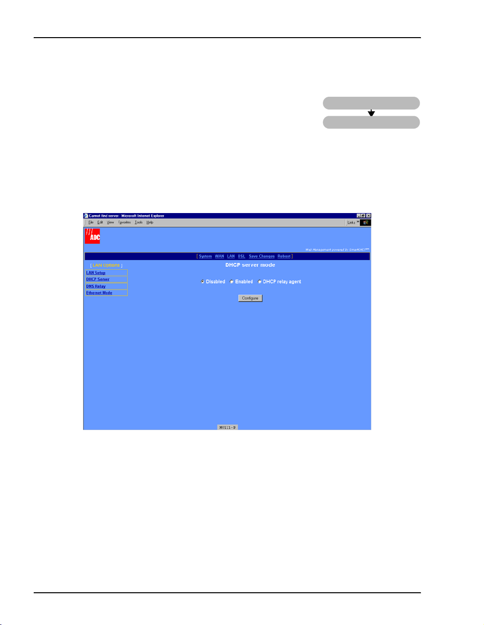
CONFIGURE DHCP SERVER MODE
From the DHCP server mode page, configure the parameters for the
modem to function as a DHCP server by either directly serving IP
addresses (DHCP server) or forwarding the request to another device
that will provide DHCP services (DHCP relay agent). If you selected
DHCP client when you configured LAN parameters (page 15), then
automatically set to
1 Select
LAN on the menu bar, then select DHCP Server under [LAN Options] to access the DHCP
server mode
Disabled.
page.
LAN
DHCP Server
DHCP server mode is
18 MM701G and MM702G User Manual
Page 27
Chapter 3: Configuring the LAN
2 Select one of the following three DHCP server modes as indicated by your LAN
administrator, then click
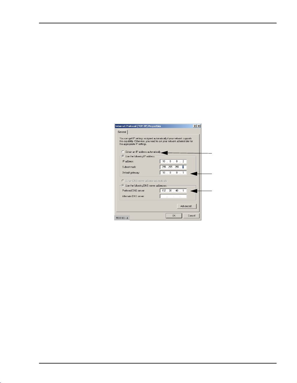
•
Disabled—DHCP server mode is not enabled. If you do not enable DHCP server for the
Configure:
modem, you must enter a default gateway for each client on your LAN (such as PCs)
and also an IP address for a DNS server. Either the service provider or your LAN
administrator will provide you these IP addresses to enter in the Internet Protocol
(TCP/IP) setup for your PC (or other LAN clients). See “Assign IP Addresses” on
page 7 for information about how to access this dialog. The following is an example
of the dialog and fields that must be filled in (example is from Windows 2000; the
dialog for other operating systems may be slightly different).
Set Internet protocol to: Use
the following IP address:
DHCP default gateway
IP address
DNS server IP address
MM701G and MM702G User Manual 19
Page 28
Configure DHCP Server Mode
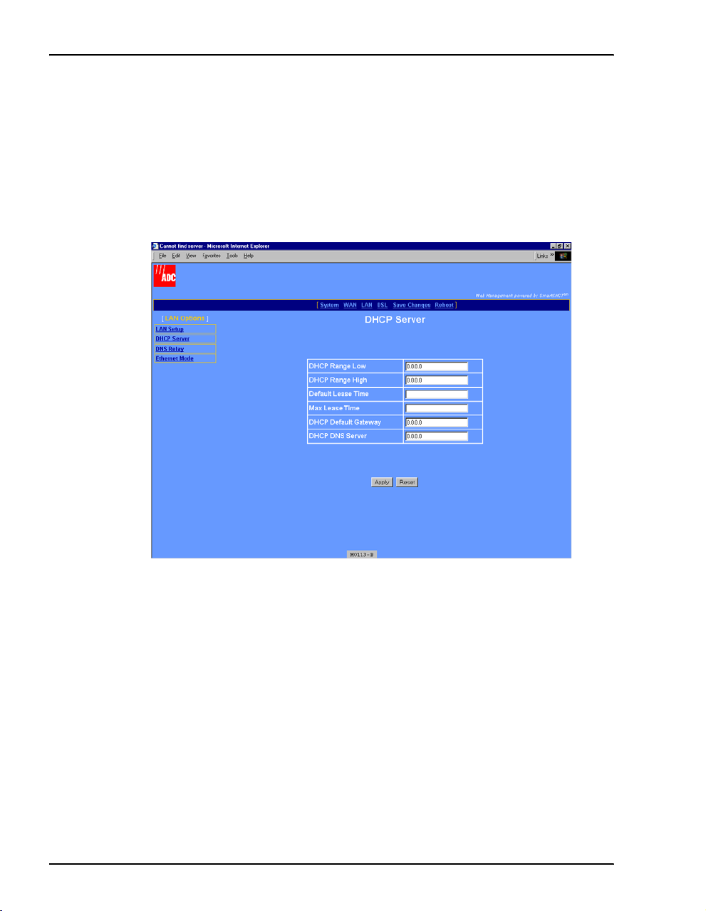
• Enabled—The modem functions as a DHCP server and can serve IP addresses, a DHCP
gateway, and a DNS server IP address to devices on your LAN. When the modem
DHCP server is enabled, then LAN clients (such as PCs) must have their Internet
protocol (TCP/IP) set to
Obtain an IP address automatically (see page 19 for an example
of where to select this option).
a Select
Enabled, then click Configure to access the following DHCP Server page
(DHCP Server cannot be enabled when the LAN protocol is in bridge mode).
b Configure the following parameters when DHCP server is enabled for the modem:
DHCP Range Low
The lowest IP address value that the modem can serve when configured as a
DHCP Server. A maximum of 20 IP addresses can be served by the modem.
This IP address value is provided by your LAN administrator and must be on
the same subnet as the modem LAN port.
DHCP Range High
The highest IP address value that the modem can serve when configured as a
DHCP Server. A maximum of 20 IP addresses can be served by the modem.
This IP address value is provided by your LAN administrator and must be on
the same subnet as the modem LAN port.
20 MM701G and MM702G User Manual
Page 29

Chapter 3: Configuring the LAN
Default Lease Time
The default amount of time, in seconds, that a device on the LAN can be
bound to the IP address it was served before the lease expires. This value is
provided by your LAN administrator.
Max Lease Time
The maximum amount of time, in seconds, that a device on the LAN can be
bound to the IP address it was served before the lease expires. This value is
provided by your LAN administrator.
DHCP Default Gateway
Enter the IP address of the DHCP default gateway that is provided by the
LAN administrator for devices on the LAN. After you configure this IP
address, the modem provides this IP address as a default DHCP gateway to
requesting DHCP clients (such as PCs) on the LAN. If there are no gateways
on the LAN, then the modem LAN port IP address can be assigned as the
gateway.
DHCP DNS Server
Enter the IP address of the Domain Name System (DNS) server that will
translate human-readable addresses to IP addresses. The DNS server can be
either on the LAN or the WAN side of the modem. The modem provides this
IP address as a default DNS server to requesting DHCP clients (such as PCs)
on the LAN. If the DNS server is on the LAN side of the modem, acquire the
IP address from your LAN administrator. If the DNS server is on the WAN
side of the server, acquire the IP address from the service provider.
If you enabled DNS relay on page 16 and entered a DNS server IP address,
then enter the modem LAN port IP address as the DHCP DNS server.
MM701G and MM702G User Manual 21
Page 30
Configure DHCP Server Mode
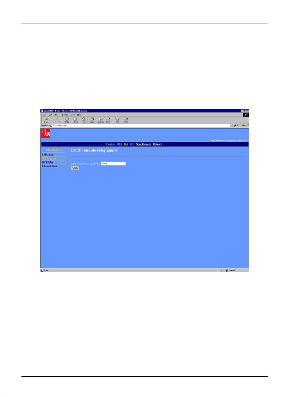
• DHCP relay agent— The modem forwards the request for an IP address, DHCP default
gateway, and DNS server IP address to a device acting as a DHCP server. The DHCP
server can be either on the LAN or the WAN side of the modem. If on the LAN side,
acquire the IP address from your LAN administrator. If on the WAN side, acquire the
IP address from the service provider.
a Select
page.
DHCP relay agent, then click Configure to access the following DHCP Server
b Enter the
DHCP services requests, then click
22 MM701G and MM702G User Manual
DHCP Server IP address for the device to which the modem will forward
Apply.
Page 31

Chapter 3: Configuring the LAN
CONFIGURE THE ETHERNET PORT MODE
The modem LAN (Ethernet) port must be set the same half- or
full-duplex mode as the NIC (or other Ethernet equipment) that
connects directly to it for management. Determine the mode to
which your NIC (or other Ethernet equipment) is set, then configure
the same mode for the modem LAN port.
1 Select
LAN on the menu bar, then select Ethernet Mode under LAN Options] to access the
Ethernet Mode page.
LAN
Ethernet Mode
2 Select either
MM701G and MM702G User Manual 23
Half Duplex or Full Duplex.
Page 32

Configure the Ethernet Port Mode
24 MM701G and MM702G User Manual
Page 33

CONFIGURING THE WAN
The WAN configuration sets up from 1 to 32 sessions between the modem and the service
provider or between two G.shdsl modems (see Chapter 7, “Implementing a Point-to-Point LAN
Extension” for more information). Each session can be configured separately, specifying the
protocol, IP address, ATM connection identifier, ATM QoS, and more.
BEFORE YOU BEGIN. . .
The following should be supplied by the service provider before configuring WAN sessions:
❑ Protocol for each session, where the choices are the following for a maximum of 32:
• RFC 1483-Bridge (up to 8 sessions)
• RFC 1483-Router (up to 16 sessions)
• PPPoA or PPPoE (up to 8 sessions for either type)
❑ IP address and subnet mask for each session using RFC 1483-Router protocol.
❑ RIP version (each direction) for each session using RFC 1483-Router protocol or PPP:
• RIP Version1
• RIP Version 2
• RIP Version 1 and RIP Version 2
❑ Encapsulation for 1483-Bridge or 1483-Router, where the choices are:
• LLC
• VCMux
4
❑ Login and authentication for each session using PPP protocol, where the choices are:
• login name and password
• authentication type of either PAP or CHAP
❑ ATM parameters for each session, including:
• VPI and VCI values
• Quality of Service (QoS) which could be UBR, CBR, or VBR-nrt, and VBR-rt, and
applicable cell rates
MM701G and MM702G User Manual 25
Page 34

Configure a New WAN Session
CONFIGURE A NEW WAN SESSION
You can configure up to 32 total PPPoA, PPPoE, 1483-Bridge, and
1483-Router sessions for the modem. See page 25 for the maximum
number of sessions per each protocol type that can be set up.
A defau lt bridging session is set up. From the WAN configuration
page, define the parameters for each session.
1 Select
WAN on the menu bar to access the WAN Configuration page.
WAN
WAN Setup
2 To add a new session, choose one of the following protocols from
•
RFC 1483 bridged if the modem forwards packets based on MAC addresses. You can
Select a new session type.
enable Spanning Tree when you select Bridge sessions. See “Change Spanning Tree
Setting” on page 51.
•
RFC 1483 routed if the modem routes packets based on IP addresses.
•
PPPoA routed if the modem establishes PPP sessions over ATM with the service
provider and routes packets based on IP addresses.
•
PPPoE routed if modem establishes PPP sessions over Ethernet with the service
provider and routes packets based on IP addresses.
3 Click
Configure to access the session page for the protocol type you selected.
4 Go to the appropriate section that follows for the protocol that you selected.
26 MM701G and MM702G User Manual
Page 35

Chapter 4: Configuring the WAN
Set Up an RFC 1483 Bridged Session
You selected RFC 1483 bridged from the WAN Configuration page to display the following page.
1 Configure the following parameters for each session:
Session Name
Enter a unique, descriptive identifier for the session. This name can have a maximum
of 32 characters.
Virtual Path ID (VPI)
Enter the value (from 0 to 4,095) provided by the service provider. The number
identifies the virtual path that transports ATM cells between the modem and the
service provider. This value must match the virtual path identification (VPI) value
the service provider uses for this connection.
Virtual Channel ID (VCI)
Enter the value (from 32 to 65,535) provided by the service provider. The number
identifies the virtual channel for this session that transports ATM cells between the
modem and the service provider. This value must match the virtual channel
identification (VCI) value the service provider uses for this connection.
MM701G and MM702G User Manual 27
Page 36

Configure a New WAN Session
ATM QoS
Select the ATM Quality of Service indicated by your service provider. The options are:
• UBR (unspecified bit rate is the default setting)
• CBR (constant bit rate)
• VBR-rt (variable bit rate real-time)
• VBR-nrt (variable bit rate non-real-time)
QoS Peak Cell Rate
Enter the QoS Peak Cell Rate (PCR) value supplied by your service provider. If you
are not provided a PCR value, use the default. PCR is the maximum rate at which data
is transferred on the line and measured in ATM cells per second. The valid range is
1-5500 cells per second. The default PCR is 5500.
QoS Sustainable Cell Rate
Enter the QoS Sustainable Cell Rate (SCR) value supplied by your service provider.
Use for VBR-rt, and VBR-nrt ATM QoS. SCR is the average rate at which ATM cells
are transferred, measured in cells per second. The SCR must be less than the PCR. The
valid range is 1-5500 cells per second.
QoS Maximum Burst Size
Enter the QoS Maximum Burst Size (MBS) value supplied by your service provider.
Use with VBR-rt and VBR-nrt QoS. MBS is the maximum number of cells that can be
transmitted at the peak cell rate. The MBS rate must be equal to or less than the PCR.
The default MBS is 0.
Encapsulation
Select the encapsulation type as indicated by the service provider. The options are:
•
LlcBridged—Logical Link Control allows multiple protocols to be run over the
session. This is the default encapsulation.
•
VcMuxBridged—Virtual Channel Multiplexer-based encapsulation allows one
protocol to be run over the session.
2 Click
28 MM701G and MM702G User Manual
Create to add the new RFC1483-Bridge session to your session list on the WAN
Configuration
page.
Page 37

Chapter 4: Configuring the WAN
Set Up an RFC 1483 Routed Session
You selected RFC 1483 routed from the WAN Configuration page to display the following page.
1 Configure the following parameters for each session:
Session Name
Enter a unique, descriptive identifier for the session. This name can have a maximum
of 32 characters.
Virtual Path ID (VPI)
Enter the value (from 0 to 4,095) provided by the service provider. The number
identifies the virtual path that transports ATM cells between the modem and the
service provider. This value must match the virtual path identification (VPI) value
the service provider uses for this connection.
Virtual Channel ID (VCI)
Enter the value (from 32 to 65,535) provided by the service provider. The number
identifies the virtual channel for this session that transports ATM cells between the
modem and the service provider. This value must match the virtual channel
identification (VCI) value the service provider uses for this connection.
MM701G and MM702G User Manual 29
Page 38

Configure a New WAN Session
ATM QoS
Select the ATM Quality of Service indicated by your service provider. The options are:
• UBR (unspecified bit rate is the default setting)
• CBR (constant bit rate)
• VBR-rt (variable bit rate real-time)
• VBR-nrt (variable bit rate non-real-time)
QoS Peak Cell Rate
Enter the QoS Peak Cell Rate (PCR) value supplied by your service provider. If you
are not provided a PCR value, use the default. PCR is the maximum rate at which data
is transferred on the line and measured in ATM cells per second. The valid range is
1-5500 cells per second. The default PCR is 5500.
QoS Sustainable Cell Rate
Enter the QoS Sustainable Cell Rate (SCR) value supplied by your service provider.
Use for VBR-rt, and VBR-nrt ATM QoS. SCR is the average rate at which ATM cells
are transferred, measured in cells per second. The SCR must be less than the PCR. The
valid range is 1-5500 cells per second.
QoS Maximum Burst Size
Enter the QoS Maximum Burst Size (MBS) value supplied by your service provider.
Use with VBR-rt and VBR-nrt QoS. MBS is the maximum number of cells that can be
transmitted at the peak cell rate. The MBS rate must be equal to or less than the PCR.
The default MBS is 0.
Encapsulation
Select the encapsulation type as indicated by the service provider. The options are:
•
LlcRouted—Logical Link Control allows multiple protocols to be run over the
session. This is the default encapsulation.
•
VcMuxRouted—Virtual Channel Multiplexer-based encapsulation allows one
protocol to be run over the session.
30 MM701G and MM702G User Manual
Page 39

Chapter 4: Configuring the WAN
DHCP Client
Select to enable DHCP client where this session will automatically received an IP
address from the service provider via a DHCP server. If you select DHCP client, leave
the next two fields, IP address and Subnet Mask, blank. These fields will automatically
receive values.
IP Address
Enter the IP address provided by the service provider for this session. Or if DHCP
Client was selected, the IP address will automatically be assigned by a DHCP server
on the WAN side of the network. The default IP address is 0.0.0.0.
Subnet Mask
Enter the subnet mask provided by the service provider for this session or use the
default subnet mask for the session which is 255.0.0.0. Or if DHCP Client was
selected, the subnet mask will automatically be assigned by a DHCP server on the
WAN side of the network.
RIP Send
This session forwards RIP version 1 (Ver 1), RIP version 2 multicast (Ver2 (M-cast)),
RIP version 2 broadcast (
version or versions the modem will send on this session. The default is
Ver2 (B-cast)), or all versions of RIP packets. Select the RIP
Ver2 (B-cast).
RIP Accept
This session receives RIP version 1 (Ver 1) only, RIP version 2 (Ver 2) only, or both
versions of RIP packets. Select the RIP version or versions the modem will receive for
this session. The default is RIP
2 Click
MM701G and MM702G User Manual 31
Create to add the new RFC1483-Router session to your session list on the WAN
Configuration
page.
Ver 1 and Ver 2.
Page 40

Configure a New WAN Session
Set Up a PPPoA or PPPoE Routed Session
You selected either PPPoA routed or PPPoE routed from the WAN Configuration page to display the
following page. The
configuration parameters for
PPPoA routed configuration page is shown below as an example. The
PPPoE routed are identical.
1 Configure the following parameters for each session:
Session Name
Enter a unique, descriptive identifier for the session. This name can have a maximum
of 32 characters.
Virtual Path ID (VPI)
Enter the value (from 0 to 4,095) provided by the service provider. The number
identifies the virtual path that transports ATM cells between the modem and the
service provider. This value must match the virtual path identification (VPI) value
the service provider uses for this connection.
32 MM701G and MM702G User Manual
Page 41

Chapter 4: Configuring the WAN
Virtual Channel ID (VCI)
Enter the value (from 32 to 65,535) provided by the service provider. The number
identifies the virtual channel for this session that transports ATM cells between the
modem and the service provider. This value must match the virtual channel
identification (VCI) value the service provider uses for this connection.
ATM QoS
Select the ATM Quality of Service indicated by your service provider. The options are:
• UBR (unspecified bit rate is the default setting)
• CBR (constant bit rate)
• VBR-rt (variable bit rate real-time)
• VBR-nrt (variable bit rate non-real-time)
QoS Peak Cell Rate
Enter the QoS Peak Cell Rate (PCR) value supplied by your service provider. If you
are not provided a PCR value, use the default. PCR is the maximum rate at which data
is transferred on the line and measured in ATM cells per second. The valid range is
1-5500 cells per second. The default PCR is 5500.
QoS Sustainable Cell Rate
Enter the QoS Sustainable Cell Rate (SCR) value supplied by your service provider.
Use for VBR-rt, and VBR-nrt ATM QoS. SCR is the average rate at which ATM cells
are transferred, measured in cells per second. The SCR must be less than the PCR. The
valid range is 1-5500 cells per second.
QoS Maximum Burst Size
Enter the QoS Maximum Burst Size (MBS) value supplied by your service provider.
Use with VBR-rt and VBR-nrt QoS. MBS is the maximum number of cells that can be
transmitted at the peak cell rate. The MBS rate must be equal to or less than th e PCR.
The default MBS is 0.
MM701G and MM702G User Manual 33
Page 42

Configure a New WAN Session
LLC Header
Select either true or false for the LLC header. The default is false. False indicates that
VCMux encapsulation is used. True indicates that LLC/Snap encapsulation is used.
IP Address
The IP address is dynamically served by the service provider for this session. When
the modem has received the IP address for this session, it displays the value in this
field. Also, the IP address dynamically received for the first PPP session set up is
assigned as the default gateway (see page 44).
If the service provider does not dynamically provide an IP address, they can give you
a static IP address that you can enter in this field.
Subnet Mask
The subnet mask is dynamically served by the service provider for this session. The
default subnet mask for the session is 0.0.0.0.
If the service provider does not dynamically provide a subnet mask, they can give you
a subnet mask value that you can enter in this field.
RIP Send
This session forwards RIP version 1 (Ver 1), RIP version 2 multicast (Ver2 (M-cast)),
RIP version 2 broadcast (
version or versions the modem will send on this session. The default is
RIP Accept
Ver2 (B-cast)), or all versions of RIP packets. Select the RIP
Ver2 (B-cast).
This session receives RIP version 1 (Ver 1) only, RIP version 2 (Ver 2) only, or both
versions of RIP packets. Select the RIP version or versions the modem will receive for
this session. The default is RIP
Authentication
Ver 1 and Ver 2.
Select the authentication protocol provided by your service provider for PPP sessions.
The authentication protocol type must match at the modem and the service provider.
The options are:
•
PAP—The modem sends authentication requests to the service provider and
authentication occurs only once during the life of the DSL link.
•
CHAP—The service provider returns an authentication challenge to the modem
during the authentication (default setting).
•
NONE—No authentication is required for the session.
34 MM701G and MM702G User Manual
Page 43

Chapter 4: Configuring the WAN
Login
Change the default login name (admin) for this PPP session to the Login name supplied
by the service provider. Minimum login name length is one character and the
maximum is 32 characters.
Password
Change the default login password (password) for this PPP session to the Login
password supplied by the service provider. Minimum password length is six characters
and the maximum is 32 characters.
2 Click
Create to add the new PPPoA or PPPoE session to your session list on the WAN
Configuration
page.
Permanently Save Sessions
After you have set up all the WAN sessions, save these changes permanently as described in
Chapter 5, “Saving Changes.”
MM701G and MM702G User Manual 35
Page 44

Edit a WAN Session
EDIT A WAN SESSION
You can change parameters for any of the 32 PPPoA, PPPoE,
1483-Bridge, and 1483-Router sessions for the modem. See page 25
for the limits on sessions per each protocol type. From the WAN
configuration page, configure the parameters for each session you
will set up.
1 Select
WAN on the menu bar to access the WAN Configuration page.
WAN
WAN Setup
36 MM701G and MM702G User Manual
Page 45

Chapter 4: Configuring the WAN
2 Select a session from the [WAN Sessions] list. The configuration options for that WAN
session is displayed.
The following shows the fields you can edit for a routing session or you can delete the
session. The
Protocol field at the top of the dialog is read-only. It indicates the protocol that
you previously selected for this session.
MM701G and MM702G User Manual 37
Page 46

Edit a WAN Session
The following shows the fields you can edit for a PPP session or you can delete the session.
The
Protocol field at the top of the dialog is read-only. It indicates the protocol that you
previously selected for this session.
3 Change session parameters as required. Go to the following pages for parameter definitions
based on the protocol used for that session:
• For an RFC1483-Bridge session, go to page 27.
• For an RFC1483-Routed session, go to page 29.
• For a PPPoA Routed session, go to page 32.
• For a PPPoE Routed session, go to page 32.
4 Do one of the following:
• Click
• Click
Apply, then save changes as described in Chapter 5 , “Saving Changes.”
Delete to entirely remove the session, then save changes as described in
Chapter 5, “Saving Changes.”
38 MM701G and MM702G User Manual
Page 47

CONFIGURING
SYSTEM PARAMETERS
These configuration parameters affect system functions for the modem. Other system
parameters used to manage or troubleshoot the modem (updating modem software, for
example) are in Chapter 9, “Managing the Modem.”
BEFORE YOU BEGIN. . .
Determine the following before changing system parameters:
❑ If secured management access is required for the modem, add users and assign one of three
predefined security levels: Default, Engineer, or Super User.
❑ If SNMP authentication is required, add SNMP communities with either read or write
access.
❑ Add the IP address for the network default router through which packets are forwarded.
❑ If static routes will be used to predetermined destinations, identify the destination host or
network IP address. Also, identify the next hop gateway IP address for devices on your
LAN (for example, the modem LAN port IP address).
❑ If spanning tree protocol is required, based on one or both of the following conditions, then
enable it:
– RFC 1483-Bridge protocol is used for any session or for the 10Base-T port (LAN)
– there are multiple bridging devices on a LAN with more than one physical path
connecting them and you want to prevent loops
5
Otherwise, disable spanning tree protocol.
MM701G and MM702G User Manual 39
Page 48

Assigning User Access
ASSIGNING USER ACCESS
The modem provides secure access for managing and viewing
System
modem configuration. Three levels of access are predefined and can
be assigned to users you set up. These security logons are required
User Administration
for access to the Web interface or to access the command-line
interface through either the console port or through a telnet session.
For the three levels of predefined access, it is recommended that you change the passwords for
all three accesses to secure the modem for management. The following procedures show how
to add, modify, or delete user accounts.
1 Select
System on the menu bar, then select User Administration under [Configuration] to access
the
Users’ List page.
40 MM701G and MM702G User Manual
Page 49

Chapter 5: Configuring System Parameters
2 To add a new user account, do the following:
a Click
Add a new user. The following dialog is displayed.
It is important to change the password for all three default user accounts to
ensure secure access to modem for configuration and management.
b Enter the following information:
User Name
The login name for this user. The login name can
be a maximum of 32 characters and all keyboard
characters, except a space, are allowed.
Password
The password associated with this user login.
The password must be a minimum of six and a
maximum of 32 alphanumeric characters
User Name admin
Password password
Access level superuser
User Name isp
Password password
Access level engineer
User Name user
Password password
Access level default
Defaults
(including caps and lowercase).
MM701G and MM702G User Manual 41
Page 50

Assigning User Access
Access Level
The level of access to modem configuration and management allowed for this
user. Choose from the following access levels.
Access Level Definition
Super User This user has full administrative access to the modem. This
Engineer This user has write access to all LAN-side and DSL configuration
Default This user has view only access to all modem configuration and
Comment
includes full view and write access to all modem configuration
and management.
(including DSL testing) only. All other configuration access
(WAN session and System) is view only.
management. Default is the default access level when setting up
new user accounts.
Identifies the user in a way that is meaningful to you. All keyboard characters
are allowed.
c Click
Add. The new entry is added to and is displayed in the Users’ List table (see
page 40).
42 MM701G and MM702G User Manual
Page 51

Chapter 5: Configuring System Parameters
3 To modify or delete an existing user entry, do the following:
It is important to change the default password for all three default user
accounts to ensure secure access to modem for configuration and
management.
a From the
Users’ List table (see page 40), select the name in the User column that you
want to change or delete. The following dialog is displayed.
b To modify the user account, change any of the parameters. Click
Apply.
c To delete the user account, click Delete. The user account is immediately removed from
the
Users’ List table.
MM701G and MM702G User Manual 43
Page 52

Add a Default Gateway
ADD A DEFAULT GATEWAY
The modem default gateway is a IP address through which packets
System
are routed to the internet if the next hop IP address cannot be
identified by the modem. Use either the IP address of a WAN session
Default Gateway
or 0.0.0.0 (default value).
When setting the modem default gateway, if the first session you set up was a PPP session, the
IP address that was dynamically assigned to that PPP session was also automatically assigned
as the default gateway. If you do not want this IP address (PPP WAN session) as the default
gateway, then use this page to change it to another value.
1 Select
System on the menu bar, then select Default Gateway under [Configuration] to access the
Default Gateway page.
2 To add a default gateway, enter the IP address for the gateway through which the modem
will forward packets. Click
3 To remove the default gateway IP address, click
44 MM701G and MM702G User Manual
Apply.
Delete.
Page 53

Chapter 5: Configuring System Parameters
ADD STATIC ROUTE ENTRIES
A static route provides a defined path from one host or network to a
destination host or network. This type of route is manually entered
as a fixed path, as contrasted to a dynamic route which is
automatically determined and learned (RIP, for example). If the next
gateway for network traffic is unknown, a static route will be its default path.
1 Select
System on the menu bar, then select Static Routes under [Configuration] to access the
Static Routes page.
System
Static Routes
MM701G and MM702G User Manual 45
Page 54

Add Static Route Entries
2 To add a new static route, do the following:
a On the
Static Routes page, click Create a new IP route. The following dialog is displayed.
b Enter the following information for the static route.
Destination
The IP address for the destination network, subnet, or host to which the packets
are directed. Use 0.0.0.0 as the destination IP address for a default route.
Gateway
The IP address for the next hop in your network to which the packets are
forwarded. For example, if your network is connected either directly or through a
hub to the LAN port of the modem, then the LAN port IP address can be the next
hop. Or, a WAN port can be the next hop for traffic.
Netmask
The network mask defining the route and access for the destination IP address.
46 MM701G and MM702G User Manual
Page 55

Chapter 5: Configuring System Parameters
Cost
The number of hops (gateways) from 1 to 15 through which this traffic can pass
before reaching its destination.
c Click
Create. The new entry is added to and is displayed in the Static Routes table (see
page 45).
3 To delete a static route entry, do the following:
a From the
Static Routes table (page 45), click the IP address in the Destination column
that you want to delete. The following dialog is displayed.
b Click
MM701G and MM702G User Manual 47
Delete to remove the static route entry or click Cancel to stop the operation and
return to the
Static Routes table.
Page 56

Add SNMP Communities
ADD SNMP COMMUNITIES
An SNMP community provides the authentication and authorization,
through its community string, to view and/or change modem
parameters.
1 Select
System on the menu bar, then select SNMP Communities under [Configuration] to access
the
SNMP Community List page. Go to step 2 to add an SNMP community or go to step 3 to
change or delete an existing SNMP community.
System
SNMP Communities
48 MM701G and MM702G User Manual
Page 57

Chapter 5: Configuring System Parameters
2 To add a new SNMP community, do the following:
a On the
displayed.
SNMP Community List page, click Add a new community. The following dialog is
b Enter the following information for the SNMP community.
Name
Identification for this SNMP community. All keyboard characters are allowed for
this name, up to a maximum of 80 characters. You must add a community name
in this field to later edit or delete the SNMP community. This name in the
Community List
Access Privilege
table provides the link for editing or deleting the entry.
SNMP
The access allowed to this SNMP community. Accesses are either Read
c Click
(view-only access) or
Add. The new entry is added to and is displayed in the SNMP Community List table
Write (full view and write access).
(see page 48).
MM701G and MM702G User Manual 49
Page 58

Add SNMP Communities
3 To modify or delete an SNMP community, do the following:
a From the
dialog is displayed.
SNMP Community List table, select the SNMP community Name. The following
b Do one of the following:
– Change the
Access Privilege, then click Apply.
– Click Delete to remove the static SNMP community.
50 MM701G and MM702G User Manual
Page 59

Chapter 5: Configuring System Parameters
CHANGE SPANNING TREE SETTING
Spanning tree eliminates loops in a LAN topology, ensuring that
System
there is only one path (or link) between any two nodes in a network.
Use spanning tree protocol (STP) when RFC 1483-Bridge protocol
Configuration
is assigned to either or both of the following:
• WAN sessions (see “Configure a New WAN Session” on page 26)
• LAN port and the LAN has more than one device (PCs and servers, for example) and those
devices have more than one physical path connecting them.
The default spanning tree setting is disabled. Access spanning tree configuration as follows:
1 Select
System on the menu bar, then select Spanning Tree under [Configuration] to access the
Bridge Spanning Tree page.
2 Enter the following parameters to enable STP for bridging sessions:
Spanning Tree
Select Enable to activate the STP for all RFC 1483-Bridge sessions. Disable turns
off STP for all modem bridging sessions.
MM701G and MM702G User Manual 51
Page 60

Change Spanning Tree Setting
Priority
The modem STP priority (how centrally located this bridge is) in the network. A
lower number indicates a more centrally located bridge. The valid priority range
is 0 to 65535. A priority of 32768 is the default value.
Hello Time
The time interval in seconds at which the modem should send STP packets.
Default value is 2 seconds.
Forward Delay
The time interval in seconds that should be waited until the state of an interface
can change. This delay prevents interface states from changing so rapidly that STP
cannot keep up with the current network topology and therefore cannot efficiently
managing bridging. Default value is 15 seconds.
Max Age
The time interval in seconds after which Spanning Tree entries that are not
relearned are deleted from the bridging table. Default value is 20 seconds.
52 MM701G and MM702G User Manual
Page 61

Chapter 5: Configuring System Parameters
SAVING CHANGES
Use the Save Changes page for saving your current configuration to
Save Changes
flash memory. This option immediately writes all current system
configuration to permanent memory (NVRAM). You cannot selectively write configuration to
NVRAM. When you issue the save command, all current configuration is written to NVRAM.
When saving the modem configuration, do not power off the modem while the
save is in process.
1 Select
Save Changes on the menu bar to access the Save Changes page.
MM701G and MM702G User Manual 53
Page 62

Saving Changes
2 Do one of the following:
• Click
Save to write the configuration to flash memory and do not power off the modem
while the save is in progress. The following dialog is displayed when the save is
completed.
• Click
54 MM701G and MM702G User Manual
Cancel to exit the current page without saving your configuration.
Page 63

Chapter 5: Configuring System Parameters
REBOOTING THE MODEM
Before rebooting the modem, save any configuration changes you
have made using the steps in “Saving Changes” on page 53.
1 Select
Reboot on the menu bar to access the Reboot page.
Reboot
2 Do one of the following:
• Click
• Click
MM701G and MM702G User Manual 55
Yes to reboot the modem.
No to cancel the rebooting process.
Page 64

Rebooting the Modem
56 MM701G and MM702G User Manual
Page 65

CONFIGURING DSL PARAMETERS
The DSL parameters set up the G.shdsl communication between the modem and a DSLAM or
between two modems used in a point-to-point application. Typically, the DSL parameters for
the modem are preset to immediately synchronize with the service provider (DSLAM
application). However, you may be instructed to make changes to the DSL configuration. This
chapter provides information for setting G.shdsl parameters when the modem is in an
application as a DSLAM endpoint. For instruction on setting up G.shdsl parameters for a
point-to-point modem application, go to Chapter 7, “Implementing a Point-to-Point LAN
Extension.”
BEFORE YOU BEGIN. . .
The following are configurable DSL parameters for the G.shdsl modem; change parameters
only when instructed to do so by the service provider or your system administrator.
❑ The operating mode choices are Remote (use when the modem is an endpoint for a DSLAM
application or the customer-side modem in a point-to-point application) or Central-Office
(use only for the central office-side modem in a point-to-point application)
❑ Annex A or B provides the appropriate operating characteristics for G.shdsl, dependent on
your geographical location.
6
❑ A margin value, in decibels, that must be met to initialize modem.
❑ Either fixed or adaptive mode that the modem will use to negotiate the best transmission
rate at which both ends of the connection can synchronize.
❑ Wire pair mode, either Single (two-wire) or Dual (four-wire), can be selected only for the
MM702G modem. The MM701G modem is used only in Single mode.
❑ PSD mask is either symmetric or asymmetr ic. The values used to calculate the asymmetric
mask are dependent on the Annex A or B you selected.
MM701G and MM702G User Manual 57
Page 66

Complete a G.shdsl Quick Configuration
COMPLETE A G.SHDSL QUICK CONFIGURATION
Configure basic operating parameters for the modem.
1 Select
DSL on the menu bar, then select Quick Configuration under
[DSL Options].
Quick Configuration
2 Configure the following parameters as directed by your service provider:
Operating Mode
When the modem is connected to a service provider through a DSLAM, the operating
mode is
Remote (default setting).
DSL
When two modems are used in a point-to-point application (LAN extension, for
example), one modem at the customer or user site is set to
modem in the CO or wiring closet is set to
Central-Office. For instruction on setting up
Remote and the second
G.shdsl parameters and other related parameters for a point-to-point modem
application, go to Chapter 7, “Implementing a Point-to-Point LAN Extension.”
Standard Annex
Select one of the following Annexes:
•
Annex-A for operating conditions typically found in the North American
implementation of G.shdsl
•
Annex-B for operating conditions typically found in the European implementation
of G.shdsl. This is the default mode for the MM701G modem.
58 MM701G and MM702G User Manual
Page 67

Chapter 6: Configuring DSL Parameters
• Auto for automatically negotiating the Annex A or B standard by which this
modem, and the device to which this modem is attached, can operate. This is the
default mode for the MM702G modem.
•
Annex-B_ANFP for operating conditions that include the Annex B standard with
Access Network Frequency Plan Pulse Spectral Density (PSD) mask.
•
Auto_ANFP for automatically negotiating the Annex A or B standard with Access
Network Frequency Plan Pulse Spectral Density (PSD) mask.
Startup Margin
Bit Rate Mode
3 Click
The target signal-to-noise margin, in decibels, that the modem must achieve with a
BER of 10
-7
or better to successfully complete synchronization. The default margin
value is 6 dB. A lower margin may result in a higher data rate, but it can increase noise
on the line. Possible values are
-10dB through 10dB, or to completely Disable the
margin.
Bit rate mode indicates how the modem synchronizes with the device to which it is
attached in either a
Fixed mode. The default for the MM701G modem is Adaptive mode.
•
Fixed mode indicates that the modem will synchronize with the other end (a
Fixed or Adaptive mode. The default for the MM702G modem is
DSLAM or another modem) at a fixed bit rate through negotiation. The modem
will synchronize at the best rate, up to the data rate specified (page 61), that can
be achieved by both ends.
•
Adaptive mode indicates that prior to modem negotiating a rate, the modem
performs an adaptation phase during which it determines a best possible rate based
on conditions of the line. After adaptive mode, the modem will then negotiate the
best rate that can be achieved with the other end, based on the adaptation results.
Apply.
MM701G and MM702G User Manual 59
Page 68

Complete a DSL Advanced Configuration
COMPLETE A DSL ADVANCED CONFIGURATION
Configure the G.shdsl parameters for the modem to facilitate it
synchronizing with either a DSLAM or another modem to which it
attaches.
1 Select
DSL on the menu bar, then select Advance Configuration under [DSL Options].
Advance Configuration
2 Configure the following parameters as directed by your service provider:
Operating Mode
DSL
When the modem is connected to a service provider through a DSLAM, the operating
mode is
Remote (default setting).
When two modems are used in a point-to-point application (LAN extension, for
example), one modem at the customer or user site is set to
modem in the CO or wiring closet is set to
Central-Office. For instruction on setting up
Remote and the second
G.shdsl parameters and other related parameters for a point-to-point modem
application, go to Chapter 7, “Implementing a Point-to-Point LAN Extension.”
Standard Annex
Determines the transmission standards to which this G.shdsl connection will comply.
The Annex standard should be the same at both ends of the connection. Select one of
the following Annexes:
•
Annex-A for operating conditions typically found in the North American
implementation of G.shdsl
60 MM701G and MM702G User Manual
Page 69

Chapter 6: Configuring DSL Parameters
• Annex-B for operating conditions typically found in the European implementation
of G.shdsl. This is the default mode for the MM701G modem.
•
Auto for automatically negotiates the Annex A or B standard by which this modem,
and the device to which this modem is attached, can operate. This is the default
mode for the MM702G modem.
•
Annex-B_ANFP for operating conditions that include the Annex B standard with
Access Network Frequency Plan Pulse Spectral Density (PSD) mask.
•
Auto_ANFP for automatically negotiating the Annex A or B standard with Access
Network Frequency Plan Pulse Spectral Density (PSD) mask.
Startup Margin
The target signal-to-noise margin, in decibels, that the modem must achieve with a
BER of 10
-7
or better to successfully complete synchronization. The default margin
value is 6 dB. A lower margin may result in a higher data rate, but it can increase noise
on the line. Possible values are
-10dB through 10dB, or to completely Disable the
margin.
Data Rate (kbps)
Data rate determines the maximum transmission rate, in kilobits per second, up to
which the modem can negotiate and synchronize with another device (modem or a
DSLAM) to which it is attached. When the
Bit Rate Mode (page 62) is set to Fixed, the
range of values are (ADC modems comply with the standard G.shdsl data rate range):
• for the MM702G modem, 384 kbps to 4608 kbps, in 128 kbps increments (default
value is 4608)
• for the MM701G modem, 192 kbps to 2304 kbps, in 64 kbps increments
Rates down to 64 kbps are supported only when operating in single-pair,
point-to-point mode with another ADC modem. (see Chapter 7, “Implementing a
Point-to-Point LAN Extension”).
When the
MM701G default value) or for an MM702G set to
below)
cannot be used in
Bit Rate Mode (page 62) is set to Adaptive for an MM701G (Adaptive is
Single Wire Pair Mode only (see
, this field is automatically set to Adaptive. An MM702G in Dual Wire Pair Mode
Adaptive Bit Rate Mode.
Wire Pair Mode
Indicates whether the G.shdsl modem is operating in a two-wire mode (Single) or a
four-wire mode (
available. For the MM702G modem, you can select either
Dual mode is the default.
MM701G and MM702G User Manual 61
Dual). For the MM701G modem, Single mode is the only setting
Single or Dual mode and
Page 70

Complete a DSL Advanced Configuration
Power Spectrum Distribution
The Power Spectral Density (PSD) plots the variations of signal power with signal
frequency for the G.shdsl transmission between the modem and the DSLAM or the
modem and another modem.
Symmetric PSD indicates that the PSD mask for both sides
of the transmission (the CO- and remote-side) are the same (symmetric).
Asymmetric PSD indicates that the PSD mask for both sides of the transmission
(the CO- and remote-side) are not the same (asymmetric). There are two unique
numeric values (
AsymmetricRate1 and AsymmetricRate2) used to determine the
asymmetric PSD mask based on the Annex A or Annex B standard that you selected
(see page 60).
AsymmetricRate2 is 1552 kbps for Annex A and 2056 kbps for Annex B.
AsymmetricRate1 is 784 kbps for Annex A and 2312 kbps for Annex B.
Both ends of the connection must be set for th e same Symmetr ic or Asymmetric PSD.
The default is
Bit Rate Mode
Symmetric.
Bit rate mode indicates how the modem synchronizes with the device to which it is
attached in either a
Fixed mode. The default for the MM701G modem is Adaptive mode.
•
Fixed mode indicates that the modem will synchronize with the other end (a
Fixed or Adaptive mode. The default for the MM702G modem is
DSLAM or another modem) at a fixed bit rate through negotiation. The modem
will synchronize at the best rate, up to the data rate specified (page 61), that can
be achieved by both ends.
•
Adaptive mode indicates that prior to modem negotiating a rate, the modem
performs an adaptation phase during which it determines a best possible rate based
on conditions of the line. After adaptive mode, the modem will then negotiate the
best rate that can be achieved with the other end, based on the adaptation results.
An MM702G in
Test Bit Rate
Dual Wire Pair Mode cannot be used in Adaptive Bit Rate Mode.
This bit rate is used by the manufacturer for internal use only.
SNR Margin Limit
Identifies the minimum SNR margin (in decibels) that must exist when the G.shdsl
connection is synchronized and in order for the DSL MAR LED to be lit ON Green.
The range of values is -64 to 63. The default value is 4.
3 Click
62 MM701G and MM702G User Manual
Apply then save changes using “Saving Changes” on page 53.
Page 71

IMPLEMENTING A POINT-TO-POINT
LAN EXTENSION
Two ADC G.shdsl modems can be implemented in a point-to-point application (also called
back-to-back). In this application, the modems can be used to connect remote LANs to
create L AN extensions. In this point-to-point application, one ADC G.shdsl modem is set to
Remote mode and the other ADC G.shdsl modem is set for Central-Office mode. By bridging
traffic between these two modems, you essentially create one extended LAN that allows the use
of a single IP subnet.
Although you can set up multiple sessions on these modems, only one RFC 1483-Bridge
sessions is required for implementing a point-to-point LAN extension.
The ADC modems comply with the standard G.shdsl data rate range of 192 kbps to 2304 kbps.
Additionally, rates down to 64 kbps are supported only when using the G.shdsl modem in
single-pair, point-to-point mode for a LAN extension application.
BEFORE YOU BEGIN. . .
Determine which of these implementations apply for your application:
❑ Quick Install—If your application does not require custom configuration, you can use the
default modem settings. To implement, the Remote mode modem is already configured
with factory default configuration for implementing point-to-point LAN extension; no
changes are necessary for this modem to impl ement service. The Central-Office modem
requires only two configuration changes to set the modem to Central-Office mode. These
changes are described in “Complete a Quick Installation” on page 64.
7
❑ Custom Configuration—If you implement custom configuration where you do not use
factory default parameters for your modems, refer to “Complete a Custom Configuration”
on page 66 to configure the Remote modem and to configure the Central-Office modem.
MM701G and MM702G User Manual 63
Page 72

Complete a Quick Installation
COMPLETE A QUICK INSTALLATION
The modem is shipped with factory defaults as a Remote modem and does not
require any additional configuration when used as a remote. Only the
Central-Office modem requires configuration changes.
In a quick installation, you change configuration only for the Central-Office mode modem. The
Remote modem uses its factory default parameters. To set up the Central-Office modem, follow
the instructions in the following sections. The modems use a default bridging WAN session
(
RFC1483-bridged) which has a predefined ATM connection using Virtual Path ID of 0 and
Virtual Channel ID of 35.
Configure for Central-Office Mode
1 Select DSL on the menu bar, then select Advance Configuration under [DSL Options].
2 In the
3 Click
64 MM701G and MM702G User Manual
Operating Mode box, select Central-Office to set up this modem for this mode.
Apply.
Page 73

Chapter 7: Implementing a Point-to-Point LAN Extension
Change the LAN IP Address for the Central-Office Modem
Because the Central-Office and Remote modems are on the same IP subnet in this point-to-point
application, you must change the IP address for the Central-Office modem.
1 Select
LAN on the menu bar to access the LAN Configuration page.
2 In the IP address box, enter
10.0.0.2.
Any device (such as a PC) connecting to the modem LAN interface loses its
connection when the modem LAN IP address is changed. After the IP address
is changed, you need to specify this new address in the Web browser to
reconnect a device.
3 Click
Apply to activate the changes. The connection to the Web interface will be lost
because the modem now has a new LAN IP address.
4 In the Web browser address field (see page 11), specify
5 Click
Save Changes on the menu bar to prevent losing the configuration after restoring
http://10.0.0.2 to reconnect.
communication with the modem.
You are now finished with the Quick Installation. To verify connectivity, refer to “Verify
Connectivity” on page 76
MM701G and MM702G User Manual 65
Page 74

Complete a Custom Configuration
COMPLETE A CUSTOM CONFIGURATION
If you implement custom configuration where you do not use factory default parameters for
your modems, you will need to make changes to the configuration on both the Remote and the
Central-Office modem. The following sections provide configuration changes for the Remote
modem and then for the Central-Office modem.
Configure the Remote Modem
To configure the remote modem, you need to change the following settings:
• operating mode for the modem, (see “Configure the Remote Operating Mode” on page 66)
• WAN parameters, (see “Configure the Remote WAN” on page 67)
• LAN parameters, (see “Configure the Remote LAN” on page 69)
Configure the Remote Operating Mode
1 Select DSL on the menu bar then select Advance Configuration under [DSL Options].
2 In the
3 Click
66 MM701G and MM702G User Manual
Operating Mode box, select Remote to configure the modem for this mode.
Apply.
Page 75

Chapter 7: Implementing a Point-to-Point LAN Extension
Configure the Remote WAN
1 Select WAN on the menu bar to access the WAN Configuration page.
MM701G and MM702G User Manual 67
Page 76

Complete a Custom Configuration
2 Select RFC 1483 bridged from the WAN Configuration page to display the following page.
3 In the
4 In the
Session Name box, assign a name to this session.
Virtual Path ID (VPI 0 - 4,095) box, enter the Virtual Path ID. This must match the
Virtual Path ID of the Central-Office modem.
5 In the
Virtual Channel ID (VCI 32 - 65,535) box, enter the Virtual Channel ID. This must match
the Virtual Channel ID of the Central-Office modem.
6 Click
68 MM701G and MM702G User Manual
Apply.
Page 77

Chapter 7: Implementing a Point-to-Point LAN Extension
Configure the Remote LAN
1 Select LAN on the menu bar, then select LAN Setup under LAN Options] to access the LAN
Configuration
page.
2 In the
LAN Protocol box, confirm that the protocol is set to Bridged. If the protocol is not set
to bridged, it can be changed only through the command-line interface. See Appendix A,
“Accessing the Command-Line Interface” for procedures on using this interface to change
the LAN protocol.
Any device (such as a PC) connecting to the modem LAN interface loses its
connection when the modem LAN IP address is changed. After the IP address
is changed, you need to specify this new address in the Web browser to
reconnect a device.
3 In the
4 Click
MM701G and MM702G User Manual 69
IP Address box, enter an available IP address on your subnet.
Apply.
Page 78

Complete a Custom Configuration
5 Select Save Changes on the menu bar to access the Save Changes page.
6 Click
Save to save the configuration to flash memory.
Configure the Central-Office Modem
To configure the central-office modem, you need to change the following settings:
• operating mode for the modem, (see “Configure the Central-Office Operating Mode” on
page 71)
• WAN parameters, (see “Configure the Central-Office WAN” on page 72)
• LAN parameters, (see “Configure the Central-Office LAN” on page 74)
70 MM701G and MM702G User Manual
Page 79

Chapter 7: Implementing a Point-to-Point LAN Extension
Configure the Central-Office Operating Mode
1 Select DSL on the menu bar then select Advance Configuration under [DSL Options].
2 In the
3 Click
Operating Mode box, select CO to configure the modem for this mode.
Apply.
MM701G and MM702G User Manual 71
Page 80

Complete a Custom Configuration
Configure the Central-Office WAN
1 Select WAN on the menu bar to access the WAN Configuration page.
72 MM701G and MM702G User Manual
Page 81

Chapter 7: Implementing a Point-to-Point LAN Extension
2 Select RFC 1483 bridged from the WAN Configuration page to display the following page.
3 In the
Session Name box, assign a name to this session (it can be the same name set up for
the Remote modem).
4 In the
Virtual Path ID (VPI 0 - 4,095) box, enter the Virtual Path ID. This must match the
Virtual Path ID of the Remote modem.
5 In the
Virtual Channel ID (VCI 32 - 65,535) box, enter the Virtual Channel ID. This must match
the Virtual Channel ID of the Remote modem.
6 Click
MM701G and MM702G User Manual 73
Apply.
Page 82

Complete a Custom Configuration
Configure the Central-Office LAN
1 Select LAN on the menu bar, then select LAN Setup under LAN Options] to access the LAN
Configuration
page.
2 In the
LAN Protocol box, confirm that the protocol is set to Bridged. If the protocol is not set
to bridged, it can be changed only through the command-line interface. See Appendix A,
“Accessing the Command-Line Interface” for procedures on using this interface to change
the LAN protocol.
Any device (such as a PC) connecting to the modem LAN interface loses its
connection when the modem LAN IP address is changed. After the IP address
is changed, you need to specify this new address in the Web browser to
reconnect a device.
3 In the
4 Click
74 MM701G and MM702G User Manual
IP Address box, enter an available IP address on your subnet.
Apply.
Page 83

Chapter 7: Implementing a Point-to-Point LAN Extension
5 Select Save Changes on the menu bar to access the Save Changes page.
6 Click
Save to save the configuration to flash memory.
MM701G and MM702G User Manual 75
Page 84

Verify Connectivity
VERIFY CONNECTIVITY
After you have performed each of the previous configuration changes, verify back-to-back
communication by passing traffic over the WAN session. For example, set up a PC on the
LAN-side of the Remote modem and another PC on the LAN-side of the Central-Office modem.
Then, transfer a file or ping between the two PCs. This generates traffic and tests connectivity.
1 On the front panel of one of the modems, check the status of the SYNC LED. If it is
blinking, it is attempting to establish communication with the other modem. If it is on solid
green, it has already synchronized its connection with the other modem. See “LED Status
Indications” on page 5 for further definitions of LEDs indications.
2 Select
3 View the statistics. If the RX Cell and TX Cell values increment, the two modems have
System on the menu bar, then select ATM Statistics under [Status] to access the ATM
Statistics
established communication and are passing traffic. If they do not, refresh the page by
clicking the
verify each modem for the correct configuration parameters.
page.
Refresh button on your Web browser. If the counters still do not increment,
76 MM701G and MM702G User Manual
Page 85

CONFIGURING MODEM SECURITY
SmartCNCT Security provides both firewall and security features for the modem, protecting it
from unwanted intrusion. NAT, which is part of security, is the only SmartCNCT Security
feature available this release.
SmartCNCT Security, except NAT, is not supported in this release. Although
the Web interface has configuration for this features, do not change any
settings other than those for NAT that are covered in this chapter.
BEFORE YOU BEGIN. . .
Set up WAN sessions. These sessions provide the external interface (public WAN IP address)
to which NAT is bound.
8
MM701G and MM702G User Manual 77
Page 86

Configure NAT
CONFIGURE NAT
NAT provides the ability to map private IP address on the LAN to
System
public IP addresses (WAN) that are assigned to each session.
This essentially hides the private IP addresses behind the public
SmartCNCTSecurity
IP addresses assigned to WAN sessions. Prior to binding NAT to a
WAN IP address, you should have previously set up PPPoA routed, PPPoE routed, or RFC 1483
routed WAN sessions (see “Configure a New WAN Session” on page 26). You cannot
configure NAT for RFC 1483 bridged sessions.
1 Select
System on the menu bar, then select SmartCNCTSecurity under [Configuration] to access
the
Security Interface Configuration page.
78 MM701G and MM702G User Manual
Page 87

Chapter 8: Configuring Modem Security
2 Select Add Interface, which is a link below the Security Interfaces table, to display the
Firewall Add Interface page.
In the Session Name to Interface Mapping table, the Session Name is the name you
assigned to a session during configuration. The Interface is the protocol type
selected for that session and corresponds to the Name: field at the top of the
page. NAT is attached to this session which is an external (WAN) interface.
3 In the
Name box, select the session (interface from the Session Name to Interface Mapping
table shown on page 78) as the external interface to which NAT is bound.
4 In the
5 Click
Interface Type box, select external.
Apply and you automatically return to the Security Interface Configuration page.
6 To bind this session with NAT to internal interfaces (private LAN-side IP addresses), click
the button
Enable NAT to internal interfaces located in the NAT column in the Security Interfaces
table. To disable the binding of this session with NAT to internal interfaces, click the button
Disable NAT to internal interfaces located in the NAT column in the Security Interfaces table.
MM701G and MM702G User Manual 79
Page 88

Configure NAT
80 MM701G and MM702G User Manual
Page 89

MANAGING THE MODEM
9
This chapter provides information and procedures to assist you in the fault management and
maintenance of the modem, including the following.
• Summary of the modem status (from the System page) provides valuable information to
manage and troubleshoot the modem.
• Summary of DSL performance provides DSL error counters and DSL link statistics.
•
Factory Default parameter provides the capability to return the modem from a current
configuration to known default parameters.
•
System Update parameter provides the capability of downloading a configuration file or a
software file (for upgrades or restoration) to the modem.
MM701G and MM702G User Manual 81
Page 90

View System Status
VIEW SYSTEM STATUS
System status provides an overall management view of the modem configuration and
performance. The system page, which also functions as the Web interface home page, provides
a management view of modem configuration. A system log shows errors that have occurred
during the time frame that the modem has been in service.
View Modem Status
The System Status page is a read-only summary of the current modem
configuration. It includes information about the modem softwa re,
DSL configuration values, WAN session settings, and LAN parameters. Use it as an overview
of the modem status.
System
82 MM701G and MM702G User Manual
Page 91

Chapter 9: Managing the Modem
The following is a description of the fields at the top of the Status page:
Device Name
Identifies the modem and its LAN connection type (Ethernet port). This is not a
configurable parameter.
Firmware Release
Identifies the version number of the software image currently used on the modem.
Model
Identifies the model of the modem.
MAC Address
Identifies the unique, hardware address assigned to and resident on the modem.
DSP Version
Identifies the version of the G.shdsl firmware driver used for the modem.
The following is a description of the fields in the
DSL Status
Summary of current settings table:
Provides configuration values specific to G.shdsl, including:
•
Modulation—Indicates the G.shdsl transmission standard to which the modem
is set.
•
State—Status of the DSL link.
•
Data Rate TX—Bit rate at which the is configured to send data.
•
Data Rate RX—Bit rate at which the is configured to receive data.
•
SNR Margin (DB)—Current SNR margin in decibels.
WAN Session
See “Configure a New WAN Session” on page 26 for definitions of WAN Session fields.
LAN
See “Configure the LAN” on page 14 for definitions of LAN fields.
MM701G and MM702G User Manual 83
Page 92

View System Status
View System Log
The Configuration Error Log shows errors that have occurred during the
System
time the modem is operational. This error log is used by the
manufacturer for internal use only.
Select
System on the menu bar, then select System Log under [System] to access the Configuration
Error Log
page.
System Log
84 MM701G and MM702G User Manual
Page 93

Chapter 9: Managing the Modem
VIEW WAN STATISTICS
WAN Statistics provide information about packets received and
transmitted for every WAN session configured for the modem.
1 Select
System on the menu bar, then select WAN Statistics under
[Status]
to access the WAN Statistics page.
System
WAN Statistics
2 View the current statistics as described below:
Session Name
Identifies the session name, for up to 32 sessions, for which the transmitted and
received packets are being reported.
Rx Pkts
The total number of packets received for this session.
MM701G and MM702G User Manual 85
Page 94

View WAN Statistics
Rx Bad Pkts
The total number of errored packets received for this session.
Tx Pkts
The total number of packets transmitted for this session.
Tx Bad Pkts
The total number of errored packets transmitted for this session.
86 MM701G and MM702G User Manual
Page 95

Chapter 9: Managing the Modem
VIEW LAN STATISTICS
LAN Statistics provide information about packets received and
transmitted for every WAN session configured for the modem.
1 Select
System on the menu bar, then select LAN Statistics under
[Status]
to access the LAN Statistics page.
System
LAN Statistics
2 View the current statistics as described below. The statistic s are provided for a connection
to the Ethernet port.
Rx Pkts
The total number of Ethernet packets received on this port.
Tx Pkts
The total number of Ethernet packets transmitted on this port.
MM701G and MM702G User Manual 87
Page 96

View LAN Statistics
Rx Bad Pkts
The total number of errored Ethernet packets received on this port.
Tx Bad Pkts
The total number of errored Ethernet packets transmitted on this port.
Rx CRC Errors
The total number of Cyclic Redundancy Code (CRC) errors received for Ethernet
packets on this port.
Tx Collisions
The total number of collisions occurring between devices attempting to transmit
Ethernet packets on this port.
88 MM701G and MM702G User Manual
Page 97

Chapter 9: Managing the Modem
VIEW SMARTCNCT SECURITY STATISTICS
The Security Status page provides information about
SmartCNCTSecurity that is configured for the modem. This status
page will show default values only because SmartCNCTSecurity is
not supported for this release.
SmartCNCTSecurity, except NAT, is not supported in this release.
1 Select
System on the menu bar, then select SmartCNCTSecurity under [Status] to access the
Security Status page.
System
SmartCNCTSecurity
2 View the current statistics as described below:
Security Enabled
True indicates that security is enabled. False indicates that security is not enabled.
NAT Enabled
True indicates that NAT is enabled. False indicates that NAT is not enabled.
MM701G and MM702G User Manual 89
Page 98

View ATM Statistics
VIEW ATM STATISTICS
The ATM Statistics page provides information about the cells that are
transmitted on the ATM layer.
1 Select
System on the menu bar, then select ATM Statistics under
[Status]
to access the ATM Statistics page.
System
ATM Statistics
2 View the current statistics as described below.
Rx Cell
Indicates the total number of cells received by the modem on the DSL interface.
Tx Cell
Indicates the total number of cells transmitted by the modem over the DSL interface.
90 MM701G and MM702G User Manual
Page 99

Chapter 9: Managing the Modem
Cell Drop
Indicates the total number of cells dropped by the modem.
Cell Delineation Flag
Indicates if cell delineation errors have occurred on the modem. A 0 indicates that no
errors have occurred A
Rx HEC Errors
1 indicates that errors have occurred.
Indicates the total number of received ATM cells marked with uncorrectable header
errors as indicated in the header-error control (HEC) byte.
3 Click one of the following, if appropriate:
•
Clear—resets all the counters to zero.
•
Refresh—updates the page with more current error counts.
MM701G and MM702G User Manual 91
Page 100

View DSL Statistics
VIEW DSL STATISTICS
The DSL statistics provides link statistics as well as error counter values for the modem. This
data provides information for managing and troubleshooting the DSL transmission.
Use the console port interface to access embedded DSL diagnostics. See
“Manage DSL” on page 118.
View G.shdsl Link Statistics
Use the information about the G.shdsl transmission on the Link
Statistics page for troubleshooting and monitoring.
1 Select
System on the menu bar, then select DSL Statistics under
[Status]
to access the Link Statistics page.
Status
DSL Statistics
92 MM701G and MM702G User Manual
 Loading...