

Page 1
ML-75 Parts Manual
24 VAC Phase 6
1997/1998
American Dryer Corporation
88 Currant Road
Fall River, MA 02720-4781
Telephone: (508) 678-9000 / Fax: (508) 678-9447
E-mail: techsupport@amdry.com
www.amdry.com
112697SL/abe ADC Part No. 450173
Page 2

Retain This Manual In A Safe Place For Future Reference
American Dryer Corporation products embody advanced concepts in engineering, design, and safety. If this product is
properly maintained, it will provide many years of safe, efficient, and trouble-free operation.
ONLY qualified technicians should service this equipment.
OBSERVE ALL SAFETY PRECAUTIONS displayed on the equipment or specified in the installation manual included with
the dryer.
The following “FOR YOUR SAFETY” caution must be posted near the dryer in a prominent location.
FOR YOUR SAFETY
Do not store or use gasoline or
other flammable vapors or liquids
in the vicinity of this or any other
appliance.
We have tried to make this manual as complete as possible and hope you will find it useful. ADC reserves the right to make
changes from time to time, without notice or obligation, in prices, specifications, colors, and material, and to change or
discontinue models.
POUR VOTRE SÉCURITÉ
Ne pas entreposer ni utiliser d’essence
ni d’autres vapeurs ou liquides
inflammables dans le voisinage de cet
appareil ou de yout autre appareil.
Important
For your convenience, log the following information:
DATE OF PURCHASE ____________________________ MODEL NO. __________________________________________
RESELLER’S NAME _______________________________________________________________________________________
Serial Number(s) ________________________________________________________________________________________
________________________________________________________________________________________
ML-75
________________________________________________________________________________________
Replacement parts can be obtained from your reseller or the ADC factory. When ordering replacement parts from the factory,
you can FAX your order to ADC at (508) 678-9447 or telephone your order directly to the ADC Parts Department at (508)
678-9000. Please specify the dryer model number and serial number in addition to the description and part number, so that
your order is processed accurately and promptly.
The illustrations on the following pages may not depict your particular dryer exactly. The illustrations are a composite of the
various dryer models. Be sure to check the descriptions of the parts thoroughly before ordering.
“IMPORTANT NOTE TO PURCHASER”
Information must be obtained from your local gas supplier on the instructions
to be followed if the user smells gas. These instructions must be posted in a
prominent location near the dryer.
Page 3

Table of Contents
Control Door Assembly .......................................................................................................................... 2
Phase 6 OPL Microprocessor Control Panel Assembly ........................................................................... 3
Microprocessor Control Box Assembly............................................................................................... 4, 5
Front Panel/Main Door Assemblies
For Models Mfd. as of October 24, 1997..................................................................................... 6, 7
Front Panel/Main Door Assemblies
For Models Mfd. prior to October 24, 1997..................................................................................... 8
Main Door Switch
For Models Mfd. as of October 24, 1997......................................................................................... 9
Main Door Switch
For Models Mfd. prior to October 24, 1997................................................................................... 10
Drop Lint Door Assembly ..................................................................................................................... 11
Lint Trap Assembly
For Gas and Electric Models with 8” Exhaust .................................................................................. 12
Lint Trap Assembly
For Steam Models with 10” Exhaust ............................................................................................... 13
Basket (Tumbler)/Support Assemblies ................................................................................................... 14
Microprocessor Sensor Bracket Assembly ............................................................................................ 15
Tumbler Bearing Assembly .............................................................................................................. 16, 17
Idler Bearing Assembly ................................................................................................................... 18, 19
Non-Reversing T.E.F.C. Motor Mount Assembly ............................................................................ 20, 21
Reversing T.E.F.C. Motor Mount Assembly .................................................................................... 22, 23
Direct Spark Ignition (DSI) Burner Assembly .................................................................................. 24, 25
Hot Surface Ignition (HSI) Burner Assembly ................................................................................... 26, 27
Electric Oven Assembly .................................................................................................................. 28, 29
Air Operated Steam Damper Assembly ........................................................................................... 30, 31
Single-Phase (1ø) Motor, Electric Relay Panel Assembly ................................................................. 32, 33
3-Phase (3ø) Motor, Non-Reversing Electric Relay Panel Assembly ................................................ 34, 35
3-Phase (3ø) Motor, Reversing Electric Relay Panel Assembly ........................................................ 36, 37
Sail Switch Assembly ............................................................................................................................ 38
Back Guard Assemblies
For Gas and Electric Models ONLY ............................................................................................... 39
Back Guard Assembly
For Steam Models ONLY .............................................................................................................. 40
Electric Oven Component Application Chart ......................................................................................... 41
Step Down Transformer Usage Listing .................................................................................................. 42
Additional Parts Available ..................................................................................................................... 43
Page 4
2
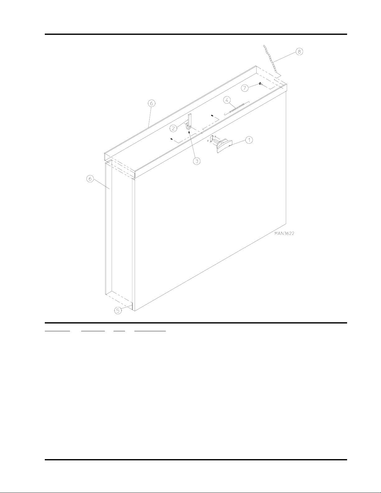
Control Door Assembly
Illus. No. Part No. Qty. Description
1 112366 1 Logo ONLY
2* 881691 1 Control Door Assembly
(includes illus. nos. 2, 3, 7, and 8)
For Models Mfd. as of October 24, 1997
881045 1 Control Door Assembly
(includes illus. nos. 2, 3, 7, and 8)
For Models Mfd. prior to October 24, 1997
3 117600 4 Noise Suppression Tape (sold by the foot)
4 150309 4 #10-16 x 1/2” Hex Head TEK Crimptite Screw
5 102603 1 Control Door Rod Support Catch
6 102601 1 Control Door Rod Retainer Clip
7 102502 1 Control Door Support Rod
8 882541 2 Spring Turn Latch (2-piece)
* Specify color when ordering.
American Dryer Corporation 88 Currant Road / Fall River, MA 02720-4781
Page 5
Phase 6 OPL Microprocessor Control Panel Assembly
3
Illus. No. Part No. Qty. Description
1 112537 1 Phase 6 OPL Keyboard
112276 1 OPL Stick-on Labels
(English Only) ... Not Illustrated
112275 1 OPL Stick-On Labels
(Spanish, Italian, and Hebrew) ... Not Illustrated
112277 1 3 Language OPL Stick-On Labels
(ENGLISH, SPANISH, and HEBREW) ... Not Illustrated
112278 1 5 Language OPL Stick-On Labels
(ITALIAN, Dutch, French, German, and Chinese) ... Not Illustrated
2 881745 1 Phase 6 Microprocessor Controller (computer) Panel ONLY
881747 1 Phase 6 OPL Non-Reversing Computer Panel Assembly Complete
(includes illus. nos. 1 through 5 and 7 through 9)
881746 1 Phase 6 OPL Reversing Computer Panel Assembly Complete
(includes illus. nos. 1 through 5 and 7 through 9)
3 137123 1 Phase 6 OPL Non-Reversing Microprocessor Controller ONLY
137122 1 Phase 6 OPL Reversing Microprocessor Controller ONLY
4 150005 2 #6-32 x 3/4” Phillips Round Head Machine Screw
5 153010 2 #6 Star Washer
6 150309 1 #10-32 x 1/2” Hex Head TEK Crimptite Screw
7 136048 1 1/8-Amp (slo blo) Fuse
8 136017 1 3.15-Amp (fast acting) Fuse
9 136019 1 1-Amp (fast acting) Fuse
Telephone: (508) 678-9000 Fax: (508) 678-9447
Page 6
4
Microprocessor Control Box Assembly
American Dryer Corporation 88 Currant Road / Fall River, MA 02720-4781
Page 7

Microprocessor Control Box Assembly
Illus. No. Part No. Qty. Description
1 881790 1 Burner Control Wiring
2 881789 1 Basket (tumbler) Hi-Limit Temperature Sensor Harness
3 881637 1 Sail Switch Hi-Limit Harness
4 881788 1 Power Control Harness
(for non-reversing gas models Only)
881787 1 Power Control Harness
(for reversing gas models Only)
881786 1 Power Control Harness
(for reversing steam models Only)
5 881785 1 Door Switch Harness
6 824993 1 Rotational Sensor Harness
(front wiring box to rear wiring box)
824994 1 Rotational Sensor Harness
(rear wiring box to sensor)
7 122648 1 4-Pin Connector
8 122706 4 Socket Terminal ONLY
9 122646 1 2-Pin Connector
10 122706 2 Socket Terminal ONLY
11 122706 9 Socket Terminal ONLY
12 122640 1 9-Pin Connector
13 122706 6 Socket Terminal ONLY
14 122644 1 6-Pin Terminal
5
Telephone: (508) 678-9000 Fax: (508) 678-9447
Page 8
6
Front Panel/Main Door Assemblies
For Models Mfd. as of October 24, 199T
American Dryer Corporation 88 Currant Road / Fall River, MA 02720-4781
Page 9

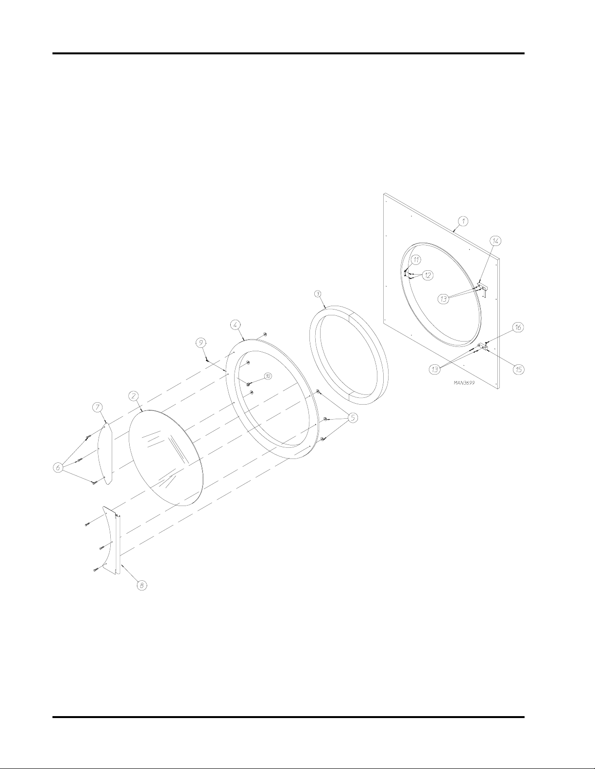
Front Panel/Main Door Assemblies
For Models Mfd. as of October 24, 1997
Illus. No. Part No. Qty. Description
1 881871 1 Front Panel Assembly (white)
(includes illus. nos. 1, 11, and 12)
881697 1 Front Panel Assembly (blue)
(includes illus. nos. 1, 11, and 12)
2 102214 1 29-7/8” Door Glass
170730 1 Door Glass Adhesive (10.3 oz. cartridge)
3 882411 1 Main Door Extruded Gasket (104”)
170730 1 Door Gasket Adhesive (10.3 oz. cartridge)
4 881689 1 White Main Door Assembly Complete
(includes illus. nos. 2 through 10)
881738 1 Blue Main Door Assembly Complete
(includes illus. nos. 2 through 10)
881684 1 White Main Door Ring
881756 1 Blue Main Door Ring
5 881806 6 1/4-20 Free Spin Wash Nut (white)
881807 6 1/4-20 Free Spin Wash Nut (blue)
6 881740 6 1/4-20 x 5/8” (white) Carriage Bolt
881739 6 1/4-20 x 5/8” (blue) Carriage Bolt
7 881688 1 White CRS Main Door Handle
881737 1 Blue CRS Main Door Handle
8 881685 1 White Main Door Hinge
881757 1 Blue Main Door Hinge
9 150120 1 Main Door Latch Screw
10 151012 1 #10-32 White Acorn Nut
151014 1 #10-32 Blue Acorn Nut
11 170330 1 Friction Door Catch
12 154215 2 5/32” Pop Rivet
13 150443 4 1/4-20 x 3/4” Stainless Steel Cap Screw
14 881440 1 White Top Hinge Block
(includes illus. nos. 13 and 14)
881736 1 Blue Top Hinge Block
(includes illus. nos. 13 and 14)
15 881441 1 White Bottom Hinge Block
(includes illus. nos. 13, 15, and 16)
881735 1 Blue Bottom Hinge Block
(includes illus. nos. 13, 15, and 16)
16 153031 1 Nylon Washer
7
Telephone: (508) 678-9000 Fax: (508) 678-9447
Page 10
8
Front Panel/Main Door Assemblies
For Models Mfd. prior to October 24, 1997
Illus. No. Part No. Qty. Description
1 881741 1 White Main Door Handle
881760 1 Blue Main Door Handle
2 151011 3 5/16-18 Acorn Nut
3 881552 1 White Main Door ONLY
881550 1 Blue Main Door ONLY
881816 1 White Main Door Assembly
(includes illus. nos. 1 through 7)
881820 1 Blue Main Door Assembly
(includes illus. nos. 1 through 7)
4 151011 9 5/16-18 Acorn Nut
5 102210 1 20-7/16” Door Glass
170730 1 Door Glass Adhesive (10.3 oz. cartridge)
6 102112 2 Door Magnet (5/16” x 1/4” x 34-3/4”)
7 102356 1 Main Door Gasket (13-1/6” x 1-3/8” x 97-1/2”)
8 881441 1 White Bottom Hinge Block with Stainless Steel Cap Screw
881735 1 Blue Bottom Hinge Block with Stainless Steel Cap Screw
9 150443 4 1/4-20 x 3/4” Stainless Steel Cap Screw
10 881440 1 White Top Hinge Block with Stainless Steel Cap Screw
881736 1 Blue Top Hinge Block with Stainless Steel Cap Screw
11 881799 1 White Front Panel Assembly
881920 1 Blue Front Panel Assembly
American Dryer Corporation 88 Currant Road / Fall River, MA 02720-4781
Page 11
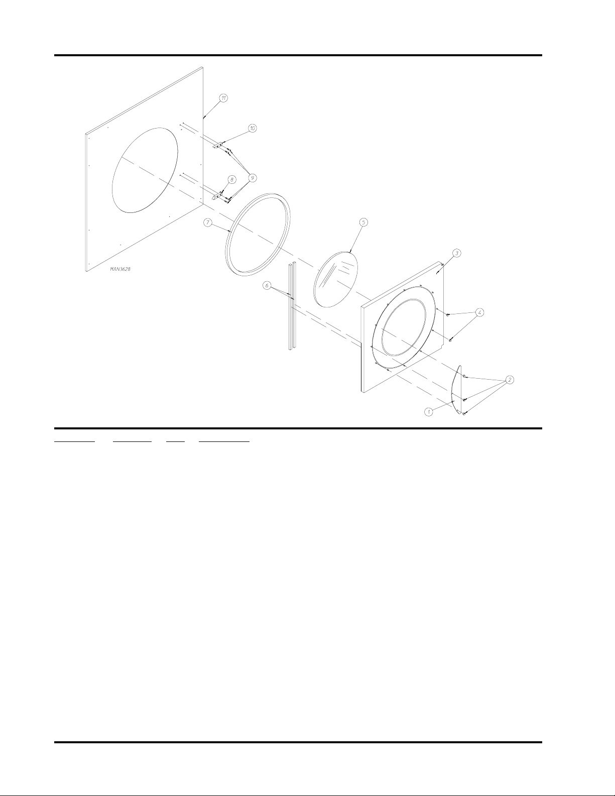
Main Door Switch
For Models Mfd. as of October 24, 1997
9
Illus. No. Part No. Qty. Description
1 150006 2 #6-32 x 7/8” Phillips Pan Head Machine Screw
2 152013 2 #6-32 Hex Nut 1/4” ATF
3 153010 2 #6 Star Washer
4 137005 1 Single Pole Door Switch
5 150443 4 1/4-20 x 3/4” Stainless Steel Cap Screw
6 881687 1 White Main Door Switch Housing ONLY
881695 1 Blue Main Door Switch Housing ONLY
881702 1 White Main Door Switch with Housing Assembly
(includes illus. nos. 1 through 4 and 6)
881700 1 Blue Main Door Switch with Housing Assembly
(includes illus. nos. 1 through 4 and 6)
7 150301 2 #8-18 x 7/16” Phillips Pan Head TEK Screw
8 881441 1 White Bottom Hinge Block
(includes illus. nos. 5, 8, and 10)
881735 1 Blue Bottom Hinge Block
(includes illus. nos. 5, 8, and 10)
9 881440 1 White Top Hinge Block
(includes illus. nos. 5 and 9)
881736 1 Blue Top Hinge Block
(includes illus. nos. 5 and 9)
10 153031 1 Nylon Washer
Telephone: (508) 678-9000 Fax: (508) 678-9447
Page 12
10
Main Door Switch
For Models Mfd. prior to October 24, 1997
Illus. No. Part No. Qty. Description
1 150006 2 #6-32 x 7/8” Phillips Pan Head Machine Screw
2 152013 2 #6-32 Hex Nut 1/4” ATF
3 153010 2 #6 Star Washer
4 137005 1 Single Pole Door Switch
5 150301 2 #8-18 x 7/16” Phillips Pan Head TEK Screw
6 881726 1 White Main Door Switch Housing ONLY
881698 1 White Main Door Switch with Housing Assembly
(includes illus. nos. 1 through 4 and 6)
7 150443 4 1/4-20 x 3/4” Stainless Steel Cap Screw
8 881441 1 White Bottom Hinge Block
(includes illus. nos. 7, 8, and 10)
9 881440 1 White Top Hinge Block
(includes illus. nos. 7 and 9)
10 153031 1 Nylon Washer
American Dryer Corporation 88 Currant Road / Fall River, MA 02720-4781
Page 13
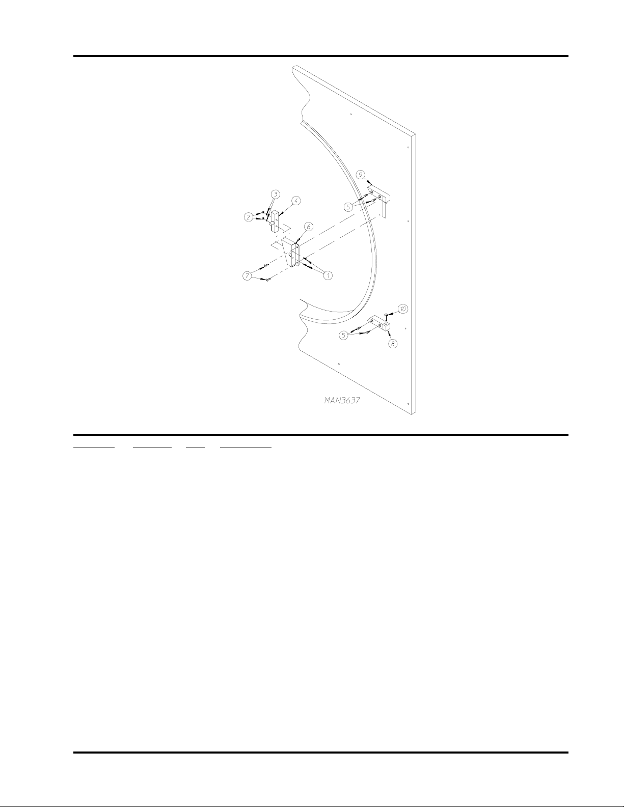
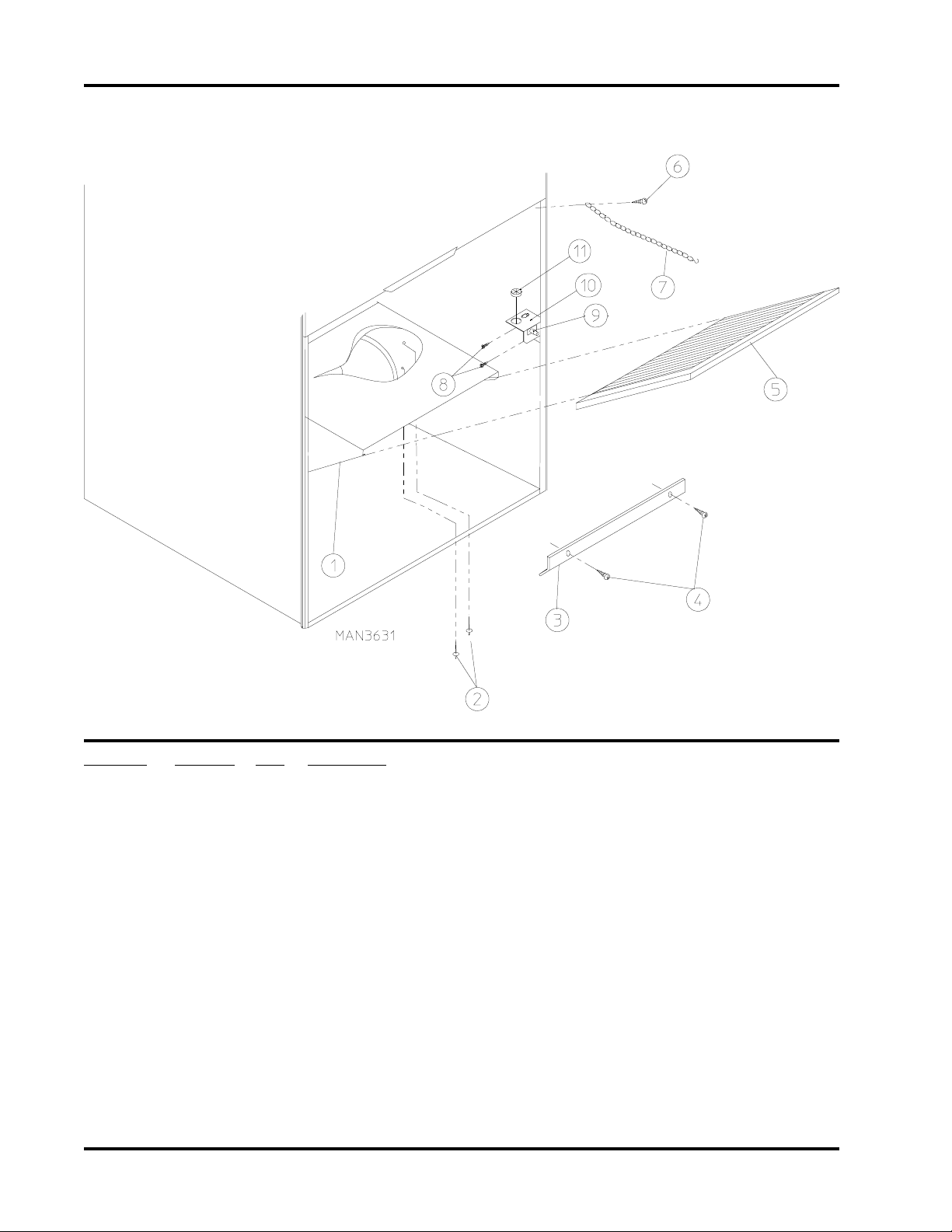
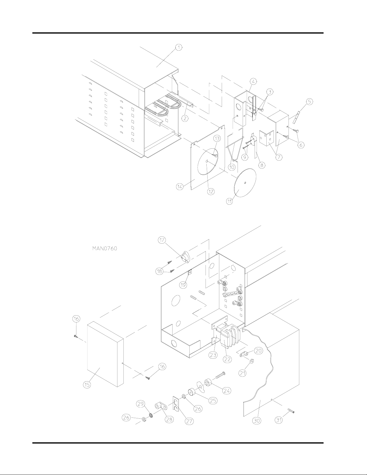
Drop Lint Door Assembly
11
Illus. No. Part No. Qty. Description
1 800150 1 Knob Latch Kit Assembly
(includes illus. nos. 1 through 3)
2 160009 1 Knob Latch Adjustable Cam ONLY
3 150425 1 #12-24 x 3/8” Round Head Machine Screw ONLY
(screw for knob latch adjustable cam)
4 157000 1 Drop Lint Door Spring
5* 881692 1 Insulated Drop Lint Door Assembly
(includes illus. nos. 5 and 6)
6 117600 7 Noise Suppressor Tape (sold by the foot)
7 150419 2 #6 x 1/2” Tamperproof TEK Screw
150418 1 Tamperproof Screw Hand Driver
8 108120 1 Chain for Drop Lint Door (10-1/2” length)
* Specify color when ordering.
Telephone: (508) 678-9000 Fax: (508) 678-9447
Page 14
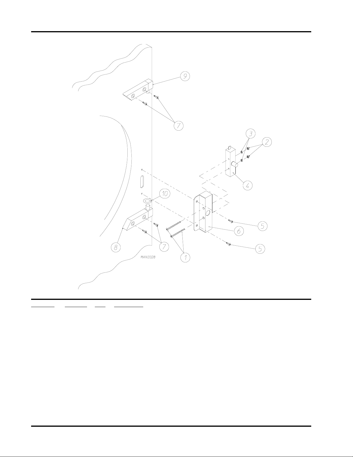
12
Lint Trap Assembly
For Gas and Electric Models with 8” Exhaust
Illus. No. Part No. Qty. Description
1 800420 1 Non-Reversing Lint Trap Assembly Complete
(includes illus. nos. 1, 3, 4, and 5)
800421 1 Non-Reversing Lint Trap ONLY
800422 1 Reversing Lint Trap Assembly Complete
(includes illus. nos. 1, 3, 4, and 5)
800423 1 Reversing Lint Trap ONLY
2 154200 7 5/32” Pop Rivet
3 304101 1 Lint Screen Holder ONLY
4 150300 2 #10-16 x 1/2” Hex Washer TEK PLTD
5 800506 1 Lint Screen ONLY
6 150419 2 #6 x 1/2” Tamperproof TEK Screw
150418 1 Tamperproof Screw Hand Driver
7 108120 1 Chain for Drop Lint Door (10-1/2” length)
8 150425 2 #12-24 x 3/8” Phillips Round Head Screw
9 122116 1 Lint Drawer Switch ONLY
10 323724 1 Lint Drawer Switch Bracket
11 121400 1 Universal Bushing
American Dryer Corporation 88 Currant Road / Fall River, MA 02720-4781
Page 15

Lint Trap Assembly
For Steam Models with 10” Exhaust
13
Illus. No. Part No. Qty. Description
1 800440 1 Non-Reversing Lint Trap Assembly Complete
(includes illus. nos. 1, 3, 4, and 5)
800433 1 Non-Reversing Lint Trap ONLY
800441 1 Reversing Lint Trap Assembly Complete
(includes illus. nos. 1, 3, 4, and 5)
800434 1 Reversing Lint Trap ONLY
2 154200 7 5/32” Pop Rivet
3 304101 1 Lint Screen Holder ONLY
4 150300 2 #10-16 x 1/2” Hex Washer TEK PLTD
5 800506 1 Lint Screen ONLY
6 150419 2 #6 x 1/2” Tamperproof TEK Screw
150418 1 Tamperproof Screw Hand Driver
7 108120 1 Chain for Drop Lint Door (10-1/2” length)
8 150425 2 #12-24 x 3/8” Phillips Round Head Screw
9 122116 1 Lint Drawer Switch ONLY
10 323724 1 Lint Drawer Switch Bracket
11 121400 1 Universal Bushing
Telephone: (508) 678-9000 Fax: (508) 678-9447
Page 16
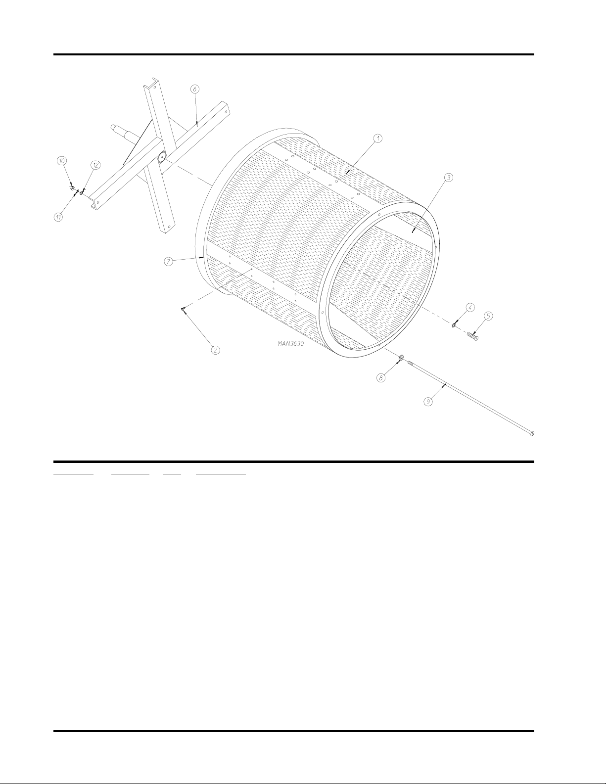
14
Basket (Tumbler)/Support Assemblies
Illus. No. Part No. Qty. Description
1 881780 1 Basket (tumbler) ONLY
881783 1 1-3/4” Non-Reversing Basket (tumbler) and Support Assembly Complete
(includes illus. nos. 1 through 12)
881782 1 1-3/4” Reversing Basket (tumbler) and Support Assembly Complete
(includes illus. nos. 1 through 12)
2 150413 40 #10-16 x 1/2” Torx Crimptite
3 390074 4 Basket (tumbler) Rib ONLY
4 153002 1 5/16” Lock Washer
5 150500 1 5/16-18 x 3/4” Socket Button Head Screw
6 881778 1 1-3/4” Non-Reversing Basket (tumbler) Support ONLY
881779 1 1-3/4” Reversing Basket (tumbler) Support ONLY
7 116000 1 Felt Collar ONLY
401010 1 #847 Adhesive For Felt Collar
8 153004 4 3/8” Flat Washer
9 100905 4 3/8-16 x 37” Tie Rod
10 152005 4 3/8-16 Hex Nut
11 153005 4 3/8” Lock Washer
12 153004 4 3/8” Flat Washer
American Dryer Corporation 88 Currant Road / Fall River, MA 02720-4781
Page 17

Microprocessor Sensor Bracket Assembly
15
Illus. No. Part No. Qty. Description
1 880251 1 1/4” Temperature Sensor Probe Assembly Complete
(includes illus. nos. 1 and 5 through 8)
2 130103 1 225º Large Automatic Thermostat ONLY
3 153010 2 #6 Star Washer
4 152000 2 #6-32 Hex Nut
5 121028 2 Insulated Terminal ONLY
6 122701 4 Socket Terminal ONLY
7 122605 1 4-Pin Socket Connector
8 154007 2 1/4” Tinnerman Push On Fastener
9 150005 2 #6-32 x 1/4” Phillips Round Head Machine Screw
10 801425 1 Microprocessor Sensor Bracket Assembly Complete
(includes illus. nos. 1 through 10)
305007 1 Universal Sensor Bracket ONLY
11 122604 1 4-Pin Connector ONLY
12 122700 4 Pin Terminal ONLY
122801 1 Pin/Socket Extraction Tool
13 150301 2 #8-18 x 7/16” Phillips Pan Head TEK Screw
Telephone: (508) 678-9000 Fax: (508) 678-9447
Page 18

16
Tumbler Bearing Assembly
Illus. No. Part No. Qty. Description
1 880220 1 1-3/4” Flange Bearing with Nylock Setscrew
2 153025 4 9/16” Lock Washer
3 152050 4 9/16-12 Hex Nut
4 150508 2 3/8-16 x 3/4” Hex Head Machine Bolt
5 153005 2 3/8” Lock Washer
6 152005 2 3/8-16 Hex Nut
7 150600 2 3/8-16 x 1-1/2” Hex Head Machine Bolt
8 153004 * 3/8” Flat Washer
9 153005 2 3/8” Lock Washer
10 152005 2 3/8-16 Hex Nut
American Dryer Corporation 88 Currant Road / Fall River, MA 02720-4781
Page 19

Tumbler Bearing Assembly (continued)
Illus. No. Part No. Qty. Description
11 150501 4 5/16-18 x 3/4” Hex Head Machine Bolt
12 153002 4 5/16” Lock Washer
13 153001 4 5/16” Flat Washer
14 150621 2 5/16-18 x 1-1/2” Hex Head Machine Bolt
15 152004 2 5/16-18 Hex Nut
16 801107 1 1-3/8” Bearing Box Magnetic Sensor Assembly Complete
(includes illus. nos. 4 through 20)
For Models Mfd. without Rotational Sensor
(for models mfd. as of April 12, 1999)
801101 1 1-3/8” Bearing Box Assembly Complete
(includes illus. nos. 4 through 20)
For Models Mfd. without Rotational Sensor
(for models mfd. prior to April 12, 1999)
801103 1 1-3/8” Bearing Box and Support ONLY
(includes illus. nos. 4, 5, 6, 16, and 17)
801105 1 1-3/8” Bearing Box ONLY
17 801104 1 Pillow Block Bearing Support ONLY
18 880202 1 1-3/8” Pillow Block Bearing with Nylock Setscrew
880779 1 1-3/8” Pillow Block Bearing Assembly with Magnet
(for models mfd. with optional rotational sensor)
19 152004 2 5/16-18 Hex Nut
20 150610 2 5/16-18 x 1-1/2” Allen Setscrew
21 101100 1 18” Pulley
(for non-reversing models Only)
101118 1 18-3/4” Pulley
(for reversing models Only)
22 101119 1 1-3/8” Taper Lock Hub (key not included)
For Reversing Models ONLY
23 154301 2 5/16-18 x 5/16” Allen Setscrew
(for non-reversing models Only)
24 100713 1 1/4” x 1/4” x 7/8” Key
(for non-reversing models Only)
100735 1 Shaft Key (for taper lock hub)
For Reversing Models ONLY
25 100106 1 5L-690 V-Belt (basket [tumbler] to idler)
26 824807 1 Rotational Sensor Assembly
(for models mfd. with optional rotational sensor)
17
* As required.
Telephone: (508) 678-9000 Fax: (508) 678-9447
Page 20
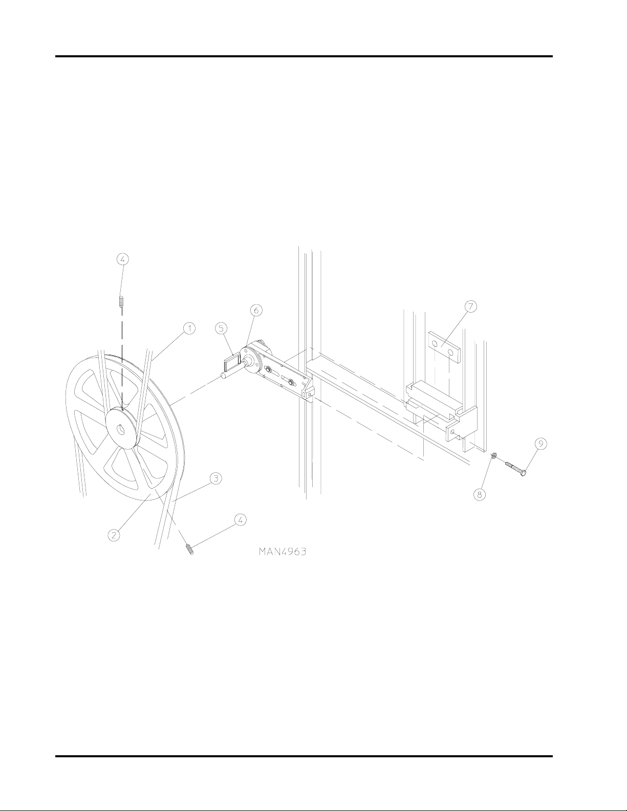
18
Idler Bearing Assembly
American Dryer Corporation 88 Currant Road / Fall River, MA 02720-4781
Page 21

Idler Bearing Assembly
Illus. No. Part No. Qty. Description
1 100106 1 5L-690 V-Belt (basket [tumbler] to idler)
2 101140 1 14” x 3” Compound Pulley
3 100117 1 4L-620 V-Belt (idler to motor)
For Non-Reversing Models ONLY
100114 1 4L-630 V-Belt (idler to motor)
For Reversing Models ONLY
4 154301 2 5/16-18 x 1” Allen Setscrew
5 100705 1 3/16” x 3/16” x 1-3/8” Key
6 882576 1 Idler Bearing Assembly Complete
(includes illus. nos. 5 through 12)
7 801009 1 Idler Square Washer
8 152004 1 5/16-18 Hex Nut
9 150509 1 5/16-18 x 3” Hex Head Machine Bolt
19
Telephone: (508) 678-9000 Fax: (508) 678-9447
Page 22

20
Non-Reversing T.E.F.C. Motor Mount Assembly
Illus. No. Part No. Qty. Description
1 100117 1 4L 620 V-Belt (motor to idler)
2 100701 1 3/16” x 3/16” x 1” Key
3 101133 1 5/8” x 2-1/4” Motor Pulley (60 Hz Only)
101130 1 5/8” x 2-1/2” Motor Pulley (50 Hz Only)
4 150501 4 5/16-18 x 3/4” Hex Head Machine Bolt
5 153002 4 5/16” Lock Washer
6 153001 4 5/16” Flat Washer
7 100073* 1 1 HP 120/208/230v 1ø 60 Hz Totally Enclosed, Fan-Cooled
(T.E.F.C.) Motor with Plug (56Z frame)
181016 1 3/4 HP 230v 1ø 50 Hz Non-Reversing Totally Enclosed, Fan-Cooled
(T.E.F.C.) Motor
8 122701 8 Socket Terminal
122801 1 Pin/Socket Extraction Tool
9 137030 1 8-Pin Housing Connector
824714 1 120 Volt - 1ø Motor Harness
824709 1 240 Volt - 1ø Motor Harness
10 152004 4 5/16-18 Hex Nut
American Dryer Corporation 88 Currant Road / Fall River, MA 02720-4781
Page 23

Non-Reversing T.E.F.C. Motor Mount Assembly (continued)
Illus. No. Part No. Qty. Description
11 153002 4 5/16” Lock Washer
12 153001 4 5/16” Flat Washer
13 117600 4 Noise Suppressor Tape (sold by the foot)
14 154000 4 5/16-18 Tinnerman Nut
15 800919 1 Non-Reversing Motor Mount ONLY (56Z frame)
803992* 1 1 HP 120/230v 1ø 60 Hz Totally Enclosed, Fan-Cooled
(T.E.F.C.) Motor Mount Assembly with Plug Complete
(includes illus. nos. 2 through 7 and 13 through 20)
803953 1 3/4 HP 230v 1ø 50 Hz Non-Reversing Totally Enclosed, Fan-Cooled
(T.E.F.C.) Motor Mount Assembly Complete
(includes illus. nos. 2 through 6 and 13 through 22)
803955* 1 1 HP 230/380/460v 3ø 60 Hz Non-Reversing Totally Enclosed, Fan-Cooled
(T.E.F.C.) Motor Mount Assembly Complete
(includes illus. nos. 2 through 6 and 13 through 22)
803958* 1 1 HP 230/380/460v 3ø 50 Hz Non-Reversing Totally Enclosed, Fan-Cooled
(T.E.F.C.) Motor Mount Assembly Complete
(includes illus. nos. 2 through 6 and 13 through 22)
16 153051 1 3/4” S.A.E. Flat Washer
17 100603 1 16” Impellor with 3/4” Bore
18 100714 1 3/16” x 3/16” x 1-7/8” Key
19 153050 2 1/2” S.A.E. Flat Washer
20 152006 2 1/2-20 Left Hand Jam Nut
21 120200 1 3/8” x 90° Connector
824696 1 3-Phase (3ø) Motor Harness
22* 100075 1 1 HP 208/230/240/460v 3ø 50/60 Hz Totally Enclosed, Fan-Cooled
(T.E.F.C.) Motor
21
* Specify voltage when ordering.
Telephone: (508) 678-9000 Fax: (508) 678-9447
Page 24

22
Reversing T.E.F.C. Motor Mount Assembly
American Dryer Corporation 88 Currant Road / Fall River, MA 02720-4781
Page 25

Reversing T.E.F.C. Motor Mount Assembly
Illus. No. Part No. Qty. Description
1 100114 1 4L-630 V-Belt (motor to idler)
2 100701 1 3/16” x 3/16” x 1” Key
3 101130 1 5/8” x 2-1/2” Motor Pulley (60 Hz Only)
101139 1 5/8” x 2-3/4” Motor Pulley (50 Hz Only)
4 120200 1 3/8” x 90° Connector
824697 1 3-Phase (3ø) Drive Motor Harness
5* 181003 1 1/2 HP 208/230/380/460v 3ø 50/60 Hz Totally Enclosed, Fan-Cooled
(T.E.F.C.) 56Z Frame
6 150501 4 5/16-18 x 3/4” Hex Head Machine Bolt
7 153002 4 5/16” Lock Washer
8 153001 4 5/16” Flat Washer
9* 100075 1 1 HP 220/230/380/460v 3ø 50/60 Hz Totally Enclosed, Fan-Cooled
(T.E.F.C.) Motor
with 3/4” Shaft (56Z frame)
10 120200 1 3/8” x 90° Connector
824698 1 3-Phase (3ø) Blower (fan/impellor) Motor Harness
11 150501 4 5/16-18 x 3/4” Hex Head Machine Bolt
12 153002 4 5/16” Lock Washer
13 153001 4 5/16” Flat Washer
14 154000 8 5/16” Tinnerman Nut
15 152004 7 5/16” Hex Nut
16 153002 4 5/16” Lock Washer
17 153001 4 5/16” Flat Washer
18 800912 1 Reversing Motor Mount ONLY (56Z frame)
803952* 1 Reversing Totally Enclosed, Fan-Cooled
(T.E.F.C.) Motor Mount Assembly Complete
(includes illus. nos. 2 through 14 and 18 through 24)
For 60 Hz Models ONLY
803987* 1 Reversing T.E.F.C. Motor Mount Assembly Complete
(includes illus. nos. 2 through 14 and 18 through 24)
For 50 Hz Models ONLY
19 117600 4 Noise Suppressor Tape (sold by the foot)
20 153050 1 1/2” S.A.E. Flat Washer
21 100702 1 1/8” x 1/8” x 1-1/2” Key
22 100603 1 16” Impellor with 3/4” Bore
23 153050 ** 1/2” S.A.E. Flat Washer
24 152006 2 1/2-20 Left Hand Jam Nut
23
* Specify voltage when ordering.
** As required.
Telephone: (508) 678-9000 Fax: (508) 678-9447
Page 26
24
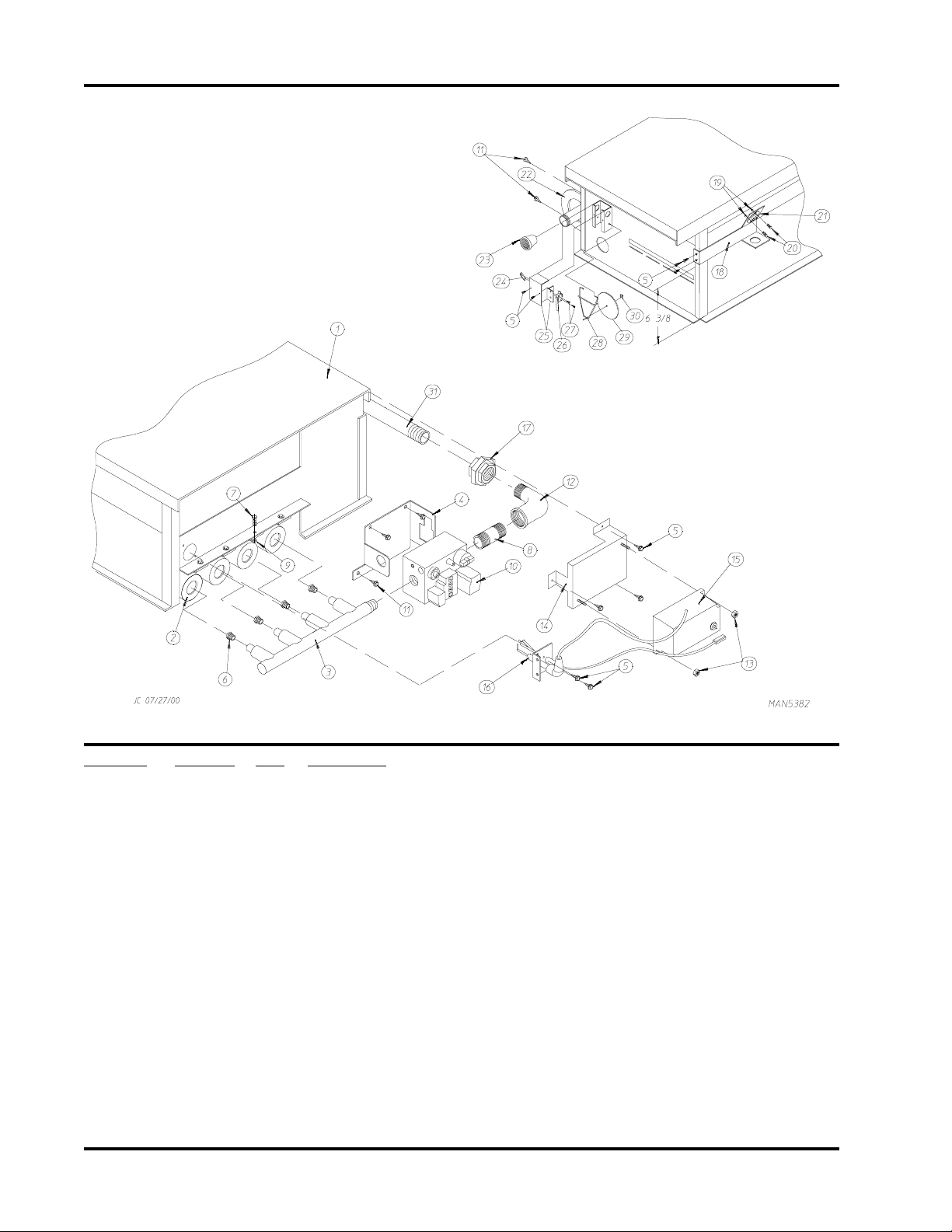
Direct Spark Ignition (DSI) Burner Assembly
Illus. No. Part No. Qty. Description
1* 809716 1 Natural Gas Burner Assembly Complete
(includes illus. nos. 1 through 32
For Models Manufactured Natural Gas ONLY
809717 1 Liquid Propane (L.P.) Gas Burner Assembly Complete
(includes illus. nos. 1 through 32)
For Models Manufactured with Liquid Propane (L.P.) Gas ONLY
810047 1 Burner Box ONLY
881231* 1 Burner Liquid Propane (L.P.) Conversion Kit
2 141105 4 Large Burner Tube
3 141210 1 3/4” Direct Spark Ignition (DSI) Manifold (4-port)
4 318714 1 Bracket For Horizontal Facing Gas Valve
5 150300 9 #10-16 1/2” Hex Washer TEK PLTD
6* 140820 4 #29 Burner Orifice (natural gas) ONLY
140805 4 #47 Burner Orifice (liquid propane [L.P.] gas Only)
7 150108 4 #8-32 x 1/2” Phillips Round Head Machine Screw
8 142707 4 1/2” x 1 1/2” Long Black Nipple
9 151001 4 #8-32 Pal Nut
American Dryer Corporation 88 Currant Road / Fall River, MA 02720-4781
Page 27

Direct Spark Ignition (DSI) Burner Assembly (continued)
Illus. No. Part No. Qty. Description
10 128927 1 1/2” 24 VAC Redundant (natural gas) Gas Valve
880960 1 1/2” 24 VAC Direct Spark Ignition (DSI)
Liquid Propane (L.P.) Gas Valve Assembly
11 150309 5 #10-16 x 1/2” Hex Head TEK Crimptite Screw
12 142506 1 1/2” Street Elbow
13 152013 2 #6-32 Hex Nut 1/4” ATF
14 810030 1 Johnson Controls Direct Spark Ignition (DSI) Module Mounting Bracket
15 128935 1 Direct Spark Ignition (DSI) Module with 3 Tries
16 809309 1 Ignitor Probe Assembly with 19” Leads
17 142600 1 1/2” Black Union
18 319704 1 HI-Limit Mounting Bracket
19 151000 2 #6-32 Pal Nut
20 150001 2 #6-32 x 1/2” Phillips Round Head Machine Screw
21 130201 1 330° HI-Limit Manual Reset
22 318700 1 Pipe Bracket (bent)
23 143000 1 3/4” to 1/2” Reducing Coupling
142936 1 3/4” BSPT x 1/2” N.P.T. Coupling (CE Only)
24 154004 1 Twin Speed Nut
25 802799 1 Sail Switch Box Cover and Bracket ONLY
(refer to Sail Switch Assembly on
26 122200 1 Sail Switch ONLY
27 150303 2 #4 x 3/4” Pan Head “A” Machine Screw
28 105500 1 Sail Switch Actuator Rod
29 319202 1 Sail Switch Damper (flat)
30 154002 1 1/8” Push On Fastener
31 142809 1 1/2” x 29-1/8” Nipple
page 38)
25
* Consult factory for elevations over 2,000 feet.
Telephone: (508) 678-9000 Fax: (508) 678-9447
Page 28

26
Hot Surface Ignition (HSI) Burner Assembly
Illus. No. Part No. Qty. Description
1 881781* 1 Natural Gas Burner Assembly Complete Less Orifices
(includes illus. nos 1 through 9 and 11 through 31)
For Models Manufactured with Natural Gas ONLY
881784* 1 Liquid Propane (L.P.) Gas Burner Assembly Complete Less Orifices
(includes illus. nos 1 through 9 and 11 through 31)
For Models Manufactured with Liquid Propane (L.P.) Gas ONLY
810045 1 Burner Box ONLY
(for models mfd. as of October 5, 1998)
802237 1 Burner Box ONLY
(for models mfd. prior to October 5, 1998)
881231** 1 MLG-75 Burner Liquid Propane (L.P.) Conversion Kit
American Dryer Corporation 88 Currant Road / Fall River, MA 02720-4781
Page 29

Hot Surface Ignition (HSI) Burner Assembly
Illus. No. Part No. Qty. Description
2 323013 1 Burner Box Shield/Front ONLY
(for models mfd. as of October 5, 1998)
318041 1 Burner Box Front ONLY
(for models mfd. prior to October 5, 1998)
3 150309 5 #10-16 x 1/2” Hex Head TEK Crimptite Screw
4 810029 1 Hot Surface Ignition (HSI) Module Mounting Bracket
5 881797 1 Hot Surface Ignition (HSI) Module II
6 141105 4 Large Burner Tube
7 150103 4 #8-32 x 3/4” Phillips Round Head Machine Screw
8 153000 4 #8 Steel Burr
9 151001 4 #8-32 Pal Nut
10** 140820 4 #29 Burner Orifice (natural gas) ONLY
140805 4 #47 Burner Orifice (liquid propane [L.P.] gas) ONLY
11 141210 1 4-Port Manifold
12 318700 2 Pipe Bracket (bent)
13 150300 2 #10-16 x 1/2” Hex Washer TEK PLTD
14 128927 1 1/2” 24 VAC Redundant (natural gas) Gas Valve
880960 1 1/2” 24 VAC Liquid Propane (L.P.) Gas Valve Assembly
140411 1 24 VAC Gas Valve Liquid Propane (L.P.) Conversion Kit
15 881367 1 1/2’ Union Shutoff with Tail Piece
16 142809 1 1/2” x 29-1/8” Nipple
17 323737 1 Pipe Bracket
18 319704 1 Hi-Limit Mounting Bracket
19 151000 2 #6-32 Pal Nut
20 150001 2 #6-32 x 1/2” Phillips Round Head Machine Screw
21 130401 1 330º Hi-Limit ONLY
22 --------- 1 Sail Switch
(refer to Sail Switch Assembly on
23 143000 1 3/4” to 1/2” Reducing Coupling
142936 1 3/4” BSPT x 1/2” N.P.T. Coupling (CE Only)
24 150309 2 #10-16 x 1/2” Hex Head TEK Crimptite Screw
25 150309 2 #10-16 x 1/2” Hex Head TEK Crimptite Screw
26 151001 2 #8-32 Pal Nut
27 150309 3 #10-16 x 1/2” Hex Head TEK Crimptite Screw
28 128921 1 Hot Surface Ignition (HSI) Flame Sensor
29 150301 1 #8-18 x 7/16” Phillips Pan Head TEK Screw
30 881597 1 Hot Surface Ignitor (2-1/2” length) - 24 VAC
31 150309 1 #10-16 x 1/2” Hex Head TEK Crimptite Screw
page 38)
27
* Burner orifices are not included and must be ordered separately.
** Consult factory for elevations over 2,000 feet.
Telephone: (508) 678-9000 Fax: (508) 678-9447
Page 30
28
Electric Oven Assembly
ELECTRIC OVEN (FRONT VIEW)
ELECTRIC OVEN (REAR VIEW)
American Dryer Corporation 88 Currant Road / Fall River, MA 02720-4781
Page 31

Electric Oven Assembly
Illus. No. Part No. Qty. Description
1 803005 1 Large Electric Oven Box ONLY
---------* 1 Electric Oven Assembly Complete
2 ---------* - Electric Element
3 150300 2 #10-16 x 1/2” Hex Washer TEK PLTD
4 802800 1 Sail Switch Box with Bracket and Cover ONLY
802801 1 Sail Switch Box Assembly Complete
(includes illus. nos. 4 through 12)
5 154004 1 Twin Speed Nut
6 150309 2 #10-16 x 1/2” Hex Head TEK Crimptite Screw
7 802799 1 Sail Switch Box Cover and Bracket ONLY
(refer to Sail Switch Assembly on
8 122200 1 Sail Switch ONLY
9 150303 2 #4 x 3/4” Pan Head “A” Machine Screw
10 105500 1 Sail Switch Actuator Rod
11 319202 1 Sail Switch Damper (flat)
12 154002 1 1/8” Push On Fastener
13 150300 2 #10-16 x 1/2” Hex Washer TEK PLTD
14 803100 1 Electric Oven Front Cover ONLY
15 320611 1 Large Relay Box Cover ONLY
16 150402 2 #10-24 x 5/8” Slotted Truss Head Machine Screw
17 130400 1 290° Hi-Limit
18 150300 2 #10-16 x 1/2” Hex Washer TEK PLTD
19 154001 2 #10-24 Speed Nut
20 121012 1 Terminal Lug for 110-8 Wire
21 152014 3 1/4-20 Free Spin Wash Nut
22 ---------* 1 Oven Relay
23 ---------* 1 Oven Relay Replacement Coil
24 120081 - Internal Ceramic Insulator (2 per element)
25 120080 - External Ceramic Insulator (2 per element)
26 152008 - #10-32 Hex Nut (4 per element)
27 121011* - Bus Bar
28 ---------* - Terminal Lug
29 153009 - #10 Star Washer (2 per element)
30 320607 1 Large Electric Oven Right Side Cover ONLY
31 150402 2 #10-24 x 5/8” Truss Head Machine Screw
page 38
29
* Refer to Electric Oven Component Application Chart on page 41.
Telephone: (508) 678-9000 Fax: (508) 678-9447
Page 32

American Dryer Corporation 88 Currant Road / Fall River, MA 02720-4781
30
Air Operated Steam Damper Assembly
Page 33

Air Operated Steam Damper Assembly
Illus. No. Part No. Qty. Description
1 165009 1 Steam Coil Assembly
2 153002 6 5/16” Lock Washer
3 152004 6 5/16-18 Hex Nut
4 152002 4 1/4-20 Hex Nut
5 153007 4 1/4” Lock Washer
6 820321 2 Steam Damper Hinge Assembly
7 803415 1 Steam Damper Assembly
(includes illus. nos. 7, 10, and 11)
8 153007 4 1/4” Lock Washer
9 152002 4 1/4-20 Hex Nut
10 115995 108 Steam Damper Gasket (sold by the inch)
11 102350 1 Steam Damper Foam (68-1/2” length)
12 151007 1 7/16-20 Stainless Steel Acorn Nut
13 152007 1 7/16-20 Hex Nut
14 100497 1 1-1/4” Bore x 3” Stroke Piston
15 100492 1 Piston Support Bracket
16 152002 4 1/4-20 Hex Nut
17 153007 4 1/4” Lock Washer
18 100472 1 1/4” x 1/8” Connector
19 143110 1 1/4” Tubing (sold by the foot)
20 100472 1 1/4” x 1/8” Connector
21 100496 1 1/8” Needle Valve
22 143238 1 1/8” Close Nipple
23 100498 1 3-Way Micro Valve - 24 VAC
24 150002 2 #6-32 x 1” Slotted Machine Screw
25 153010 2 #6 Star Washer
26 152000 2 #6-32 Hex Nut
27 330987 1 Micro Valve Support Bracket
28 152002 2 1/4-20 Hex Nut
29 153007 2 1/4” Lock Washer
30 100520 1 1/8” N.P.T. Silencer (muffler)
31
Telephone: (508) 678-9000 Fax: (508) 678-9447
Page 34
American Dryer Corporation 88 Currant Road / Fall River, MA 02720-4781
32
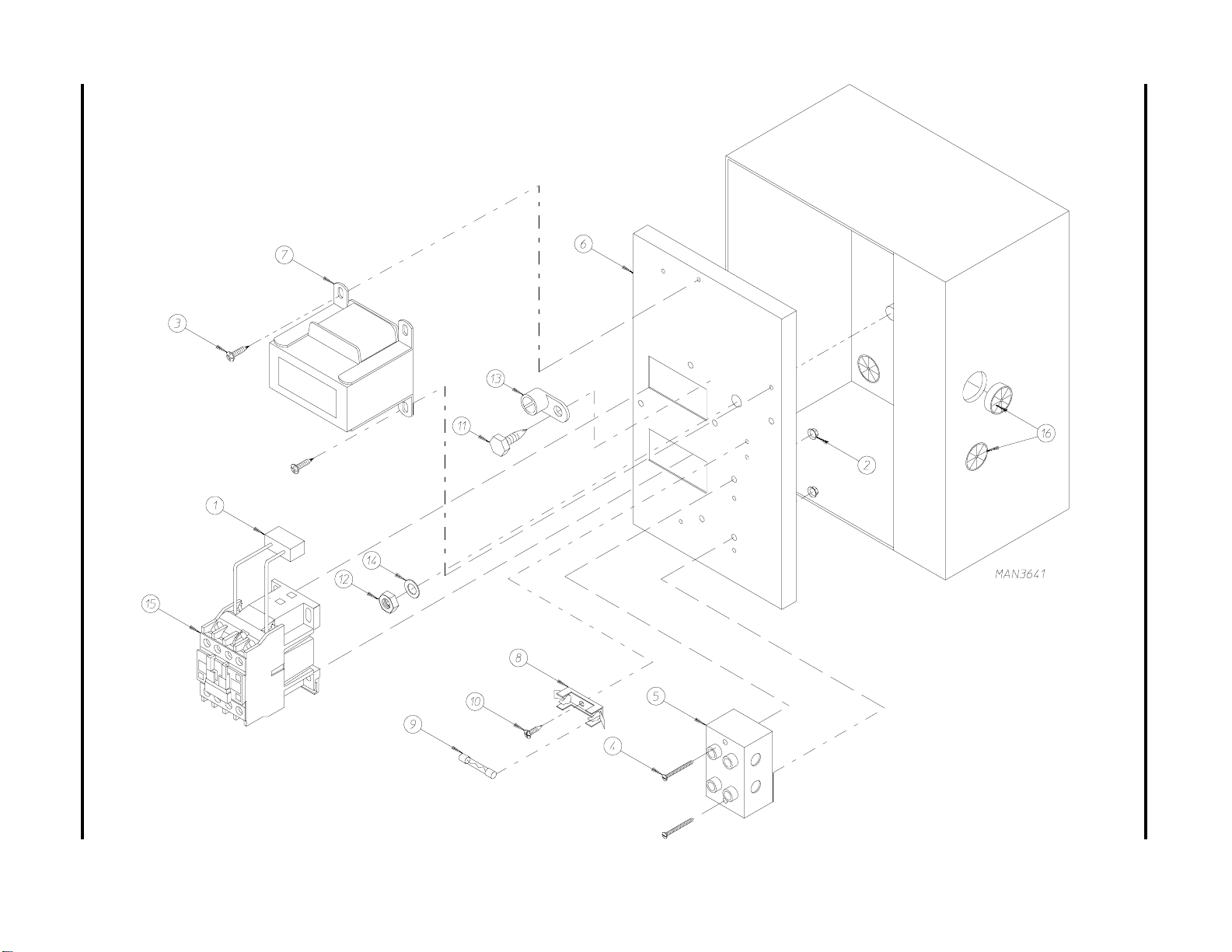
Single-Phase (1ø) Motor, Electric Relay Panel Assembly
Page 35

Single-Phase (1ø) Motor, Electric Relay Panel Assembly
Illus. No. Part No. Qty. Description
1 137015 1 RC Network
2 151000 2 #6-32 Pal Nut
3 150300 2 #10-16 x 1/2” Hex Washer TEK PLTD
4 150008 2 #6-32 x 1-1/4” Phillips Round Head Machine Screw
5 120716 1 2-Position Terminal Block
6 306304 1 Electric Relay Panel Mounting Plate ONLY
881751 1 120 Volt - 1ø Electric Relay Panel Assembly Complete
(includes illus. nos. 1 through 11, 13, and 15)
For Use On Gas Models ONLY
881754 1 208/240 Volt - 1ø Electric Relay Panel Assembly Complete
(includes illus. nos. 1 through 11, 13, and 15)
For Use On Gas Models ONLY
7 --------- 1 Step Down Transformer
(refer Step Down Transformer Usage Listing on page 42)
8 136008 * Fuse Holder ONLY
9 136049 1 3/4-Amp (slo blo) Fuse
(for 120 volt models Only)
136057 2 1/2-Amp (slo blo) Fuse
(for 208/240 volt models Only)
10 150301 * #8-18 x 7/16” Phillips Pan Head TEK Screw
11 150247 1 #10 x 1/2” Hex Washer TEK Screw - Green
12 152004 1 5/16-18 Hex Nut
13 121010 1 L-70 Ground Lug
14 153002 1 5/16” Lock Washer
15 132445 1 3-Pole Contactor - 24 VAC
16 121300 3 Open/Closed Bushing
33
* As required.
Telephone: (508) 678-9000 Fax: (508) 678-9447
Page 36

American Dryer Corporation 88 Currant Road / Fall River, MA 02720-4781
34
3-Phase (3ø) Motor, Non-Reversing Electric Relay Panel Assembly
Page 37

3-Phase (3ø) Motor, Non-Reversing Electric Relay Panel Assembly
Illus. No. Part No. Qty. Description
1 137015 1 RC Network
2 151000 2 #6-32 Pal Nut
3 150300 2 #10-16 x 1/2” Hex Washer TEK PLTD
4 150008 2 #6-32 x 1-1/4” Phillips Round Head Machine Screw
5 120701 1 4-Position Terminal Block
6 322812 1 Electric Relay Panel Mounting Plate ONLY
881800 1 208/240 Volt - 3ø Non-Reversing Electric Relay Panel Assembly Complete
(includes illus. nos. 1 through 11, 13, and 15)
For Use On Gas Models ONLY
7 --------- 1 Step Down Transformer
(refer Step Down Transformer Usage Listing on page 42)
8 136008 2 Fuse Holder ONLY
9 136057 2 1/2-Amp (slo blo) Fuse
10 150301 2 #8-18 x 7/16” Phillips Pan Head TEK Screw
11 150297 1 #10 x 1/2” Hex Washer TEK Screw - Green
12 152004 1 5/16-18 Hex Nut
13 121010 1 L-70 Ground Lug
14 153002 1 5/16” Lock Washer
15 132447 1 3-Pole Contactor - 24 VAC
16 121300 3 Open/Closed Bushing
35
Telephone: (508) 678-9000 Fax: (508) 678-9447
Page 38

American Dryer Corporation 88 Currant Road / Fall River, MA 02720-4781
36
3-Phase (3ø) Motor, Reversing Electric Relay Panel Assembly
Page 39

3-Phase (3ø) Motor, Reversing Electric Relay Panel Assembly
Illus. No. Part No. Qty. Description
1 137060 1 Arc Suppressor (A.S.) Board
2 137013 4 Nylon Standoff
3 150300 2 #10-16 x 1/2” Hex Washer TEK PLTD
4 150008 2 #6-32 x 1-1/4” Phillips Round Head Machine Screw
5 120701 1 4-Position Terminal Block
6 132448 1 Reversing Contactor (208/230/240/380/460 volt) 24 VAC
7 --------- 1 Step Down Transformer
(refer Step Down Transformer Usage Listing on page 42)
8 136008 2 Fuse Holder ONLY (for 208-230/240 Volt models Only)
9 136057 2 1/2-Amp (slo blo) Fuse (for 208-230/240 Volt models Only)
10 150301 2 #8-18 x 7/16” Phillips Pan Head TEK Screw
11 150297 1 #10 x 1/2” Hex Washer TEK Screw - Green
12 152004 1 5/16-18 Hex Nut
13 121010 1 L-70 Ground Lug
14 153002 1 5/16” Lock Washer
15 132447 1 3-Pole Contactor - 24 VAC
16 322812 1 Electric Relay Panel Mounting Plate ONLY
881764 1 208-230/240 Volt Reversing Electric Relay Panel Assembly Complete
(includes illus. nos. 1 through 11, 13 through 17)
For Use On Gas Models ONLY
881766 1 380/416 Volt Reversing Electric Relay Panel Assembly Complete
(includes illus. nos. 1 through 11, 13 through 17)
For Use On Gas Models ONLY
881719 1 460 Volt Reversing Electric Relay Panel Assembly Complete
(includes illus. nos. 1 through 11, 13 through 17, 19, 20, and 21)
For Use On Gas Models ONLY
881755 1 208-230/240 Volt Reversing Electric Relay Panel Assembly Complete
(includes illus. nos. 1 through 11, 13 through 17)
For Use On Steam Models ONLY
881765 1 380/416 Volt Reversing Electric Relay Panel Assembly Complete
(includes illus. nos. 1 through 11, 13 through 17)
For Use On Steam Models ONLY
17 151000 2 #6-32 Pal Nut
18 121300 3 Open/Closed Bushing
19 135501 1 1-Amp Double Pole Circuit Breaker (for 460/480 volt models Only)
20 120768 2 Din Mounting Rail (sold by the inch)
For 460/480 Volt Models ONLY
21 150300 2 #10-16 x 1/2” Hex Washer TEK PLTD
For 460/480 Volt Models ONLY
37
Telephone: (508) 678-9000 Fax: (508) 678-9447
Page 40

38
Sail Switch Assembly
Illus. No. Part No. Qty. Description
1 319203 1 Sail Switch Mounting Bracket
2 319202 1 Sail Switch Damper (flat)
3 319201 1 Sail Switch Box Cover
4 319200 1 Sail Switch Box
5 154004 1 Twin Speed Nut
6 154002 1 1/8" Push On Fastener
7 150309 4 #10-16 x 1/2" Hex Head TEK Crimptite Screw
8 150303 2 #4 x 3/4" Pan Head "A" Machine Screw
9 122200 1 Sail Switch ONLY
881706 1 Sail Switch Box Assembly Complete
(includes illus. nos. 1 through 10)
10 105500 1 Sail Switch Actuator Rod
American Dryer Corporation 88 Currant Road / Fall River, MA 02720-4781
Page 41

Back Guard Assemblies
For Gas and Electric Models ONLY
39
Illus. No. Part No. Qty. Description
1 314514 1 Bottom Back Guard
2 150301 12 #8-18 x 7/16” Phillips Pan Head TEK Screw
3 322809 1 Rear Electrical Box Cover
4 150301 4 #8-18 x 7/16” Phillips Pan Head TEK Screw
5 103500 4 Leveling Leg
6 150301 7 #8-18 x 7/16” Phillips Pan Head TEK Screw
7 150300 12 #10-16 x 1/2” Hex Washer TEK PLTD
8 323738 1 Top Back Guard
9 312527 1 Outer Top
Telephone: (508) 678-9000 Fax: (508) 678-9447
Page 42

40
Back Guard Assembly
For Steam Models ONLY
Illus. No. Part No. Qty. Description
1 314511 1 Bottom Back Guard
2 150300 2 #10-16 x 1/2” Hex Washer TEK PLTD
150301 8 #8-18 x 7/16” Phillips Pan Head TEK Screw
3 322809 1 Rear Electrical Box Cover
4 150301 4 #8-18 x 7/16” Phillips Pan Head TEK Screw
5 103500 4 Leveling Leg
American Dryer Corporation 88 Currant Road / Fall River, MA 02720-4781
Page 43

Telephone: (508) 678-9000 Fax: (508) 678-9447
Electric Oven Component Application Chart
MLE-75
stnemelEeriWnevOguLlanimreT
wKtloVesahPeriW
04614ø34ro322842866.672002146#0023319 010121136APD963131A/N
63802ø34ro31294286651002142#2033314 2101211JAEG583131683131
63032ø33 6204286641002142#2033319 2101211JAEG583131683131
63614ø34ro31294286651002144#0033314 210121134APD753131A/N
63084/064ø34ro30294286641002142#2033319 210121134APD753131A/N
33083ø34ro31294286651002142#2033314 210121134APD753131A/N
03802ø34ro38194286521002164#00333132101211JAEF573131683131
03032ø33 5394286531002134#0033314 210121136APD963131A/N
03614ø34ro37494286521002148#0013316 010121234APD753131A/N
03084/064ø34ro33594286531002148#0013316 0101212JAEB753131A/N
52083ø34ro30494286521002148#0013316 0101212JAEB053131653131
42802ø34ro36194286401002134#0033314 210121136APD963131A/N
42032ø33 3394286411002136#0023313 0101211JAED563131173131
42614ø34ro36494286401002148#0013316 0101212JAEB053131653131
42084/064ø34ro325942864110021401#0003316 0101212JAEB053131653131
02802ø12 4094285401002124#0033312 0101212JAEG583131683131
02032ø12 6294285411002124#0033313 0101212JAEF573131683131
02083ø34ro393942864010021401#0003316 0101212JAEB053131653131
*ylbmessAnevO
.oNtraP
.ytQeziS.oNtraP.ytQeziS.oNtraP.ytQ.oNtraP.oN.taC.oNtraP
raBsuB
1110121N/P
yaleRnevO
lioCyaleR
.oNtraP
* Oven assembly complete does not include oven relay. This item must be ordered separately. When ordering Oven Assembly Complete, specify
3 wire or 4 wire when applicable, as well as if dryer has Microprocessor or non-Microprocessor controls.
N/A = Not Available.
41
Page 44

42
S
TEP
D
OW N
Step Down Transformer Usage Listing
T
RANSFORM ER
U
SAGE
L
ISTING
W
IRE
V
OLTAGE
S
ERVICE
120/208/240 2 132070 132083
208-240 3 or 4 132082 132082
380 3 132082 132082
380 4 132082 132082
416 3 132082 132082
416 4 132067 ---------
460/480 3 132067 ---------
460/480 4 132070 ---------
ADC P
AS
G
ART NO
S
TEA M
.
NOTE: Each transformer requires one (1) Transformer Termination Kit (ADC Part No. 881763).
American Dryer Corporation 88 Currant Road / Fall River, MA 02720-4781
Page 45

Additional Parts Available
Part No. Description
112039 “Black/White/Green Ground” Label
112280 “Clean Lint Screen” Label
112284 “Phase 6 OPL Program Location Summary” Label
114001 “CAUTION-Exhaust/Lint Screen” Label
114006 “WARNING - Fire Hazards” Label
120100 3/8” Straight (BX) Connector
120300 3/8” x 45° (BX) Connector
120400 3/8” Red Jacket (BX) Insulator
120500 3/8” Jiffy Clip (BX) Retainer Clip
120600 3/8” Greenfield (BX)
120800 1/4” In-Line Connector
120802 Red Butt Connector
120902 #74B Wire Nut
120903 Crimp-On Wire Nut
121014 1/4” Insulated (female) Terminal
121499 5-1/2” Harness Tie
121500 7” Harness Tie
121503 Harness Tie Mounting Clip
122804 Manometer (hydro gauge) For Measuring Gas Pressure
404502 White Brush-In-Cap Bottle Touch-Up Paint
404507 Cornflower Blue Brush-In-Cap Bottle Touch-Up Paint
880884 Basket (tumbler) Bearing Puller
43
Telephone: (508) 678-9000 Fax: (508) 678-9447
Page 46

ADC 450173 1 - 01/26/98-50 2* 02/25/98-50 3*05/09/00-50
4*09/11/00-25 5*03/22/01-25 6*05/23/01-25
 Loading...