

Page 1
MEGABIT MODEM 310F AND
320F USER MANUAL
Catalog Number
MMD4067I2 Issue 2
Page 2

Copyright
June 11, 2002
©2002 ADC DSL Systems, Inc. All rights reserved.
Information contained in this document is comp any private to ADC DSL Systems, Inc., and shall not be
modified, used, copied, reproduced or disclosed in whole or in part without written consent of ADC.
Trademark Information
ADC is a registered trademark of ADC Tel ecommunications, Inc.
Megabit Modem is a regist ered trademark of DSL Systems, Inc. No right, license, or interest to such
trademarks is granted hereunder, and you agree that no such right, license, or interest shall be asserted
by you with respect to such trademark.
Other product names ment ioned in this manual are used for identification purposes only and may be
trademarks or registered trademarks of their respective companies.
Disclaimer of Liability
Contents herein are current as of the date of publication. ADC reserves th e right to change the contents
without prior notice. In no event shall ADC be liable for any damages resultin g fro m loss of data , loss of
use, or loss of profits, and ADC further disclaims any and all liability for indirect, incidental, special,
consequential or other similar damages. This disclaimer of liability applies to all products, publications
and services during and after the warra nty period.
Specific Disclaimer for High-risk Activities
This product is not designed or intended for use in high-risk activities, including, without restricting the
generality of the foregoing, on-line control of aircraft, air traffic, aircraft navigation or aircraft
communications; or in the design, construction, operation or maintenance of any nuclear facility. ADC
(including its affiliates) and its suppliers specifically disclaim any express or implied warranty of fitness
for such purposes or any other purposes.
ii Megabit Modem 310F and 320F User Manual
Page 3

About This M anual
ABOUT THIS MANUAL
This manual is intended to help a network administrator install and configure the ADC®
Megabit Modem 310F and 320F for use in a private network environment. It includes:
• a summary of the modem features and suggested applications
• instructions for installing and configuring th e modem s
• explanation of the performance monitoring screens
• technical specifications and cabling pinouts
• a glossary
DOCUMENT CONVENTIONS
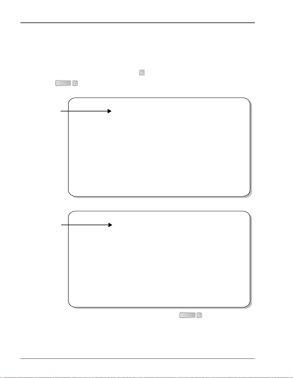
Two types of messages, identified by icons, are used throughout the document:
Notes contain information about special circumstances.
Cautions indicate the possibility of equipment damage or the possibility of
personal injury.
PRODUCT CERTIFICATIONS
FCC
Megabit Modem
This equipment has been tested and f ound to comply with the limits for a Class B digital device,
pursuant to Part 15 of the FCC Rules. These limits are designed to provide reasonable protection
against harmful interference when the equipment is operated in a commercial environmen t. This
equipment generates, uses, and can radiate radio frequency energy and, if not installed and used
in accordance with this instruction manual, may cause harmful interference to radio
communication.
Megabit Modem 310F and 320F User Man ual iii
Page 4

Product Cer tifications
However, there is no guarantee that interference will not occur in a particular installation. If this
equipment does cause harmful interference to radio or television reception, which can be
determined by turning the equipment off and on, the user is encouraged to try to correct the
interference by one or more of the following measures:
• Reorient or relocate the receiving antenna.
• Increase the separation between the equipment and receiver.
• Connect the equipment into an outlet on a circuit different from that to which the receiver
is connected.
• Consult the dealer or an experienced radio/TV technician for help.
cUL
This product meets all safety requirements per UL-1950 standard.
iv Megabit Modem 310F and 320F User Manual
Page 5

Table of Contents
TABLE OF CONTENTS
Chapter 1: Megabit Modem 310F and 320F Features and Applications...........................1
Features................................................................................................................................1
Applications.........................................................................................................................2
Chapter 2: Installing the Megabit Modem 310F and 320F..................................................3
Unpacking and Inspecting the Shipment.............................................................................3
Attaching the Feet................................................................................................................4
Identifying The Connectors.................................................................................................5
Installing the Cabling ..........................................................................................................6
Identifying LEDs.................................................................................................................7
Powering Up and Checking LEDs ......................................................................................8
Chapter 3: Preparing for Configuration and Management................................................9
Connecting a Terminal........................................................................................................9
Configuring the Terminal..................................................................................................10
Logging On and Navigating the Interface.........................................................................10
Logging On to the Local Modem........................................................................10
Logging On to the Remote Modem ....................................................................12
Navigating the Interface......................................................................................13
Logging Off.......................................................................................................................14
Chapter 4: Configuring the Modems...................................................................................15
Setting System Configurations..........................................................................................15
Changing the System Time.................................................................................16
Changing the System Date..................................................................................16
Changing the Logon Password............................................................................ 17
Restoring Factory Default Settings.....................................................................18
Disabling or Enabling the RS-232 Port For the Megabit Modem 320F .............19
Megabit Modem 310F and 32 0F U ser Manual v
Page 6

Table of Cont en t s
Configuring ADSL Service ...............................................................................................20
Configuring the Startup Settings.........................................................................21
Configuring Data Rates.......................................................................................22
Configuring the SNR Margin Threshold.............................................................23
Configuring the ES Threshold......................................... ..... ...... .........................23
Configuring Alarms.............................................................................................24
Configuring the Interleave Options.....................................................................25
Saving ADSL Configuration Changes................................................................25
Resetting the ADSL Link....................................................................................26
Configuring Bridge Parameters.........................................................................................27
Configuring Bridge Aging Time.................... ..... ........................................ ...... ..27
Configuring the Source Address Database..........................................................28
Resetting the Bridge............................................................................................30
Chapter 5: Monitoring Circuit Status and Displaying System Information....................31
Monitoring ADSL Status...................................................................................................31
Monitoring ADSL Performance Status...............................................................32
Monitoring 24 Hour ADSL Performance History...............................................34
Monitoring 7 Day ADSL Performance History..................................................35
Monitoring ADSL Alarm History.......................................................................36
Monitoring Ethernet Bridge Statistics...............................................................................38
Displaying System Information.........................................................................................41
MAC Layer Bridging........................................................................................... ...... ........43
Data Encapsulation............................................................................................................43
Ethernet Frame Rates.........................................................................................................44
Minimum xDSL Bit Stuffing, One Additional Bit..............................................44
Maximum xDSL Bit Stuffing, Zero Additional Bits...........................................46
vi Megabit Modem 310F and 320F User Man ual
Page 7

Table of Contents
Rate Adaptive Transmission..............................................................................................47
Rate Adaptation...................................................................................................48
Reach, Data Rate, SNR Margin, and Noise Environment..................................48
Technical Specifications....................................................................................................51
Compliance........................................................................................................................52
Connector Pinouts .............................................................................................................53
Limited Warranty ........................................................ ...... ..... ........................................ ...56
Megabit Modem 310F and 32 0F U ser Manual vii
Page 8

Table of Cont en t s
viii Megabit Modem 310F and 320F User Manual
Page 9

MEGABIT MODEM 310F AND 320F
FEATURES AND APPLICATIONS
The ADC® Megabit Modem® 310F and 320F use Asymmetric Digital Subscriber Line (ADSL)
technology to provide a multi-megabit connection between the two modems using a single-pair
telephone line. The Megabit Modem 310F and 320F are designed to be used together, one at
each end of a circuit, with the model 310F functioning as the ATU-C and the model 320F
functioning as the ATU-R . The Megabit Modem 310F and 320F use Discrete MultiTone (DMT)
line coding. In addition, ADSL technology allows POTS (Plain Old Telephone Service) to
coexist with the high-speed data service on the same wire pair.
The Megabit Modem 310F and 320F support the full DMT rate of 64kbps to 7040 kbps
downstream and 64 kbps to 928 kbps upstre am. The Megabit Modem 310F and 320F can be
used in either rate adaptive mode, in which the modem speed automatically adjusts to the
maximum attainable data rate depending on distance and line condition, or you can select
a fixed rate.
FEATURES
Megabit Modem 310F and 320F features include:
• 10BASE-T Ethernet port for LAN connection
1
• ADSL port for ADSL connection
• IEEE 802.1d transparent MAC layer bridging of frames received on the LAN port
• full DMT transmission rates
– 64 kbps to 7040 kbps downstream
– 64 kbps to 928 kbps upstream
• RS-232 port for management
The Spanning Tree protoc ol is not suppo rted in the Me gabit Modem 310F or 320F.
Megabit Modem 310F and 32 0F U ser Manual 1
Page 10
Applications
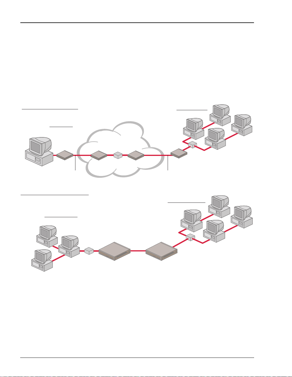
APPLICATIONS
Use the Megabit Modem 310F and 320F for:
• remote access to private networks, for example telecommuting
• point-to-point LAN extension, for example connecting multiple users at a satellite office
to a corporate office LAN
Telecommuting Application
Home office
Local User
ADSL ADSL
LAN Extension Application
Satellite office
Ethernet LAN
Service Provider
310F Router 310F
320F Modem
ADSL
Corporate office
320F Modem320F Modem
Ethernet LAN
Corporate office
310F Modem
Ethernet LAN
2 Megabit Modem 310F and 320F User Man ual
Page 11
INSTALLING THE MEGABIT
MODEM 310F AND 320F
Install a Megabit Modem 310F (ATU-C) at one end of a circuit and a Mega bit Modem 320 F at
the other end (ATU-R), using the procedures described in these sections:
UNPACKING AND INSPECTING THE SHIPMENT
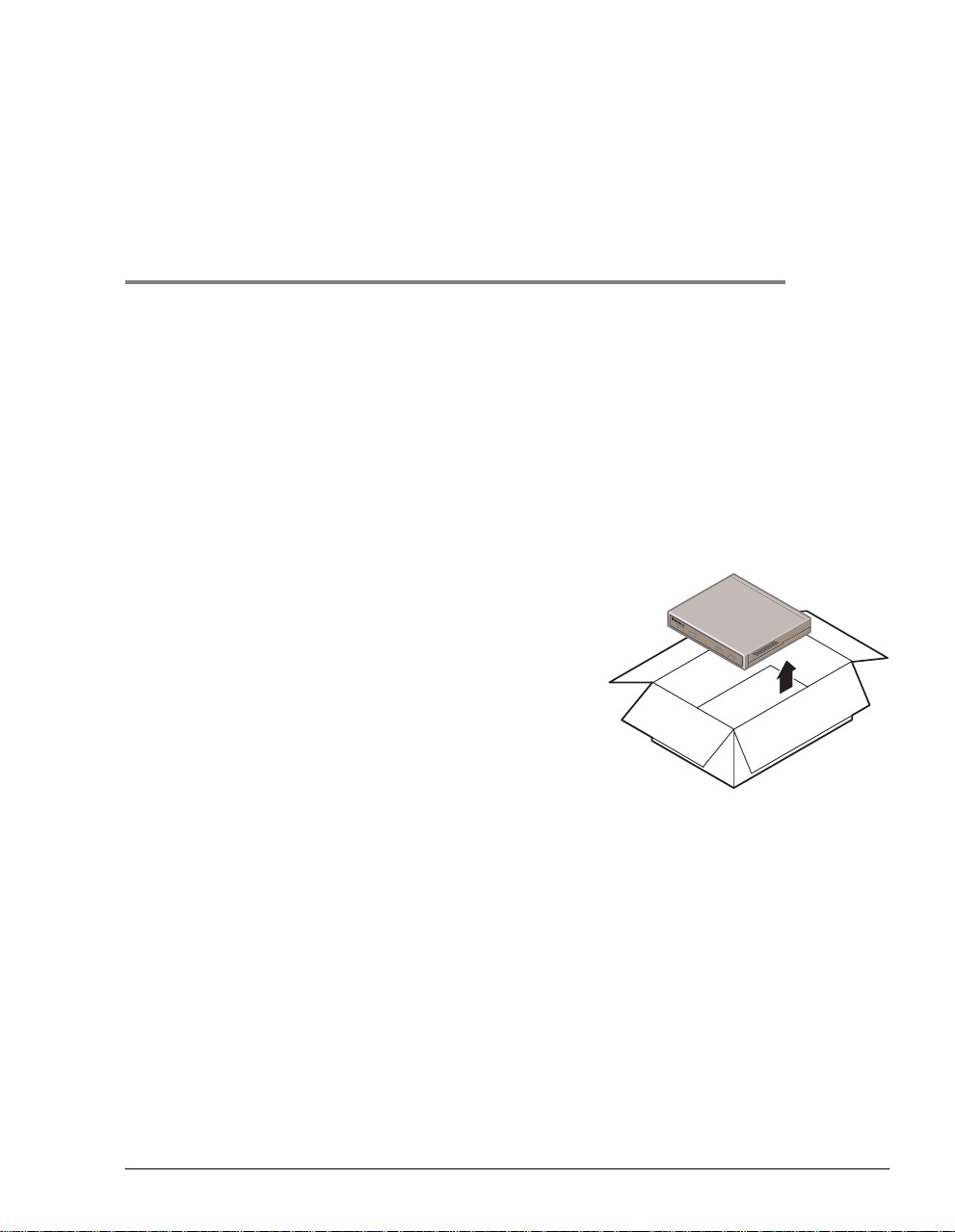
The shipping carton contains the Megabit Modem 310F or 320F, this manual and the items
described on page 4. Upon receipt of the equipment:
1 Unpack each container and visually inspect it for
signs of damage. If the equi pment has been damaged
in transit, immediately report the extent of damage to
the transportation company and to your sales
representative. Order replacement equipment if
necessary.
2 Check the shipment contents against the packing list
to ensure complete and accurate shipment. If the
shipment is short or irregular, contact your sales
representative. If you must store the equipment fo r a
prolonged period, store the equipment in its original container.
LINK
LAN
T
X
R
X COL P
WR
MEGABITMODEM
SY
N
C
SDSL
TX
RX
310F
MAR
2
Megabit Modem 310F and 320F User Man ual 3
Page 12
Attaching the Feet
The shipping carton also contains the items described in the following table.
Item Function
Black cable Connects the modem Ethernet port to a PC NIC using a straight-through cable.
Yellow cable Connects the modem Ethernet port to a network hub using a crossover cable.
Gray ADSL cable Connects the modem ADSL port to an RJ-11 wall jack that has DMT ADSL service.
Gray console
cable and adapter
Universal power
supply
Rubber Feet (4) Attaches to the base of the modem.
Connects the modem RS-232 port to an ASCII terminal or PC running a terminal emulation
program for configuration and management. Cable has RJ-45 connectors. The adapter
converts the RJ-45 port to a DB-9.
Provides primary power to the modem and establishes a safety ground. The Megabit
Modem 310F and 320F are available with a variety of power cords. When you order your
modem, choose one of the following as the last number in the product PN (Megabit Modem
310F is PN 150-2103-7x and Megabit Modem 320F is PN 150-2102-7x) to indicate which
power cord you need:
• 2 does not include a power cord
• 3 includes a North American power cord
• 4 includes a European power cord.
• 5 includes a UK/Ireland power cord
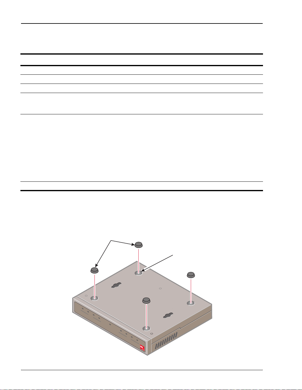
ATTACHING THE FEET
Attach four adhesive-backed rubber feet to the footprint recesses on the bottom of the modem.
Rubber feet
Recess
RX MAR
TX
SDSL
MODEM 310F
SYNC
MEGABIT
PWR
RX COL
LAN
LINK TX
4 Megabit Modem 310F and 32 0F User Manual
Page 13
Chapter 2: Installing the Megabit Modem 3 10F and 320F
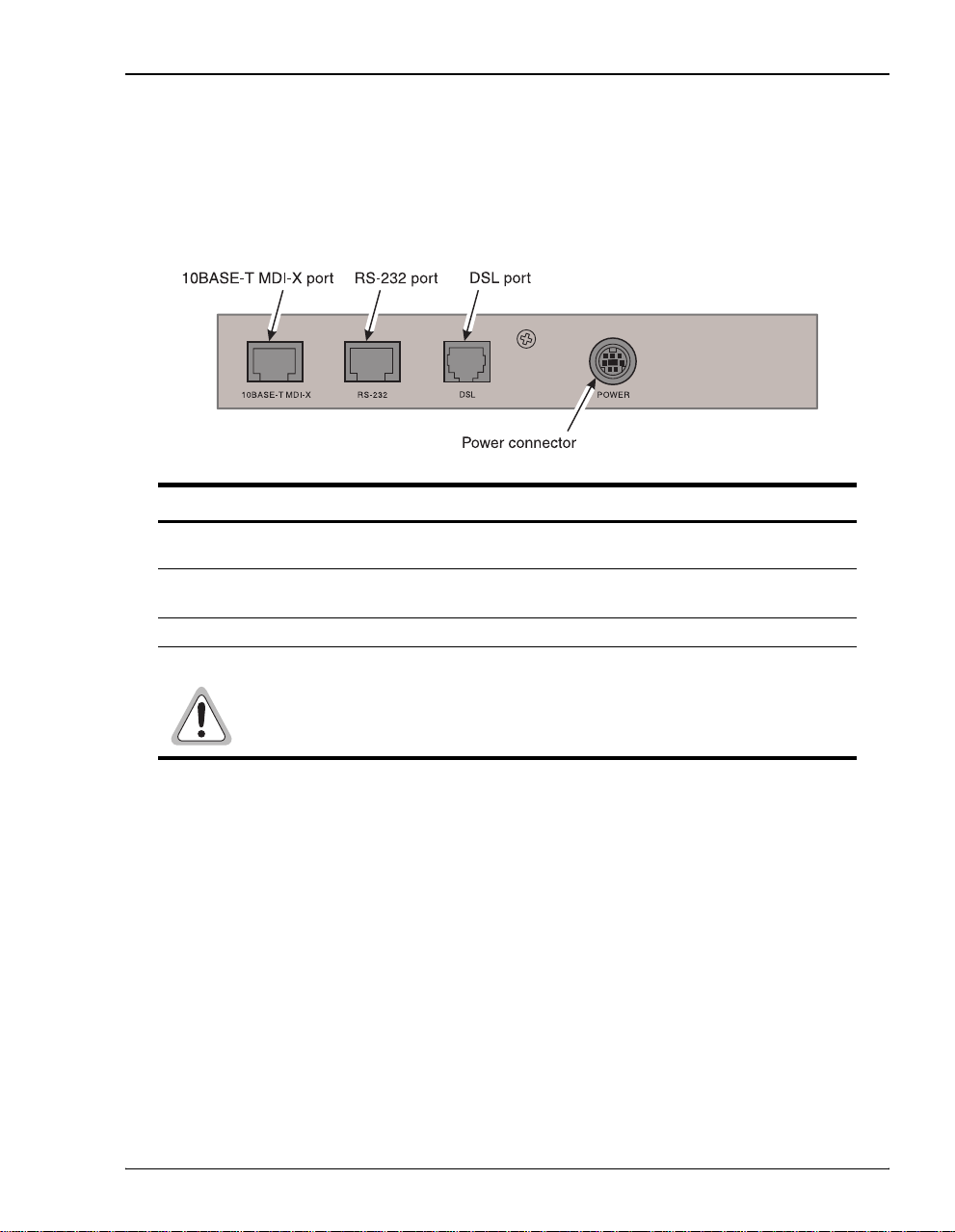
IDENTIFYING THE CONNECTORS
All external connectors are located on the Megabit Modem 310F and 320F rear panel. This
section describes the Megabit Modem 310F and 320F rear panel components.
Component Function
10BASE-T
MDI-X port
RS-232 port RJ-45 port used to connect an ASCII terminal, or PC running a terminal
DSL port RJ-11 port used to connect the modem to the ADSL transmission line.
POWER connector 7-pin DIN port that supplies power to the Megabit Modem 310F and 320F.
RJ-45 port used to connect the modem to the 10BASE-T port of a network hub
or PC NIC.
emulation program, for configuration and management.
Connect only the power s uppl y p r ovid ed to th e Megabit Modem
310F or 320F. Using any oth er po wer supp ly c ould perm anen tly
damage the unit.
Megabit Modem 310F and 320F User Man ual 5
Page 14
Installing the Cabling
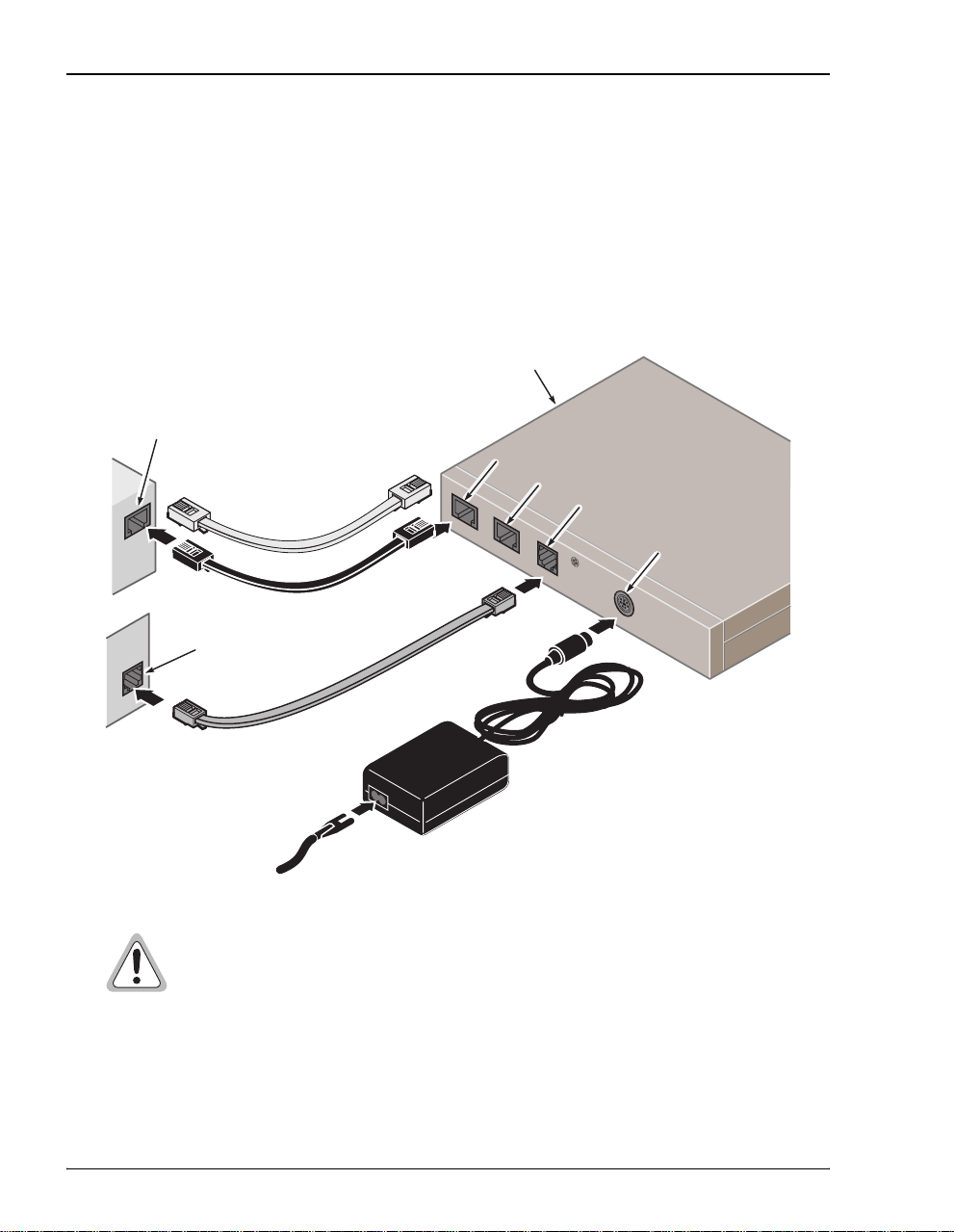
INSTALLING THE CABLING
Use the provided cables as follows:
• black cable or yellow cable—connect to 10BASE-T port for Ethernet LAN connection
• gray ADSL cable—connect to DSL port for ADSL connection
• power supply—connect to power connector
Megabit Modem 310F or 320F
PC, hub or other
network device
10BASE-T port
RS-232 port
DSL port
Wall RJ-11 jack with ADSL
transmission
10BASE-T
RS-232
D
S
L
P
P
O
O
W
W
E
E
R
R
Power
connector
To wall
outlet
Do not connect any other power supply to the Megabit Modem 310F or 320F.
If you use another power supply, you could permanently damage the unit.
See “Connector Pinouts” on page 53 for ADSL and 10BASE-T connector pinouts.
6 Megabit Modem 310F and 32 0F User Manual
Page 15
Chapter 2: Installing the Megabit Modem 3 10F and 320F
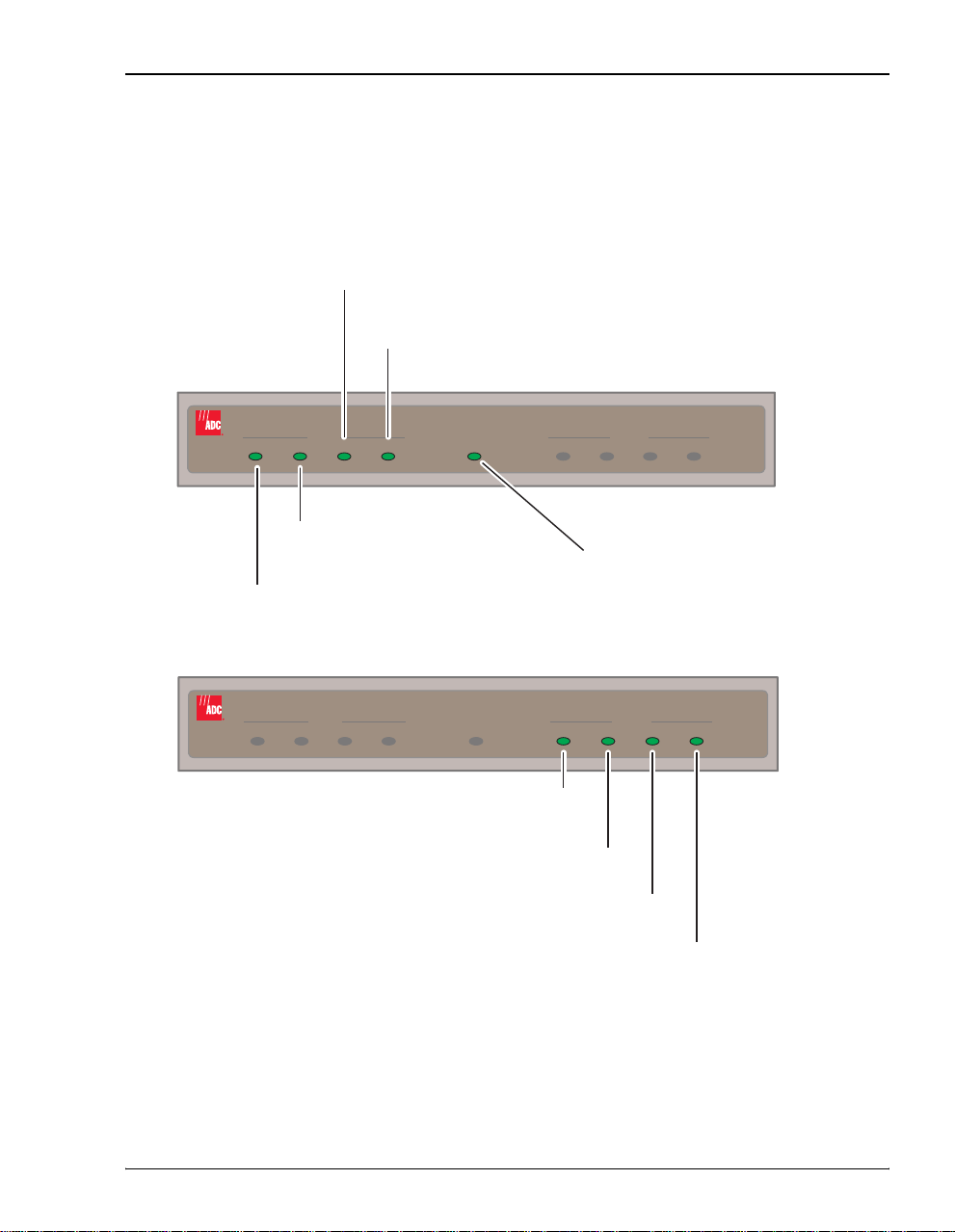
IDENTIFYING LEDS
The front panels for both the Megabit Modem 310F and 320F contain LEDs that indicate power
and data transmission status. The following illustrations describe the front panel LEDs.
Off: No current reception
Flashing: Collision detected
Off: No current collision
LINK TX RX COL PWR SYNC RX MARTX
LAN
Flashing:
Off:
Transmitting a frame
No current transmission
MEGABIT MODEM 320F
On: Network link is up
Off: Link is down
LINK TX RX COL PWR SYNC RX MARTX
LAN
Flashing:
ADSL link dropped
MEGABIT MODEM 320F
Off: No remote modem detected
On:
Link is up
Flashing:
Off:
Transmitting a frame
No current transmission
Flashing:
Off:
No current reception
On:
Margin is at or above configured threshold
Off:
Margin is below configured threshold
ADSL
On: Power is available to the modem
Off: Power is off
ADSL
Receiving a frame
Megabit Modem 310F and 320F User Man ual 7
Page 16

Powering Up and Checking LEDs
Powering Up and Checking LEDs
Once you have completed the steps described in the previous sections for both the Megabit
Modem 310F and 320F, you are ready to power up each modem.
1 Plug the Megabit Modem 310F power supply into the facility power and ensure the
Power LED is lit solid green.
2 Plug the Megabit Modem 320F power supply into the facility power and ensure the
Power LED is lit solid green.
3 Allow the modems approximately 30 to 60 seconds to synchronize.
4 After both modems are powered up, verify the following L ED indicatio ns on each modem:
• 10BASE-T LINK LED is soli d green (when the Ethernet port is connected)
• ADSL SYNC LED is solid green when the Megabit Modem 310F synchronizes wit h
the Megabit Modem 320F (the LED flashes green when synchronization is lost
between the two modems)
• ADSL MAR LED is solid green if margin is at or above the configured threshold
If conditions other than those listed above exist, check the cabling. See “Installing the Cabling”
on page 6 for instructions.
8 Megabit Modem 310F and 32 0F User Manual
Page 17
PREPARING FOR CONFIGURATION
AND
MANAGEMENT
You configure the Megabit Modem 310F and 320F using an ASCII terminal or PC running a
terminal emulation program. This chapter provides the set up procedures.
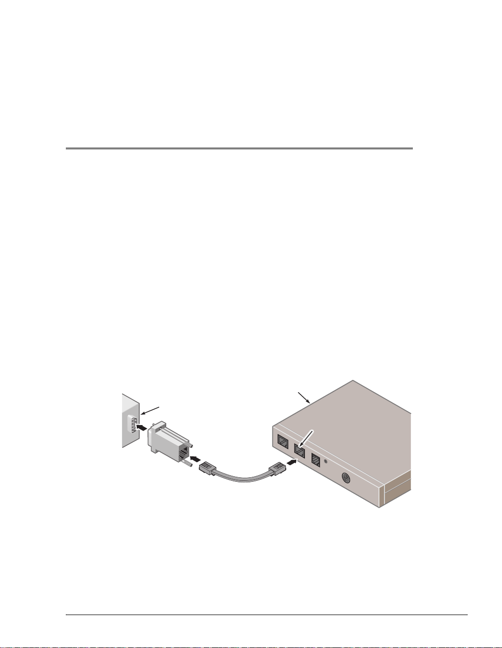
CONNECTING A TERMINAL
Connect the modem to an ASCII terminal or PC running a terminal emulation program:
1 Plug the console adapter into the standard 9-pin COM port on the terminal or PC and
tighten the captive screws until they are snug. (Skip this step if you are using an ASCII
terminal that has an RJ-45 jack.)
2 Connect one end of the gray console cable to the adapter or ASCII terminal RJ-45 jack.
3 Connect the other end of the gray console cable to the modem RS-232 RJ-45 port.
Megabit Modem 310F or 320F
PC
RS-232 port
3
10BASE-T
RS-232
D
S
L
P
P
O
O
W
W
E
E
R
R
Megabit Modem 310F and 32 0F U ser Manual 9
Page 18

Configuring the Terminal
CONFIGURING THE TERMINAL
Whether you are using an ASCII ter minal or PC running a term inal emulation program, such as
Hyperterminal, you must configure the communication settings as indicated in this section,
including designating the connection type and communications port. See your terminal
emulation program or operating system documentation for instructions .
1 Configure these communication settings:
• 9600 to 19,200 baud
• no parity
• 8 data bits
• 1 stop bit
• no flow control
2 Set the terminal em ulation mode to ANSI.
LOGGING ON AND NAVIGATING THE INTERFACE
Using the management interface, you can manage both the Megabit Modem 310F and 320F.
The header on each screen identifies the modem you are currently managing:
• ATU-C is the Megabit Modem 310F.
• ATU-R is the Megabit Modem 320F.
Logging On to the Local Modem
Through the Megabit Modem 310F (ATU-C) System Configuration menu,
you can disable the console port on the Megabit Modem 320F (ATU-R).
Use an ASCII terminal or PC running a terminal emulation program to access
the management interface.
1 Press the several times to activate the autobaud feature and to display the
Logon Password screen.
10 Megabit Modem 310F and 32 0F User Manual
SPACEBAR
Page 19

Chapter 3: Preparing for Configuration and Manageme nt
2 If you have customized your password, type the password at the password prompt.
Otherwise, press which is the factory default password. (See “Changing the Logon
ENTER
Password” on page 17 to customize your password.)
07/20/99 PAIRGAIN TECHNOLOGIES 00:47:59
LOGON PASSWORD>
The
Main Menu displays.
07/20/99 PAIRGAIN TECHNOLOGIES 03:25:24
ATU-C ADSL MEGABIT MODEM TERMINAL v 1.0
ATU-C ADSL MEGABIT MODEM TERMINAL v 1.0
MAIN MENU
1. SYSTEM MENU
2. ADSL MENU
3. BRIDGE MENU
4. REMOTE LOGON
Q. LOGOUT
ENTER CHOICE-->
Megabit Modem 310F and 32 0F U ser Manual 11
Page 20
Logging On and Navigating the Interfa ce
Logging On to the Remote Modem
From the Megabit Modem 310F (ATU-C), you can log on to the Megabit Modem 320F
(ATU-R) to view system parameters and set configuration options in one of the following ways:
• From the Main Menu on the ATU-C, type and the ATU-R Logon screen displays.
• Type to toggle from any ATU-C screen and the ATU-R Logon screen displays.
ATU-C displays
in the header
when logged on
to the Megabit
Modem 310F
ATU-R displays
in the header
when logged on
to the Megabit
Modem 320F
CTRL T
07/20/99 PAIRGAIN TECHNOLOGIES 00:17:43
ATU-C ADSL MEGABIT MODEM TERMINAL v 1.0
ENTER CHOICE-->
07/20/99 PAIRGAIN TECHNOLOGIES 00:17:45
ATU-R ADSL MEGABIT MODEM TERMINAL v 1.0
4
MAIN MENU
1. SYSTEM MENU
2. ADSL MENU
3. BRIDGE MENU
4. REMOTE LOGON
Q. LOGOUT
LOGON PASSWORD>
Once you log on to both the ATU-C and ATU-R modems, type to toggle between the
CTRL T
ATU-C and ATU-R screens to perform configuration or to view status.
When you log on local ly to the Megab it Modem 320F, you can vi ew system param eters and s et
some configuration options for the Megabit Modem 320F only.
12 Megabit Modem 310F and 32 0F User Manual
Page 21
Chapter 3: Preparing for Configuration and Manageme nt
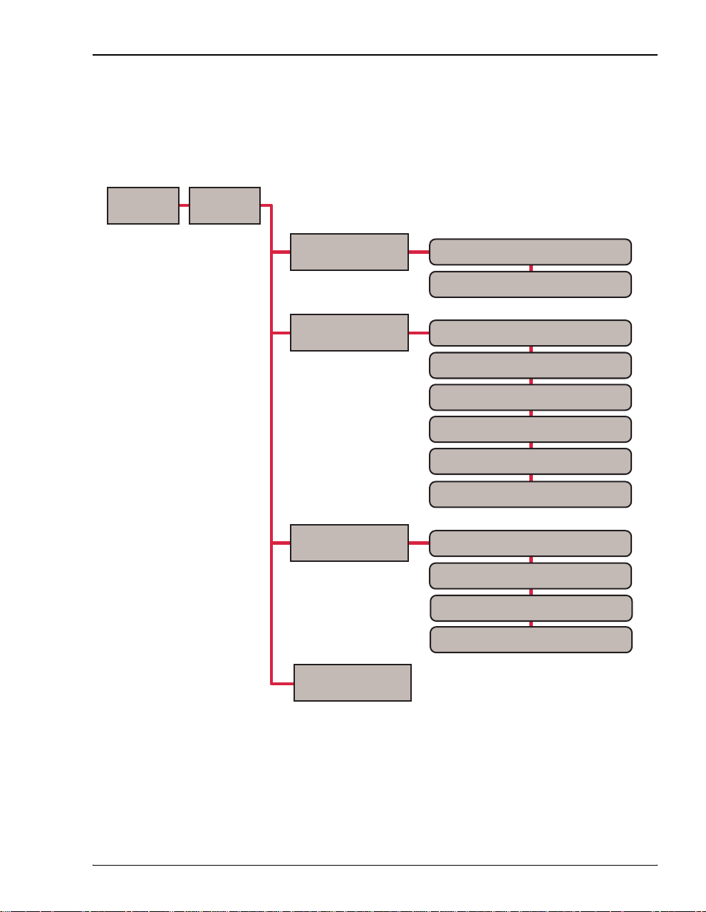
Navigating the Interface
The following illustration shows the Megabit Modem 310F and 320F management interface
structure. Select a menu option by typing the number that precedes it.
Logon
Main Menu
System Menu
ADSL Menu
Bridge Menu
System Information
System Configuration
ADSL Performance Status
24 Hour ADSL Performance History
7 Day ADSL Performance History
ADSL Alarm History
ADSL Transceiver Configuration Menu*
ADSL Link Reset
Bridge Aging Time
Bridge Reset
Bridge Statistics Menu
Source Address Database Menu
Remote Logon
*Read-only field for the Megabit Modem 320F
Megabit Modem 310F and 32 0F U ser Manual 13
Page 22

Logging Off
The following table shows the keyboard functions used to navigate the management interface
and to select menu options.
Key Function
ESC
Restores the selected parameter to the last saved setting. This applies only
to parameters for which you type a value but not to parameters for which
you toggle to select a value.
M
Q
R
CTRL R
CTRL
On performance screens, clears the current performance screen values.
C
Opens the Main Menu.
Logs you off the management interface from the Main Menu.
Returns to the previous menu.
Refreshes the data on the current screen.
Toggles between ATU-C and ATU-R menus.
T
On the ADSL Configuration menu, confirms the new configuration and
suppresses the confirmation prompts.
Selects the next performance screen.
N
Selects the previous performance screen.
P
Restores a previous setting by undoing the last action.
U
You configure Megabit Modem 310F and 320F parameters in two ways:
• Toggle among predefined settings:
1 Type the number preceding a parameter to select it.
2 Press the to toggle among the available settings until the desired se tting
displays, then press .
SPACEBAR
ENTER
• Type required information:
1 Type the number preceding a parameter to select it. A prompt displays.
2 Type the requested informatio n, following the instructions on the screen, then
press .
ENTER
LOGGING OFF
From the Main Menu, type to log off the management interface.
14 Megabit Modem 310F and 32 0F User Manual
Q
Page 23

CONFIGURING THE MODEMS
Configure the Megabit Modem 310F and 320F using an ASCII terminal or PC running a
terminal emulation program connected to the RS-232 port.
SETTING SYSTEM CONFIGURATIONS
From the System Configuration menu, you can set the system time and date, change the pas sword,
and reset the modems to factory default values.
4
1 From the Main Menu (page 11), type to display the System Menu.
07/20/99 PAIRGAIN TECHNOLOGIES 03:25:24
ENTER CHOICE-->
ATU-C ADSL MEGABIT MODEM TERMINAL v 1.0
1. SYSTEM INFORMATION
2. SYSTEM CONFIGURATION
1
SYSTEM MENU
(M)ain
Megabit Modem 310F and 32 0F U ser Manual 15
Page 24

Setting System Configurations
2 Type to display the System Configuration menu.
2
07/20/99 PAIRGAIN TECHNOLOGIES 03:25:24
ENTER CHOICE-->
ATU-C ADSL MEGABIT MODEM TERMINAL v 1.0
SYSTEM CONFIGURATION
1. CHANGE SYSTEM TIME
2. CHANGE SYSTEM DATE
3. CHANGE PASSWORD
4. FACTORY DEFAULT CONFIGURATION
5. ATU-R LOGIN ENABLED
(R)eturn (M)ain
Changing the System Time
1 From the System Configuration menu, type to select Change System Time.
The following message displays: Please enter a new time: HH:MM:SS
1
2 At t he system prompt, type the new time in specified two-digit 24-hour format, then
press .
ENTER
The new time displays in the upper right corner of the screen.
Changing the System Date
1 From the System Configuration menu, type to select Change System Date.
The following message displays: Please enter a new date: MM:DD:YY
2 At the system prompt, type the new month, day and year in the specified two-d igit numeric
format, then press .
ENTER
The new date displays in the upper left corner of the screen.
16 Megabit Modem 310F and 32 0F User Manual
2
Page 25

Chapter 4: Configuring the Modems
Changing the Logon Password
1 From the System Configuration menu (page 16), type to select Change Password.
3
The following message displays: Creating user password, press ENTER
2 Press .
ENTER
The following prompt displays: Please enter the new password
3 At the system pro mpt, type the new password, using up to eight characters, then press
. (An * displays as you type each character.)
ENTER
After you press , the following prompt displays: Please retype the new
ENTER
password
4 At the system prompt, type the new password again, then press
ENTER
.
The following prompt displays: Password accepted
If you change the default pa ssword, wri te it down and sav e it in a secure plac e.
If you forget your new password, you will be unable to log on to the modem.
Megabit Modem 310F and 32 0F U ser Manual 17
Page 26

Setting System Configurations
Restoring Factory Default Settings
The following table summarizes the factory default settings. The procedure restores all settings
to their factory defaults.
Setting Factory Default
System
Logon Password
ATU-R Login (Megabit Modem 320F
Craft Port Access)
Startup Mode Adaptive Rate
Margin 4 dB
Upstream Data Rate 928 kbps - maximum
Downstream Data Rate 7040 kbps - maximum
SNR Margin Threshold 3 dB
ES Threshold 100
Alarm Severity E, enabled as a minor alarm
Interleave 4 ns
Bridging
Bridge Aging Time 300
ENTER
Enable
ADSL
64 kbps - minimum
64 kbps - minimum
1 From the
System Configuration menu (page 16), type to select Factory Default Configuration.
4
The following message disp lays: This will reset all the configurations
and the ADSL modem. Are you sure? (Y/N)
2 Do one of the following:
• Type to reset the modem. When you type , the modem restarts with the factory
Y Y
default settings in effect. The following message displays: NVRAM Updated.
• Type to discontinue this procedure.
18 Megabit Modem 310F and 32 0F User Manual
N
When you select yes to restore the factory default configuration, the modem
automatically writes the factory default valu es to NVRAM and resets the ADSL
link between the Megabit Mo dem 310F and 320F . You are automatically logg ed
off the modem(s) and must log on again.
Page 27

Chapter 4: Configuring the Modems
3 If you typed to restore factory default settings, you must pres s the several
Y SPACEBAR
times to display the Logon screen. Then, log on to the modem(s).
Disabling or Enabling the RS-232 Port For the Megabit Modem 320F
You can enable or disable the RS-232 port for the Megabit Modem 320F from the
Megabit Modem 310F management interface. The screen op tio n is
setting is
1 From the
Enabled.
The ATU-R Login option displays for the remote modem only when you are
logged on to the Megabit Modem 310F (ATU-C).
The current status of the M egabit Modem 32 0F RS-232 port (enab le or disab le)
displays to the right of the ATU-R Login option.
System Configuration menu, type to select a new ATU-R Login option. (When the
RS-232 port status is
07/20/99 PAIRGAIN TECHNOLOGIES 05:14:24
ENABLED, it changes to DISABLED after typing .)
ATU-C ADSL MEGABIT MODEM TERMINAL v 1.0
SYSTEM CONFIGURATION
5
ATU-R Login and the default
5
1. CHANGE SYSTEM TIME
2. CHANGE SYSTEM DATE
3. CHANGE PASSWORD
4. FACTORY DEFAULT CONFIGURATION
5. RT LOGIN
ENTER CHOICE-->
2 Press to confirm the new
ENTER
displays to the right of
Megabit Modem 310F and 32 0F U ser Manual 19
Press RETURN to confirm, ESC to cancel
ATU-R Login.
(R)eturn (M)ain
ATU-R Login option for the RS-232 port. The new option
DISABLED
Page 28

Configuring ADSL Service
CONFIGURING ADSL SERVICE
You configure ADSL transceiver service from the Megabit Modem 310F
(ATU-C) only. The ADSL Configuration Menu items are read-only from the
Megabit Modem 320F (ATU-R). You must re set the ADSL Link to activate ADSL
configuration changes (page 26).
This section describes how to configure ADSL data transmission parameters.
1 From the
07/20/99 PAIRGAIN TECHNOLOGIES 03:25:24
ENTER CHOICE-->
2 From the
07/20/99 PAIRGAIN TECHNOLOGIES 00:26:09
ENTER CHOICE-->
Main Menu (page 11), type to display the ADSL Menu.
ATU-C ADSL MEGABIT MODEM TERMINAL v 1.0
1. ADSL PERFORMANCE STATUS
2. 24 HOUR ADSL PERFORMANCE HISTORY
3. 7 DAY ADSL PERFORMANCE HISTORY
4. ADSL ALARM HISTORY
5. ADSL CONFIGURATION MENU
6. ADSL LINK RESET
ADSL Menu, type to display the ADSL Configuration Menu.
1. STARTUP OPTION ADAPTIVE RATE
2. (MAX) UP DATA RATE 928 ( 64 - 928 Kbps)
3. (MAX) DOWN DATA RATE 7040 ( 64 - 7040 Kbps)
4. (MIN) UP DATA RATE 64 ( 64 - 928 Kbps)
5. (MIN) DOWN DATA RATE 64 ( 64 - 7040 Kbps)
6. STARTUP SNR MARGIN 4dB
7. MARGIN THRESHOLD 3
8. ES THRESHOLD 100
9. ALARM CONFIGURATION LOF=E MAR=E ES=E SES=E LOS=E SELF=E
A. UP INTERLEAVE OPTION 4 msec
B. DOWN INTERLEAVE OPTION 4 msec
5
ATU-C ADSL MEGABIT MODEM TERMINAL v 1.0
(U)ndo (R)eturn (M)ain
2
ADSL MENU
(M)ain
ADSL CONFIGURATION MENU
20 Megabit Modem 310F and 32 0F User Manual
Page 29

Chapter 4: Configuring the Modems
Configuring the Startup Settings
You can configure these se ttings only from th e M egab it M odem 31 0F for both
the Megabit Modem 310F and 320F. The fields ar e
when you access them through the management interface for the Megabit
Modem 320F.
You configure the Startup Option and Startup SNR Margin to establish how the modem comes
up to achieve a transmission rate after a reset (see page 26 for resetting the modem).
Select the Startup Option
Read Only Parameters
1 From the ADSL Configuration Menu (page 20), type to select Startup Option.
2 Press the to sequence to the
SPACEBAR ENTER
Startup Option you want, then press .
1
The startup option determines how an ADSL transmission rate is established when
the modem is reset. The default is Adaptive Rate. The following table describes the
available options.
Startup Option Description
Adaptive Rate The modem comes up at the highest possible data rate based on the
configured startup margin and line conditions. Adaptive Rate is the default.
Fixed Rate At startup, the system attempts only the rates you configure in “Configuring
Data Rates” on page 22, which include maximum upstream and downstream
data rates with a margin greater than or equal to the configured margin. If the
data rates cannot be obtained, the system continues to attempt the data rate.
If it does not achieve the data rate, the modems will not sync.
Select the Startup SNR Margin
1 From the ADSL Configuration Menu (page 20), type to select Startup SNR Margin.
2 Press the to sequence to the
press .
SPACEBAR
ENTER
Startup SNR Margin value you want, then
The Startup SNR Margin is the margin that the modem must achieve to come up. The
available values range from 0 to 15 dB. The default is 4 dB.
6
Megabit Modem 310F and 32 0F U ser Manual 21
Page 30

Configuring ADSL Service
Configuring Data Rates
You can configure the data rate on ly from the Megabit Modem 310F for both the
Megabit Modem 310F and 320F. The data rate fields are
Parameters when you access them from the Megabit Modem 320F (ATU-R).
You configure the minimu m and maximum data rates f or both upstream and downstr eam traffic.
The maximum data rates determine the rate the modem must achieve to come up when the
startup option is set to Fixed Rate (see page 21).
1 Configure the upstream data rates (transmission toward the Megabit Modem 310F):
Read Only
a From the
ADSL Configuration Menu (page 20), type to select (Max) Up Data Rate.
2
The following message displays: Enter valid input
b Type a maximum upstream data rate, in kbps, then press .
ENTER
The valid data rate values are increments of 32 between 64 and 928 kbps . If you enter
a value that is not an increment of 32, the modem automatically adjusts it to the closest
increment of 32. The default is 928 kbps.
c Type to select (
4
Min) Up Data Rate.
The following message displays: Enter valid input
d Type a minimum upstream data rate, in kbps, then press .
ENTER
The valid data rate values are increments of 32 between 64 and 928 kbps . If you enter
a value that is not an increment of 32, the modem automatically adjusts it to the closest
increment of 32. The default is 64 kbps.
2 Confi gur e the downstream data rates (transmission toward the Megabit Modem 320F):
a From the
ADSL Configuration Menu (page 20), type to select (Max) Down Data Rate.
3
The following message displays: Enter valid input
b Type a maximum downstream data rate, in kbps, then press .
ENTER
The valid data rate values are increments of 32 between 64 kbps and 7040 kbps. If you
enter a value that is not an increment of 32, the modem automatically adjusts it to the
closest increment of 32. The default is 7040 kbps.
22 Megabit Modem 310F and 32 0F User Manual
Page 31

Chapter 4: Configuring the Modems
c Type to select (Min) Down Data Rate.
5
The following message displays: Enter valid input
d Type a maximum downstream data rate, in kbps, then press .
ENTER
The valid data rate values are increments of 32 between 64 kbps and 7040 kbps. If you
enter a value that is not an increment of 32, the modem automatically adjusts it to the
closest increment of 32. The default is 64 kbps.
Configuring the SNR Margin Threshold
The margin threshold determines the SNR margin value below which an SNR margin alarm
occurs and the MAR LED on the modem front panel turns off.
1 From the ADSL Configuration Menu (page 20), type to select Margin Threshold.
7
The following message displays: Enter Valid Input
2 Type an SNR dB value between 0 and 15, then press .
ENTER
The default value is 3 dB.
Configuring the ES Threshold
The ES (Errored Seconds) Threshold is the number of acceptable seconds in a 15-minute
interval during which errors occur. If the number of errored seconds in the 15-minute interval
exceeds this value, an ES alarm occurs.
1 From the
ADSL Configuration Menu (page 20), type to select ES Threshold.
8
The following message displays: Enter valid input
2 Type an ES threshold value between 0 and 255, then press .
ENTER
The default value is 100.
Megabit Modem 310F and 32 0F U ser Manual 23
Page 32

Configuring ADSL Service
Configuring Alarms
You can configure the severity of each modem alarm, or disable alarms.
1 From the
2 Type to move to the next alarm type until you select the one you want to configu re.
ADSL Configuration Menu (page 20), type to select Alarm Configuration.
N
9
The following table identifies the available alarm types.
Alarm Type Description
LOF Loss of Frame
MAR Margin
ES Errored Seconds
SES Severely Errored Seconds
LOS Loss of Signal
SELF Self test failed
3 Press the to toggle to the setting y ou want for the alarm, then press .
SPACEBAR ENTER
The following table describes the available alarm settings. The default for each alarm is E.
Setting Description
E Enables the alarm as a minor alarm.
M Enables the alarm as a major alarm.
D Disables the alarm.
24 Megabit Modem 310F and 32 0F User Manual
Page 33

Chapter 4: Configuring the Modems
Configuring the Interleave Options
It is important to note that an increase in impulse noise immunity causes an
increase in delay.
Use the interleave option to increase impulse noise immunity. The delay is in milliseconds for
both the Up and Down Interleave Options (upstream and downstream traffic).
1 From the ADSL Configuration Menu (page 20), type to select Up Interleave Option.
2 Press the to toggle to the interleave value you want, then press .
SPACEBAR ENTER
A
The available options are 0, 2, 4, 8 and 16 msec. The recommended interleave delay is
4 msec, to achieve maximum transmission rates with adequate noise im m unity. The
default is 4.
3 Type to select
4 Press the to toggle to the interleave value you want, then press .
B
SPACEBAR ENTER
Down Interleave Option.
The available options are 0, 2, 4, 8 and 16 msec. The recommended interleave delay is
4 msec, to achieve minimum latency with adequate noise immunity. The default is 4.
Saving ADSL Configuration Changes
After you make changes to ADSL configuration from the ADSL Configuration Menu (page 20),
you must either accept or not accept these changes before you can return to
(page 20).
1 When you finish making changes to ADSL configuration, type or to exit the
ADSL Menu.
The following prompt displays: Save current settings (Y/N)?
2 Type to save the changes you made or type to not save the changes you made.
Y N
ADSL Menu
M R
You return to the
Megabit Modem 310F and 32 0F U ser Manual 25
ADSL Menu.
Page 34

Configuring ADSL Service
Resetting the ADSL Link
After you make any ADSL configuration changes, you must reset the ADSL link to activate the
new configuration and reestablish the ADSL link .
1 From the ADSL Menu (page 20), type to reset the ADSL link.
6
The following prompt displays : This will bring down the ADSL link. Are
you sure (Y/N)?
When you select yes, the modem automatically resets the ADSL link between
the Megabit Modem 310F and 320F. You are automatically logged off the
modem(s) and must log on again.
2 Do one of the following:
• Type to reset the ADSL link.
Y
The following message displays: ADSL link reset
• Type if you do not want to reset the modem. (If you do not rese t the mode m, ADSL
N
configuration changes you made are not activated.)
26 Megabit Modem 310F and 32 0F User Manual
Page 35

Chapter 4: Configuring the Modems
CONFIGURING BRIDGE PARAMETERS
Configure the Ethernet bridging parameter s. The LAN mode for the Megabit Modem 310F and
320F is half duplex.
1 On the Main Menu (page 11), type to display the Bridge Menu.
09/09/99 PAIRGAIN TECHNOLOGIES 03:36:55
ENTER CHOICE-->
ATU-C ADSL MEGABIT MODEM TERMINAL v 1.0
LAN LINK STATUS UP
1. BRIDGE AGING TIME 300 SECONDS
2. BRIDGE RESET
3. BRIDGE STATISTICS MENU
4. SOURCE ADDRESS DATABASE MENU
3
BRIDGE MENU
(M)ain
Configuring Bridge Aging Time
The Bridge Aging Time determines the interval at which the modem checks the bridging table
for unused addresses and marks those addresses as invalid. The default is 300 seconds.
1 Type to select Bridge Aging Time.
2 Type the value in seconds (valid range is from 1 to 511) that you want, then press .
Megabit Modem 310F and 32 0F U ser Manual 27
2
ENTER
Page 36

Configuring Bridge Parameters
Configuring the Source Address Database
The source address database can contain up to 8,192 entries. Addresses can be entered either
automatically through address learning on the LAN port, or manually. Each address is
mapped to a 10-bit key, which is used to group the addresses into 1,024 separate buckets
containing up to eight addresses in each bucket. T his reduces the search time re quired to locate
an address in the address table by requiring the processor to search only one bucket, or a
maximum of eight addresses.
1 From the Bridge Menu, type to display the
08/12/99 PAIRGAIN TECHNOLOGIES 03:45:44
1. READ ALL VALID MAC ENTRIES 4. CREATE STATIC MAC ADDRESS ENTRY
2. READ ENTRY BY MAC ADDRESS 5. DELETE STATIC MAC ADDRESS ENTRY
3. READ BUCKET 6. DISPLAY ALL STATIC MAC ADDRESS ENTRIES
BUCKET NUMBER = 0 TYPE VALID MAC ADDRESS
ENTER CHOICE-->
ATU-C ADSL MEGABIT MODEM TERMINAL v 1.0
SOURCE ADDRESS DATABASE MENU
---- ----- -----------
-- INV 00:00:00:00:00:00
-- INV 00:00:00:00:00:00
-- INV 00:00:00:00:00:00
-- INV 00:00:00:00:00:00
-- INV 00:00:00:00:00:00
-- INV 00:00:00:00:00:00
-- INV 00:00:00:00:00:00
-- INV 00:00:00:00:00:00
(R)eturn (M)ain (N)ext (P)revious (U)pdate
Source Address Database Menu.4
28 Megabit Modem 310F and 32 0F User Manual
Page 37

Chapter 4: Configuring the Modems
The following table describes the data displayed on the Source Address Database Menu.
Column Description
TYPE Indicates the method by which the entry was added to the table.
DYN Dynamic is automatically learned by the LAN port.
STAT Static is entered manually.
--- Indicates that the table row is empty.
VALID VAL - Indicates that the entry is valid and being used.
MAC ADDRESS The MAC address associated with the parameters contained in that
The options are:
INV - Indicates that the entry is not being used.
row of the bridging table.
2 To view all valid Bridge Address Table entries by MAC address:
a Type to select
1
Read All Valid MAC Entries.
The message displays: Searching Database
Eight entries, that result from the search, display. The bucket number indicates the
last bucket searched.
The message displays: Press C to Continue Searching
b Type to display the next eight entries of the search.
C
When no more entries are found in the database, the message displays:
Search Finished
3 To view a Bridge Address Table entry by MAC address:
a Type to select
2
Read Entry by MAC Address.
The message displays: Please enter MAC Address
(aa:bb:cc:dd:ee:ff)
b Type the MAC address, then press .
ENTER
4 To view all the entries in a specific bucket:
a Type to select
3
Read Bucket.
The message displays: Please enter bucket number
b Type the desired bucket number, then press .
Megabit Modem 310F and 32 0F U ser Manual 29
ENTER
Page 38

Configuring Bridge Parameters
5 To add a static MAC address to the Bridge Address Table:
a Type to select
4
Create Static MAC Address Entry.
The message displays: Please enter MAC Address
(aa:bb:cc:dd:ee:ff)
b Type the MAC address, then press .
c Type to update the data in the current bucket, or type to Display All
U 6
ENTER
Static MAC Address Entries.
6 To delete a static MAC address from the Bridge Address Table:
a Type to select
5
Delete Static MAC Address Entry.
The message displays: Please enter MAC Address
(aa:bb:cc:dd:ee:ff)
b Type the MAC address, then press .
ENTER
The MAC address you just deleted displays:
MAC address = aa:bb:cc:dd:ee:ff
c Type to update the data in the current bucket, or type to Display All
U 6
Static MAC Address Entries.
7 To view all Bridge Address Table static MAC entries:
a Type to select
6
Display All Static MAC Entries.
The message displays: Searching Database
Eight entries, that result from the search, display. The bucket number indicates the
last bucket searched.
The message displays: Press C to Continue Searching
b Type to display the next eight entries of the search.
C
When no more entries are found in the database, the message displays:
Search Finished
Resetting the Bridge
Use the Bridge Reset option to reset the modem bridge function. Under rare conditions, the
bridge func tion may stop forwarding frames. If the DSL link is up and no errored seconds are
accumulating, but Ethernet data is not passing through the modem, a bridge reset on either the
ATU-C or ATU-R unit may resolve the problem.
30 Megabit Modem 310F and 32 0F User Manual
Page 39

MONITORING CIRCUIT STATUS
AND
DISPLAYING SYSTEM
INFORMATION
Monitor circuit status for the Megabit Modem 310F and 320F using an ASCII terminal or PC
running a terminal emulation program, connected to the RS-232 port.
MONITORING ADSL STATUS
From the Main Menu (page 11), type to display the ADSL Menu. From this menu, you can select
items 1 through 4 to provide status on the ADSL link, as described in the following sections.
07/20/99 PAIRGAIN TECHNOLOGIES 03:25:24
ATU-R ADSL MEGABIT MODEM TERMINAL v 1.0
5. ADSL CONFIGURATION MENU
2
ADSL MENU
1. ADSL PERFORMANCE STATUS
2. 24 HOUR ADSL PERFORMANCE HISTORY
3. 7 DAY ADSL PERFORMANCE HISTORY
4. ADSL ALARM HISTORY
6. ADSL LINK RESET
5
(M)ain
ENTER CHOICE-->
Megabit Modem 310F and 32 0F U ser Manual 31
Page 40

Monitoring ADSL Status
Monitoring ADSL Performance Status
The ADSL Performance Status screen is updated every second and provides a summary of the
current ADSL status, including alarms, for both upstream and downstream traffic. The SNR
(signal-to-noise ratio) Margin row displays both the current SNR margins and the minimum
SNR margins for the current 24-hour data collection period.
ADSL Menu (page 31), type to display the ADSL Performance Status scre e n.
On the
07/20/99 PAIRGAIN TECHNOLOGIES 03:25:24
DOWN ALARMS: NONE
UP ALARMS: NONE
SYSTEM STATE: DATA
SNR MARGIN (dB): 16.0/15.1 4.1/3.9
LINE ATTN (dB): 4.60 0.9
24 HOUR ES: 0 0
24 HOUR UAS: 0 0
DATA RATE (kbps): 7040 800
ENTER CHOICE-->
Type to clear the ADSL performance and alarm counters in both the Megabit Modem 310F
C
ATU-R ADSL MEGABIT MODEM TERMINAL v 1.0
1
ADSL PERFORMANCE STATUS
DOWNSTREAM UPSTREAM
---------- -------cur/min cur/min
(C)lear (R)eturn (M)ain
and 320F. See the table on page 33 for a definition of each status field.
32 Megabit Modem 310F and 32 0F User Manual
Page 41

Chapter 5: Monitoring Circuit Statu s and D isp layi ng System Information
The following table describes the data displayed on the ADSL Performance Status screen.
Field Meaning
Down Alarms Identifies the current downstream alarms (toward the Megabit
Modem 320F). Options:
• LOF - Loss of Frame
• LOS - Loss of Signal
• MAR - Margin
• ES - Errored Seconds
• SES - Severely Errored Seconds
• SELF - Self Test Failed
• NONE - No current alarms
Up Alarms Identifies the current upstream alarms (transmission toward the
Megabit Modem 310F).
System State Identifies the state of the ADSL system:
• ACK - Acknowledge during handshake.
• TRAINING - Modem is currently training.
• CHANA - Channel analysis is in process.
• EXCH - Exchange final handshaking messages.
• DATA - Link is up and data can be transferred.
SNR Margin (dB) Identifies the current (cur) and minimum (min) margin values for
the ADSL loop for the current 24-hour period. See “Reach, Data
Rate, SNR Margin, and Noise Environment” on page 48 for
information on SNR margin and BER.
Line Attn (dB) Indicates the line attenuation for the upstream and downstream
ADSL channels. Line attenuation is the decrease in amplitude of the
signal between transmission and receipt.
24 Hour ES Indicates the total number of errored seconds that were detected on
the ADSL link during the current 24-hour period.
24 Hour UAS Indicates the total number of unavailable seconds (UAS) that were
detected on the ADSL link during the current 24-hour period. UAS
indicate the amount of time that the lines were unavailable for
transmission since the modem was powered up or cleared.
Data Rate (kbps) Identifies the current rates at which data is being transmitted.
Megabit Modem 310F and 32 0F U ser Manual 33
Page 42

Monitoring ADSL Status
Monitoring 24 Hour ADSL Performance History
The 24 Hour ADSL Performance History report consists of eight screens. Each screen displays three
hours of data, in 15-minute increments. Together, the eight screens provide a summary of the
24-hour performance history.
From the
ADSL Menu (page 31), type to open the 24 Hour ADSL Performance History screen.
07/20/99 PAIRGAIN TECHNOLOGIES 03:25:24
ENTER CHOICE-->
ATU-R ADSL MEGABIT MODEM TERMINAL v 1.0
24 HOUR ADSL PERFORMANCE HISTORY
(errored seconds/unavailable seconds/snr)
DOWNSTREAM UPSTREAM
02:45 000/000/15.5 000/000/3.9
02:30 000/000/16.0 000/000/3.9
02:30 000/000/ NA 000/000/ NA
02:30 000/000/ NA 000/000/ NA
02:45 000/000/ NA 000/000/ NA
02:30 000/000/ NA 000/000/ NA
02:30 000/000/ NA 000/000/ NA
02:30 000/000/ NA 000/000/ NA
02:45 000/000/ NA 000/000/ NA
02:30 000/000/ NA 000/000/ NA
02:30 000/000/ NA 000/000/ NA
02:30 000/000/ NA 000/000/ NA
(C)lear (P)revious (N)ext (R)eturn (M)ain
To clear all ES and UAS counts, including the equivalent counts in the remote unit, type . The
2
C
minimum SNR for the period is reset to the current SNR.
The 24 Hour ADSL Performance History data is lost when the modem is
turned off.
34 Megabit Modem 310F and 32 0F User Manual
Page 43

Chapter 5: Monitoring Circuit Statu s and D isp layi ng System Information
Monitoring 7 Day ADSL Performance History
The 7 Day ADSL Performance History menu displays the ES and UAS counts, and the minimum
SNR margins for the current day and the prev i ous six days. Each day begi ns at 12 A.M.
midnight, therefore the current day count is not necessarily equal to the count for the past 24
hours.
From the
ADSL Menu (page 31), type to open the 7 Day ADSL Performance History screen.
07/20/99 PAIRGAIN TECHNOLOGIES 03:25:24
ENTER CHOICE-->
ATU-R ADSL MEGABIT MODEM TERMINAL v 1.0
7 DAY ADSL PERFORMANCE HISTORY
(errored seconds/unavailable seconds/snr)
01/01/99 00000/00000/ 20.4 00000/00000/ 4.1
12/31/98 00000/00000/ NA 00000/00000/ NA
12/30/98 00000/00000/ NA 00000/00000/ NA
12/29/98 00000/00000/ NA 00000/00000/ NA
12/28/98 00000/00000/ NA 00000/00000/ NA
12/27/98 00000/00000/ NA 00000/00000/ NA
12/26/98 00000/00000/ NA 00000/00000/ NA
To clear all ES and UAS counts, including the equivalent counts in the remote unit, type .
3
DOWNSTREAM UPSTREAM
(C)lear (R)eturn (M)ain
C
The minimum SNR for the period is reset to the current SNR.
The 7 Day ADSL Performance History data is lost when the modem is turned off.
Megabit Modem 310F and 32 0F U ser Manual 35
Page 44

Monitoring ADSL Status
Monitoring ADSL Alarm History
The ADSL Alarm History screen displays the current status and first and last occurrence of each
ADSL alarm type.
From the ADSL Menu (page 31), type on the ADSL Menu to o pen the ADSL Alarm History
4
screen.
07/20/99 PAIRGAIN TECHNOLOGIES 03:25:24
Type First Last Curr Time(s)
LOF, DOWN OK
LOF, UP OK
MARGIN, DOWN OK
MARGIN, UP OK
ES, DOWN OK
ES, UP OK
SES, DOWN OK
SES, UP OK
LOS, DOWN OK
LOS, UP OK
SELFTEST OK
LAST CLEARED 07/20/99-02:06:14
ENTER CHOICE>
Type to clear the first and last date/time stamps.
C
ATU-R ADSL MEGABIT MODEM TERMINAL v 1.0
ADSL ALARM HISTORY
(C)lear (R)eturn (M)ain
The Alarm History data is lost when the Megabit Modem 310F is turned off.
36 Megabit Modem 310F and 32 0F User Manual
Page 45

Chapter 5: Monitoring Circuit Statu s and D isp layi ng System Information
The following table describes the information displayed on the ADSL Alarm History screen.
Name Description
Type Identifies local, remote, and ADSL link alarms:
• LOF: Loss of frame failure
• MARGIN: Low SNR margin alarm
• ES: Errored seconds
• SES: Severely errored seconds
• LOS: Loss of signal
• SELFTEST: Whether the self test was successful or not.
• LAST CLEARED: The time the screen was last cleared.
First Lists the first time an alarm is detected.
Last Lists the last time an alarm was detected.
Current Identifies the current status of the alarm.
Time(s) Lists the time in seconds that any alarm occurred.
Megabit Modem 310F and 32 0F U ser Manual 37
Page 46

Monitoring Ethernet Bridge Statistic s
MONITORING ETHERNET BRIDGE STATISTICS
The Megabit Modem 310F and 320F provide real-time, non-disruptive monitoring of system
performance. The display is updated every second.
1 From the Main Menu (page 11), type to open the Bridge Menu.
08/12/99 PAIRGAIN TECHNOLOGIES 00:15:45
ENTER CHOICE-->
ATU-C ADSL MEGABIT MODEM TERMINAL v 1.0
LAN LINK STATUS UP
1. BRIDGE AGING TIME 300 SECONDS
2. BRIDGE RESET
3. BRIDGE STATISTICS MENU
4. SOURCE ADDRESS DATABASE MENU
2
BRIDGE MENU
(M)ain
38 Megabit Modem 310F and 32 0F User Manual
Page 47

Chapter 5: Monitoring Circuit Statu s and D isp layi ng System Information
2 From the Bridge Menu, type to open the Bridge Statistics Menu.
08/12/99 PAIRGAIN TECHNOLOGIES 00:02:32
LAN PORT WAN PORT BRIDGE
RX BYTES 252436 RX BYTES 0 ENTRIES LEARNED 20
RX FRAMES 1476 RX FRAMES 0 ENTRIES NOT LEARNED 0
RX MCASTS 922 RX DISCARDS 0 LAN FILTERED FRAMES 99
RX DISCARDS 1186 RX ERRORS 0
RX ERRORS 0 RX BIG 0
RX SMALL 0
RX BIG 0
TX BYTES 0 TX BYTES 0
TX FRAMES 0 TX FRAMES 0
TX MCASTS 0
TX EX COLS 0
ENTER CHOICE-->
3
ATU-C ADSL MEGABIT MODEM TERMINAL v 1.0
BRIDGE STATISTICS MENU
(R)eturn (M)ain (C)lear
Megabit Modem 310F and 32 0F U ser Manual 39
Page 48

Monitoring Ethernet Bridge Statistic s
The following table describes th e data displayed on the Bridge Statistics Menu.
Field Definition
Rx Bytes The number of bytes received.
Rx Frames The number of frames received.
Rx MCASTS The number of multicast frames received.
Rx Errors The number of errored frames received.
Rx Runts The number of frames received that are smaller than the Ethernet
Rx MTU Ex The number of frames received that exceed the Maximum Transmit Unit
Tx Bytes The number of bytes transmitted.
Tx Frames The number of frames transmitted.
Tx MCASTS The number of multicast frames transmitted.
Tx Ex Cols The number of excessive collision events that have occurred - frame
TX Discards The number of frames dropped due to a buffer overflow.
Entries Learned The number of entries learned on the LAN port and added to the bridging
Entries Not Learned The number of entries in the bridging table that were not learned because
LAN Filtered Frames The number of frames filtered on the LAN port by the bridging process.
minimum of 64 bytes.
size of 1518 bytes.
dropped because of 16 consecutive collisions.
table.
the table was full.
40 Megabit Modem 310F and 32 0F User Manual
Page 49

Chapter 5: Monitoring Circuit Statu s and D isp layi ng System Information
DISPLAYING SYSTEM INFORMATION
The System Information screen provides general product information, such as hardware serial
numbers and software revision numbers.
1 From the Main Menu (page 11), type to open the System Menu.
2 From the
System Menu, type to display the System Information screen. This screen
1
1
provides the information described in the table below.
07/20/99 PAIRGAIN TECHNOLOGIES 04:08:13
MODEM PRODUCT NUM 150-2103-01 150-2102-01
HISTORY DAYS IN OPERATION 125 125
ENTER CHOICE-->
Information Description
ATU-C ADSL MEGABIT MODEM TERMINAL v 1.0
SYSTEM INFORMATION
ATU-C ATU-R
SOFTWARE REV 1.0 1.0
PROM CHECKSUM 6C01 BC9D
(R)eturn (M)ain
Modem
Product Number The ADC 150 part number for the modem.
Software Rev The version number of the software that is installed on the modem.
PROM Checksum The number that is used to verify that the compiled code is valid.
History
Day in Operation The number of days that the modem has been in operation. The
number of days is stored in non-volatile memory and retained even
when the modem is power off and on again. The day increments
when the time increases past 23:59:59 - 00:00:00.
Megabit Modem 310F and 32 0F U ser Manual 41
Page 50

Displaying System Information
42 Megabit Modem 310F and 32 0F User Manual
Page 51

ABOUT THE TECHNOLOGY
A
This appendix provides more information about the bridging and ADSL transmission features
of the Megabit Modem 310F and 320F.
MAC LAYER BRIDGING
A bridge moves information across an internetwork from a source to a destination at the link
layer (of an OSI refere nce m odel) . Th e i nf ormatio n is forward ed or filter ed based on its Media
Access Control (MAC) address.
The Megabit Modem 310F and 320F provide transparent Ethernet MAC level bridging which
includes learning, forwarding, filtering, and hashing/buffer management.
Forwarding performance is at full DMT rate and filtering performance is at full Ethernet rate of
14 kpps for 64-byte frames (minimum size).
Neither the Megabit Modem 310F nor 320F suppor t the Spanning Tree protocol. Therefore, the
modems cannot be used to provide link redundancy to a LAN segment.
DATA ENCAPSULATION
Data transmitted over the ADSL link comprises HDLC encapsulated Ethernet MAC frames as
shown in the figure below.
1
Flag Address
0x7E 0xFF 0x03
One or more flag patterns (0x7E) occur between frames to indicate the frame boundaries.
Zero bit insertion is used for data transparency. This means that a zero is inserted after every
occurrence of five consecutive ones (1s) in the data field. This prevents a flag pattern from
occurring in the data.
Megabit Modem 310F and 32 0F U ser Manual 43
16 2 246-15006
Control Destination Address Source Address Length/Type Data FCS Flag
Page 52

Ethernet Frame Rates
ETHERNET FRAME RATES
The following sections show Ethernet maximum frame tr ansmi ssi on rat es, depe nden t on the
additional bit and bit stuffing set for the xDSL transmission.
Minimum xDSL Bit Stuffing, One Additional Bit
Ethernet
Data rate 10 Mbps
Preamble 8 bytes
CRC 4 bytes
Interframe gap 9.60E-06 s
xDSL
Flags 1 byte
FCS 2 bytes
Protocol 2 bytes
Overhead/Frame 5 bytes
Additional bits 1 bit
Bit stuffing min (min/max)
The values in the table below show the frames per second for the maximum xDSL rate.
Frame Size
(da:sa:lt:data:crc
)
[bytes]
1024 858.4 780.4 390.2 187.3 109.3 93.6 46.8 7.8
1518 579.3 526.6 263.3 126.4 73.7 63.2 31.6 5.3
44 Megabit Modem 310F and 32 0F User Manual
7040
kbps
64 13,512.5 12,284.1 6,142.0 2,948.2 1,719.8 1,474.1 737.0 122.8
128 6,815.1 6,195.5 3,097.8 1,486.9 867.4 743.5 371.7 62.0
512 1,715.0 1,559.1 779.5 374.2 218.3 187.1 93.5 15.6
6400
kbps
3200
kbps
xDSL Data Rate
1536
kbps
896 kbps 768 kbps 384 kbps 64 kbps
Page 53

Appendix A: About the Technology
The values in the table below show the minimum xDSL transmission time in milliseconds (ms).
Frame Size
(da:sa:lt:data:crc)
[bytes]
128 0.147 0.161 0.323 0.673 1.153 1.345 2.690 16.141
512 0.583 0.641 1.283 2.673 4.581 5.345 10.690 64.141
1024 1.165 1.281 2.563 5.339 9.153 10.678 21.357 128.141
1518 1.726 1.899 3.798 7.912 13.564 15.824 31.648 189.891
xDSL Data Rate
7040
kbps
6400
kbps
3200
kbps
1536
kbps
896 kbps 768 kbps 384 kbps 64 kbps
64 0.074 0.081 0.163 0.339 0.581 0.678 1.357 8.141
Megabit Modem 310F and 32 0F U ser Manual 45
Page 54

Ethernet Frame Rates
Maximum xDSL Bit Stuffing, Zero Additional Bits
Ethernet
Data rate 10 Mbps
Preamble 8 bytes
CRC 4 bytes
Interframe gap 9.60E-06 s
xDSL
Flags 1 byte
FCS 2 bytes
Protocol 2 bytes
Overhead/Frame 5 bytes
Additional bits 0 bits
Bit stuffing max (min/max)
The values in the table below show the frames per second for the maximum xDSL rate.
Frame Size
(da:sa:lt:data:crc)
[bytes]
1024 715.6 650.5 325.3 156.1 91.1 78.1 39.0 6.5
1518 482.9 439.0 219.5 105.3 61.5 52.7 26.3 4.4
46 Megabit Modem 310F and 32 0F User Manual
7040
kbps
64 11,318.3 10,289.4 5,144.7 2,469.5 1,440.5 1,234.7 617.4 102.9
128 5,695.8 5,178.0 2,589.0 1,242.7 724.9 621.4 310.7 51.8
512 1,430.0 1,300.0 650.0 312.0 182.0 156.0 78.0 13.0
6400
kbps
3200
kbps
xDSL Data Rate
1536
kbps
896 kbps 768 kbps 384 kbps 64 kbps
Page 55

Appendix A: About the Technology
The values in the table below show the minimum xDSL transmission time in milliseconds (ms).
Frame Size
(da:sa:lt:data:crc)
[bytes]
128 0.176 0.193 0.386 0.805 1.379 1.609 3.219 19.313
512 0.699 0.769 1.538 3.205 5.494 6.410 12.820 76.922
1024 1.397 1.537 3.074 6.405 10.980 12.810 25.620 153.719
1518 2.071 2.278 4.556 9.492 16.272 18.984 37.969 227.813
7040
kbps
64 0.088 0.097 0.194 0.405 0.694 0.810 1.620 9.719
6400
kbps
3200
kbps
xDSL Data Rate
1536
kbps
896 kbps 768 kbps 384 kbps 64 kbps
RATE ADAPTIVE TRANSMISSION
The following definitions are useful for understanding the operation of the Megabit Modem:
• Bit Error Rate (BER) is the ratio of r eceived bits that are in error relative to the total number
of bits received, measured over time. For example, 10
7
error occurs per 10
bits received.
• Signal to Noise Ratio (SNR) is the ratio (typically expressed in dB) of the received signal
power to the received noise power. It is a measure of the quality of the transmission.
• Margin (SNR margin) is the amount of degradation in SNR that the system can tolera te
under the current conditions and still achieve a 10
would mean that the SNR can degrade by 6 dB and still provide a performance of 10
The Megabit Modem 310F and 320F have a margi n conf iguration optio n that def aults to 4
dB, but may b e set anywhere between 0 to 15 dB.
-7
BER means that on average one
-7
BER. A margin of 6 dB, for example,
-7
BER.
• Reach is the longest loop length that the system can support with a given margin and a BER
-7
of less than 10
Megabit Modem 310F and 32 0F U ser Manual 47
at the given data rate.
Page 56

Rate Adaptive Transmission
Rate Adaptation
With ADC's rate adaptive technology, the Megabit Modem 310F and 320F can automatically
adjust to the fastest speed possible, given the transmission distance and line conditions. Or, you
can set the modem to a specific rate. The available data rates are:
• downstream rates: 64 kbps to 7040 kbps, in increments of 32 kbps
• upstream rates: 64 kbps to 928 kbps, in increments of 32 kbps
The Megabit Modem 310F and 320F can be set to any one of two modes that determine how
the data rate is selected. It is important to note that rate adaptation occurs only during startup.
The Megabit Modem 310F and 320F will not change the data rate while the link is up. The
two startup modes are:
Startup Option Description
Adaptive Rate The modem comes up at the highest possible data rate
Fixed Data Rate At startup, the system attempts only the configured
given the configured startup margin and line conditions.
maximum upstream and downstream data rates with a
margin greater than or equal to the configured margin. If the
data rates cannot be obtained, the system continues to
attempt the data rate. If it does not achieve it, the modems
will not sync.
When a connection is lost in any mode (the cable disconnected, for example), the system
attempts reconnection as if it has been reset.
Reach, Data Rate, SNR Margin, and Noise Environment
The maximum transmission rate of the Megabit Modem 310F and 320F is dete rmined by
distance, SNR margin, and the condition o f the line (wire gauge, condition noise environment).
The figure on page 49 shows the relationship between reach and data rate for a given set of
conditions. The plots can be used to determine the achievable reach at a given data rate, or they
may be used to determined the achievable data rates at a given distance. In all cases except the
no noise case, a margin of 4 dB was allocated above the SNR that provides a Bit Error Rate
(BER) of 10
-7
.
48 Megabit Modem 310F and 32 0F User Manual
Page 57

Appendix A: About the Technology
Tomcat RT & CO-AFE Upstream Start-Up Margin
1000
900
800
700
600
500
400
300
Data Capacity (kbps)
200
100
0
002000
8000
7000
6000
5000
4000
3000
2000
Data Capacity (kbps)
1000
0
4000
6000
8000
10000
12000
14000
Length 26 AWG
Tomcat RT & CO-AFE Downstream Start-Up Margin
16000
2000
4000
6000
8000
10000
12000
14000
16000
Length 26 AWG
The reach tables above are for a noiseless environment.
The performance shown is typical for ADC Megabit Modem products. Due to
variations in environment and test setup, ADC does not guarantee performance
to the figures shown.
Megabit Modem 310F and 32 0F U ser Manual 49
Page 58

Rate Adaptive Transmission
You can configure the Megabit Modem 310F and 320F startup margin setting. This setting
defaults to 4 dB but may be set from 0 - 15 dB. The modems will attempt to come up at the
programmed margin setting. Setting the margin high allows for a cushion against changing line
conditions and impulse noise. Setting the margin low provides less pr otect ion but allows the
modems to come up at a higher data rate (if in rate-adaptive mode) or at a longer loop length (if
in fixed data rate mode). The default setting of 3 dB is recommended and provides an overall
-10
BER better than 10
. Reducing the setting to 0 dB will provide a BER of less than 10-7 and
is not recommended.
50 Megabit Modem 310F and 32 0F User Manual
Page 59

TECHNICAL SPECIFICATIONS AND
CONNECTOR PINOUTS
B
TECHNICAL SPECIFICATIONS
ADSL Line
Signal Format DMT Line Code
Transmit Signal Power up to 23 dBm
Connector RJ-11
Ethernet Port
Connector 8-pin modular, 10BASE-T
Bandwidth Filtering 14 Kpps (64-byte packets, both directions)
Address Learning 8,192 MAC addresses with aging
Encapsulation Format HDLC
Bridging IEEE 802.1d transparent w ith learning on th e LAN port only
Physical
Height 1.25 in (3.175 cm)
Width 6.75 in (17.15 cm)
Depth 5.5 in. (14.0 cm)
Weight 1.38 lb. (0.63 kg)
Megabit Modem 310F and 32 0F U ser Manual 51
Page 60

Compliance
Electrical
Power Input 100 to 240 Vac, 50-60 Hz
Power Dissipation
Megabit Modem 320F (ATU-R) 3 W
Megabit Modem 310F (ATU-C) 4 W
Environmental
Operating Temperature +32 to +122 °F (0 to 50 °C)
Relative Humidity 0 to 95% non-condensing
Operating Altitude -200 to 13,000 ft. (-61 to 3962 meters)
Electromagnetic Emissions Per FCC Part 15 Class B
Storage Temperature -40 to 158 °F (-40 to 70 °C)
Storage Altitude -1,000 to 30,000 ft. (-305 to 9,144 meters)
ASCII Terminal Maintenance Port
Type RS-232C, RJ-45
Data Rate Autobaud from 2400 to 19,200 baud
Hardware Flow Control Not Supported
COMPLIANCE
Emissions and Immunity
Compliance
Operations and Safety
Compliances
52 Megabit Modem 310F and 32 0F User Manual
FCC Part 15, Subpart B, Class B
CENELEC/ETSI (IEC 801-2, -3, -4)
CE (EN 55022 and EN 50082-1)
UL1950 and cUL
CE (EN 60950)
Page 61

Appendix B: Technical Spec ifications and Connector Pinouts
CONNECTOR PINOUTS
The following table shows connector pin assignments for the RJ-11 DSL connector.
Pin Signal
1 Not Used
2 Not Used
3 ADSL Ring
4 ADSL Tip
5 Not Used
6 Not Used
The following table shows connector pin assignments for the 8-pin10BASE-T Ethernet
connector. The connector is MDI-X.
MDI Pin MDI-X Pin Signal Description
1 3 TD+ Transmit Data (+)
2 6 TD- Transmit Data (-)
3 1 RD+ Receive Data (+)
44 - 55 - 6 2 RD- Receive Data (-)
77 - 88 - -
Megabit Modem 310F and 32 0F U ser Manual 53
Page 62

Connector Pinouts
The following table shows connector pin assignments for the 8-pin RS-232 port con nector.
Pin Signal Signal Direction
1Not Used -
2 Receive Data (RD) Modem to terminal
3 Transmit Data (TD) Terminal to modem
4 Data Terminal Ready (DTR) Terminal to modem
5DGND -
6 Data Set Ready (DSR) Modem to terminal
7Not Used 8Not Used -
54 Megabit Modem 310F and 32 0F User Manual
Page 63

CONTACTING ADC
C
ADC Customer Service Group provides expert pre-sales and p ost-sales support and training f or
all its products. Technical support is available 24 hours a day, 7 days a week b y con tac ting the
ADC Technical Assistance Center (TAC).
Sales Assistance
800.366.3891 extension 73000 (USA and Canada)
952.917.3000
Fax: 952.917.3237
Systems Integration
800.366.3891, extension 73000 (USA and Canada)
952.917.3000
ADC Technical Assistance Center
800.638.0031
714.730.3222
Fax: 714.730.2400
Email: wsd_support@adc.com
Online Technical Support
Online Technical Publications
Product Return Department
800.366.3891 ext. 73748 or
952.917.3748
Fax: 952.917.3237
Email: repair&return@adc.com
All telephone numbers with an 800 prefix are toll-free in the USA and Canada.
• Quotation Proposals
• Ordering and Delivery
• General Product Information
• Complete Solutions (from concept to installation)
• Network Design and Integration Testing
• System Turn-Up and Testing
• Network Monitoring (upstream or downstream)
• Power Monitoring and Remote Surveillance
• Service/Maintenance Agreements
• Systems Operation
• Technical Information
• System/Network Configuration
• Product Specification and Application
• Training (product-specific)
• Installation and Operation Assistance
• Troubleshooting and Repair/Field Assistance
• www.adc.com/Knowledge_Base/index.jsp
• www.adc.com/library1/
• ADC Return Material Authorization (RMA) number and
instructions must be obtained before returning
products.
Megabit Modem 310F and 32 0F U ser Manual 55
Page 64

Limited Warranty
LIMITED WARRANTY
ADC DSL Systems, Inc. (“ADC”) warrants that, for a period of 12 months from the date of
shipment, the hardware portion of its products will be free of material defects and fault y
workmanship, under normal use. ADC's obligation, under this warranty, is limited to replacing
or repairing, at ADC's option, any such hardware product which is returned during the 12-month
warranty period per ADC's instructions and which product is confirmed by ADC not to comply
with the foregoing warranty.
ADC warrants that, for a period of 90 days from the date of purchase, the software furnished
with its products will operate substantially in accordance with the ADC published specifications
and documentation for such software. ADC’s entire liability for software that does not comply
with the foregoing warranty and is reported to ADC during the 90-day warranty period is, at
ADC’s option, either (a) return of the price paid or (b) repair or replace of the software. ADC
also warrants that, for a period of 30 days from the date of purchase, the media on which
software is stored will be free from material defects under normal use. ADC will replace
defective media at no charge if it is returned to ADC during the 30-day warranty period along
with proof of the date of shipment.
The transportation charges for shipment of returned products to ADC will be prepaid by the
Buyer. ADC will pay transportation charges for shipment of replacement products to Buyer,
unless no trouble is found (NTF), in which case the Buyer will pay transportation charges.
ADC may use reconditioned parts for such repair or repl acement. This warranty does no t apply
to any product which has been repaired, worked upon, or altered by persons not authorized by
ADC or in ADC's sole judgment has subjected to misuse, accident, fire or other casualty, or
operation b eyond its desi gn range.
The warranty for repaired products shall remain in effect un til the end of the original warranty
period.
ADC DISCLAIMS ALL OTHER WARRANTIES, EITHER EXPRESS OR IMPLIED,
INCLUDING BUT NOT LIMITED TO IMPLIED WARRANTIES OF
MERCHANTABILITY AND FITNESS FOR A PARTICULAR PURPOSE, WITH RESPECT
TO ITS PRODUCTS AND ANY ACCOMPANYING WRITTEN MATERIALS. FURTHER,
ADC DOES NOT WARRANT THAT SOFTWARE WILL BE FREE FROM BUGS OR
THAT ITS USE WILL BE UNINTERRUPTED OR REGARDING THE USE, OR THE
RESULTS OF THE USE, OF THE SOFTWARE IN TERMS OF CORRECTNESS,
ACCURACY, RELIABILITY OR OTHERWISE.
56 Megabit Modem 310F and 32 0F User Manual
Page 65

GLOSSARY
The Glossary defines technical terms and abbreviations used in this manual.
D
ADSL Asymmetric Digital Subscriber Line. A method of transmitting at different downstream and
Asymmetric
Transmission
ATU-C ADSL Terminal Unit at the service provider site.
ATU-R ADSL Terminal Unit at the remote site.
Bandwidth Used to describe the capacity or amount of traffic (data, voice, or video) a certain
BER Bit Error Rate. The ratio of received bits that are in error.
Binder Group A group of 25 or 50 pairs of wires.
Bit In a binary system, the smallest unit of information. It is represented as a zero or a one.
Bridge A two-port internetworking device that selectively filters or forwards traffic based or MAC
Bridged A pair of wires connected in parallel across a single line to form a "T" Tap configuration.
Downstream The direction of data reception from the Megabit Modem 310F to the Megabit Modem 320F.
Ethernet A baseband LAN specification that has become a series of standards produced by IEEE
HDLC High-level Data Link Control.
Hub A common wiring point for star-topology networks, and a common synonym for a
IEEE Institute of Electrical and Electronics Engineers. A professional organization that defines
kbps Kilobits per second. A measure of transmission speed at 1,000 bits per second.
kpps Kilo packets per second.
LAN Local Area Network. The means by which a local community of users and workgroups can
LED Light emitting diode.
upstream speeds.
Transmission which sends data at different rates in each direction.
communications line is capable of accommodating.
addresses.
referred to as IEEE 802.3.
concentrator.
network standards.
share information and resources electronically.
Megabit Modem 310F and 32 0F U ser Manual 57
Page 66

Line code Any method of converting digital information to analog form for transmission on a
communication line.
Link Another term used for transmission line.
MAC Media Access Control. Associated with Layer 2 or the Data Link Layer of the ISO 7-layer
protocol model.
Margin An ADSL parameter, measured in dB. It indicates the excess SNR, relative to the performance
-7
of 10
BER, at the receiver point.
Mbps Megabits per second. 1,000,000 bits per second.
MDI Media Dependent Interface.
MDI-X Media Dependent Interface (cross-over).
NVRAM Non-volatile RAM.
Port An I/O interface. A point at which signals may be introduced or extracted in a similar manner.
POTS Plain Old Telephone Service.
RAM Random Access Memory.
RFC Request for Comment.
SNR Signal-to-Noise ratio.
Telecommuter A person who performs work at home while linked to the office by means of a
telecommunications-equipped computer system.
Upstream The direction of data transmission from the Megabit Modem 320F to the Megabit
Modem 310F.
WAN Wide Area Network. In this manual, refers to the ADSL link.
58 Megabit Modem 310F and 32 0F User Manual
Page 67

Page 68

ADC DSL Systems, Inc.
14402 Franklin Avenue
Tustin, CA 92780-7013
Tel: 714.832.9922
Fax: 714.832.9924
Technical Assistance
Tel: 800.638.0031
Fax: 714.730.3222
ISO9001/TL9000
DNV Certificat ion, Inc.
REGISTERED FIRM
´,4K¶2W¨
1220432
 Loading...