

Page 1

p
plication Note
A
TurboMAX BTS
Installing and Configuring
Application Note
Date
Products Covered
Applicable System
Release
Subject
Intended Audience
Number of pages
1.1 Objective
The TurboMAX BTS is being introduced as part of System Release 5.0. This document describes the
TurboMAX, and gives instructions on how to install and configure it.
1.2 Audience
Network Planners, Installers, and End Users.
AN – 16
December 13, 2000
TurboMAX
5.0
TurboMAX Application Note
Network Planners, Installers, and End Users
15
1.3 Scope
This document is applicable to System Release 5.0.
Application Note 16 – version 1.1
page 1
Page 2
p
plication Note
A
2 Description
The interWAVE TurboMAX is a high-power, low-cost, compact BTS used to provide WLL (Wireless
Local Loop), microcell expansion, and specialty GSM deployment. It complies with all relevant GSM
specifications related to Abis and Air (Um) Interfaces, so it can be used with any other GSM-compliant
BSCs and mobile stations. The TurboMAX is 25” (63.50 cm) tall, 11” (27.94 cm) wide, and 19” (48.26 cm)
deep.
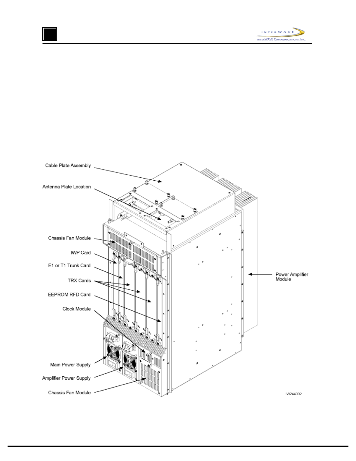
The TurboMAX consists of a chassis, one IWP card, one E1 or T1 Trunk card, two or three TRXs, an
EEPROM RFD card, one Main Power Supply module, one Amplifier Power Supply module, one Clock
module, two Fan modules, a high-power Amplifier module, and a CMA (Cable Management Assembly),
which contains combiners, diplexers, and/or filters, and which routes external cabling into the TurboMAX
chassis. Figure 1 shows the front view of a fully-loaded TurboMAX.
Figure 1. Typical Fully-Loaded TurboMAX
Application Note 16 – ve rsi on 1.1
page 2
Page 3

p
plication Note
A
3 Installation
3.1 Mounting the Chassis
1) Mount the TurboMAX chassis as you would any other interWAVE chassis, either in an equipment
rack, on a wall, or on a table, as described in the WAVEXpress BTS Installation and Commissioning
Guide.
3.2 Verifying and Configuring the E1 or T1 Card
2) When your TurboMAX is equip ped with an E1 Trunk card, ver ify that the trunk impedanc e is set
correctly on the eight-position DIP switch on the edge of the E1 card. For 75 Ohm coaxial cable,
DIP switches 1, 2, 3, 5, 6, and 7 must be set to ON, and DIP switches 4 and 8 must be set to OFF, as
indicated on the DIP switch housing. For 120 Ohm twisted pair, all the DIP switches must be set to
ON.
If you have set the E1 Trunk card for 75 Ohm coaxial cable, you may also need to ground the E1
coaxial cable shields. Note that only one side of the coaxial cables should be grounded to avoid
ground loops. To ground the Port 0 Transmit shield, place a jumper across P9 pins 1 and 2. To
ground the Port 0 Receive shield, place a jumper across P8 pins 1 and 2. To ground the Port 1
Transmit shield, place a jumper across P10 pins 1 and 2. To ground the Port 1 Receive shield, place
a jumper across P11 pins 1 and 2.
3) When your TurboMAX is equip ped with a T1 Trunk card, configure the trunk for the cable distance
to the DSX1 T1 demarcation point using the eight-position DIP switch on the edge of the T1 card.
For Port 0, use DIP switch pins 1 – 4, and for Port 1, use DIP switch pins 4 – 8.
For Port 0, when the TurboMAX is connected directly to another WAVEXpress chassis or if it is
connected to a T1 DSX1 demarcation point at 0-133ft (0-40m), set DIP switch 1 to OFF, and set
DIP switches 2, 3, and 4 to ON, as indicated on the DIP switch housing. When the TurboMAX is
connected to a T1 DSX1 demarcation point at 133-266ft (40-80m), set DIP switches 1 and 2 to OFF,
and set DIP switches 3 and 4 to ON. When the TurboMAX is connected to a T1 DSX1 demarcation
point at 266-399ft (80-120m), set DIP switches 1 and 3 to OFF, and set DIP switches 2 and 4 to ON.
When the TurboMAX is connected to a T1 DSX1 demarcation point at 399-533ft (120-160m), set
DIP switches 1, 2, and 3 to OFF, and set DIP switch 4 to ON. When the TurboMAX is connected to
a T1 DSX1 demarcation point at 533-655ft (160-200m), set DIP switches 1 and 4 to OFF, and set
DIP switches 2 and 3 to ON.
For Port 1, when the TurboMAX is connected directly to another WAVEXpress chassis or if it is
connected to a T1 DSX1 demarcation point at 0-133ft (0-40m), set DIP switch 5 to OFF, and set
DIP switches 6, 7, and 8 to ON, as indicated on the DIP switch housing. When the TurboMAX is
connected to a T1 DSX1 demarcation point at 133-266ft (40-80m), set DIP switches 5 and 6 to OFF,
and set DIP switches 7 and 8 to ON. When the TurboMAX is connected to a T1 DSX1 demarcation
point at 266-399ft (80-120m), set DIP switches 5 and 7 to OFF, and set DIP switches 6 and 8 to ON.
When the TurboMAX is connected to a T1 DSX1 demarcation point at 399-533ft (120-160m), set
DIP switches 5, 6, and 7 to OFF, and set DIP switch 8 to ON. When the TurboMAX is connected to
a T1 DSX1 demarcation point at 533-655ft (160-200m), set DIP switches 5 and 8 to OFF, and set
DIP switches 6 and 7 to ON.
Application Note 16 – ve rsi on 1.1
page 3
Page 4

p
plication Note
A
3.3 Verifying the Internal Cabling
4) Verify that the clock, antenna, and the other RF cable ends are correctly tightened to 7 to 10 in. lbs.
(79 to 113N.cm).
5) Verify the cable from the IWP card ENET connector to the external alarm terminal block on the
front of the TurboMAX chassis.
Application Note 16 – ve rsi on 1.1
page 4
Page 5

p
plication Note
A
3.4 Connecting External Cabling
6) Connect the E1 or T1 cabling directly to the E1 or T1 card using individually-shielded twisted-pair
cables, using the st andard RJ-48C pinout. The RJ-48C pinout is as follows: Pin 1 – Receive
Ring/Shield; Pin 2 – Receive Tip; Pin 4 – Transmit Ring/Shield; Pin 2 – Transmit Tip.
When you are connecting the TurboMAX directly to another TurboMAX or another piece of
equipment via an E1 or T1 port, make sure you use a crossover cable that connects the Receive leads
to the Transmit leads.
7) The TurboMAX comes in two configurations: low-power, with a single antenna, or high-power, with
up to three antennas.
When you are adding an antenna to a low-power TurboMAX, connect the antenna to the N-type
connector on the Antenna Plate Assembly on top of the TurboMAX.
When you are adding antennas to a high-power TurboMAX, make sure you connect one antenna to
each of the three N-type connectors on the Antenna Plate Assembly on top of the TurboMAX. Since
one antenna is shared by the receive paths for all TurboMAX TRXs, and since one antenna for the
transmit path for each TRX, you must connect an antenna to all available N-type antenna connectors.
8) If required by local codes, ground the TurboMAX chassis by loosening a nut inside the Cable
Management Assembly and tighteni ng t he grounding wire under the nut, per local requirements.
9) Connect any customer-defined alarm inputs to the external alarm terminal block as follows: Make
sure the external alarm inputs use normally-open relay contacts. For Alarm Input 1, connect the
alarm relay across terminal block pins 5 and 6. For Alarm Input 2, connect the alarm relay across
terminal block pins 5 and 7. For Alarm Input 3, connect the alarm relay across terminal block pins 5
and 9.
10) Connect external power to the two (Main and Amplifier) power supply units as follows:
When you connecti ng –48VDC to the two chassis power supplies, (1) set the circuit breaker on both
power supplies to OFF, and (2) connect the –48VDC leads from the power source to the terminal
blocks on the front of both power supplies. Leave the circuit breakers OFF.
When you connecting 110 through 230 VAC to the two chassis power supplies, (1) set the circuit
breaker on both power supplies to OFF, and (2) connect the AC cables from the power source to the
IEC 320 receptacles on the front of both power supplies. Leave the circuit breakers OFF.
3.5 Off-Line Commissioning
11) Turn on power to the TurboMAX chassis by setting the circuit breakers on both power supplies to
ON.
Application Note 16 – ve rsi on 1.1
page 5
Page 6

p
plication Note
A
12) Monitor the Power On Self Test (POST) by watching the front-panel LED sequence to verify proper
POST indications. Figure 2 shows the normal TurboMAX LED boot sequence. Note that the TRXs
are tested sequentially.
Power on the TurboMAX. Initial LED display is:
IIIIIIIIIIIIIIIIIIIIIIIII
P/N XXXXXX
IIIIIIIIIIIIIIIIIIIIIIIII
S/N XXXXXX
SCN
PWR
ON
LINE
FLT
RST
CON
ENET
EXT
XREF
PWR
ON/LINE
FLT
ALARMS
12
PORT 0
ALARMS
12
PORT 1
PWR
ON
LINE
FLT
SCN
PWR
ON LINE
FLT
PORT 0
PORT 1
N/A
N/A
IWP E1/T1LEDs
ON
ON
OFF
ON
N/A
ON
ON
ON
ON
ON
LED display after 30 seconds is:
SCN
PWR
ON LINE
FLT
PORT 0
PORT 1
TX
IWP code loads. LED display during download is:
LEDs
SCN
PWR
ON LINE
FLT
PORT 0
PORT 1
IWP downloads code to E1/T1 card. LED display
LEDs
RX
SCN
PWR
ON LINE
FLT
PORT 0
PORT 1
IWP E1/T1 #1LEDs
ON
ON
FLASH
OFF
N/A
N/A
IWP
ON
ON
ON
OFF
N/A
N/A
(1 minute for each card) during download is:
IWP
ON
ON
ON
OFF
N/A
N/A
N/A
E1/T1
N/A
E1/T1
N/A
ON
ON
ON
ON
ON
ON
ON
ON
ON
ON
ON
FLASH
FLASH
OFF
OFF
TRX
N/A
N/A
N/A
TRX
N/A
N/A
N/A
TRX
N/A
N/A
N/A
TRX
N/A
N/A
N/A
ON
OFF
ON
ON
OFF
ON
ON
OFF
ON
ON
OFF
ON
IWP E1 or T1
TRX
TRX code downloads from remote BSS IWP hard drive.
LEDs
SCN
PWR
ON LINE
FLT
PORT 0
PORT 1
LEDs
SCN
PWR
ON LINE
FLT
PORT 0
PORT 1
Note that the TRX FLT LED will stay illuminated until the TRX software
LED display during download is:
IWP
ON
ON
ON
OFF
N/A
N/A
BSS IWP completes TRX code download to each
card sequentially. The final LED display is:
IWP
ON
ON
ON
OFF
N/A
N/A
has been downloaded from the hard drive.
Figure 2. TurboMAX LED Sequence During the Boot Process
Application Note 16 – ve rsi on 1.1
page 6
E1/T1
N/A
E1/T1
N/A
ON
ON
OFF
OFF
OFF
ON
ON
OFF
OFF
OFF
TRX
N/A
N/A
N/A
TRX
N/A
N/A
N/A
ON
FLASH
OFF
ON
OFF
OFF
IW249001
Page 7

p
plication Note
A
13) After bootup, verify that the front-panel LEDs are lit as follows: SCN (on IWP card only) lit, PWR
lit, ON LINE on IWP and E1 or T1 cards lit, FLT not lit. Note that the ON LINE LEDs on the TRX
cards are not lit until they are unlocked by the OMC operator.
If the LED displays are different than that shown in this and the previous step, the TurboMAX has
not passed the POST. Contact Technical Support for further information.
14) Set up a Craft PC with dedicated ethernet and serial connections as shown in Figure 3 and 4,
respectively.
3Com Combo
transceiver
PCMCIA
card slot
Craft PC
RG-58 coaxial cable
BNC
T-Connector
BNC T-Connector
50 Ohm terminators
Ethernet
Port
IWP, 64MEG, MMU
HARD DISK
RST
SCN
PWR
PWR
ON
ON/LINE
LINE
FLT
FLT
ALARMS
12
CON
ENET
EXT
XREF
PORT 0
ALARMS
12
PORT 1
AUI-BNC
Transceiver
Figure 3. Connecting the Craft PC to the TurboMAX via the Ethernet Port
IW206002
Application Note 16 – ve rsi on 1.1
page 7
Page 8

p
plication Note
A
RST
IWP, 64MEG, MMU
HARD DISK
SCN
PWR
PWR
ON
ON/LINE
LINE
FLT
FLT
DB-9 port
connector
ALARMS
12
CON
ENET
PORT 0
ALARMS
12
EXT
XREF
PORT 1
DB-9 extension cable
Craft PC
computer
DB-9 port
connector
Figure 4. Connecting the Craft PC to the TurboMAX via the Serial Port
IW206001
15) Power up the Craft PC, and allow the Linux operating system to bootup.
16) Logon as ‘build’, and start XWindows by entering ‘startx’.
17) Establish serial communications with the TurboMAX by entering ‘cu –l ttyS0 –s 9600’. The
TurboMAX responds with ‘Connected’. Press the [ENTER] key to display the ‘bts:A->’ prompt.
Application Note 16 – ve rsi on 1.1
page 8
Page 9

p
plication Note
A
18) Verify the boot parameters by entering ‘bootChange’. A list of parameters appears as you press the
[ENTER] ke y, a s shown in Figure 5.
’.’ = clear field; ’-’ = go to previous field; ^D = quit
boot device : qu
processor number : 0
host name : craftpc
file name : /home/target/vxWorks
inet on ethernet (e) : 172.16.80.42:fffff000
inet on backplane (b):
host inet (h) : 172.16.80.43
gateway inet (g) :
user (u) : target
ftp password (pw) (blank = use rsh):
flags (f) : 0xa
target name (tn) : bts
startup script (s) : /home/target/iwvstart
other (o) :
Figure 5. Verifying/Changing TurboMAX Boot Parameters
Make sure the parameters include the listed values. If so, continue with the next step. If not, reenter
‘bootChange’, press the [ENTER] key to display the desired line, press period ‘.’ to delete the
incorrect entry, type in the correct entry, and press the [ENTER] key to continue with the next
parameter. When all the bootChange parameters display the correct values, continue with the next
step.
19) Reboot the TurboMAX by pressing the [CTRL][x] key combination. Verify the current software
version and patch level by pressing [RETURN] to display the ‘bts:A->’ prompt. Then enter
‘iwversion’. The TurboMAX responds with the BSX code version, the software release, the
encryption status, and the patches currently installed. Verify that you have the software version
iw05_00.132 or later installed.
20) Verify the images loaded in the TurboMAX IWP flash version by entering ‘printConfigBlocks’. The
resulting parameters display the Primary Config Block imageCurrent and Secondary Config Block
imageCurrent entries in the form ‘iwXX_YY.ZZZ’, which indicates the IWP flash version. Contact
Technical Support to ensure you have IWP flash version iw05_00.132 or later installed.
21) Run the E1 or T1 POST diagnostics by disconnecting all E1 and T1 lines from the TurboMAX,
entering ‘reboot’ at the ‘bts:A->’ prompt. Verify that the resulting seven sequential tests appear as
‘PASSED’. If the E1 or T1 Trunk card fails any of these t ests, the E1 or T1 card is defective; ret urn
the E1 or T1 card to interWAVE, and redo this test with the replacement E1 or T1 Trunk card.
22) Terminate any existing telnet and/or rlogin session by logging in as root (bts:A-> su – root), clearing
existing sessions (# /sbin/arp –d iwbox), and logging out of root (# exit).
Application Note 16 – ve rsi on 1.1
page 9
Page 10

p
plication Note
A
23) Verify telnet communications with the IWP card by terminating the serial connection by entering
‘~.’ (tilde .), which returns the prompt to ‘build@craftpc:~>’.
After the serial connection is terminated, enter ‘telnet bts’ to display the ‘bts:A->’ prompt. This
shows that you are able to set up a telnet session with the TurboMAX.
Terminate the telnet session by entering ‘logout’. This causes the TurboMAX to display ‘Connection
closed by for eign host’ and the prompt changes back to ‘build@craftpc:~>’.
24) Reestablish a serial connection with the TurboMAX by entering ‘cu –l ttyS0 –s 9600’. The
TurboMAX responds with ‘Connected’. Press the [ENTER] key to display the ‘bts:A->’ prompt.
25) At the ‘bts:A->’ prompt, enter ‘runtrxpost’ to test the TRX card(s). The resulting output contains the
output for the various TRX tests, including one line for each TRX that reads: ‘TRX CARD IN SLOT
<2, 4, or 6>: COMPLETED TRX POST OFFLINE TEST: <PASSED/FAILED>’.
26) Review the E1/T1 and BTS POST test results by entering ‘postReportE1Trx’. The TurboMAX
displays a summary of the E1/T1 and TRX test results, which should all appear as ‘PASSED’ except
those which appear as ‘NOT-RUN’.
27) Reboot the TurboMAX after running the POST t ests by entering ‘reboot’ at the ‘bts:A->’ prompt.
28) Have the E1 or T1 link provider certify that the links pass a BER (Bit Error Rate or Bit Error Ratio)
test at 10
29) Reconnect all E1 or T1 cables disconnected to run the POST tests.
-8
or better over 20 minutes.
3.6 Performing Racal Tests
30) Perform the Racal Test procedures for the TurboMAX as described in the interWAVE Field
Maintenance Guide for the 16W TurboWAVE. The only difference is that the output power of the
TurboMAX is slightly higher.
3.7 Off-Line Commissioning of a TurboMAX Daisy Chain
This is an optional section, and is only required if multiple TurboMAXs are to be daisy-chained off of a
BSC, BS Plus, or NIB. If this configuration is used, each TurboMAX must be installed separately, and must
have off-line commissioning procedures independently performed. Once each TurboMAX is installed and
commissioned, the TurboMAXs can be daisy chained together.
31) Before connecting any TurboMAXs, ensure that they are all installed and off-line commissioned.
32) Ensure that all the TurboMAXs have been tested using the Racal Test Set.
33) Ensure that a different Abis link has been set for each TurboMAX using the Abis Manager time slot
has been set for each TurboMAX as follows:
After each TurboMAX has been Racal tested, enter ‘getFlashE1Chan’ at the Craft PC ‘bts:A->’
prompt. The TurboMAX displays the timeslot reserved for the LAPD signaling timeslot (default =
16).
To change this value, enter ‘setFlashE1Chan <timeslot>’ at the Craft PC ‘bts:A->’ prompt,
where<number> is any unassigned E1 or T1 timeslot between 1 and 31, or between 1 and 24,
respectively.
Note that interWAVE recommends the following Abis timeslot assignments: First TurboMAX in the
daisy chain, Abis timeslot = 16. Second TurboMAX in the daisy chain, Abis timeslot = 17. Third
Application Note 16 – ve rsi on 1.1
page 10
Page 11

p
plication Note
A
TurboMAX in the daisy chain, Abis timeslot = 18. Fourth TurboMAX in the daisy chain, Abis
timeslot = 19.
Verify that the Abis timeslot has been changed correctly. Enter ‘getFlashE1Chan’ at the ‘bts:A->’
prompt. The TurboMAX displays the timeslot reserved for the LAPD signaling timeslot.
34) Reboot each TurboMAX by entering ‘reboot’ at the ‘bts:A->’ prompt.
35) After all TurboMAXs in a daisy chain have been assigned unique Abis LAPD links, connect them to
each other and to the associated BSC, BS Plus, or NIB with E1 or T1 links as described in Section
3.4.
3.8 Shutting Down the Craft PC and Disconnecting the Serial and
Ethernet Connections
36) Terminate the serial connection with the TurboMAX by entering ‘~.’ (tilde .), which returns the
prompt to ‘build@craftpc:~>’.
37) Exit the XWindows session by pressing [CTRL][ALT] and [BACKSPACE] simultaneously. At the
‘build@craftpc:~>”’ prompt, enter ‘exit’.
38) At the ‘craftpc login:’ prompt enter ‘root’ to display the ‘craftpc:~#’ prompt.
39) Shut down the Craft PC operating system by entering ‘shutdown –h now’. After about one minute,
the Craft PC displays ‘System halted’ and ‘INIT: No more processes left in runlevel 0’.
40) Turn off the Craft PC by toggling the power switch. The serial and ethernet connections can now be
removed between the Craft PC and the TurboMAX.
41) Inform the OMC operator that the TurboMAX is ready for on-line commissioning.
3.9 On-Line Commissioning
On-line commissioning of the TurboMAX requires that an on-site field engineer work with the OMC
operator, after installation and off-line commissioning.
42) Verify that the TurboMAX is fully commissioned, that it is connected to a BSC, BS Plus, or NIB
network element, and that the OMC is communicating with the connected network element.
43) Have the operator verify that the RF frequencies are cleared to transmit.
44) Have the OMC operator download the Tur boMAX configuring and correc t software version a nd
operational parameters as defined in the WAVEView OMC Operations and Maintenance Guide and
the interWAVE Network Implemetation Manual.
45) Have the OMC operator perform the following:
Create a planned cell in the OMC database corresponding to this TurboMAX. The planned cell
should at minimum include the Cell ID and LAC for the TurboMAX.
Define neighbor relationships for the planned cell.
Create a managed cell from the planned cell.
Set the TurboMAX parameters, including its base station identity code.
Set the TurboMAX Abis parameters, including the corresponding E1 or T1 card slot and Abis
LAPD link.
Application Note 16 – ve rsi on 1.1
page 11
Page 12

p
plication Note
A
Define the TurboMAX beacon TRX, and assigning ARFCN for each TRX.
When the TurboMAX is daisy chained, setting the ‘E1 use type’, ‘Previous TurboMAX node’, and
‘Next TurboMAX node’ in the TurboMAX Manager View, and setting the ‘E1 Chan’ as the Abis
channel in the Abis Manager View as described in the WAVEView OMC Operations and
Maintenance Guide.
The rest of the TurboMAX on-line commissioning requires that an on-site field engineer work with the
OMC operator as shown in Figure 6.
Procedures for OMC Operator
Unlock the Abis
interface
Unlock the
TurboMAX and
RCARRIER
Check state of
TurboMAX
Unlock the
TurboMAX
OMC
Lock E1 or T1
Ports
Verify Database
Open TurboMAX
alarm and event
list views
Check state of
TurboMAX
Check state of
TurboMAX
Check alarm and
event detailed
views
Check for
cleared events
and alarm in all
views
Procedures for TurboMAX
Field Engineer
Step 46
Provide
TurboMAX
information
Step 47
Turn
TurboMAX
power OFF
Step 48
Turn TurboMAX
power ON
Step 51
Disconnect E1
or T1 cables
Step 52
Reconnect E1
or T1 cables
BSS
Check for
TurboMAX state
Verify external
alarms
Verify TRX
timeslots
Lock the
TurboMAX
Figure 6. On-Line Commissioning Procedures
Application Note 16 – ve rsi on 1.1
Step 53
Test external
alarms
Step 54
Use mobile to
verify timeslots
IW249002
page 12
Page 13

p
plication Note
A
46) Provide the OMC operator with all part, revision, and serial numbers for the TurboMAX cards and
modules.
47) Power down the TurboMAX by setting the Main and Amplifier Power Supply module switches to
OFF. Have the OMC operator verify the changed state of the TurboMAX.
48) Power on the TurboMAX by setting the Main and Amplifier Power Supply module switches to ON.
Have the OMC operator verify the changed state of the TurboMAX.
49) Have the OMC operator lock the E1 or T1 ports, and verify that TurboMAX alarms clear.
50) Have the OMC operator unlock the E1 or T1 ports carrying the OAM link, and verify the state of the
TurboMAX.
51) Label and remove the E1 or T1 cables from the TurboMAX. Have the OMC operator monitor the
OAM link and confirm it is ‘disconnected’.
52) Reconnect the E1 or T1 cables to the TurboMAX. Have the OMC operator verify that the OAM link
is restored.
53) Test external alarms as follows:
Whether or not the external alarms are to be used, short pins 5 and 6 on the TurboMAX external
alarm input terminal block. Have the OMC operator verify that after a delay, the first customerdefined alarm shows an alarm event.
Remove the short between pins 5 and 6 on the TurboMAX external alarm input terminal block. Have
the OMC operator verify that after a delay, the first customer-defined alarm event clears.
54) Refer to the debug mobile documentation for operating procedures. Use the debug mobile to debug
mode, and ensure that the debug mobile displays that the timeslot being used corresponds to the
timeslot that was unlocked by the OMC operator. Place a mobile-to-mobile call using the debug
mobile and the TRX under test, and verify that a two-way call can be made on this timeslot with
good audio quality, power, and low interference. End the call.
This test checks the performance of each timeslot contained within each TurboMAX TRX.
Sequentially perform the same test on all TCH timeslots as outlined in Table 1 or Table 2. No te that
the number of timeslots to be tested are different for a two TRX TurboMAX and a three TRX
TurboMAX.
Application Note 16 – ve rsi on 1.1
page 13
Page 14

p
plication Note
A
Table 1. Testing Timeslots in a Two-TRX TurboMAX
TRX Number Timeslot Number Channel Type Testing Necessary
First TRX (Note)
Second TRX (Note)
Note: The BCCH can be assigned to any TRX in the TurboMAX. The label ‘First TRX’
applies to the TRX to which the BCCH is assigned. The OMC operator determines which
physical TRX is ‘First’ or ‘Second’.
0 BCCH No
1 SDCCH No
2TCHYes
3TCHYes
4TCHYes
5TCHYes
6TCHYes
7TCHYes
0TCHYes
1TCHYes
2TCHYes
3TCHYes
4TCHYes
5TCHYes
6TCHYes
7TCHYes
Table 2. Testing Timeslots in a Three-TRX TurboMAX
TRX Number Timeslot Number Channel Type Testing Necessary
First TRX (Note)
0 BCCH No
1 SDCCH No
2TCHYes
3TCHYes
4TCHYes
5TCHYes
6TCHYes
7TCHYes
Application Note 16 – ve rsi on 1.1
page 14
Page 15

p
plication Note
A
Table 2. Testing Timeslots in a Three-TRX TurboMAX (continued)
Second TRX (Note)
Third TRX (Note)
Note: The BCCH can be assigned to any TRX in the TurboMAX. The label ‘First TRX’
applies to the TRX to which the BCCH is assigned. The OMC operator determines which
physical TRX is ‘First’, ‘Second’, or ‘Third’.
0TCHYes
1TCHYes
2TCHYes
3TCHYes
4TCHYes
5TCHYes
6TCHYes
7TCHYes
0TCHYes
1TCHYes
2TCHYes
3TCHYes
4TCHYes
5TCHYes
6TCHYes
7TCHYes
Troubleshooting
Other than the POST testing done in Section 3.5, the TurboMAX TRXs, EEPROM RFD card, high-power
Amplifier module, and CMA (Cable Management Assembly) combiners, diplexers, and/or filters are
replaced as a unit. Contact Technical Support for detailed troubleshooting information.
Application Note 16 – ve rsi on 1.1
page 15
 Loading...