

Page 1
HiGain
HiGain
HiGain
HDSL2
H
2
T
U
•
3
8
8
SETUP
MODE SEL
USER MANUAL
L
1
H2TU-C-388 List 1 Line Unit
Part Number: 150-2406-01
CLEI: VACHKW0C
STATUS
RS
232
DCE
Page 2

152-388-100-02, Issue 2
Revision History of This Manual
Revision Release Date Revision s Ma de
01 June 6, 2000 Initial release.
02 Jaunary 18, 2002 ADC rebranding
Copyright
Jaunary 18, 2002
© 2002 ADC DSL Systems, Inc. All rights reserved.
Trademark Information
ADC is a registered trademark of ADC Telecommunications, Inc. HiGain is a registered trademark of ADC DSL Systems, Inc.
No right, license, or interest to such trademarks is granted hereunder, and you agree that no such right, license, or interest
shall be asserted by you with respect to such trademark. Other product names mentioned in this practice are used for
identification purposes only and may be trademarks or regi stered trademarks of their respect ive companies.
Disclaimer of Liability
Information containe d in this documen t is company private to ADC DSL Systems, Inc., and shal l not be modified , used, copied ,
reproduced or discl osed in whole or in part without the wr itten consent of AD C.
Contents herein are current as o f th e da te of publication. ADC reserves the right to c h an ge th e con te nts wi thout prio r no tic e .
In no event shall ADC be liable for any damages resulting from loss of data, loss of use, or loss of profits, and ADC further
disclaims any and all liability for indirect, incidental, special, consequential or other similar damages. This disclaimer of
liability applies to all products, publications and services during and after the warranty period.
ii June 6, 2000 H2TU-C-388 List 1
Page 3
152-388-100-02, Issue 2 Using This Manual
USING THIS MANUAL
The following conventions are used in this manual:
• Monospace type indicates screen text.
• Keys you press are indicated by small icons such as or . Key combinations to be pressed
simultaneously are indicated with a plus sign as follows: + .
Y ENTER
CTRL ESC
• Items you select are in bold.
• Three types of messages, identified by icons, appear in text.
Notes contain information about special circumstances.
Cautions indicate the possibility of personal injury or equipment damage.
The Electrostatic Discharge (ESD) symbol indicate s that a device or as sembly is susc eptible to
damage from electrostatic discharge.
For a list of abbreviations used in this document, refer to “Appendix E - Abbreviations” on page 55.
INSPECTING SHIPMENT
Upon receipt of the equipment:
• Unpack each container and inspect the contents for signs of damage. If the equipment has been damaged in
transit, immediately report the extent of damage to the transportation company and to ADC DSL Systems,
Inc. Order replacement equipment, if necessary.
• Check the packing list to ensure complete and accu rate shipmen t of each listed item. If the shipment is short
or irregular, contact ADC DSL Systems, Inc. as described in “Appen dix D - Product Suppo rt” on page 54. If
you must store the equipment for a prolonged period, store the equipment in its original container.
H2TU-C-388 List 1 June 6, 2000 iii
Page 4

Inspecting Shipment 152-388-100-02, Issue 2
iv June 6, 2000 H2TU-C-388 List 1
Page 5

152-388-100-02, Issue 2 Table of Contents
TABLE OF CONTENTS
Overview ____________________________________________________________________________ 1
Features..............................................................................................................................................1
Compatibility .....................................................................................................................................2
Applications.......................................................................................................................................2
Front Panel __________________________________________________________________________ 3
Installation___________________________________________________________________________ 7
Verification ........................................................................................................................................8
Verification without a Downstream Device........................................................................8
Verification with a Downstream Device.............................................................................8
Provisioning__________________________________________________________________________ 9
Using the MODE and SEL Buttons...................................................................................................9
Setting Options through MODE and SEL...........................................................................9
Resetting to Factory Default Values..................................................................................10
Displaying System Parameter Settings..............................................................................10
Loopback Modes ...............................................................................................................10
Using a Maintenance Terminal........................................................................................................10
Connecting to a Maintenance Terminal.............................................................................10
The Logon Screen..............................................................................................................11
Provisioning Tasks......................................... ............................................. .....................................13
Setting Date and Time.......................................................................................................13
Setting Circuit ID Numbers...............................................................................................14
Configuring the System.....................................................................................................15
Clearing the History, Alarm, and Event Log Screens .......................................................21
Monitoring System Activity and Performance ____________________________________________ 22
Using the Monitor Screen to View System Activity........................................................................22
Using the Performance Screens to View Performance Data............................................................24
Performance History at the DS1 Interface.........................................................................24
Performance History at the HDSL2 Interface...................................................................28
Using the Performance Screens to View Alarm Data......................................................................30
Alarm History at the DS1 Interface...................................................................................31
Alarm History at the HDSL2 Interface..............................................................................33
Using the Event Log to Track System Events.................................................................................34
H2TU-C-388 List 1 June 6, 2000 v
Page 6

Table of Contents 152-388-100-02, Issue 2
Testing _____________________________________________________________________________ 36
Front-Panel System Alarms............................................................................................................. 36
Alarm Option for DLC Feed............................................................................................. 37
Retiring System Alarms.................................................................................................... 37
Remote LOS and AIS Response....................................................................................... 38
OCT55 Test Pattern with AMI Line Code...................................................................................... 38
Loopback Operation........................................................................................................................ 39
Generic Loopback Commands.......................................................................................... 39
Special Loopback Commands........................................................................................... 41
Manual Loopback Session................................................................................................42
Loopback Test Procedures ..............................................................................................................43
General Troubleshooting Tips .......................................................................................... 43
GNLB Test Procedures................. ...... ............................................. ...... ........................... 43
A1LB, A2LB, and A5LB Test Procedures....................................................................... 45
A3LB and A4LB Test Procedures....................................................................................47
Appendix A - Specifications____________________________________________________________ 48
Power Consumption ...................................................................... .................................................. 49
Maximum Power Dissipation.......................................................................................................... 49
Maximum Current Drain................................................................................................................. 49
Loop Attenuation.................................................................................................. ........................... 50
HiGain Line Unit Card-Edge Connector.........................................................................................50
Network Management Control Bus.................................................................................. 50
Fuse Alarm........................................................................................................................51
Craft Port......................................................................................................................................... 51
Appendix B - Functional Operation _____________________________________________________ 52
Timing ............................................................................................................................................. 52
Ground Fault Detect........................................................................................................................ 52
Appendix C - Compatibility____________________________________ ________________________ 53
Appendix D - Product Support _________________________________________________________ 54
Appendix E - Abbreviations____________________________________________________________55
Certification and Warranty _____________________________________________ Inside Back Cover
vi June 6, 2000 H2TU-C-388 List 1
Page 7

152-388-100-02, Issue 2 List of Figures
LIST OF FIGURES
1. H2TU-C-388 List 1 Front Panel....................................................................................................................3
2. Installing the H2TU-C-388 into a Shelf........................................................................................................7
3. Logon Screen ...............................................................................................................................................12
4. Configuration Menu - Date and Time.........................................................................................................13
5. Inventory Menu ............................. ............................................. .................................................................14
6. Configuration Menu ....................................................................................................................................15
7. Configuration Menu - Standard Options (Defaults Shown)........................................................................16
8. Configuration Menu - ADC Options (Defaults Shown)..............................................................................16
9. Configuration Menu - Reset to Factory Defaults........................................................................................20
10. Master Clear ................................................................................................................................................21
11. Monitor Screen - Active Loopback with Alarms........................................................................................22
12. H2TU-R DS1 31-Day Performance History...............................................................................................24
13. H2TU-R DS1 48-Hour Performance History..............................................................................................25
14. H2TU-C DS1 25-Hour Performance History..............................................................................................25
15. H2TU-R DS1 Current Statistics..................................................................................................................26
16. H2TU-C DS1 Current Statistics..................................................................................................................26
17. H2TU-C HDSL2 31-Day Performance History..........................................................................................28
18. H2TU-C HDSL2 48-Hour Performance History.........................................................................................28
19. H2TU-C HDSL2 25-Hour Performance History.........................................................................................29
20. H2TU-C HDSL2 Current Statistics.............................................................................................................29
21. H2TU-C DS1 Alarm History Screen...........................................................................................................31
22. H2TU-R DS1 Alarm History Screen...........................................................................................................31
23. H2TU-C HDSL2 Alarm History Screen .....................................................................................................33
24. System Event Log........................................................................................................................................34
25. H2TU-R LOS and AIS Response Priorities................................................................................................38
26. Loopback Summary.....................................................................................................................................39
27. Loopback Modes.........................................................................................................................................44
28. HiGain Line Unit Card-Edge Connector.....................................................................................................50
29. 210-to-DB-9 Adapter...................................................................................................................................51
30. H2TU-C-388 List 1 Block Diagram............................................................................................................52
H2TU-C-388 List 1 June 6, 2000 vii
Page 8

List of Tables 152-388-100-02, Issue 2
LIST OF TABLES
1. Front-Panel Description................................................................................................................................ 4
2. Front-Panel Display Messages...................................................................................................................... 5
3. Navigational Keys for the HiGain Maintenance Terminal Screens............................................................11
4. Logon Screen Menus .................................................................................................................................. 12
5. HiGain Line Unit List 1 Standard Config Screen Options ......................................................................... 17
6. HiGain Line Unit List 1 ADC Config Screen Options...............................................................................18
7. DS1/DSX-1 24-hour PM Threshold ...........................................................................................................20
8. Monitor Screen Descriptions ...................................................................................................................... 23
9. Acronyms Used on the DS1 Performance History Screens........................................................................ 27
10. Acronyms Used on the HDSL2 Performance History Screens................................................................... 30
11. DS1 Alarm Descriptions............................................................................................................................. 32
12. HDSL2 Alarm Descriptions........................................................................................................................33
13. Event Log Entry Messages List.................................................................................................................. 35
14. Front-Panel System Alarms Summary.......................................................................................................36
15. Summary of HiGain Loopback Codes and Activation Methods ................................................................ 40
16. Addressable Repeater Loopback Commands (A1LB, A2LB, A5LB)........................................................ 45
17. Addressable Repeater Loopback Commands (A3LB and A4LB).............................................................. 47
18. H2TU-C-388 Power Parameters.................................................... ...... ....................................................... 49
19. HDSL2 Cable Attenuation Chart................................................................................................................ 50
viii June 6, 2000 H2TU-C-388 List 1
Page 9

152-388-100-02, Issue 2 Overview
OVERVIEW
The HiGain® product family from ADC® is the industry’s first practical implementations of High- bit-rate Digital
Subscriber Line 2 (HDSL2). ADC products are fully compliant with the HDSL2 standard. Providing full-rate T1
access using just a single copper pair, HDSL2 is a cost-effective so lution that offers an open architecture. The open
architecture inherent in HDSL2 guarantees interoperability, allowing simple and economic accommodation of
network growth. HiGain uses t he industry’s first HDSL2 chipset (ANSI T1/E1.4 compliant) developed by ADC.
HiGain HDSL2 products provide 1.552 Mbps transmission on one unconditioned copper pair over the full Carrier
Service Area (CSA) range. The CSA includes loops up to 12,000 feet of 24 American Wire Gauge (AWG) wire
or 9,000 fee t of 26 AWG wire, includi ng bridged t aps.
FEATURES
The HiGain Line Unit line unit is the Central Office (CO) side of a T1 transmission system.
• HDSL2 transmission features
– Lightning and power cross-protection on HDSL2 interfaces
– Full duplex HDSL2 transmission on one pair at 1.552 Mbps
– Ultra-low wander (Stratum 1 compliant)
– Grounded loop detection on High bit-rate Digital Subscriber Line 2 (HDSL2)
• Front-panel provisioning features
– Four-character status display
– Status Light Emitting Diodes (LEDs)
– Bantam 210 jack port for RS-232 connection to a maintenance terminal
– MODE and SEL switches
• HiGain HDSL2 maintenance screens for inventory, provisioning, and troubleshooting
– DS1 and HDSL2 performance monitoring
– Non-volatile alarm histories
• Configuration options
– Selectable DS1 pre-equalizer
– Bipolar Violation Transparency (BPVT) options
– Bit Error Rate (BER) alarm
– Loss of Signal/Alarm Indicator Signal (LOS/AIS) payload alarm option
– Remote provisioning
– Selectable loopback activation codes
• Compatible with Double Dual Module Plus (DDM+) high-density shelves
• Payload (PL) and HiGain Generic (HG) loopback source identification
• Network Ma nagement and Administration (N MA) interface
• Margin Alarm (MAL) alarm
H2TU-C-388 List 1 June 6, 2000 1
Page 10

Overview 152-388-100-02, Issue 2
DS1 is used throughout this document to refer to either the remote unit’s DS1 interface or the
line unit’s DSX-1 interface.
COMPATIBILITY
The H2TU-C-388 List 1 is designed to mo unt in DDM+ high-density shelves. For a list of compatible shelves see
“Appendix C - Compatibility” on pag e 53.
APPLICATIONS
HiGain systems provide a cost-effective, easy-to-deploy method for deliv ering DS1 High Capacity Digital Service
(HCDS) over a single copper pair. HiGain systems support a multitude of network connections and system
models.
• The service is deployed over one unconditioned, non-loaded copper pair.
• With HiGain, conventional, inline DS1 repeaters are no longer required.
• Cable pair conditioning, pair separation, and bridged tap removal are not re quir ed.
Each loop has no more than 35 dB of loss at 196 kHz, with driving and terminating impedances of 135
general, HiGain systems:
• Operate effectively in the same cable binder group with other HDSL2 lines, HDSL, DS1, ADSL, SDSL,
POTS, Digital Data Service (DDS), and other transmission schemes.
• Can be used with customers requiring DS1 service on a temporary or permanent basis.
• Provide a means of quickly deploying service in advance of fiber optic transmission systems.
Ω. In
2 June 6, 200 0 H2TU-C-388 Li st 1
Page 11
152-388-100-02, Issue 2 Front Panel
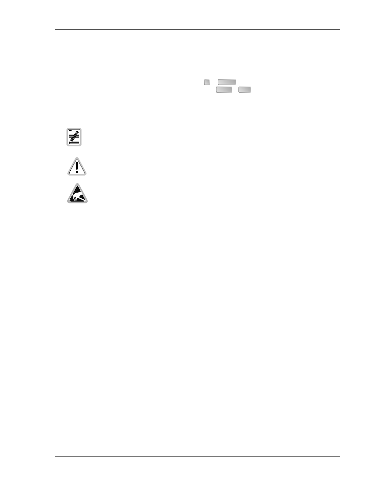
FRONT PANEL
Figure 1 shows the H2TU-C-388 List 1 fron t panel. Tabl e 1 on page 4 describes the front-panel comp onents. For
a list of front-panel display messages, refer to Table 2 on page 5. For pinout diagrams of the H2TU-C card-edge
connector and craft port, refer to “Appendix A - Specifications” on page 48 .
HiGain
HDSL2
L
1
Front-panel display
MODE and SEL
system option buttons
H
2
T
U
•
C
3
8
8
SETUP
MODE SEL
STATUS
Craft port
RS
232
DCE
Figure 1. H2TU-C-388 List 1 Front Panel
List number
CLEI and ECI
barcode label
Status LED
Configuration number
H2TU-C-388 List 1 June 6, 2000 3
Page 12

Front Panel 152-388-100-02, Issue 2
Table 1. Front-Panel Description
Front-Panel Feature Function
Front-panel displ a y Displays four-character status, provisioning, and alarm system messages. The front-panel display
illuminates when power is initially applied. To conserve power the display only remains on for
5 minutes. Using the MODE or SEL buttons reactivates the display and restarts the 5-minute timer.
Refer to Table 2 on page 5 for a listing of t he f our-character messages.
MODE and SEL system option
buttons
Permits user options to be monitored and modified without the need of a main tenance terminal.
Used to initiate all HiGain loopbacks and to disp lay DSX-1 line parameters and line unit identity.
Status LED The status LED can repor t the following cond itions:
Off Line power is off.
Green Normal operation.
Red Fuse alarm.
Flashing red HDSL2 acquisition or system alarm.
Yellow An H2TU-C-388 List 1 Customer Remote Loopback (CREM) or a Network Local Loopback (NLOC)
is in effect.
Flashing yellow H2TU-C-388 List 1 is in an Armed (ARM) state.
Craft port (RS-232) Provides bidirectional communication between the unit and an external te rminal to allow
configuratio n and performance monitoring through the Maintenance Terminal sc re e ns .
CLEI and ECI bar code label Provide s the hu ma n -r e ad a ble Com m on La ng ua ge Eq uipment Identifier (CLEI) code number and
the Equipment Ca talog Item (ECI) bar code number.
List number Identifies the list number of the H2TU-C-388 List 1.
Configuration Number For some products the configuration number may cont ain either a standalone two or t hree-digit
configuration number or a five- or six-digit warranty configur ation number as follows:
Digit 1 - Last digit of shipment year
Digits 2 and 3 - Shipment month
Digits 4, 5, and 6 - Configuration number
The configuration number identifies the version of the product. New configuration numbers usually
accompany changes in the last two characters of the CLEI code.
The configuration number is found on a small label attached to the unit. It is the last two numbers
(following the x) of a 13-character pa rt n umber. For example: 150-1234-01-x01.
4 June 6, 200 0 H2TU-C-388 Li st 1
Page 13

152-388-100-02, Issue 2 Front Panel
Table 2 lists the front-panel display messages. The four-character display reports the code of an alarm, loop back,
or diagnostic message and, in some cases, is followed by a second four-character message that modifies the first
message with a value or current configuration setting.
Table 2. Front-Panel Display Messages
Message Full Name Description
SYSTEM ALARM MESSAGES
ACO Alarm Cutoff A system alarm has occurred and has been retired to an ACO condition
ALRM Alarm Condition Exists A system alarm condition is in effect.
DBER DS1 Bit Error Rate A system DS1 BER alarm is in effect and remains in effect until cleared.
HBER HDSL2 Block Error Rate A system HDSL2 Block Error Rate al arm is in effect.
LA Loop Attenuation Indicates that the attenuation on the HDSL2 loo p has exceeded the
LAIS Local Alarm Indication Signal Indicates an AIS (all ones) pattern is being transmitted from th e local
LLOS Local Loss of Sig na l Indicates that no signal is detected at th e DSX-1 input to the H2TU-C.
LOSW Loss of Sync Word Indicates that the HDSL2 loop has lost synchronization.
LRAI Line RAI Indicates an RAI alarm (yellow) from the CPE with an error-free signal
MAL Margin Alarm The margin on HDSL2 loop has dropped below the threshold (0 to 15
PWR FEED GND Ground The HDSL2 loop is grounded.
PWR FEED OPEN Open Indicates a line power open condition.
PWR FEED SHRT Short Indicates a short between th e Tip and Ring of the HDSL2 pair.
PRMF Perfor mance Report Messaging -
Far End
PRMN Performance Report Messag ing -
Near End
RAIS Remote Alarm Indication Signal Indicates an AIS (all o nes) pattern is being trans mitted from the re mote
RLOS Remote Loss of Signal Indicates that no signal is detected at the DS1 input to the H2TU-R.
RRAI Remote RAI Indicates an RAI alarm (yellow) from th e CPE with errors from the line
TUC Tran smission Unit Central Off ice Accompanies the HBER, MAL, and LA alarm and indicates that the alarm
TUR Transmission Unit Remote End Accompanies the HBER, MAL, and LA alarm and indicates that the alarm
by pressing the SEL butto n on the H2T U-C front panel.
maximum threshold value.
DS1 output port.
Causes a system alarm.
from the line unit or network.
dB) as set by the operator.
H2TU-R PRM-FE BER threshold ha s been exceeded.
H2TU-R PRM-NE BER threshold has been ex ceeded.
DS1 output port.
Causes a system alarm.
unit or network.
has occurred at the H2TU-C central office unit.
has occurred at the H2TU-R remote unit.
LOOPBACK MESSAGES
CLOC Customer Local Loopback Signal from customer is looped back to the customer at the H2TU-R.
COLB Central Office Loopback Dual loopback at the H2TU-C.
CREM Customer Remote Loopback Signal from customer is looped back to th e customer at the H2TU-C.
NLOC Network Local Loopback DSX-1 signal is looped back to the network at the H2TU-C.
NREM Network Remote Loopback DSX-1 signal is looped back to the network at the H2TU-R.
RULB Remote Unit Loopback Dual loopback at the H2TU-R.
Continued
H2TU-C-388 List 1 June 6, 2000 5
Page 14

Front Panel 152-388-100-02, Issue 2
Table 2. Front-Panel Display Messages (Continued)
Message Full Name Description
SMJK Remote SmartJack Loopb ack DSX-1 signal is looped back to the network at the H2TU-R SmartJack
DIAGNOSTIC MESSAGES
A = xx Maximum Loop Attenuation The Attenuation (A) message appears followed by xx, where xx is the
ACQ Acquisition The multiplexers of the H2TU-C and H2TU-R are trying to estab li sh
AnL Acquisition n Loop The multiplexers of the two devices are trying to establish
ARM HiGain System Armed Armed to respond to Intelligent Repeater Loop (ILR) codes.
BAD RT? No Response from H2TU-R The H2TU-C receives no response from the H2TU-R and all HDSL2 loop
FERR Framing Bit Error Occurred Framing bit error occurred at H2TU-C DSX-1 input.
FLDL Flash Download Flash download of firmware updates. Contact Customer Service for
HES HDSL2 CRC Error H2TU-C HDSL2 Loop Cyclical Redundancy Check (CRC) error.
LBPV Local Bipolar Violation A bipolar violation has bee n received at the DSX-1 input to the HiGain
M=xx HDSL2 Loop Margi n Indicates the power of the received HDSL2 signal relative to noise (S/N
MNGD Managed The HiGain Line Unit is under control of the HMU-319 Network
PWR FEED OFF Power Feed Off HDSL2 span power has been turned off by setting the PWRF option to
PWR FEED ON Power Feed On Indicates that the HDSL2 loop is not grounded or shorted.
SIG Signaling The transceivers of the H2TU -C and H2TU-R are trying to establi sh
SnL Signal n Loop The transceivers of the two devices are trying to establish contact with
module.
loop attenuatio n, measured in dB.
synchronization over the HDSL2 loop.
synchronization with each ot her, where n is the number of the span.
conditions are norm al. Therefore, the integri ty of the H2TU-R or the
HDSL2 loop is quest ionable.
update procedures (see “Appendi x D - Product Support” on page 5 4).
Line Unit.
with respect to 21.5 dB). Any value of 6 dB or greater is adequate for
reliable system operation.
management unit. In this state, the front-panel craft port and push
buttons are disabled.
off, or HDSL2 span power has been turned off by use of the A2LB
Intelligent Office Repeater (IOR) Power Down co de.
contact with each other over the HD SL2 loop.
each other, where n is the number of the span.
SYSTEM INFORMATION MESSAGES
(a)
CODE xxxx L ine Code: AMI or B8ZS The line code that H2TU-C-388 is receiving at its DSX-1 interface, if the
DS1 option is set to AUTO. Otherwise, it mimics either of the other two
DS1 line code settings, Alternate Mark Inversion (AMI) or Bipolar with
8-Zero Substitution (B8ZS).
FRM xxxx Frame: SF, ESF, UNFR Defines the type of frame pattern being received from the DSX-1:
SuperFrame (SF), Extended SuperFrame (ESF), Unframed (UNFR).
LATT xx Loop Attenuation The current loop a tt enuation threshold setting measured in dB.
LIST xx HiGain Line Unit List Number The list number xx.
MARG xx Margin The current margin threshold setting measured in dB.
VER x.xx HiGain Line Unit Software Version
The software version number (x.xx).
Number
(a) System information messages are displayed in scroll mode. To scroll through system information messages, press the MODE
button for 3 or more seconds.
6 June 6, 200 0 H2TU-C-388 Li st 1
Page 15
152-388-100-02, Issue 2 Installation
INSTALLATION
Upon receipt of the equipment, insp ect the contents for signs of damage. If the equipm ent h as
been damaged in transit, immediately report the extent of damage to the transportation
company and to ADC.
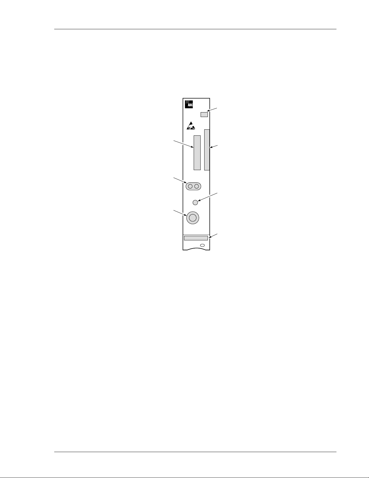
Figure 2. Installing the H2TU-C-388 into a Shelf
When installing an H2TU-C in a chassis, be sure to wear an antistatic wrist strap. Avoid touching
components on the circuit board.
To comply with the intrabuilding wiring requirements of GR-1089 CORE, Section 4.5.9, the
shields of the ABAM-type cables that connect the H2TU-C-3 88 Lis t 1 DSX-1 output ports to the
cross-connect panel must be grounded at both ends.
1 Align the H2TU- C-388 List 1 with the enclosure slot guides, then push the unit in until it touches th e
backplane card-edge connector.
2 Press down on the H2TU-C-388 front panel to properly seat it.
H2TU-C-388 List 1 June 6, 2000 7
Page 16

Installation 152-388-100-02, Issue 2
VERIFICATION
Once the H2TU-C-388 List 1 is installed, verify that it is operating properly. To do this, monitor the following:
• Status LED
• Status messages reported by the front-panel display (see Table 2 on page 5)
Verification without a Downstream Device
If there is no downstream device installed:
1 Verify that the H2TU-C powers up. The front-panel display illuminates and reports status messages. (See
Table 2 on page 5 for a list of messages.)
2 Verify that the H2TU-C attempts to communicate with downstream devices (status LED flashes red). Even
if a downstream device is not present, the following events should occur:
a The front-panel display reports various four-character status messages.
b The H2TU-C again attempts communication with downstream devices until a downstream device is
detected.
Verification with a Downstream Device
If a downstream device has been installed:
1 Verify that the H2TU-C powers up. (The front-panel display illuminates and reports various status messages.)
2 Verify that the H2TU-C attempts to communicate with downstream devices (status LED flashes red). One of
the following occurs:
• If downstream devices are successfully identified and the HDSL2 loo p synchronizes, the H2TU-C status
LED lights steady green. The H2TU-C reports normal margin messages on the fron t- pane l di splay.
• If downstream devices are not successfully identified, the H2TU-C reports four-character status
messages. The H2TU-C attempts communication again and reports fo ur-character status messages. The
H2TU-C repeats this cycle until a downstream device is detected.
3 Verify that the remote unit synchronizes normally. The H2TU-C status LED should light a steady green, and
the front-panel display should report normal margin messages.
4 Verify that a valid DS1 sig nal has been applied to the H2TU-C and the H2TU-R.
• If no DS1 signal is being applied to either the H2TU-C or the H2TU-R inputs, then the appropriate DS1
alarms (LLOS or RLOS) are observed on the front-panel display, and the status LED flashes red.
• If a valid DS1 signal is being supplied to the H2TU-C and H2TU-R, then DS1 alarm indications should
be absent and the status LED should be a steady green.
8 June 6, 200 0 H2TU-C-388 Li st 1
Page 17

152-388-100-02, Issue 2 Provisioning
PROVISIONING
There are two provisioning methods:
• Use the MODE and SEL buttons on the front panel of the H2TU-C to:
– Set system options
– Reset the H2TU-C to its factory default settings for system options
– Display system option settings (scroll mode)
– Select system loopbacks
• Use a maintenance terminal (VT100 terminal or a PC running terminal emulation software) connected to the
H2TU-C craft port (or to an HMU craft port) to access the HiGain HDSL2 maintenance screens (Figure 3 on
page 12). This gives you full access to all H2TU-C status, history, inventory, and provisioning screens.
No dip switches or jumpers are required to provision the H2TU-C-388 List 1 as it contains a
non-volatile RAM (NVRAM) which stores the s ystem option settings. System op tion settings are
retained if shelf power is lost or if the H2TU-C-388 List 1 is unplugged.
USING THE MODE AND SEL BUTTONS
Setting Options through MODE and SEL
To provision the H2TU-C-388 List 1 through the MODE and SEL buttons on the front panel:
1 Press the MODE button for 1 second and then release it. The front panel display alternately shows the first
system parameter and its current setting.
2 Press the SEL butt on to step thr oug h all possible settings of the selected parameter.
3 After the desir ed setting has been selected, press the MODE button. This updates the current displayed
parameter to the selected setting, then advances to the next configurable parameter. After the last parameter
has been selected, a CONF NO message appears on the front-panel display.
4 Do one of the following:
• To cancel the session without saving the requested parameter changes, press the MODE button or do
nothing. (After 30 seconds, the display returns to its normal mode without saving the new changes. )
• To accept the requested parameter ch anges, p res s the SEL butto n. ( A CONF YES message displays, and
the display returns to its normal mode after saving the new changes.)
H2TU-C-388 List 1 June 6, 2000 9
Page 18

Provisioning 152-388-100-02, Issue 2
Resetting to Factory Default Values
All user options for the H2TU-C-3 88 List 1 (Table 5 on page 17) can be set to the factory default values using the
MODE and SEL buttons. To set the user options to their default values:
1 Press the SEL button for 6 seconds until the following message appears:
DFLT NO
2 Press the SEL button while the DFLT NO message appears.
The message changes to DFLT YES indicating the factory default values are now in effect and the display
returns to the normal mode.
To terminate the DFLT mode without setting the factory default values, do one of the following:
• Press the MODE button to return to the normal display mode.
• Wait 30 seconds for the unit to return to the normal display mode.
Displaying System Parameter Settings
To scroll through the current settings of all system parameters, press the MODE button for 3 or more seconds . The
H2TU-C-388 displays the following parameters:
• Software version number
• List number
• Type of frame pattern received from the DSX-1
• Line code of the signal received from the DSX-1
• All user-configured parameter settings
• Loop attenuation threshold setting
• Margin alarm threshold setting
Loopback Modes
See “Loopb ack Operation” on page 39 for instructions on using the MODE and SEL buttons to activ ate loopbacks.
USING A MAINTENANCE TERMINAL
Connecting to a Maintenance Terminal
A miniature, 3-pin, 210 Bantam-type jack on the front panel serves as a craft port and allows connection between
the HiGain Line Unit and a maintenance terminal (ASCII terminal or PC running a terminal emulation program).
A 210-to-DB-9 adapter is provided with every unit to facilitate the use of standard RS-232, DB-9 cables (see
Figure 29 on page 51). Once connected to a maintenance terminal, you can access the maintenance, provisioning,
and performance screens.
To connect to a maintenance terminal:
1 Insert the 210-to-DB9 adapter into the RS-232 jack on H2TU-C-3 88 front panel.
2 Connect an RS-232 cable to the adapter.
3 Connect the other end of the cable to the serial port on the maintenance terminal.
4 Start a terminal emulation program such as ProComm (emulating a VT100 terminal).
10 June 6, 2000 H2TU-C-388 List 1
Page 19
152-388-100-02, Issue 2 Provisioning
5 Con figure the maintenance terminal to the following communication settings:
• 9600 baud
• No parity
• 8 data bits
• 1 stop bit
• Hardware flow control to OFF
6 If necessary, press + to refresh the HiGain HDSL2 logon screen.
CTRL R
The Logon Screen
The HiGain maintenance terminal screens allow you to monitor, provision, and troubleshoot an H2TU-C-388 List
1 system.
To select a menu from the HiGain HDSL2 logon screen (Figure 3 on page 12), do one of the following:
• Type the first letter of the menu.
• Use the arrow keys to select the menu and press .
← →
Table 3 summarizes the navigational keys. They are also listed in the onscreen Help menu. Table 4 on page 12
describes t he Logon screen menus.
Table 3. Navigational Keys for the HiGain Maintenance Terminal Screens
(a)
Key
SPACEBAR
ENTER
or (VT100)
ESC F11
or +
CTRL E
↑
or +
CTRL X
↓
→
or +
CTRL D
←
or +
CTRL S
+
CTRL R
(a) Legacy manageme nt units require use of control keys instead of arrow keys.
Function
Cycle through selection s.
Activate the current setting or choice, or display a menu.
Return to the parent menu.
Select the submenu or item above the current one, or ret urn t o t he previous menu.
Select the submenu or item below the current one.
Select the menu or item to the right of the current one.
Select the menu or item to the lef t of the current one, or return to the pr evious menu.
Refresh the screen.
ENTER
Most VT100 emulation programs support a print screen o ption. For Windows-based programs,
such as ProComm or Hyperterminal, do the following:
1 Highlight the screen that you wish to print.
2 Click File, then Print.
3 In the Print dialog box, choose Selection as the Print Range.
4 Click OK to print.
For printing procedures for other programs, contact the appropriate vendor.
H2TU-C-388 List 1 June 6, 2000 11
Page 20

Provisioning 152-388-100-02, Issue 2
Menu bar
Monitor Performance Event Log Config Inventory Rlogon Help
+--------------------------------------------+
||
| PairGain Technologies Inc. |
| HiGain Solitaire HDSL2 |
||
| Voice: 800.638.0031 |
| Fax : 714.832.9924 |
| Web : www.pairgain.com |
+--------------------------------------------+
ID: xxxx--xxxx--xxxx--xxxx 04/15/00 12:30:01 H2TU-C System: OK
Circuit ID Number Date and Time Logon Device System Status
Figure 3. Logon Screen
Table 4. Logon Screen Menus
Press this key: To access this me nu : Menu Functions
M
P
E
C
I
R
H
Monitor Monitors loopbacks and alarms, and provides a graphical representation of circuit
activity, includ in g ES, UAS, SES, and line code.
Performance Provides performance and alarm histories for current, 25-hour, 48-hour, or 31-day
periods for either the DS1 or HDSL2 interface.
Event Log Identifies the 100 most recent system events and reports the date and time of
occurrence.
Config Provides standard configuration options, ADC options, date and time setting, and a
reset option (factory settings).
Inventory Provides product information about the various devices that are in the system and
lists circuit and device identifications.
Rlogon / Rlogout Remote logon can be performed from the H2TU-C or H2TU-R. The screen displays
logout” when the H2TU-C or H2TU-R is remotely logged on to the other unit at
“R
the end of the circuit.
To log off the remote unit, press . “R
now locally logged on unt il is pressed again to reinitiate the remote logon.
Help Provides a glossary of terms used in the HiGain HDSL2 maintenance screens, a list
of navigational keys, and ADC contact information.
logout” changes to “Rlogon”. The unit is
R
R
12 June 6, 2000 H2TU-C-388 List 1
Page 21

152-388-100-02, Issue 2 Provisioning
PROVISIONING TASKS
After the HiGain Line Unit is successfully installed, perform these basic provisioning tasks:
1 Set the date and time (see “Settin g Date and Time” on th is page)
2 Set the circuit ID numbers (see “Setting Circuit ID Numbers” on page 14)
3 Make any necessary configuration changes (see “Configuring the System” on page 15)
4 Clear history, alarm, and event log screens to remove miscellaneous data during startup (see “Clearing the
History, Alarm, and Event Log Screens” on page 21)
Setting Date and Time
Monitor Performance Event Log Config Inventory Rlogon Help
ID: xxxx--xxxx--xxxx--xxxx 04/15/00 12:30:01 H2TU-C System: OK
+----------------------+
Standard Options -> |
|
| PairGain Options -> |
Date and Time -> |
|
+-------------------------------+
| Date (mm/dd/yyyy):
| Time (hh:mm[:ss]): 12:30:01 |
+-------------------------------+
04/15/2000 |
Figure 4. Configuration Menu - Date and Time
1 Type to select the Config menu.
2 Select Date and Time, then press .
C
ENTER
3 Enter the date in the format indicated, then press .
4 Enter the time in the format indicated (entering seconds is optional), then press .
H2TU-C-388 List 1 June 6, 2000 13
ENTER
ENTER
Page 22

Provisioning 152-388-100-02, Issue 2
Setting Circuit ID Numbers
The Inventory screen provides product information on all units in the system and allows setting of the circuit and
unit identification numbers.
M
onitor
-------------------------- Product Information ---------------------------Unit : H2TU-C H2TU-R
Product : H2TU-C-388 H2TU-R-402
List : 1 1
Sw Ver. : 2.10 2.10
Build # : 02 02
Checksum : 0x3FAE 0x3FAE
H2 Xcvr : L1-RA2 1.31 L1-RA2 1.31
Serial # : 01232456789 0123456789
CLEI : VACHKW0CAA VARHJUUCAA
Mfg. Date: 04/05/00 04/05/00
-------------------- Circuit and Unit Identifications --------------------Circuit ID :
H2TU-R ID : yyyy--yyyy--yyyy--yyyy
Enter new ID and press <Enter> to set.
ID: xxxx--xxxx--xxxx--xxxx 04/15/00 12:30:01 H2TU-C System: OK
P
erformanceEvent LogConfigInventoryRlogonHelp
xxxx--xxxx--xxxx--xxxx
Figure 5. Inventory Menu
1 Type to select the Inventory screen.
2 Type the Circuit ID number, then press .
I
ENTER
3 Type the ID numbers of all other devices listed in the system, pressing after each entry.
ENTER
14 June 6, 2000 H2TU-C-388 List 1
Page 23

152-388-100-02, Issue 2 Provisioning
Configuring the System
The Config menu (Figure 6) allows you to make the following types of system configuration changes:
• Standard options (Figu re 7 on page 16)
• ADC options (Figure 8 on page 16)
• Date and time (see “Setting Date and Time” on page 13)
• Master clear (see “Clearing the History, Alarm, and Event Log Screens” on page 21)
• Reset to factory default configuration (Figure 9 on page 20)
Monitor Performance Event Log Config Inventory Rlogon Help
ID: xxxx--xxxx--xxxx--xxxx 04/15/00 12:30:01 H2TU-C System: OK
+----------------------+
Standard Options -> |
|
| PairGain Options -> |
| Date and Time -> |
| Master Clear |
| Set Factory Defaults |
+----------------------+
Figure 6. Configurat ion Menu
Making Changes to Standard and ADC Options
Figure 7 and Figure 8 on page 16 show the Standard and ADC configuration options. Standard options are those
that are supported by HiGain units when connected to units from other vendors. ADC options are an extended set
of options that are only available when using HiGain u nits exclusively. For a d escription of each op tion and a list
of possible option settings, refer to Table 5 on page 17 and Table 6 on page 18. To make changes to these options:
1 Type to select the Config menu.
2 Use the and arrow keys to select Standard Options or ADC Options, and press .
C
↑ ↓
ENTER
3 Use the arrow keys to select an option.
4 Press the to cycle thr ough the available settings for that option.
5 Press to activate your choice.
H2TU-C-388 List 1 June 6, 2000 15
SPACEBAR
ENTER
Page 24

Provisioning 152-388-100-02, Issue 2
M
onitor
P
erformanceEvent LogConfigInventoryRlogonHelp
+----------------------+
Standard Options -> |
|
+---------------------------------------------------+
| Loopback Timeout (LBTO) : 60 min |
| Loop Attenuation Threshold (LATT) [0-40]: 35 dB |
| Margin Threshold (MARG) [0-15]: 4 dB |
| DS1 Frame Formatting (FRMG) :
AUTO |
| DS1 Line coding (DS1) : AUTO |
| H2TU-C Equalization (EQL) : 0 ft |
| H2TU-R Line Buildout (RLBO) : 0 dB |
| Alarm Pattern (ALMP) : AIS |
| H2TU-R TLOS Loopback (TLOS) : DIS |
| Network Loopback Pattern (NLBP) : AIS |
+---------------------------------------------------+
Press <Space> to cycle through settings and <Enter> to activate.
ID: xxxx--xxxx--xxxx--xxxx 04/15/00 12:30:01 H2TU-C System: OK
Figure 7. Configuration Menu - St andard Options (Defaul ts Shown)
Monitor Performance Event Log Config Inventory Rlogon Help
+-----------------------------------------------+
| Line Power Feed (PWRF) :
| Remote Provisioning (RTPV) : ENA |
| Bipolar Violation Transparency (BPVT) : DIS |
| DS1 BER (DBER) : DIS |
| | HDSL2 BER Threshold (HBER) : NONE |
| Special Loopback Mode (SPLB) : GNLB |
| SmartJack Loopback (LPBK) : ENA |
| Remote Disconnect Alarm (RDA) : ENA |
+-----------------------------------------------+
+----------------------+
| Standard Options -> |
|
PairGain Options -> |
ON |
Press <Space> to cycle through settings and <Enter> to activate.
ID: xxxx--xxxx--xxxx--xxxx 04/15/00 12:30:01 H2TU-C System: OK
Figure 8. Configuration Men u - ADC Options (Defaults Shown)
16 June 6, 2000 H2TU-C-388 List 1
Page 25

152-388-100-02, Issue 2 Provisioning
Table 5 describes the Standard Config screen options and lists their front-panel display codes. Table 6 on page 18
describes the ADC Config screen options. Selections in bold typeface are the factory default settings.
Table 5. HiGain Line Un it List 1 Standard Config Screen Options
Standard Con fig
Screen Options
Loopback
Timeout
Loop Attenuation
Threshold
Margin Threshold MARG 0 to 15 dB Determines the minimum allowable ma rgin below which a system alarm can
DS1 Frame
Formatting
DS1 Line Coding
(see “DS1 Line
Coding (DS1)
Option” on
page 19)
H2TU-C
Equalization
See “H2TU-C
Equalization
(EQL) Option.” on
page 19.
H2TU-R Line
Buildout
Alarm Pattern ALMP AIS Enables the HiGain system to output an AIS payload at its DS1 ports for LOSW
Screen
Display
Code
LBTO NONE Disables automatic time-out cancellation of all loopbacks.
LATT 0 through 40 dB Determines the maximum lo op attenuation before an alarm is declared. The
FRMG AUTO Configures the HiGain system to operate in an auto-framing (AUTO) mode. It
DS1 AUTO The H2 TU -C-388 and H2TU-R monitor the incoming DS1 bit streams for the
EQL 0 Sets the Equalizer to DS X-1 for 0 to 132 feet.
RLBO 0 dB Sets the DS1 receive level output toward the Customer Interface (CI). Can only
Selection Description
20 Sets automatic cancellation of all loopbacks to 20 minutes after initiation.
60 Sets automatic cancellation of all loopbacks to 60 minutes after initiation.
120 Sets automatic cancellati on of all loopbacks t o 120 minutes after in itiation.
loop attenuation threshold can only be set through t he HiGain HDSL2
maintenance screens.
35 dB Default value. Zero disables the al arm.
occur. Zero disables the alarm.The Margin Alarm Thresh old can only be set
through the HiGain HDSL2 maintenance screens.
4dB Default value.
detects and locks to both SF or ESF DS1 frame patterns. Lin e and path
performance parameters are maintained and displayed. Unframed payloads
will cause the ES-P and SES-P counters to increment.
SF Configures the HiGain system to search for the SF framing pattern at its DS1
input.
ESF Configures the HiGain system to search for the ESF framing pattern at its DS1
input.
UNFR Configures the same as AUTO except unframed payloads do not cause the
ES-P and SES-P counters to increment.
B8ZS code. If the H2TU-R detects this code, the H2TU-C enters B8ZS output
mode. The H2TU-C reverts back to AMI output mode if no B8ZS codes are
received at the H2TU-R input fo r 5 seconds. Similarly, when the H2TU-C
detects the B8ZS code, the H2TU-R enters B8ZS mode and returns to AMI
mode if no B8ZS code is received at the H2TU-C input for 5 seconds.
B8ZS Places both the H2TU-C-388 and H2TU-R into B8ZS mode.
AMI Places both the H 2TU-C-388 and H2TU-R into AMI mode.
133 Sets the Equalizer to DSX-1 for 133 to 265 feet .
266 Sets the Equalizer to DSX-1 for 266 to 398 feet .
399 Sets the Equalizer to DSX-1 for 399 to 532 feet .
533 Sets the Equalizer to DSX-1 for 533 to 655 feet .
be set through the HiGain HDSL2 maintenance screens.
-7.5 dB Sets the DS1 RLBO level toward the CI to -7.5 dB.
-15 dB Sets the DS1 RLBO level toward the CI to -15.0 dB.
and DS1 LO S. See Figure25 on page38 for LOS/AIS response priorities.
LOS Enables the HiGain system to output an LOS condition at its DS1 ports for
LOSW and DS1 LOS.
Continued
H2TU-C-388 List 1 June 6, 2000 17
Page 26

Provisioning 152-388-100-02, Issue 2
Table 5. Hi Gain Lin e Unit List 1 Standard Config Screen Options (Continued)
Standard Confi g
Screen Options
H2TU-R TLOS
Loopback
Screen
Display
Selection Description
Code
TLOS ENA Enables a logic loopback at the H2TU-R when an LOS occurs at its DS1 input.
See Figure 25 on page 38 for LOS/AIS response priorities.
DIS Disables TLOS logic loopback.
Network
Loopback Pattern
NLBP AIS Enables the H2TU-R to transmit AIS towards the CI for any network loopback.
See Figure 25 on page 38 for LOS/AIS response priorities.
LOS Enables the H2TU-R to transmit LOS towards the CI for any network loopback.
Table 6. HiGain Line Unit List 1 ADC Config Screen Options
ADC Config S creen
Options
Line Power Feed PWRF OFF Disables powering to the HDSL2 pair.
Remote Provisio ning RTPV ENA Enables remote provisioning.
Bipolar Violation
Transparency
See “Bipolar
Violation
Transparency
(BPVT) Option” on
page 19.
DS1 BER Threshold DBER ENA Enables the fixed 24-hour DS1 BER threshold.
HDSL2 BER
Threshold
See “HDSL2 BER
Threshold (HBER)
Option” on page 19.
Special Loopback
Mode
SmartJack Loopback LPBK ENA Enables the HiGain system to recognize all inband SmartJack (SMJK)
Screen
Display Co de
Selection Description
ON Keeps the HDSL2 line voltage at nominal -185 Vdc.
DIS Dis ables remote provi s ioning.
BPVT ENA Enables BPVs and HDSL2 CRC errors at the DS1 input to be converted into
DS1 BPVs at the DS1 output at the di stant end. This makes HiGain
transparent to BPVs.
DIS Disabl es BPV Transparency.
DIS Prevents the generation of a system alarm due to DS1 BER.
HBER 1E-6 The Status LED flashes red when the Bl ock Error Rate (BER) exceeds 10-6.
1E-7 The Status LED fl ashes red when BER exceeds 10-7.
NONE Prevents generation of a system alarm due to BER.
SPLB GNLB Configures the HiGain system to respond to the generic inband loopback
codes.
A1LB and
A2LB
Configures the HiGain system to respond to the inband loopback codes of
the Teltrend addressable repeater.
A3LB Configures the HiGain system to respond to the inband loopback codes of
the Wescom addressable repeater.
A4LB Configures the HiGain system to respond to the inband loopback codes of
the Wescom Mod 1 addressable repeater.
A5LB Configures the HiGain system to respond to the inband loopback codes of
the Teltrend Mod 1 addressab le repeater.
loopback commands.
DIS Configures the HiGain system to ignore all inband SmartJack loopback
commands.
Continued
18 June 6, 2000 H2TU-C-388 List 1
Page 27

152-388-100-02, Issue 2 Provisioning
Table 6. HiGain Line Unit List 1 ADC Config Screen Options (Continued)
ADC Config S creen
Options
Remote Disconnect
Alarm
Screen
Display Co de
RDA ENA Enables a remote DS1 LOS condition at the input to the H2TU-R to generate
Selection Description
an LOS alarm. AIS or LOS (depending on AL MP) i s sent towards the
network.
DIS Prevents a remote DS1 LOS condi tion at the input to the H2TU-R from
causing an LOS alarm. The front-panel Status LED still flashes red and the
ALRM RLOS message displays. The LOS is sent towards the network from
the H2TU-C instead of AIS.
HDSL2 BER Threshold (HBER) Option. The HBER option permits monitoring of loop integrity and
reporting of alarms when excessive errors are detected. The PM primitive used for this purpose is the CRC
checksum performed on the HDSL2 f rame for bo th directions of transmission. It is, therefore, called a block er ror
rate rather than the bit error rate associated with the DS1 interface. The CRC errors and counts display on the
Monitor screen for both the H2TU-C and H2TU-R. The HBER option allows an alarm to be generated if the total
number of CRCs at either the H2TU-C or H2TU-R exceeds the selected BER threshold during the last 1-minute
interval.
• HBER option = 1E-6. Alarm is generated if CRC > 92
• HBER option = 1E-7. Alarm is generated if CRC > 9
Once initiated, the HBER count clears when the CRC count drops below the selected threshold. Selecting NONE
inhibits this alarm.
DS1 Line Coding (DS1) Option. The DS1 line code option should always be set to conform to the type of
DS1 service (AMI or B8ZS) being provided by the HiGain system. The Auto mode, which can adapt to either
AMI or B8ZS, should only be used in applications that require it (such as when HiGain acts as a standby circuit
to DS1 circuits whose line codes are not known or may be both AMI and B8ZS). This is because the Auto mode
induces one BPV in the DS1 bit stream whenever it switches from AMI to B8ZS. The Auto mode allows both the
H2TU-C and the H2TU-R to set its DS1 output code to that which is being received at the distant end DS1 input.
This forces the input and the output codes in each direction of transmission to be identical.
H2TU-C Equalization (EQL) Option. Equalization is the configuration of s ystem transmission characteristics
within specified limits. An adaptive equalizer inserts a frequency-shaped loss that corresponds to an equivalent
addition of an appropriate cable length. By simulating the additional cable loss necessary for correct operation,
the equalizer compensates for a range of variation in transmission path characteristics.
Bipolar Violation Transparency (BPVT) Option. The HiGain Line Unit improves compatibility with
Digital Loop Carrier (DLC) feeder applications because of its ability to transmit DS1 BPV occurrences between
its DS1 interfaces. This feature is required to support protection switching in DLC applications. Each DLC
terminal must be able to monitor the integrity of its Receive DS1 payload and then switch to the protect line when
the integrity of the path drops below specific user selected limits. An essential requirement of this feature is th e
need for each DLC terminal to detect BPVs in its DS1 input. Standard HDSL systems correct DS1 BPVs at the
input and therefore prevent them from being detected by the DLC terminals to which they are connected. The
HiGain Line Unit and its associated remote units remove this limitation and become BPV transparent by detecting
and counting input BPVs at each end and then by replicating them at the DS1 output port of the distant end.
The BPV count is converted into BPVs at the distant end during the following second at a rate of 1 BPV every
-3
128 DS1 bits up to a maximum of 12000 (BER=7.7 x 10
-3
exceeds the maximum 10
BER required by mo st DLC systems.
). This maximum rate is more than adequate since it
H2TU-C-388 List 1 June 6, 2000 19
Page 28

Provisioning 152-388-100-02, Issue 2
DS1 BER (DBER) Option. The DS1 BER alarm occurs when any of the DS1 or DSX-1 performance
monitoring parameters listed in Table 7 exceed the counts shown for the 24-hour period between 12:00:00 AM
-6
through 11:59:59 PM . These thr eshol ds corr espond to a 10
BER. All PM counters clear to zero at 12:00:00 AM
or when Master Clear is selected.
Table 7. DS1/DSX-1 24-hour PM Threshold
Parameter Threshold Count
CV-L (BPV) 133,400
ES-L, ES-P, PRM-NE, PRM-FE 648
SES-L, SES-P 100
UAS-P, UAS-L 10
Resetting the H2TU-C
Resetting the H2TU-C-388 to its original factory settings may cause interruption of service.
To reset the HiGain Line Unit to its original factory defaults:
1 Type to select the Config menu.
2 Use the and arrow keys to select Set Factory Defaults, then press .
3 Type if you are certain you want to reset the H2TU-C, or press to cancel this action.
C
↑ ↓
Y N
M
onitor
SETTING FACTORY DEFAULTS...
ID: xxxx--xxxx--xxxx--xxxx 04/15/00 12:30:01 H2TU-C System: OK
P
erformanceEvent LogConfigInventoryRlogonHelp
+----------------------+
Standard Options -> |
|
| PairGain Options -> |
| Date and Time -> |
| Master Clear |
Set Factory Defaults |
|
+----------------------+
SERVICE *MAY* BE INTERRUPTED!
ENTER
ARE YOU SURE (Y/N)?
Figure 9. Configuration Menu - Reset to Fa ctory Defaul ts
20 June 6, 2000 H2TU-C-388 List 1
Page 29

152-388-100-02, Issue 2 Provisioning
Clearing the History, Alarm, and Event Log Screens
Clear the History, Alarm and Event Log screens after the system has been installed and is functioning properly.
This removes miscellaneous data acquired during the startup session and ensures collection of accurate and
meaningful data thereafter.
Monitor Performance Event Log Config Inventory Rlogon Help
Clear ALL performance, alarm and event log entries. Are you sure (Y/N)?
ID: xxxx--xxxx--xxxx--xxxx 04/15/00 12:30:01 H2TU-C System: OK
+----------------------+
|
Standard Options -> |
| PairGain Options -> |
| Date and Time -> |
Master Clear |
|
| Set Factory Defaults |
+----------------------+
Figure 10. Master Clear
To clear the Event Log, type to select the Event Log screen, then type to clear the screen.
E L
To clear an individual history or alarm screen, do the following:
1 Type to select the Performance screen.
2 Press the to select either interface (H2TU-C DS1, H2TU-R DS1, H2TU-C HDSL2 or
3 Press the to select the type of statistics (Current, Alarm History, 25 Hour History, 48
P
SPACEBAR
H2TU-R HDSL2), then press .
SPACEBAR
Hour History, or 31 Day History) and press after your selection.
ENTER
ENTER
– Selecting 31 Day History allows you to clear the Current, 25-hour, 48-hour, and 31-day
performance history screens for the selected interface.
– Selecting Alarm Histo ry allows you to clear the alarm history sc reen for the selected interface. For
information about the DS1 and HDSL2 Alarm screens, see Table 11 on page 32.
4 Type to clear the screen.
L
To clear ALL history, alarm, and event log screens by this method:
1 Type to select the Config screen.
C
2 Select Master Clear.
3 Type to clear all screens.
Y
H2TU-C-388 List 1 June 6, 2000 21
Page 30

Monitoring System Activity and Pe rformance 152-388-100-02, Issue 2
MONITORING SYSTEM ACTIVITY AND
PERFORMANCE
The H2TU-C-388 List 1 provides two sets of maintenance screens for monitoring system activity and assessing
performance.
• The Monitor screens provide a graphical representation of circuit activity and allow initiation of lo opb acks .
• The Performance screens provide current, 25-hour, 48-hour, and 31-day performance histories and a
continuous alarm history.
• The Event Log provides a description of the 100 most recent events.
USING THE MONITOR SCREEN TO VIEW SYSTEM ACTIVITY
1 Type to view the system diagram.
M
Figure 11 shows an armed circuit with an active loopback and alarms. Terms use d on the system d iagram are
defined in the onscreen Help menu glo ssary. Abnormal situations are high lighted on the diagram. See Table8
on page 23 for screen field descriptions.
DS1 DS1 Errors Armed mode Margin Loop attenuation Alarm type HDSL2 Errors
Monitor Performance Event Log Config Inventory Rlogon Help
ESF +---+ +---+
B8ZS |H2C| |H2R|
------->
ARM | | |M =19 M =18 | |
ES =3 |
SES=3 |
UAS=0 |
ESF |
B8ZS |
<-------
----------------------------------LOOPBACKS-----------------------------------Active Loopback: NLOC-PL
Press <Space> to select LB New Loopback: NLOC - Loopback H2TU-C towards Network
and <Enter> to activate (LPDN,NLOC,CREM,NREM,CLOC)
ID: xxxx--xxxx--xxxx--xxxx 04/15/00 12:30:01 H2TU-C System: Alarm
|-+ |||-AIS ->
| |||
|
| |LA=25 LA =25 | |
|
| | | |ES=1
| |=MAL ==========================================| | SES=1
| | | | UAS=0
| |ES =41 ES =1 | | PRM=0
|
| |SES=41 SES=1 | |
|
| |UAS=38 UAS=0 | |
| |||
<-+ |||
|LPF| | |<+---+ +---+
RLOS -
Line code and framing Active loopback System status
Figure 11. Monitor Screen - Active Loopback with Alarms
2 To initiate a loopback, press the to cycle through the loopback choices. Press to make
SPACEBAR ENTER
your choice,
When prompted with the message: Are you sure (Y/N)?, press to initiate the loopback or to
Y N
cancel. For more information about loopbacks and troubleshooting, see “Testing” on page 36.
22 June 6, 2000 H2TU-C-388 List 1
Page 31

152-388-100-02, Issue 2 Monitoring System Activi ty and P erf orm an ce
3 To initiate a loopdo wn of all active loopbacks, press the to select LPDN, then press or
. When prompted with the message: Are you sure (Y/N)?, press to initiate the loopdown or to
N Y N
SPACEBAR ENTER
cancel.
Table 8. Monitor Screen De scriptions
Field Description
Active Loopback An active loopback is indicated on the lower third of the Monitor screen. Avai lable loopbacks are
Alarm type Indicates type of alarm.
Armed mode Indicates system is in an armed state for an intelligent repeater lo opback command.
Code type Type of DS1 line coding received or sent (B8ZS or AMI).
DS1 ES Count Errored Seco nds—The sum of the Errored Seconds-Line (ES-L) and Errored Seconds-Path (ES-P)
DS1 SES Count Severely Errored Seconds—The sum of the DS1 Severely Errored Seconds-Line (SES-L) and
DS1 UAS Count Unavailable Errored Seconds —The number of seconds during which the DS1 input signal was
Frame type Type of DS1 framing detected at the input stream (SF, ESF, or UNFR).
HDSL2 ES Count Errored Seconds—The number of 1-second intervals that contained at least one CRC or LOSW
HDSL2 SES Count Severely Errored Seconds—The number of 1-second intervals that contain at least 50 CRC errors
HDSL2 UAS Count Unavailable Errored Seconds—The number of seconds the HDSL2 loop is unavailable. This occurs
ID Circuit identification (ID) number.
LA Loop Attenuation—Indicates the att enuation of the Overlapped PAM Transmission with
LPF Line Power Feed—Indicate s the HDSL2 line pow e r is on.
M Margin—The signal-to-noise ratio at all HDSL2 ports, relative to a 10-7 Bit Error Rate.
MAL Margin Alarm—Indicates the margin on HD SL2 loop has dropped belo w the thresh old (0 to 15 dB)
PL (or HG) PL displays when the loopback was init iated by a command embedded in the DS1 data path
PRM The sum of the Performance Report Messaging-Near End (PRM- NE) and Performance Report
System Status The presence or absence of an alarm condition is indicated on the lower right corner of all screens.
indicated by gray text. See Table 15 on page 40 for a summary of the HiGain loopback codes.
counts detected on the DS1 input over a 24-hour period. Errors included are: DS1 Frame errors,
BPV, and ESF CRC errors.
Severely Errored Seconds-Path (SES -P) co unts over the last 24 hours.
absent over a 24-hour period.
error. This value is a running total of the last 24 Hours.
or one or more LOSW defects. (An L OS W defect occurs when at least three consecutive HDSL
frames contain one or more frame bit errors.) This value is a running total of the last 24 hours.
after 10 contiguous HDSL SES and is retired after 10 contiguous non-SES seconds. This value is
a running total of the last 24 hours.
Interlocking Spectra (OPTIS) pulse from the distant end. The value is related to the loop attenuation
at 196 kHz and should be kept under 35 dB.
as set by the operator.
payload (PL). HG displays when the loopback was initiated from a HiGain Generic (HG) front panel
or by a HiGain maintenance terminal loopback comman d.
Messaging-Far End (PRM-FE) counts.
System: OK indicates that there are no alarms present ; System: Alarm indicates the presence of
an alarm. Refer to “Using the Performance Screens to View Alarm Data” on page 30 for detailed
alarm information.
H2TU-C-388 List 1 June 6, 2000 23
Page 32

Monitoring System Activity and Pe rformance 152-388-100-02, Issue 2
USING THE PERFORMANCE SCREENS TO VIEW PERFORMANCE DATA
The Performance screens display:
• CRC statistics for the HDSL2 or DS1 interface in 31-day, 48-hour, 25-hour, and current history reports
• Alarm statistics for the HDSL2 (Figure 23 on page 33) or DS1 interfaces (Figure 22 on page 31) on a
continuous basis
To access the Performance history screens:
1 Type to select the Performance screen.
2 Press the to select either interface (H2TU-C DS1, H2TU-R DS1, H2TU-C HDSL2 or H2TU-R
3 Press the to select the type of statistics (Current, Alarm History, 25 Hour History , 48 Hour
P
SPACEBAR
HDSL2), then press .
SPACEBAR
History, or 31 Day History), then press .
ENTER
ENTER
Performance History at the DS1 Interface
The Performance History for the DS1 Interface provides 31-day, 48-hour, 25 -ho ur, and current statistics scre ens
for the H2TU-C and the H2TU-R (as viewed from the H2TU-C). Figure 12 below and Figure 13 on page 25 are
examples of DS1 performance history screens at the remote unit. Figure 14 on page 25 is an example of DS1
performance history screens at the line unit. Refer to Table 9 on page 27 for descriptions of the kinds of errors
reported on DS1 interface screens.
Monitor Performance Event Log Config Inventory Rlogon Help
-----------------------------------------------------------------------------Date CV-L ES-L SES-L UAS-L CV-P ES-P SES-P UAS-P PRM-NE PRM-FE
04/01 ---------04/02 ---------04/03 ---------04/04 ---------04/05 ---------04/06 ---------04/07 ---------04/08 ---------04/09 ---------04/10 ---------04/11 ---------04/12 12 14 10 10 10 100000
04/13 2000000000
H2TU-R DS-1 31 Day History (Page 1 of 3)
------------------------------------------------------------------------------
Press <Space> to cycle through Interface : H2TU-R DS-1
choices and <Enter> to view Statistics : 31 Day History
ID: xxxx--xxxx--xxxx--xxxx 04/15/00 12:30:01 H2TU-C System: OK
Press: (N)ext Page, (P)revious Page, C(l)ear History
Figure 12. H2TU-R DS1 31-Day Performance History
24 June 6, 2000 H2TU-C-388 List 1
Page 33

152-388-100-02, Issue 2 Monitoring System Activi ty and P erf orm an ce
Monitor Performance Event Log Config Inventory Rlogon Help
-----------------------------------------------------------------------------Time CV-L ES-L SES-L UAS-L CV-P ES-P SES-P UAS-P PRM-NE PRM-FE
23:00 ----------
1:00 ---------2:00 ---------3:00 ---------4:00 ---------5:00 ---------6:00 ---------7:00 ---------8:00 ---------9:00 ----------
10:00 ---------11:00 14 10 10 12 10 10 0 0 0 0
12:00 0002000000
------------------------------------------------------------------------------
Press <Space> to cycle through Interface : H2TU-R DS-1
choices and <Enter> to view Statistics : 48 Hour History
ID: xxxx--xxxx--xxxx--xxxx 04/15/00 12:30:01 H2TU-C System: OK
H2TU-R DS-1 48 Hour History (Page 1 of 4)
Press: (N)ext Page, (P)revious Page, C(l)ear History
Figure 13. H2TU-R DS1 48-Hour Performance History
M
onitor
-----------------------------------------------------------------------------Time CV-L ES-L SES-L UAS-L CV-P ES-P SES-P UAS-P
9:30 -------9:45 --------
10:00 -------10:15 -------10:30 -------10:45 -------11:00 -------11:15 -------11:30 -------11:45 -------12:00 -------12:15 121410101010 0 0
12:30 20000000
P
erformanceEvent LogConfigInventoryRlogonHelp
H2TU-C DS-1 25 Hour History (Page 1 of 9)
------------------------------------------------------------------------------
Press: (N)ext Page, (P)revious Page, C(l)ear History
Press <Space> to cycle through Interface : H2TU-C DS-1
choices and <Enter> to view Statistics : 25 Hour History
ID: xxxx--xxxx--xxxx--xxxx 04/15/00 12:30:01 H2TU-C System: OK
Figure 14. H2TU-C DS1 25-Hour Performance History
H2TU-C-388 List 1 June 6, 2000 25
Page 34

Monitoring System Activity and Pe rformance 152-388-100-02, Issue 2
Examples of current statistics screens are shown below. Figure 15 and Figure 16 sh ow s tatistics for the DS1
interface at the remote unit and line unit, respectively. These screens report 1-day, 1-ho ur, and 15-minute statistics.
M
onitor
-----------------------------------------------------------------------------Start 00:00 12:00 12:30
CV-L 0 0 0
ES-L 0 0 0
SES-L 0 0 0
UAS-L 0 0 0
CV-P 0 0 0
ES-P 0 0 0
SES-P 0 0 0
UAS-P 0 0 0
PRM-NE000
PRM-FE000
B8ZSS 0 0 0
MSEC 3482 1801 1
------------------------------------------------------------------------------
Press <Space> to cycle through Interface : H2TU-R DS-1
choices and <Enter> to view Statistics : Current
ID: xxxx--xxxx--xxxx--xxxx 04/15/00 12:30:01 H2TU-C System: OK
P
erformanceEvent LogConfigInventoryRlogonHelp
H2TU-R DS-1 Current Statistics
1 Day 1 Hour 15 Min
Press: C(l)ear Current Statistics
Figure 15. H2TU-R DS1 Current Statistics
Monitor Performance Event Log Config Inventory Rlogon Help
-----------------------------------------------------------------------------1 Day 1 Hour 15 Min
Start 00:00 12:00 12:30
CV-L 0 0 0
ES-L 0 0 0
SES-L 0 0 0
UAS-L 0 0 0
CV-P 0 0 0
ES-P 0 0 0
SES-P 0 0 0
UAS-P 0 0 0
B8ZSS 0 0 0
MSEC 3482 1801 1
------------------------------------------------------------------------------
Press <Space> to cycle through Interface : H2TU-C DS-1
choices and <Enter> to view Statistics : Current
ID: xxxx--xxxx--xxxx--xxxx 04/15/00 12:30:01 H2TU-C System: OK
H2TU-C DS-1 Current Statistics
Press: C(l)ear Current Statistics
Figure 16. H2TU-C DS1 Current Statistics
26 June 6, 2000 H2TU-C-388 List 1
Page 35

152-388-100-02, Issue 2 Monitoring System Activi ty and P erf orm an ce
Table 9. Acronyms Used on the DS1 Performance History Screens
Error
Acronym
Description
CV-L Code Violatio n - Line
Total BPV count.
(b)
ES-L
Errored Seconds - Line
Seconds with BPV ≥1.
Error
Acronym
Description
SES-P Severely Errored Seconds - Path
Seconds with SES or CRC(ESF) ≥320 or
(a)
(SF) ≥8 (FT + FS).
FE
UAS-P Unavailable Seconds - Path
A second of unavailability based on SES-P or AIS
≥1.
SES-L Severely Errored Seconds - Line
Seconds with BPV plus EXZ ≥1544.
PRM-NE
(c)
Performance Report Messaging - Near End
The PRM from CPE indicates errors, and the
signal received from the network at the remote is
error-free.
UAS-L Unavailable Seconds - Line
Seconds with LOS ≥1.
PRM-FE
(c)
Performance Report Messaging - Far End
The PRM from the network indicates errors, and
the signal received from the CPE is error-free.
CV-P Code Violation - Path
Total count of SF frame bit (FB) errors or ESF,
CRC errors.
(e)
ES-P
(a) FE is a frame bit error.
(b) Line refers to the AMI, DS1 line code used to transport the payload.
(c) Only appears on H2TU-R Performance History screens.
(d) Appears on the DS1 Current Statistics screens.
(e) Path refers to the total framed payload being transported between two points.
(f) Severely Errored Frame—Two or more frame bit errors occurring in a 0.75 ms interval for SF or a 3 ms interval for ESF.
Errored Seconds - Path
Seconds wi th S EF
(b)
FE
(SF) ≥1.
(f)
, CRC (ESF) or
B8ZSS
MSEC
(d)
(d)
B8ZS Monitored Seconds
Seconds with B8ZS detection when AMI option
is active.
Monitored Seconds of the current (15 minute/1
hour/1 day) screen.
H2TU-C-388 List 1 June 6, 2000 27
Page 36

Monitoring System Activity and Pe rformance 152-388-100-02, Issue 2
Performance History at the HDSL2 Interface
The HDSL2 interface has 31-day, 48-hour, 25-hour, and curren t statistic screens for the H2TU-C . Figure 17 and
Figure 18 below are examples of 31-day and 48-hour performance history screens. Figure 19 and Figure 20 on
page 29 are examples of 25-hour and current statistics performance history screens, respectively. Refer to
Table 10 on page 30 for descriptions of the kinds of errors reported on all HDSL2 performance screens.
M
onitor
------------------------------------------------------------------------------
Date ES SES UAS CV LOSWS
04/01 - - - - 04/02 - - - - 04/03 - - - - 04/04 - - - - 04/05 - - - - 04/06 - - - - 04/07 - - - - 04/08 - - - - 04/09 - - - - 04/10 - - - - 04/11 - - - - 04/12 - - - - 04/13 14101014 10
------------------------------------------------------------------------------
Press <Space> to cycle through Interface : H2TU-C HDSL2
choices and <Enter> to view Statistics : 31 Day History
ID: xxxx--xxxx--xxxx--xxxx 04/15/00 12:30:01 H2TU-C System: OK
P
erformanceEvent LogConfigInventoryRlogonHelp
H2TU-C HDSL2 31 Day History (Page 1 of 3)
Press: (N)ext Page, (P)revious Page, C(l)ear History
Figure 17. H2TU-C HDSL2 31-Day Performance History
Monitor Performance Event Log Config Inventory Rlogon Help
-----------------------------------------------------------------------------Time ES SES UAS CV LOSWS
23:00 ---- -
1:00 ---- 2:00 ---- 3:00 ---- 4:00 ---- 5:00 ---- 6:00 ---- 7:00 ---- 8:00 ---- 9:00 ---- -
10:00 ---- 11:00 14 10 10 12 10
12:00 0002 0
------------------------------------------------------------------------------
Press <Space> to cycle through Interface : H2TU-C HDSL2
choices and <Enter> to view Statistics : 48 Hour History
ID: xxxx--xxxx--xxxx--xxxx 04/15/00 12:30:01 H2TU-C System: OK
H2TU-C HDSL2 48 Hour History (Page 1 of 4)
Press: (N)ext Page, (P)revious Page, C(l)ear History
Figure 18. H2TU-C HDSL2 48-Hour Performance History
28 June 6, 2000 H2TU-C-388 List 1
Page 37

152-388-100-02, Issue 2 Monitoring System Activi ty and P erf orm an ce
M
onitor
-----------------------------------------------------------------------------Time ES SES UAS CV LOSWS
9:45 - - - - -
10:00 - - - - 10:15 - - - - 10:30 - - - - 10:45 - - - - 11:00 - - - - 11:15 - - - - 11:30 - - - - 11:45 - - - - 12:00 - - - - 12:15 14 10 10 12 10
12:30 0 0 0 0 0
12:45 0 0 0 2 0
------------------------------------------------------------------------------
Press <Space> to cycle through Interface : H2TU-C HDSL2
choices and <Enter> to view Statistics : 25 Hour History
ID: xxxx--xxxx--xxxx--xxxx 04/15/00 12:30:01 H2TU-C System: OK
P
erformanceEvent LogConfigInventoryRlogonHelp
H2TU-C HDSL2 25 Hour History (Page 1 of 9)
Press: (N)ext Page, (P)revious Page, C(l)ear History
Figure 19. H2TU-C HDSL2 25-Hour Performance History
Monitor Performance Event Log Config Inventory Rlogon Help
------------------------------------------------------------------------------
H2TU-C HDSL2 Current Statistics
1 Day 1 Hour 15 Min
Start 00:00 12:00 12:30
ES 0 0 0
SES 0 0 0
UAS 0 0 0
CV 0 0 0
LOSWS 3482 1801 1
Margin(dB) LA (dB)
Hi 16
Cur 15 25
Low 12
Press: C(l)ear Current Statistics
------------------------------------------------------------------------------
Press <Space> to cycle through Interface : H2TU-C HDSL2
choices and <Enter> to view Statistics : Current
ID: xxxx--xxxx--xxxx--xxxx 04/15/00 12:30:01 H2TU-C System: OK
Figure 20. H2TU-C HDSL2 Curr ent Statistics
H2TU-C-388 List 1 June 6, 2000 29
Page 38

Monitoring System Activity and Pe rformance 152-388-100-02, Issue 2
Table 10. Acronyms Used on the HDSL2 Performance History Screens
Error Acronym Description
ES Errored Seconds
SES Severely Errored Seconds
UAS Unavailable Secon ds
CV Code Violation
LOSWS Loss of Sync Word Second
Seconds with HDSL2 CRC ≥1 or LOSW ≥1
Seconds with HDSL2 CRC ≥50 or LOSW ≥1
Based on 10 contiguous SES occurrences
Total count of HDSL2 CRC errors
Seconds with LOSW ≥1
USING THE PERFORMANCE SCREENS TO VIEW ALARM DATA
To access the alarm history screens:
1 Type to select the Performance screen.
2 Press the to select an interface (H2TU-C DS1, H2TU-R DS1, H2TU-C HDSL2 or
3 Press the until Alarm History is selected, then press .
P
SPACEBAR
H2TU-R HDSL2), then press .
SPACEBAR ENTER
• Press or to page through the alarm history screens.
• Press to clear the selected alarm history screen.
N P
L
ENTER
30 June 6, 2000 H2TU-C-388 List 1
Page 39

152-388-100-02, Issue 2 Monitoring System Activi ty and P erf orm an ce
Alarm History at the DS1 Interface
The Alarm History screen reports DS1 statistics for the H2TU-C (Figure 21) and the H2TU-R (Figure 22 on
page 31) on a continuous basis. The types of alarms reported are described in Table 11 on page 32. Current alarms
are shown in reverse video.
Monitor Performance Event Log Config Inventory Rlogon Help
------------------------------------------------------------------------------
Alarm First Last Status Count
LLOS 04/03/00 00:00 04/03/00 00:45 ALARM 12
LAIS OK 0
DBER 04/03/00 00:37 04/03/00 00:45 OK 7
LOF OK 0
------------------------------------------------------------------------------
Press <Space> to cycle through Interface : H2TU-C DS-1
choices and <Enter> to view Statistics : Alarm History
ID: xxxx--xxxx--xxxx--xxxx 04/15/00 12:30:01 H2TU-C System: Alarm
H2TU-C DS-1 Alarm History
Press: C(l)ear Alarm History
Figure 21. H2TU-C DS1 Alarm History Screen
Monitor Performance Event Log Config Inventory Rlogon Help
------------------------------------------------------------------------------
Alarm First Last Status Count
H2TU-R DS-1 Alarm History
RLOS 04/03/00 00:00 04/03/00 00:45 ALARM 12
RAIS OK 0
RAI OK 0
LRAI OK 0
PRM-NE DISABLED 0
PRM-FE DISABLED 0
DBER 04/03/00 00:37 04/03/00 00:45 OK 7
LOF OK 0
------------------------------------------------------------------------------
Press <Space> to cycle through Interface : H2TU-R DS-1
choices and <Enter> to view Statistics : Alarm History
ID: xxxx--xxxx--xxxx--xxxx 04/15/00 12:30:01 H2TU-C System: Alarm
Press: C(l)ear Alarm History
Figure 22. H2TU-R DS1 Alarm History Screen
H2TU-C-388 List 1 June 6, 2000 31
Page 40

Monitoring System Activity and Pe rformance 152-388-100-02, Issue 2
Table 11. DS1 Alarm Descriptions
Screen Alarm Front-Panel Alarm Description
H2TU-C DS1 ALARMS (Figure 21 on page 31)
(a)
LLOS
(a)
LAIS
DBER DBER Bit Error Rate—The DS1 BER has exceeded the built-in 24-hour threshold limits of
LOF LOF Loss of Frame—Indicates the incoming DS1 frame pattern is other than the one selected,
H2TU-R DS1 ALARMS (Figure 22 on page 31)
(b)
RLOS
RAIS RAIS Remote Alarm Indication Signal—Indicates an AIS (all ones) pattern is being transmitted
RAI RRAI Remote RAI—Indicates an RAI alarm (yellow) from the CPE with errors from the line unit
LRAI LRAI Line RAI—Indicates an RAI alarm (yellow) from the CPE with an error-free signal from the
PRM-NE PRMN Performance Report Messaging - Near End—The count of the PRM-NE register at the
PRM-FE PRMF Performance Report Messaging - Far End—The count of the PRM-FE reg ister at the
DBER DBER Bit Error Rate—The DS1 BER has exceeded the built-in 24-hour threshold limits of
LOF LOF Loss of Frame—Indicates the incoming DS1 frame pattern is other than the one selected,
(a) Issues a minor alarm (sent to the management unit or the backplane), if enabled.
(b) AIS-CI is a modified AIS alarm pattern. Equipment not suited to detect AIS-CI still detects this signal as an AIS. AIS-CI is sent
toward the network indicating that an LOS (RLOS) or AIS (RAIS) has been received from the CPE.
LLOS Local Loss of Signal—Loss of the H2TU-C DSX-1 input signal.
LAIS Local Alarm Indication Signal—Indicates an AIS (all ones) pattern i s transmitted from the
local DS1 output port. The ALMP option determines whether AIS (default) or LOS is sent
towards the CPE.
-6
approximately 10
.
ESF or SF, by the FRMG option. Only occurs if the FRMG opt ion is set to SF or ESF.
RLOS Remote Loss of Signal—Loss of the H2TU-R DS1 inp ut signal.
(b)
from the remote DS1 output port. By default (see Figure 25 on page 38) AIS-CI
is sent
towards the network.
or network.
line unit or ne twork.
H2TU-R exceeds the 10-6 BER threshold at 648 events since 12:00:00 AM.
-6
H2TU-R exceeds the 10
approximately 10
BER threshold at 648 events since 12:00:00 AM.
-6
.
ESF or SF, by the FRMG option. Only occurs if the FRMG opt ion is set to SF or ESF.
32 June 6, 2000 H2TU-C-388 List 1
Page 41

152-388-100-02, Issue 2 Monitoring System Activi ty and P erf orm an ce
Alarm History at the HDSL2 Interface
Figure 23 shows the H2TU -C HDSL2 alarm history, and Table 12 describes the alarms.
Monitor Performance Event Log Config Inventory Rlogon Help
------------------------------------------------------------------------------
Alarm First Last Status Count
LOSW 04/03/00 00:00 04/03/00 00:45 ALARM 12
MAL OK 0
LA OK 0
HBER 04/03/00 00:37 04/03/00 00:45 OK 7
SHORT OK 0
GND OK 0
OPEN OK 0
------------------------------------------------------------------------------
Press <Space> to cycle through Interface : H2TU-C HDSL2
choices and <Enter> to view Statistics : Alarm History
ID: xxxx--xxxx--xxxx--xxxx 04/15/00 12:30:01 H2TU-C System: Alarm
H2TU-C HDSL2 Alarm History
Press: C(l)ear Alarm History
Figure 23. H2TU-C HDSL2 Alarm History Screen
Table 12. HDSL2 Ala rm Descr iptions
Screen Alarm Front-Panel Alarm Description
HDSL2 ALARMS at the H2TU-C and H2TU-R
LOSW LOSW Loss of Sync Word—The HDSL2 loop has lost synchronization.
MAL MAL Margin—The margin on the HDSL2 loop has dropped below the minimum threshold value
set for the system.
LA LA Loop Attenuation—The attenuation on the HDSL2 loop has exceeded the maximum value
HBER HBER Block Error Rate—The HDSL2 BER has exceeded the set threshold limits of
HDSL2 ALARMS at the H2TU-C only
SHORT PWR FEED SHRT Indicates a short between the Tip and Ring of the HDSL2 pair.
GND PWR FEED GND The HDSL2 loop is grounded.
OPEN PWR FEED OPEN Indicates a line power open condition.
set for the HDSL2 loop attenuat ion threshold.
-6
or 10
- 7
.
10
H2TU-C-388 List 1 June 6, 2000 33
Page 42

Monitoring System Activity and Pe rformance 152-388-100-02, Issue 2
USING THE EVENT LOG TO TRACK SYSTEM EVENTS
To view a running log of system events, press to select the Event Log. The Event Log displays the date and
E
time of the 100 most recent events (most recent displayed first) and provides a description of each even t. Refer to
Table 13 on page 35 for a complete list of event log messages.
• Press or to page through the event log.
• Press to return to the top of the log.
• Press to clear the event log.
N P
T
L
M
onitor
-----------------------------------------------------------------------------# Location Date and Time Entry
1 System 04/15/00 12:25:00 DS1 Alarm Register reset
2 System 04/15/00 12:25:00 HDSL2 Alarm Register Reset
3 System 04/15/00 12:25:00 DS1 Performance Register Reset
4 System 04/15/00 12:25:00 HDSL2 Performance Register Reset
5 System 04/15/00 00:13:32 Time set 12:25:00
6 System 04/15/00 00:13:27 Date set 04/15/00
7 H2TU-C 04/03/00 00:13:27 NLOC: Loop-down
8 H2TU-C 04/03/00 00:11:16 NLOC: Loop-up
9 H2TU-R 04/03/00 00:10:43 DS1 LOS Alarm: End
10 H2TU-R 04/03/00 00:10:30 DS1 LOS Alarm: Begin
11 System 04/03/00 00:04:11 DS1C: AUTO to AMI
12 H2TU-C 04/03/00 00:00:40 HDSL2 LOSW Alarm: End
13 H2TU-C 04/03/00 00:00:02 HDSL2 LOSW Alarm: Begin
14 - Empty 15 - Empty -
P
erformanceEvent LogConfigInventoryRlogonHelp
System Event Log (Page 1 of 7)
ID: xxxx--xxxx--xxxx--xxxx 04/15/00 12:30:01 H2TU-C System: OK
Press: (N)ext Page, (P)revious Page, (T)op of Log, C(l)ear Log
Figure 24. System Event Log
34 June 6, 2000 H2TU-C-388 List 1
Page 43

152-388-100-02, Issue 2 Monitoring System Activi ty and P erf orm an ce
Table 13. Event Log Entry Messages List
Event Log Messages
Any DS1 Alarm History reset
Any DS1 PM register reset
Any HDSL2 Alarm History reset
Any HDSL2 PM register reset
Any Loop Down (any segment)
Any Loop Up (any segment)
Any provisionin g option change: <provisioning mnemonic>: changed fr om
<old> to <new>
CPE DBER alarm (1 day threshold crossed of any PM data except PRM-NE or
PRM-FE)
CPE DS1 AIS be gins / ends
CPE DS1 LOS begins / ends
CPE PRM-NE BER alarm (at the remote only: 1 day th reshold crossed of
PRM-NE: trouble on CPE receive)
Current st atistics reset
Event Log reset
H2TU-C Power up / down
H2TU-R Power up / down
HDSL2 DC pair open begins/ends on any segment
HDSL2 Ground fault begins/ends on any seg ment
HDSL2 HBER alarm (threshold crossed) on any segment.
HDSL2 loop attenuation (thresho ld crossed) on any HDSL2 I/F
HDSL2 margin alarm (threshol d crossed) on any HDSL2 I/F
HDSL2 unavailability begins / ends on any segment
Master zero reset
NTWK DBER alarm (1day th reshold crossed of any PM data)
NTWK DS1 LOS begins / ends
NTWK PRM-FE BER alarm (at the remot e only: 1 day threshold crossed of
PRM-FE: trouble on NTWK far end)
NTWN DS1 AIS begins / ends
Power Feed Open begins / ends
Power Feed Short begins / ends
RAI begins / en ds
LRAI begins / ends (RAI-CI sent from the remote towards the netwo rk)
H2TU-C-388 List 1 June 6, 2000 35
Page 44

Testing 152-388-100-02, Issue 2
TESTING
This section provides information about front-panel system alarms, LOS and AIS response, OCT55 test
procedure, and loopback testing.
FRONT-PANEL SYSTEM ALARMS
Table 14 summarizes all possible HiGain system alarms in order of priority as they appear on the front panel.
When multiple alarms occur, the front-panel display only reports the highest priority alarm. The alarm history
screens display alarms also, but provide greater detail. See “Using the Performance Screens to View Alarm Data”
on page 30. All alarms that are not inhibited will drive the front-panel Status LED to a flashing red alarm state.
Table 14. Front-Panel System Alarms Summary
Front-Panel
Message
PWR FEED
(b)
SHRT
PWR FEED
(b)
GND
PWR FEED
(b)
OPEN
(c)
LOSW
(c)
LLOS
(c)
RLOS
LAIS Local Alarm Indication
Alarm Description To Inhibit
(a)
Power Feed Short A short exists between the Tip and Ring of
the HDSL2 pair.
Power Feed Ground The HDSL2 lo op is grounded. Cannot be inhibited.
Power Feed Open A line power open condition exists. Cannot be inhibited.
Loss of Sync Word
(d)
The HDSL2 loop has lost synchronization. Cannot be inhibited.
Local Loss of Signal Loss of the DSX-1 input signal. Cannot be inhibited.
Remote Loss of Signal Loss of the H2TU-R DS1 inpu t signal. Disable the RDA (Remote Disconnect
Indicates an AIS (all ones) pattern is being
Signal
transmitted from the local DS1 output
port.
RAIS Remote Alarm
Indication Signal
LRAI Line RAI—Remote
Alarm Indication at the
H2TU-R (Net signal
Indicates an AIS (all ones) pattern is being
received at the H2TU-R DS1 input port.
Indicates an RAI alarm (yellow) from the
CPE with an error-free signal from the line
unit or network.
does not have errors.)
RRAI Remote RAI—Remote
Alarm Indication at the
H2TU-R. (Net signal
Indicates an RAI alarm (yellow) from the
CPE with errors from the line unit or
network.
has errors.)
xxxx-DBER DS1 Bit Error Rate The D S1 BER has exceeded the set
threshold limit s of approximately 10
(xxxx denotes either TUC or TUR. If TUC
and TUR occur at the same time, then TUC
displays.)
Cannot be inhibited.
Alarm) opt ion. The front-pa nel Stat us LED
still flashes red and the ALRM RLOS
message displays to alert you of the LOS
state. LOS is sent towards the network
from the H2TU-C. This option prevents the
common occurrences of a CPE LO S
condition from generating recur ri ng
alarms and AIS payloads.
Cannot be inhibited.
Cannot be inhibited.
Cannot be inhibited.
Cannot be inhibited.
Select DIS for the DBER system opti on.
-6
.
Continued
36 June 6, 2000 H2TU-C-388 List 1
Page 45

152-388-100-02, Issue 2 Testing
Table 14. Front-Panel System Alarms Summary ( Continued)
Front-Panel
Message
LOF Loss of Frame The DS1 input does not contain the ESF or
Alarm Description To Inhibit
(a)
Change FRMG option to AUTO or UNFR .
SF frame pattern setting of t he FRMG
option.
PRMF Performance Report
Messaging - Far End
PRMN Performance Report
Messaging - Near End
xxxx-HBER
(c)
HDSL2 Block Error
Rate
Indicates H2TU-R PRM-FE BER threshold
is exceeded.
Indicates H2TU-R PRM-NE BER th reshol d
is exceeded.
The HDSL2 BER has exceeded the set
threshold limit s of 10
-6
or 10
- 7
. (xxxx
Set DBER threshold to DIS.
Set DBER threshold to DIS.
Select NONE for the HBER system optio n.
denotes either TUC or TU R. If TUC and
TUR occur at the same time, then TUC
displays.)
xxxx-MAL
(c)
Margin Alarm The margin on the HDSL2 loop has
dropped below the minimum thresh old
Set the Margin Alar m T h r esh ol d op tio n to
0 (zero).
value set for the system. (xxxx denotes
either TUC or TUR. If TUC and TUR occur
at the same time, then TUC di splays.)
(c)
xxxx-LA
Loop Attenuation Th e attenuation on the HDSL2 loop has
exceeded the maximum value set for the
Set the HDSL2 Loop Attenuation
Threshold opti on to zero.
HDSL2 loop at tenuation threshold. (xxxx
denotes either TUC or TU R. If TUC and
TUR occur at the same time, then TUC
displays.)
(a) The message, ALRM, displays prior to any alarm message.
(b) Message displays repeatedly as long as the alarm condition exists and is not included in the priority order.
(c) Only these alarms assert the System Alarm bus on pins 20 and 21 of the card-edge connector if the ALM option is enabled.
(d) When the HDSL2 loop loses sync word (LOSW), a system alarm condition exists. However, since the H2TU-C-388 enters the
acquiring mode, the front-panel status LED flashes red, and the ACQ or SIG message displays instead of the ALRM message.
Alarm Option for DLC Feed
To improve HiGain compatibility with the switch-to-protect features used in DLC feeder applications, the
H2TU-C-388 List 1 has an Alarm Pattern (ALMP) option that allows you to select either an AIS or LOS DS1
output payload for the following alarms:
• LOSW on any loop
• LOS DS1
Retiring System Alarms
To retire a system alarm, press the SEL button to execute an Alarm Cutoff (ACO). An ACO turns the alarm off
and replaces the ALRM message with an ACO message. The second part of the ALRM message, which defines the
cause of the alarm, remains. Both parts of the message remain until the alarm condition clears or another higher
priority alarm occurs.
H2TU-C-388 List 1 June 6, 2000 37
Page 46

Testing 152-388-100-02, Issue 2
Remote LOS and AIS Response
Figure 25 shows the different ways the H2TU-R can respond to the network, depending on the configuration of
the TLOS, NLBP, RDA, and ALMP configuration options described in Table 5 on page 17 and Table 6 on
page 18.
Figure 25. H2TU-R LOS and AIS Response Priorities
OCT55 TEST PATTERN WITH AMI LINE CODE
The OCT55 test pattern can be used in unframed mode to stress the system and verify data integrity. In an SF or
ESF framing mode, excessive zero anomalies may occur , which caus es the H2TU-C to r epor t ES, SES and UAS
errors according to ANSI T1.231-1997.
38 June 6, 2000 H2TU-C-388 List 1
Page 47

152-388-100-02, Issue 2 Testing
LOOPBACK OPERATION
HiGain has a family of loopback options for analyzing circuit functionality. The loopback signal is transmitted
and returned to the sending device for comparison. This allows you to verify the integrity of the HDSL2 channels
to the H2TU-C, the H2TU-C DSX-1 interface, and the DS1 channels to the customer . Loo pback option s include:
• Generic Loopback (GNLB) options, including the SmartJack (SMJK) option (see Table 15 on page 40)
• Special Loopback (SPLB) options (see “Special Loopback Commands” on page 41) and the following
command tables:
– Addressable Repeater Loopback commands: A1LB, A2LB, A5LB (see Table 16 on page 45)
– Addressable Repeater Loopback commands: A3LB, A4LB (see Table 17 on page 47)
Loopback commands can be initiated by:
• Selecting the loopback type using the MODE and SEL buttons on the H2TU-C front panel (or the Manual
Loopback button on the H2TU-R)
• Selecting the loopback type from the Monitor Menu when connected to the craft port of the H2TU-C or
H2TU-R
• Entering the loopback code (exceptions are COLB, DxLB, and RULB) into the test equipment connected to
the H2TU-C or H2TU-R
HiGain supports multiple loopbacks, but a single loopback is the preferred method.
Generic Loopback Commands
The HiGain Generic Loopback (GNLB) commands allow you to use inband codes to loop up either NLOC
(4-in-7) or NREM (3-in-7) towards the network. In addition, these inband codes loop up CREM (6-in-7) or CLOC
(5-in-7) towards the customer. Either loopup condition can be terminated (looped down) with the 3-in-5, SMJK
loopdown code. All inband codes must be present for at least 5 seco nds before the HiGain system responds. TLOS
is a logic loopback caused by loss of the DS1 input from the CI.
Figure 26 summarizes the available loopbacks in the system, and Table 15 on page 40 summarizes the HiGain
generic loopback commands. See “GNLB Test Procedures” on page 43 for the test procedures that apply when
using the GN LB mode.
Activate loopback using
one of the following:
• MODE/SEL pushbuttons
• Maintenance Terminal
• Test Set
NLOC
CREM CLOC
H2TU-C H2TU-R
NREM
SMJK
TLOS
Activate loopback using
one of the following:
• LBK pushbutton
• Maintenance Terminal
• Test Set
Network
Customer
Premises
Figure 26. Loopback Summary
H2TU-C-388 List 1 June 6, 2000 39
Page 48

Testing 152-388-100-02, Issue 2
Table 15. Summary of HiGain Loopb ack Codes and Activation Methods
Method of Activation
Loopback Code Description Test Set Craft Port MODE/SEL
NLOC 1111000
4-in-7
NREM 1110000
3-in-7
CLOC 1111100
5-in-7
CREM 1111110
6-in-7
COLB Dual loopback at the H2TU-C. DSX-1 signal is looped back
RULB Dual loopback at the H2TU-R. DSX-1 signal is looped back
SMJK LpUp
(PL)
SMJK LpUp
(ESF-DL)
SMJK LpDn
(PL)
SMJK LpDn
(ESF-DL)
11000
2-in-5
1111-11110100-1000
11100
3-in-5
1111-11110010-0100
DSX-1 signal is looped back to the network at the H2TU-C. X X X
DSX-1 signal is looped back to the network at the H2TU-R. X X X
Signal from the customer is looped back to the customer
X X X
at the H2TU-R.
Signal from the customer is looped back to the customer
X X X
at the H2TU-C.
to the network at the H2TU-C and signal from the customer
X X
is looped back to the customer at the H2TU-C.
to the network at the H2TU-R and signal from the customer
X X
is looped back to the customer at the H2TU-R.
SmartJack Loopup or NID payload (PL) c ode. Invokes
X
H2TU-R loopback towards network.
SmartJack Loopup or NID (ESF-DL ) code. Invokes
X
H2TU-R loopback towards network.
SmartJack Loopdown or NID payload (PL) code. Removes
X
SMJK, NLOC, NREM, CLOC, CREM, CRGx, and NRGx.
SmartJack Loopdown or NID (ESF-DL) code. Removes
X
SMJK, NLOC, NREM, CLOC, CREM, CRGx, and NRGx.
HiGain systems feature the SmartJack option which can emulate a Network Interface Device
(NID) for the purpose of loopback testing of the HiGain circuit. SMJK and NREM loopbacks
perform the same functions, but their initiation differs. SMJK indicates that the loopback was
initiated by the 2-in-5 inband command. NREM, on the other hand, is initiated by the 3-in-7
inband command or by a command issued from the maintenance terminal or the MODE and SEL
buttons.
Use the inband commands to enable or disable the SMJK loopback options. The H2TU-C-388
system setting is normally enabled to recognize all inband SmartJack loopback commands.
40 June 6, 2000 H2TU-C-388 List 1
Page 49

152-388-100-02, Issue 2 Testing
Special Loopback Commands
In addition to the GNLB loopback command mode, a HiGain system can be configured for one of five special
loopback command modes. These are s elected from the maintenance terminal System Settings screen (see Table 5
on page 17) or by using the MODE and SEL buttons (see Figure 2 7 on page 44). Once a loopback mode is
activated, other loopback commands can be sent by a test set connected to the craft port of the H2TU-C or
H2TU-R (see Table 16 on page 45 and Table 17 on page 47 for list of SPLB commands).
A1LB through A5LB are five special, addressable, repeater loopback modes which are supported by the
H2TU-C-388 List 1. These loopback modes provide the HiGain system with sophisticated maintenance and
troubleshooting tools. A1LB, A2LB, and A5LB are patterned after the Teltrend addressable DS1 repeater
loopbacks. A3LB and A4LB are patterned af ter the Wescom addr essable DS1 repeater loopbacks . All five SPLBs
have been enhanced to handle the specific requirements of the following HiGain customers:
• A1LB (Teltrend) = Southwestern Bell
• A2LB (Teltrend) = Southwestern Bell
• A3LB (Wescom) = New England Telephone
• A4LB (Wescom Mod 1) = New York Telephone
• A5LB (Teltrend Mod 1) = Southern New England Telephone (SNET), Southwestern Bell, Pacific Bell
The A1LB loopback selection complies with that proposed for HDSL2 systems in the T1E1.4/92 recommendation
with the following additions:
• Query loopback
• IOR (Intelligent Office Repeater) powerdown
• Four loopback time-out choices
• Initiation from either end
• Repeating bit error signatures
• Alternate query loopback
These additions make A1LB identical to A2LB. A1LB is given a separate identity to allow future DS1/E1
enhancements to be added without affecting A2LB.
A5LB differs from A2LB in that A5LB does not block the arming code from exiting the H2TU-C-388 into the
network. A1LB and A2LB can be configured to do one of the following:
• Block the arming code (after 2 seconds) from exiting the H2TU-C into the network, and replace it with the
AIS code.
• Unblock the AIS code by executing the Far-End Activate code. (Since A5LB never blocks the arming code
from exiting the H2TU-C, the Far-End Activate code is not available in A5LB.)
A3LB differs from A4LB in that A3LB supports the additional (1-in-6) SMJK loopback command.
H2TU-C-388 List 1 June 6, 2000 41
Page 50

Testing 152-388-100-02, Issue 2
Manual Loopback Session
A manual loopback session allows you to select any one of the HiGain loopbacks listed in Table 15 on page 40
with the exception of SmartJack loopbacks, which can only be issued by inband commands.
Setting the Loopback Time-out Option
Before initiating a loopback session, verify that the Loopback Time-out parameter is set to the desired settin g.
1 Use the MODE and SEL buttons as described in “Setting Options through MODE and SEL” on page 9.
(The Loopback Time-out parameter is also user-selectable from the System Settings screen when using a
maintenance terminal.)
2 Select the desir e d se tting:
• NONE (time-out disabled)
• 20 minutes
• 60 minutes (default setting)
• 120 minutes
Activating Manual Loopback Mode
With the exception of SmartJack, any of the Hi Gain loopbacks can be exec uted using the M ODE
and SEL buttons.
When executing a manual loopback session using the MODE and SEL buttons:
• The next loopback option can be displayed by pressing the MODE button, however, the
previously activated loopback remains active until the SEL button is pressed, which
activates the new loopback.
• If neither button is pressed for a period of 30 seconds and no loopback is in effect, the
manual loopback session terminates and the display returns to normal mode.
• If any loopback is in e ffect, the 30-second time-out is inhib ited . The ac tive loop back and the
manual loopback session continue until the loopb ack times out in acc ordance with the LBTO
setting.
• If there is an active loopback, pressing the MODE and SEL buttons for 3 or more seconds
terminates any active lo opba ck, ends the manual loop back s ess ion, and returns the display
to normal mode.
To initiate a manual loopback session:
1 Press both the MODE and SEL buttons on the front panel for at least 5 seconds. The following message
appears on the front-panel display:
MAN LPBK NLO?
2 Press SEL to activate NLOC. The display changes to MAN LPBK NLOC.
3 Press MODE to advance to the next available loopback:
• NRE? = NREM
• CRE? = CREM
• CLO? = CLOC
• COL? = dual loopback at H2TU-C.
• RUL? = dual loopback at H2TU-R.
42 June 6, 2000 H2TU-C-388 List 1
Page 51

152-388-100-02, Issue 2 Testing
4 Press SEL to activate the selected loopback. The previous loopback is terminated.
Once a loopback is selected and activated, the loopback stays active until it times out (based on the LBTO setting).
When a loopback times out, the display then returns to the normal display mode.
You can terminate loopbacks manually and exit the MAN LPBK mode by simultaneously pressing the MODE and
SEL buttons for 3 or more seconds. If no loopback is active, the MAN LPBK mode automatically terminates after
30 seconds.
All loopbacks (except dual loopbacks) can be in itiated by inban d comman ds in th e DS1 payload . Lo op backs can
also be initiated by a command from the HiGain system (front-panel buttons or maintenance screen selections).
Therefore, whenever a loopback is active, the method by which it was activated is indicated in the Loopback and
Status screens by the annotation HG or PL adjacent to the id entified loopback. For exam ple, NREM-HG indicates
that the loopback was initiated by the HiGain system.
SMJK loopback commands ar e only activated by in band commands. Dua l loopback comman ds
are only activated by the front-panel buttons or maintenance screen selections.
LOOPBACK TEST PROCEDURES
The following sections provide step-by- step test p roced ures fo r ver ifying the integ rity of the HDSL2 channels at
every module location as well as the DS1 channels to the customer and the local DSX-1 interface.
General Troubleshooting Tips
If trouble is encountered on the DSX-1 interface of the H2TU-C-388, verify that the:
• H2TU-C is making a positive connection with its mounting-asse m bly ( sh e lf ) connecto r.
• H2TU-C internal equalizer is set to the correct distance range per Table 5 on page 17. All equalizers should
be set to the distance from the DSX-1 to the shelf.
The transmit and receive DSX-1 ports have splitting access jacks and miniature, 210-series, monitor jacks as
shown in Figure 1 on page 3. Connecting one cable between the two monitoring jacks and another between the
two LINE jacks splits the IN and OUT and creates metallic loopbacks towards both the DSX-1 and the
H2TU-C-388. If separate plugs are inserted into both LINE jacks with the other end disconnected, the MON jacks
can be used to send and receive test patterns towards the DSX-1.
GNLB Test Procedures
Figure 27 on page 44 is a graphical representation of the various loopback configurations with the associated
GNLB commands shown. Also, refer to Table 15 on page 40 for a description of these commands.
To perform the GNLB loopback test procedure:
1 Have the CO tester send the NREM (3-in-7) inband loopup code for 5 seconds. You should be able to observe
the NREM message on the front-panel display. (Th e Status LED o n the fr ont pa nel sh ould be gr een, an d the
loopback mode should also be identified on the Span Status screen.)
2 Have the CO tester transmit a DS1 test signal towards the H2TU-C-388 and verify that the returned (looped)
signal to the test set is error-free.
3 If step 2 fail s, hav e the CO tester transmit the 3-in-5 inband loopdown code.
H2TU-C-388 List 1 June 6, 2000 43
Page 52

Testing 152-388-100-02, Issue 2
4 Have the CO tester send the NLOC (4-in-7) inband loopup for 5 seconds. You should be able to observe the
NLOC message on the front-panel display. (The Status LED on the front panel should be yellow, and the
loopback mode should also be identified on the Span Status screen.)
5 Repeat Step 2. If the test passes, the problem is in the downstream direction. If it fails, the problem is in the
upstream direction.
Figure 27. Loopback Modes
44 June 6, 2000 H2TU-C-388 List 1
Page 53

152-388-100-02, Issue 2 Testing
A1LB, A2LB, and A5LB Test Procedures
Using the codes listed in Table 16, a network tester can activate NLOC, NRG or NREM loopbacks (or SMJK, if
enabled). A tester at the customer premises can activate C LOC, CRG, or CREM loop backs. All loopbacks shown
in Table 16 can also be initiated from the H2TU-C-388 front-panel MODE and SEL buttons (see “Setting Options
through MODE and SEL” on page 9).
Table 16. Add r essable Rep eater Loopbac k Commands (A1LB, A2LB, A5LB)
Name Description Binary Code
(a)
(Hexadecimal Equivalent)
ARMING or NI LPBK (inband) Arming code 11000-11000 ...
ARMING or NI LPBK (ESF Data Link) Arming code 1111-1111-0100-1000 (FF48)
IR LPDN or DISARM (i nband) Disarming code 11100-11100 ...
IR LPDN or DISARM (ESF Data Link) Disarming cod e 1111-11 11-0010-0100 (FF24)
IOR LPBK (NLOC and CREM)
230-232 bit errors
229-231 bit errors
(b)
IR LPDN Loopdown (H 2TU-C, H2RU, or
H2TU-C loopup 1101-0011-1101-0011 (D3D3)
1001-0011-1001-0011 (9393)
H2TU-R)
IR QUERY LPBK Query loopback 1101-0101-1101-0101 (D5 D5)
IR ALTERNATE QUERY LPBK Alternate query loopback 1101-0101-1110-1010 (D5EA)
TIME-OUT OVERRIDE Loopback time-out override 1101-0101-1 101-0110 (D5D6)
FAR-END NI ACTIVATE
IOR POWER DOWN (H2TU-C)
(a) The leftmost bit arrives first in all sequences. The detection algorithm functions reliably with a random 10-3 BER on the facility.
The entire arming and loopback sequence can also be initiated at the remote H2TU-R location.
(b) The H2TU-R identifies CREM (and the H2TU-C identifies NLOC) with 231 bit errors, including the frame bits. When framed
data is being sent in the Auto framing mode, the number of the 231 bit errors detected by the test set varies from 229 to 231,
depending on whether or not the test set counts frame errors as bit errors and on the number of frame bits contained in the
block of 231 error bits. The H2TU-R and H2TU-C generate this bit pattern in a series of discontinuous bursts containing 20-bit
errors each, including frame bits. Those test sets that do not count frame error bits as data bit errors will indicate fewer bits
than the H2TU-R and H2TU-C transmit for a CI and NI loopback.
(c) Sending the Far-End NI Activate code is not required in A5LB because it is always activated.
(d) The IOR Power Down code must remain present for the duration of the powerdown mode. When this code is removed, the
HiGain system returns to its normal unlooped and unarmed state.
(c)
(d)
Unblock AIS 1100-01 01-0101-0100 (C554)
Removes HDSL2 line power 0110-0111-0110-0111 (67 67)
To perform the A1LB, A2LB, and the A5LB test procedures:
1 Send the inband Arming and NI LPBK code 11000 to the H2TU-C-388 for at least 5 seconds.
2 Monitor the output of the H2TU-C-388 for the return of the pattern. Return of the pattern indicates one of the
following:
• the H2TU-R has looped up (if the SMJK Loopback option is enabled)
• an external NID has looped up ( if the SMJK Loopback option is disabled), and the H2TU-C and H2TU-R
have been armed.
3 Verify, if possible, that the H2TU-R Loopback LED is either flashing yellow at 4 times per second (indicating
that the system is armed), or is a steady yellow (indicating that it is both armed and in SMJK loopback). The
H2TU-C Status LED also flashes yellow when the system is armed.
If the Arming code is not returned after 5 seconds, the system may be armed but there is no
active loopback.
H2TU-C-388 List 1 June 6, 2000 45
Page 54

Testing 152-388-100-02, Issue 2
4 Once armed, the H2TU-C-388 can be looped back by sending Intelligent Office Repeater (IOR) LPBK
activation code 1101-0011-1101-0011 (D3D3) for at least 5 seconds. You should observe the following
activation response pattern in the order presented:
a 2 seconds of AIS (all ones patt ern)
b 2 seconds of ret urning data pattern
c Logic errors (including the frame bit) occurring in the returned pattern comprising:
– 231 errors, if IOR LPBK (H2TU-C-388) was sent
– 20 errors, if ILR-2 (H2TU-R) was sent
d normal looped data
This error pattern repeats every 20 seconds as long as the IOR loopback pattern is being sent. This also applies
to ILR, Time-out Override, and Query commands.
The H2TU-C is now in logic loopback if the IOR NLOC loopback command was sent. The Time-out
Override command or a Loopdown comman d can override the selection mad e for the loopback time- out (see
“Setting the Loopback Time-out Option” on page 42). If the Time-out Override code 1101-0101-1101 -0110
(D5D6) is received after activating a loopback, then the automatic timed expiration of the loopback is
inhibited. If this Time-out Override is sent, then the only way to loop the H2TU-C-388 down is to do one of
the following:
• issue the Intelligent Repeater (IR) loopdown (LPDN) code 1001-0011-1001-0011 (9393)
• issue the NI LPDN and Disarm inband code 11100 or the ESF-DL code (FF24).
The Time-out Override function is only valid for the current active loopback. The automatic
time-out timer is restored during subsequent loopback sessions.
5 Once the test is complete, do one of the following:
• If the system is to loop down but remain Armed, send the IR LPDN code.
• If all the equipment is to be looped down, disarmed, and returned to normal operation, send the disarm
inband code 11100 or the ESF-DL code (FF24).
The Armed mode has an automatic time-out of 60 minutes but this timer is reset to 60 for any
of the following events:
• Loopback terminates (manua lly or time-out)
• Query
• Alternate query
• Far End activate
• Another ARM command
This timer is inhibited while any of the valid command codes are being sent. Once the codes
are removed, the timer restarts at 60.
46 June 6, 2000 H2TU-C-388 List 1
Page 55

152-388-100-02, Issue 2 Testing
A3LB and A4LB Test Procedures
The H2TU-C-388 can be looped back by sending the Ad dressable Office R epeater (AOR) LPBK activation cod e
1111-1111-0001-1110 (FF1E) for at least 5 seconds . This cause s the H2TU-C-38 8 to enter the NLOC state. The
Loopback Time-out setting (see “Setting the Loopback Time-out Option” on page 42) determines the duration of
this loopback unless it is overridden by the reception of a s econd identical 16-bit loopup command before the timer
expires. When this time-out override state exists, the only way to loop the H2TU-C-388 down is to issue one of
the three loopdown commands listed in Table 17. The automatic time-out mode is restored during subsequent
loopback sessions.
Table 17 summarizes the codes required to execute Addressable 3 (A3LB) and Addressable 4 (A4LB) repeater
loopback commands. All code sequences must be present for at least 5 seconds.
Table 17. Addressable Repeater Loopback Commands (A3LB and A4LB)
Name Description Binary Code
NLOC H2TU-C-388 loopup from NI 1111-1111-0 001-1110 (FF1E)
CREM H2TU-C-388 loopup from CI 0011-1111-0001-1110 (3F1E)
NREM H2TU-R loopup from NI 1111-1111-000 0-0010 (FF02)
CLOC H2TU-R loopup from CI 0011-1111-0000-0 010 (3F02)
SMJK H2 TU-R loopup from NI 11000-11000-11000 ...
SMJK H2 TU-R loopup from NI
SMJK H2TU-R loopup from NI (ESF-DL) 1111-1111-010 0-1000 (FF48)
Loopdown H2TU-C and H2TU-R loopdown from NI OR CI 11100-11100-11100 ...
Loopdown H2TU-C and H2TU-R loopdown from NI OR CI 100-100-100 ...
Loopdown H2TU-C and H2TU-R loopdown from NI OR CI (ESF-DL) 1111-1111- 0010-0100 (FF24)
(a) The leftmost bit arrives first in all sequences. The detection algorithm functions reliably with a random 10-3 BER on the facility.
The entire arming and loopback sequence can also be initiated at the remote H2TU-R location.
(b) Not supported by A4LB.
(b)
100000 100000 100000 ...
(a)
(Hexadecimal Equivalent)
H2TU-C-388 List 1 June 6, 2000 47
Page 56

Appendix A - Specificati ons 152-388-100-02, Issue 2
APPENDIX A - SPECIFICATIONS
Power
Line Voltage 0, -185 Vdc
CO Supply -48 Vdc nominal (-42.5 Vdc to -56.5 Vdc)
(See “Power Consumption” and “Maximum Power Dissipation” and “Maximum
Current Drain” on page 49.)
Electrical Protection Secondary surge and power cross protection on HDSL2 ports. Requir es external
Fusing Internal; connected to “F USE ALARM” output on pin 117
Environmental
Operating Temperature -40 °F to +149 °F (-40 °C to +6 5 °C)
Operating Humidity 5% to 95% (non-condensing)
Physical
Height 3.62 in. (9.2 cm)
Width 0.69 in. (1.8 cm)
Depth 10 in. (25. 4 cm)
Weight 0.5 lbs. (.23 kg)
Mounting DDM+ high-density shelf
HDSL2
primary protection.
Line Rate 1.552 M bps Over lap ped Pulse Amp li tude Mo dula tion Tran sm issi on w ith Inte rloc king
Transmission Fu ll duplex
Media One non-loaded, copper, two-wire cable pa ir
Output +16.8 dBm ±0.5 dB at 135Ω (0-450 kHz) at CO side;
Line Impedance 135 Ω
Maximum Loop Attenuation 35 dB at 196 kHz, 135Ω
Start-up Time 30 seconds (typical), 1 minute (maximum)
DSX-1
DSX-1 Line Impedanc e 100 Ω
DSX-1 Line Rate 1.544 Mbps ±200 bps
DSX-1 Line Format Alternate Mark Inversion (AMI) or Bipolar with 8-Zero Substitution (B8ZS)
DSX-1 Frame Format E xtended SuperFrame (ESF), SuperFrame (SF), or Unframed (UNFR)
DSX-1 Pulse Output 6 V
DSX-1 Input Level +1.5 to -7.5 dB DSX
System
One-way DS1 Delay <400 µs over the span
Wander (Looped) Meets MTIE T1.101 requirement s
Wideband Jitter (Looped) 0.2 UI maximum
Narrowband Jitter (Looped) 0.1 UI maximum
Spectra (OPTIS)
+16.5 dBm ±0.5 dB at 135Ω (0-350 kHz) at remote side
pk-pk
pre-equalized for 0 to 655 feet of ABAM cable
48 June 6, 2000 H2TU-C-388 List 1
Page 57

152-388-100-02, Issue 2 Appendix A - Specifications
POWER CONSUMPTION
The maximum power consumption and heat dissipation dep ends up on the type o f rem ote un its in the system an d
the CPE power setting.
The three most important power parameters of an H2TU-C are its maximum power consumption, its maximum
power dissi pation and its maximum current drain.
Table 18 describes line-powered circuits on 9 kft, 26 AWG loops.
Table 18. H2TU-C-388 Power Parameters
-48 Vdc Power
Consumption
(Watts)
Remote Power Source Maximum Maximum Maximum
Line powered 12.5 7.0 294.0
Local powered 5.0 5.0 117.0
Heat Dissipation
(Watts)
-42.5 Vdc Current
(mA)
MAXIMUM POWER DISSIPATION
The maximum power dissipation measures the power that is converted into heat that builds up within the unit. It
contributes to the total heat generated in the space around the unit. It is used to determine the maximum number
of fully loaded shelves per bay that does not exceed the maximum allowable power dissipation density in
watts per square foot to comply with GR-63.
In COs, the maximum power dissipation for open-faced, natural convection-cooled mountings is limited to
134.7 watts per square foot per GR-63-CORE. The footprint of a standard 28-slot, 23-inch HMS-317 shelf is
7.024 square feet. Therefore, the maximum bay dissipation is limited to 946 watts. Use this lim it and the
parameters in Table 18 to determine the maximum number of H2TU-C circuits that can occupy one CO bay.
This is a worst case situation sinc e it assumes the entire CO is subjected to the ma ximum power
density. More favorable conditions would permit increasing the number of shelves per bay
without jeopardizing the CO thermal integrity.
The thermal loading limitations imposed when using the H2TU-C in a Controlled Environmental Vault (CEV) or
other enclosures are determined by applying its power parameters to the manufacturer's requirements for each
specific housing.
The -48 Vdc power consumption is the maximum total power that the H2TU-C-388 consumes or draws from the
shelf power source. This parameter is needed when the H2TU-C-388 is in a location remote to the CO it is serving.
It determines the battery capacity required to m aintain an 8-hour, standby battery reserve for emergency situations.
Battery capacity, therefore, limits the maximum number of line units which can be installed in a remote enclosure.
Use the data in Table 18 to perform this analysis.
MAXIMUM CURRENT DRAIN
The maximum current drain is the maximum cu rrent drawn from the shelf power supply when it is at its minimum
voltage (-42.5
determine the shelf fusing requirements for your particular H2TU-C applications.
H2TU-C-388 List 1 June 6, 2000 49
Vdc). This determines the shelf fusing r equir ements . Us e the -42. 5 Vdc current data in Table 18 to
Page 58

Appendix A - Specificati ons 152-388-100-02, Issue 2
LOOP ATTENUATION
Each loop has no more than 35 dB of loss at 196 kHz, with driving and terminating impedances of 135Ω (see
Table 19 below).
Table 19. HD SL2 Cable Attenuation Chart
Cable Gauge Loss at 196 kHz (dB/kft) Ω per kft
26/0.4 mm 3.88 83
24/0.51 mm 2.84 52
22/0.61 mm 2.18 32
19/0.91 mm 1.54 16
HIGAIN LINE UNIT CARD-EDGE CONNECTOR
Figure 28 shows the card-edge connectors on the HiGain Line Unit. Active pins are highlighted in black.
219
Ground
218
-48Vdc
217
216
215
214
213
212
211
210
209
208
207
206
205
204
203
202
201
200
* Fuse alarm is normally floating (0 to 80 Vdc max.) and
at -48 Vdc (10 mA max.) when activated.
Figure 28. HiGain Line Unit Card-Edge Connector
Network Management Control Bus
Frameground
119
118
Ground
117
Fusealarm*
116
Ring1
115
114
Tip1
113
112
111
110
Ring
Tip
109
108
Factoryburn-in
107
106
105
Management bus
104
103
Ring1
102
Tip1
101
100
DSX-1OUT
DSX-1IN
HDSL2Span
The H2TU-C-388 provi des a Network Management Control Bus on pin 104 o f t he card-edge connector. This
allows the various ADC Management System protocols to manage the H2TU-C through the HMU-319 HiGain
Management Unit. Whenever the H2TU-C-388 is under manageme nt, the MNGD message displays periodically on
the front-panel display.
Some HiGain Line Unit features are affected when it is under management. Consult the
management unit practice for further information.
50 June 6, 2000 H2TU-C-388 List 1
Page 59

152-388-100-02, Issue 2 Appendix A - Specifications
Fuse Alarm
Pin 117 on the card-edge connector is a fuse alarm that is driven to -48 Vdc through a diode whenever its onboard
fuse opens.
CRAFT PORT
Figure 29 shows the craft port adapter and its connection to a DB-9 or DB-25 connector on a maintenance
terminal.
Figure 29. 210-to-DB-9 Adapter
H2TU-C-388 List 1 June 6, 2000 51
Page 60

Appendix B - Functional Operation 152-388-100-02, Issue 2
APPENDIX B - FUNCTIONAL OPERATION
ADC HDSL2 technology provides full-duplex services at standard DS1 rates over copper wires between an
H2TU-C and an H2TU-R, which comprise one HiGain system. HiGain systems use ADC Overlapped PAM
Transmission with Interlocking Spectra (OPTIS) transceiver systems to establish full-duplex, 1.552 kbps data
channels between the H2TU-C-388 List 1 and a remotely located H2TU-R.
Figure 30 shows a block diagram of the H2TU-C-388 List 1. The H2TU-C-388 List 1 receives a 1.544 Mbps
DSX-1 data stream from the DSX-1 digital cross connect interface. The H2TU-C-388 contains a DS1 frame
synchronizer controlled by an 8-bit microprocessor that determines the type of framing on the DS1 stream and
synchronizes to it. The H2TU-C-388 recognizes Superframe (SF), includ ing D4, or Extend ed Super frame ( ESF)
framing.
Ring
DSX-1IN
FrameGND
110
109
Tip
119
T1
FRAMER
HDSL2
Framer
HDSL1
XCVR
104
Fuse alarm 117
-48Vdc
GND218,118
TIMING
DSX-1 OUT
217
B
Tip1
114
115
Ring1
ManagementBus
A
POWER
SUPPLY
PRE-
EQUALIZER
SELECT
MICROPROCESSOR
MODE
SEL
LEDs
RS-232
(front panel)
A
B
Figure 30. H2TU-C-388 List 1 Block Diagram
-185VdcHDSL
LineVoltage
PowerSupply
(GroundIsolated
andGroundFault
Detect)
+
_
Tip1
101
HDSL2
SPAN
102
Ring1
The low loop wander (0.5 UI max) of an H2TU-C-388, when used with a compatible remote unit, allows the
circuit to be used in all critical timing applications, including those that are used to transport Stratum 1 timing.
GROUND FAULT DETECT
The H2TU-C-388 has a Ground Fault Detect (GFD) circuit which detects a ground or a resistive path to ground
on any wire of the HDSL2 loop. This makes the product compliant with the Class A2 requirements of GR-1089.
52 June 6, 2000 H2TU-C-388 List 1
Page 61

152-388-100-02, Issue 2 Appendix C - Compatibility
APPENDIX C - COMPATIBILITY
The HiGain system uses HDSL2 transmission technology as recommended by ANSI committee in compliance
with the August 1999 T1-E1.4/99-006R5 HDSL2 standards.
The H2TU-C-388 List 1 is compatible with the following DDM+ high-density shelves and associated equipment:
• HCS-402, two-slot shelf with #150-1193-01 adapt er
• Shelf (23-inch)
– Larus FT2 1188 (28-slot, connectorized)
– AT&T DS1 Ext. (28-slot, connectorized)
• Shelf (19-inch)
– Larus FT21187 (20-slot, connectorized)
• Cabinet Distant Terminal (23-inch)
– Larus FT2 1190 (12 slots) for a 51A cabinet.
H2TU-C-388 List 1 June 6, 2000 53
Page 62

Appendix D - Product Suppo rt 152-388-100-02, Issue 2
APPENDIX D - PRODUCT SUPPORT
ADC Customer Service Group provides expert pre-sales and post-sales support and training for all its products.
Technical support is available 24 hours a day, 7 days a week by contacting the ADC Technical Assistance Center
(TAC).
Sales Assi st ance
800.366.3891 extension 73000
(USA and Canada)
952.917.3000
Fax: 952.917. 3237
Systems Integration
800.366.3891, extension 73000
(USA and Canada)
952.917.3000
ADC Technical Assistance Center
800.638.0031
714.730.3222
Fax: 714.730. 2400
Email: wsd_support@adc.com
Online Technical Support
Online Technical Publications
• Quotation Proposals
• Ordering and Delivery
• General Product Informa tio n
• Complete Solutions (from concept to
installation)
• Network Design and Integration Testing
• System Turn-Up and Testing
• Network Mo nitor ing (ups tream or dow nstream)
• Power Monitoring and Remote Surveillance
• Service/Maintenance Agreements
• Systems Operation
• Technical Information
• System/Network Configuration
• Product Specification and Application
• Training (product-specific)
• Installation and Operation Assistance
• Troubles ho oting and Repair/Field Assistance
• www.adc.com/Knowledge_Base/index.jsp
• www.adc.com/library1/
Product Return Department
800.366.3891 ext . 73748 or
952.917.3748
Fax: 952.917. 3237
Email: repair&return@adc.com
All 800 lines are tol l-free in the USA and Canada.
54 June 6, 2000 H2TU-C-388 List 1
• ADC Return Material Authorization (RMA)
number and instructions must be obtained
before returning products.
Page 63

152-388-100-02, Issue 2 Appendix E - Abbreviations
APPENDIX E - ABBREVIATIONS
A
ACO: Alarm Cutoff
AIS: Alarm Indication Signal
ALM: Alarm
AMI: Altern ate Mark Inv ersion
AWG: American W ire Gauge
B
B8ZS: Bipolar with 8-Zero Substitution
B8ZSS: B8ZS Monitored Second s
BER: Bit Error Rate
BPV: Bipola r Violation
BPVT: Bipolar Violation Transparency
C
CI: Customer Installat ion
CLEI: Co mmon Language Equipment Identifier
CLOC: Customer Local Loopback
CO: Central Office
CPE: Customer Premises Equi pment
CRC: Cyclical Redundancy Check
CREM: Customer Remote Loopback
CSA: Carrier Service Area
CV: Code Violation
D
DBER: DS1 Bit Error Rate
DDS: Digital Data Service
DLC: Digital Lo op Carrier
DS1: Digital Sign al, level 1
DSX-1: DS1 Cross-Connect Frame
HDSL2: High-bit-rate Digital Subscriber Line 2
HMS: HiGain Management Shelf
HMU: HiGain Management Unit
I
ID: Identification
ILR: Intelligent Line Repeater
IN: Transmit
IOR: Intelligent Office Repeater
IR: Intelligent Repeater
L
LA: Loop Attenuation ,
LED: Light Emitting Diode
LOS: Loss of Signal
LOSW: Loss of Sync Word
LOSWS: Loss of Sync Word Second
LPF: Line Power Feed
M
MSEC: Monitored Seconds
N
NI: Network Interface
NID: Network Interface Device
NLOC: Network Local Loopback
NMA: Network Management and Admi ni stration
NREM: Network Remote Loopback
NVRAM: Non-Volatile Random Access Memory
O
E
ECI: Equipment Catalog Item ,
ES: Errored Seconds ,
ESD: Electrostatic Discharge
ESF: Extended SuperFrame
ES-L: Errored Seconds - Line
ES-P: Errored Seconds - Path
OPTIS: Overlapped PAM Transmission with Interlocking Spectra
OUT: Receive
P
PAM: Pulse Amplitude Modulation
PRM-FE: Performance Report Messaging - Far End
PRM-NE: Performance Report Messag ing - Near End
PWRF: Power Feed
G
GNLB: Generic Loopback
H
H2TU-R: HiGain Remote Unit
HBER: HDSL2 Bit Error Rate
HCDS: High Capacity Digital Service
HCS: HiGain Card Shelf
H2TU-C-388 List 1 June 6, 2000 55
R
RDA: Remote Disconnect Alarm
RLOS: Remote Loss of Signal
S
SES: Severely Errored Seconds ,
SES-L: Severely Errored Seconds - Line
Page 64

Appendix E - Abbrevia ti ons 152-388-100-02, Issue 2
SES-P: Se verely Errored Seconds - Path
SF: SuperFrame
SMJK: SmarkJack
SPLB: Special Loopback
T
TLOS: Transmit Loss of Signal
U
UAS: Unavailable Seconds
56 June 6, 2000 H2TU-C-388 List 1
Page 65

CERTIFICATION AND WARRANTY
FCC CLASS A COMPLIANCE
This equipment has been tested and found to comply with the limits for a Class A digital device, pursuant to Part 15 of the FCC Rules. These
limits are designed to provi de reasonable protection against harmful interference when the equipm ent is operated in a comme r c ial
environment. This equi pm ent generates, uses, and can radi at e radio frequency energy and, if not installed and used in a cco rdance with the
instruction manual, may cause harmful interferen ce to ra dio communications. Operation of this equipment in a residential area is likely to
cause harmful interference in which case the user w ill be required to correct the interference at his own expense.
LIMITED WARRANTY
ADC DSL System s , In corporated (“ADC”) wa rra nts that, for a period of sixty (60) months fro m t he da t e of shi pm ent, the hardware portion
of its products will be free of material defects and faulty workmanship under normal use. ADC's obligation, under this warranty, is limited to
replacing or repairing, at ADC's option, any such hardware product which is returned during the 60-month warranty period per ADC's
instructions and which produc t is confirmed by ADC not to comply wi th the fore going warranty.
ADC warrants that, for a period of 90 days from the date of purchase, the so ftware furnished with its products w ill operate substantially in
accordance wit h th e A DC published specifications and document ation for such softwar e. ADC’s entire liability for software that doe s not
comply with the foregoing warranty and is reported to AD C during the 90-day warranty period is, at ADC’s opti on, ei th er (a) return of the
price paid or (b) repair or replace of the software. ADC also warrants that, for a period of thirty (30) days from the date of purchase, the media
on which software is stored will be free from material defects under normal use. ADC will replace defective media at no charge if it is returned
to ADC during the 30-day warranty period along with proof of the date of shipment.
The transportation charges for shipment of returned produc ts t o A D C w ill be pre paid by the Buyer. ADC will pay transp ort at io n charges for
shipment of replacement products to Buyer, unless no troubl e is found (NTF), in which case t he Buyer will pay transportation charges.
ADC may use reconditioned parts for such repair or replacement. This warranty does not apply to any product which has been repaired, worked
upon, or altered by persons not authorized by ADC or in ADC's sole judgment has been subjected to misuse, accident, fire or other casualty,
or operation beyond its design rang e.
Repaired products have a 90-day warranty, or until th e end of the original warranty period—whichever period is greater.
ADC DISCLAIMS ALL OTHER WARRANTIES, EITHER EXPRESS OR IMPLIED, INCLUDING BUT NOT LIMITED TO IMPLIED
WARRANTIES OF MERCHANTABILITY AND FITNESS FOR A PARTICULAR PURPOSE, WITH RESPECT TO ITS PRODUCTS
AND ANY ACCOMPANYING WRITTEN MATERIALS. FURTHER, ADC DOES NOT WARRANT THAT SOFTWARE WILL BE
FREE FROM BUGS OR THAT ITS USE WILL BE UNINTERRUPTED OR REGARDING THE USE, OR THE RESULTS OF THE USE ,
OF THE SOFTWARE IN TERMS OF CORRECTNESS, ACCURACY, RELIABILITY OR OTHERWISE.
MODIFICATIONS
Any changes or modifications made to this device that are not expressly approved by ADC DSL Systems, Inc. voids the user's warranty.
All wiring external to the pr oducts should follow the provisions of the current edition of the Na tional Electrical Code.
SAFETY STANDARDS COMPLIANCE
The H2TU-C-388 modules have been tested and verified to comply with the applicable sections of the following safety standards:
• GR 63-CORE - Network Equipment-Building Syste m (N EBS) Requirements
• GR 1089-CORE - Electromagnetic Co m patibility and Electrica l Saf et y
• UL-1459, 3rd Edition and CSA C22.2 225-M90 : Tel ec om m uni cations Equipment – Electronics and Electrical Safety
For technical assistance, refer to “Appendix D - Product Support” on page 54
.
Page 66

ADC DSL Systems, Inc.
14402 Franklin Avenue
Tustin, CA 92780-7013
Tel: 714.832.9922
Fax: 714.832.9924
Technical Assistance
Tel: 800.638.0031
Tel: 714.730.3222
Fax: 714.730.2400
ISO9001/TL9000
DNV Certificat ion, Inc.
REGISTERED FIRM
DOCUMENT: 152-388-100-02, ISSUE 2
´,.G¶1:¨
1214391
 Loading...