

Page 1
HiGain
HiGain
4E
M
O
D
E
L
HiGain
HDSL2
SETUP
STATUS
USER MANUAL
H
2
T
U
*
C
3
1
9
L
B
K
B
R
G
O
U
L
T
I
N
E
B
R
G
I
N
L
I
N
E
R
S
2
3
2
DCE
H2TU-C-319 List 4E
Product Catalog: H2TU-C-L4E
CLEI Code: VACHYVYG
Page 2

LTPH-UM-1049-02, Issue 2
Revision History of This Manual
Issue Release Date Revisions Made
1 October 5, 2001 Initial release.
2 January 9, 2002 BERT update.
Copyright
January 9, 2002
© 2002 ADC DSL Systems, Inc. All rights reserved.
Trademark Information
ADC is a registered trademark of ADC Telecommunications, Inc. HiGain is a registered trademark of ADC DSL Systems, Inc.
No right, license, or interest to such trademarks is granted hereunder, and you agree that no such right, license, or interest
shall be asserted by you with respect to such trademark. Other product names mentioned in this practice are used for
identification purposes only and may be trademarks or regi stered trademarks of their respect ive companies.
Disclaimer of Liability
Information containe d in this documen t is company private to ADC DSL Systems, Inc., and shal l not be modified , used, copied ,
reproduced or discl osed in whole or in part without the wr itten consent of AD C.
Contents herein are current as o f th e da te of publication. ADC reserves the right to c h an ge th e c onte nts wi tho ut prior no tic e .
In no event shall ADC be liable for any damages resulting from loss of data, loss of use, or loss of profits, and ADC further
disclaims any and all liability for indirect, incidental, special, consequential or other similar damages. This disclaimer of
liability applies to all products, publications and services during and after the warranty period.
ii January 9, 2002 H2TU-C-319 List 4E
Page 3
LTPH-UM-1049-02, Issue 2 Using This Manual
USING THIS MANUAL
The following conventions are used in this manual:
• Monospace type indicates screen text.
• Keys you press are indicated by small icons such as or . Key combinations to be pressed
simultaneously are indicated with a plus sign as follows: + .
Y ENTER
CTRL ESC
• Items you select are in bold.
• Three types of messages, identified by icons, appear in text.
Notes contain information about special circumstances.
Cautions indicate the possibility of personal injury or equipment damage.
The Electrostatic Discharge (ESD) symbol indicate s that a device or as sembly is susc eptible to
damage from electrostatic discharge.
For a list of abbreviations used in this document, refer to “Appendix E - Abbreviations” on page 76.
INSPECTING SHIPMENT
Upon receipt of the equipment:
• Unpack each container and inspect the contents for signs of damage. If the equipment has been damaged in
transit, immediately report the extent of damage to the transportation company and to ADC DSL Systems,
Inc. Order replacement equipment, if necessary.
• Check the packing list to ensure complete and accu rate shipmen t of each listed item. If the shipment is short
or irregular, contact ADC DSL Systems, Inc. as described in “Returns” on page 75. If you must store the
equipment for a prolonged period, store the equipment in its original container.
H2TU-C-319 List 4E January 9, 2002 iii
Page 4

Inspecting Shipment LTPH-UM-1049-02, Issue 2
iv January 9, 2002 H2TU-C-319 List 4E
Page 5

LTPH-UM-1049-02, Issue 2 Table of Contents
TABLE OF CONTENTS
Overview ____________________________________________________________________________ 1
Features..............................................................................................................................................1
Compatibility .....................................................................................................................................2
Applications.......................................................................................................................................2
Front Panel __________________________________________________________________________ 3
Installation___________________________________________________________________________ 8
Verification ........................................................................................................................................9
Verification without an H2TU-R Remote Unit...................................................................9
Verification with an H2TU-R Remote Unit ........................................................................9
Provisioning_________________________________________________________________________ 10
Using the MODE and LBK Pushbuttons.........................................................................................10
Setting Options through MODE and LBK........................................................................10
Resetting to Factory Default Values..................................................................................11
Displaying System Parameter Settings..............................................................................11
Disabling an Alarm............................................................................................................11
Loopback Modes ...............................................................................................................11
Using a Maintenance Terminal................................................................................................ ........12
Connecting to a Maintenance Terminal.............................................................................12
The Logon Screen..............................................................................................................12
Provisioning Tasks......................................... .................................. ...... ..... .....................................14
Setting Date and Time.......................................................................................................14
Setting Circuit ID Numbers...............................................................................................15
Configuring the System.....................................................................................................16
Clearing the History, Alarm, and Event Log Screens .......................................................33
Monitoring System Activity and Performance ____________________________________________ 34
Using the Monitor Screen to View System Activity........................................................................35
Using the Performance Screens to View Performance Data............................................................37
Performance History at the DS1 Interface......................................................................... 38
Performance History at the HDSL2 Interface...................................................................40
Current Statistics Screens for the DS1 Interface...............................................................42
Current Statistics for HDSL2 Interface.............................................................................43
Using the Performance Screens to View Alarm Data......................................................................44
Alarm History at the DS1 Interface...................................................................................44
Alarm History at the HDSL2 Interface..............................................................................46
Using the System Event Log to Track Events .................................................................................48
Using the Report Menu....................................................................................................................50
H2TU-C-319 List 4E January 9, 2002 v
Page 6

Table of Contents LTPH-UM-1049-02, Issue 2
Testing _____________________________________________________________________________ 52
System Alarms................................................................................................................................. 52
Alarm Option for the Digital Loop Carrier Feed.............................................................. 53
Retiring System Alarms.................................................................................................... 53
Remote LOS and AIS Response.......................................................................................54
OCT55 Test Pattern with AMI Line Code...................................................................................... 54
Loopback Operation........................................................................................................................55
Generic Loopback Commands.......................................................................................... 56
Special Loopback Commands........................................................................................... 56
SmartJack Loopback Commands...................................................................................... 57
Manual Loopback Session............................................................................................................... 57
Activating Manual Metallic Test Access ........................................................................................58
in-band Loopback Sessions.............................................................................................................59
General Troubleshooting Tips .......................................................................................... 59
GNLB Test Procedures.................................................................... ...... ..... ...................... 59
A2LB Test Procedures......................................................................................................61
A3LB and A4LB Test Procedures....................................................................................64
SmartJack Test Procedure ................................................................................................. 64
Appendix A - Specifications____________________________________________________________ 65
Power Consumption ................................................ ..... .................................. ...... ........................... 66
Maximum Power Dissipation..........................................................................................................66
Maximum Current Drain................................................................................................................. 66
Loop Attenuation, Insertion Loss, and Reach..................................... .................................. ..... .....67
H2TU-C-319 List 4E Card-Edge Connector................................................................................... 68
Network Management Control Bus.................................................................................. 69
Fuse Alarm........................................................................................................................ 69
System Alarm Output Pin.................................................................................................70
Craft Port.........................................................................................................................................71
Appendix B - Functional Operation _____________________________________________________ 72
Timing .............................................................................................................................................73
Ground Fault Detect........................................................................................................................ 73
Appendix C - Compatibility____________________________________ ________________________ 74
Appendix D - Product Support _________________________________________________________ 75
Technical Support............................................................................................................................ 75
Returns............................................................................................................................................. 75
Appendix E - Abbreviations____________________________________________________________76
Certification and Warranty _____________________________________________ Inside Back Cover
vi January 9, 2002 H2TU-C-319 List 4E
Page 7

LTPH-UM-1049-02, Issue 2 List of Figures
LIST OF FIGURES
1. H2TU-C-319 List 4E Front Panel ...................................................................................................................3
2. Installing the H2TU-C-319 List 4E into a Shelf .............................................................................................8
3. Logon Screen.................................................................................................................................................13
4. Config Menu - Date and Time....................................................................................................................... 14
5. Inventory Screen......................................... .................................. ...... ...........................................................15
6. Config Menu..................................................................................................................................................16
7. Config Menu - Standard Options (defaults shown).......................................................................................17
8. Config Menu - ADC Options (defaults shown) ............................................................................................17
9. Metallic Test Access Block Diagram............................................................................................................28
10. MTA Relays ..................................................................................................................................................29
11. Metallic Test Access TB6 on HMS-358 Backplane......................................................................................29
12. H2TU-C-319 List 4E Block Diagram ...........................................................................................................30
13. Config Menu - Reset to Factory Defaults......................................................................................................32
14. Config Menu - Master Clear..........................................................................................................................33
15. Monitor Screen - Active Loopback with Alarms .......................................................................................... 35
16. H2TU-R DS1 31-Day Performance History .................................................................................................38
17. H2TU-R DS1 25-Hour Performance History................................................................................................38
18. H2TU-C DS1 48-Hour Performance History................................................................................................39
19. H2TU-C HDSL2 31-Day Performance History............................................................................................40
20. H2TU-C HDSL2 48-Hour Performance History ..........................................................................................40
21. H2TU-C HDSL2 25-Hour Performance History ..........................................................................................41
22. H2TU-R DS1 Current Statistics ....................................................................................................................42
23. H2TU-C DS1 Current Statistics ....................................................................................................................42
24. H2TU-C HDSL2 Current Statistics...............................................................................................................43
25. H2TU-C DS1 Alarm History Screen.............................................................................................................44
26. H2TU-R DS1 Alarm History Screen.............................................................................................................45
27. H2TU-C HDSL2 Alarm History Screen .......................................................................................................46
28. System Event Log..........................................................................................................................................48
29. Report Menu - Full Report.......................................... .................................. ...... .......................................... 50
30. H2TU-R LOS and AIS Response Priorities ..................................................................................................54
31. Loopback Summary.......................................................................................................................................55
32. Loopback Modes ...........................................................................................................................................60
33. H2TU-C-319 List 4E Card-Edge Connector.................................................................................................68
34. HMS-358 Backplane H2TU-C-319 List 4E Card Edge Connector Labeling...............................................69
35. RS-232 Craft Port Pinouts.............................................................................................................................71
36. H2TU-C-319 List 4E Block Diagram ...........................................................................................................72
H2TU-C-319 List 4E January 9, 2002 vii
Page 8

List of Tables LTPH-UM-1049-02, Issue 2
LIST OF TABLES
1. Front-Panel Description..................................................................................................................................4
2. Front-Panel Display Messages........................................................................................................................ 5
3. Navigational Keys for the HiGain HDSL2 Maintenance Terminal Screens................................................ 12
4. Logon Screen Menus..................................................................................................................................... 13
5. H2TU-C-319 List 4E Standard Config Menu Options................................................................................. 18
6. H2TU-C-319 List 4E ADC Config Menu Options....................................................................................... 19
7. DS1 and DSX-1 24-hour PM Threshold....................................................................................................... 22
8. Response to H2TU-R DS1 Frame Conversion Options................................................................................ 24
9. Extended SuperFrame Format.......................................................................................................................25
10. SuperFrame Format.......................................................................................................................................25
11. DDS NI and DS0 DP Latching Loopback Sequence.................................................................................... 26
12. HiGain HDSL2 Loopback vs. Latching Sequence ....................................................................................... 26
13. Response of H2TU-C-319 List 4E and H2TU-R to LOS and AIS............................................................... 27
14. Monitor Screen Descriptions......................................................................................................................... 36
15. Error Acronyms Used on the DS1 Performance History Screens.................................................................39
16. Error Acronyms Used on the HDSL2 Performance History Screens........................................................... 41
17. DS1 Alarm Descriptions...............................................................................................................................45
18. HDSL2 Alarm Descriptions..........................................................................................................................47
19. Event Log Entry Messages List.................................................................................................................... 49
20. Report Types.................................................................................................................................................51
21. Front-Panel System Alarms Summary..........................................................................................................52
22. Summary of HiGain HDSL2 Generic Loopback Codes and Activation Methods ....................................... 56
23. Addressable Repeater Loopback Commands (A2LB).................................................................................. 61
24. Addressable Repeater Loopback Commands (A3LB and A4LB)................................................................ 64
25. SmartJack Loopup and Loopdown Commands ............................................................................................ 64
26. H2TU-C-319 List 4E Power Parameters.......................................................................................................66
27. HDSL2 Reach Chart ..................................................................................................................................... 67
viii January 9, 2002 H2TU-C-319 List 4E
Page 9

LTPH-UM-1049-02, Issue 2 Overview
OVERVIEW
The H2TU-C-319 List 4E (H2TU-C) line unit is the Central Office (CO) side of a T1 transmission system. The
HiGain HDSL2 product family is fully compliant with the HDSL2 standard ANSI T1.418. Providing full-rate T1
access using a single copper pair, HDSL2 is a cost-effective solution that offers an open architecture. The open
architecture inherent in HDSL2 guarantees interoperability allowing simple and economic accommodation of
network growth.
HiGain HDSL2 products provide 1.552 Mbps transmission on one unconditioned copper pair over the full Carrier
Service Area (CSA) range. The CSA inc ludes loo ps up to 12,000 feet of 24 AWG wire or 9,0 00 feet o f 2 6 AWG
wire, including bridged taps.
FEATURES
Features specific to the List 4E family of HDSL2 modules include:
• Report menu option for downloading status and performance monitoring data to a file
• Enhanced loopback commands controlled by the SmartJack Loopback (LPBK) option as follows:
– 100 in-band loopdown command
– 100000 (1-in-6) in-band loopu p command
• Connection of the HDSL2 span to Loop 2 on pins K and 9 rather than on Loop 1, pins F and 6
• Sources sealing current when connected to an H2TU-R-402 List 5E or higher
Standard features include:
• HDSL2 transmission features
– Lightning and power cross-protection on HDSL2 interfaces
– Full-duplex HDSL2 transmission on one pair at 1.552 Mbps
– Ultra-low wander (Stratum 1 compliant)
– Grounded loop detection on High-bit-rate Digital Subscriber Line 2 (HDSL2)
• Front-panel provisioning features
– Four character status display
– DS1 splitting and bridge access
– Status Light Emitting Diodes (LEDs)
– RS-232 craft port for connection to a maintenance terminal
– MODE and LBK pushbuttons
• Maintenance screens for inventory, provisioning, and troubleshooting
– DS1 and HDSL2 performance monitoring
– Non-volatile performance monitoring
– Performance Report Messaging (PRM) support for Supplemental PRM (SPRM) and Network PRM
(NPRM) at the H2TU-R
– Payload (PL) and HiGain (HG) loopback source identification
– Margin Alarm (MAL) threshold
H2TU-C-319 List 4E January 9, 2002 1
Page 10

Overview LTPH-UM-1049-02, Issue 2
• Configuration options
– Selectable DS1 pre-equalizer
– Bipolar Violation Transparency (BPVT) options
– Bit Error Rate (BER) alarm
– Power Back Off Network (PBON) and Power Back Off Customer (PBOC) options for confi guring output
levels
– Loss of Signal/Alarm Indication Signal (LOS/AIS) payload alarm option
– Remote provisioning
• Compatible with HMS-358 Soneplex
• Digital Data Service (DDS) latching loopback
• Network Management and Administration (NMA) interface
• Metallic Test Access (MTA)
• Dual DSX-1 port option
DS1 is used throughout this document to refer to either the remote unit’s DS1 interface or the
line unit’s DSX-1 interface.
®
Wideband 3190 shelves only
COMPATIBILITY
The H2TU-C has two unique features, Metallic Test Access and Dual DS1 port options, which are not provided
in standard ADC line units with 3192 mechanics. These featu res require additional access pins which are pr ovided
by a special card-edge connector, shown in F igure 33 on page 68. Only the HMS-358 set of shelves can
accommodate this special connector.
APPLICATIONS
HiGain HDSL2 systems provide a cost-effective, easy-to-deploy method for delivering T1 High Capacity Digital
Service (HCDS) over a single copper pair. HiGain HDSL2 systems support a multitude of network connections
and system models .
• The service is deployed over one unconditioned, non-loaded copper pair.
• Conventional, inline DS1 repeaters are no longer required.
• Cable pair conditioning, pair separation and bridged tap removal are not r e quir ed.
Each loop has no more than 35 dB of loss at 196 kHz, with driving and terminating impedances of 135
general, HiGain HDSL2 systems:
• Operate effectively in the same cable binder g roup with other HDSL2 lines, HDSL, T1, ADSL, SDSL, POTS,
DDS, and other transmission schemes.
• Can be used with customers requiring DS1 service on a temporary or permanent basis.
Ω. In
• Provide a means of quickly deploying service in advance of fiber-optic transmission systems.
2 January 9, 2002 H2TU-C-319 List 4E
Page 11

LTPH-UM-1049-02, Issue 2 Front Panel
FRONT PANEL
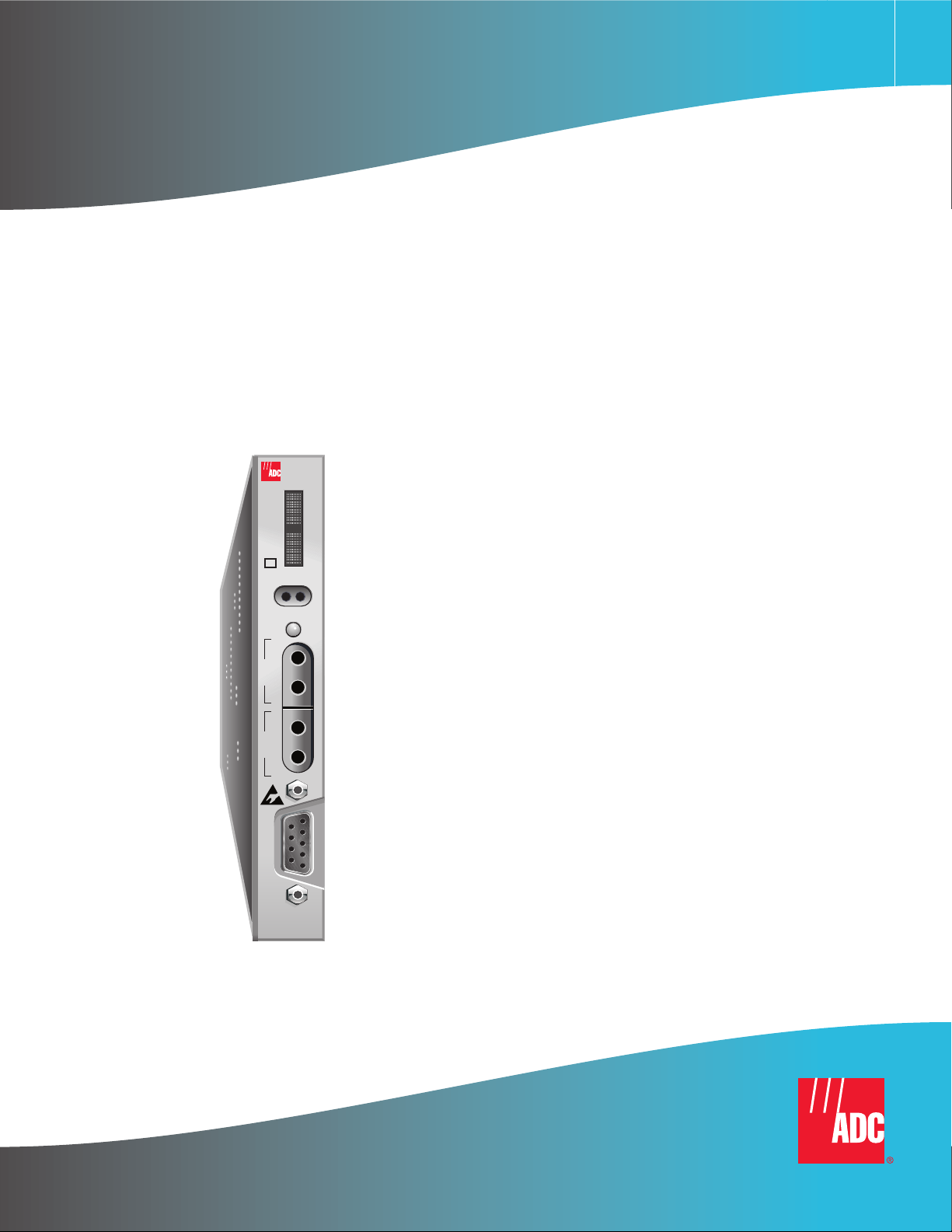
Figure 1 shows the H2TU-C-319 List 4E front panel. Table 1 on page 4 describes the front -panel components. F or
pinout diagrams of the H2TU-C-319 List 4E card-edge connector and craft port, refer to “Appendix A -
Specifications” on page 65.
HiGain
HDSL2
H
List number
Status LED
Card handle
(CLEI code and
ECI bar code label on
outside of handle)
2
T
U
*
C
3
L
1
4E
9
SETUP
M
S
O
E
D
L
E
STATUS
B
R
G
O
U
L
T
I
N
E
B
R
G
I
N
L
I
N
E
Front-panel display
System option pushbuttons
DSX-1 access jacks
Craft port
R
S
2
3
2
DCE
Figure 1. H2TU-C-319 List 4E Front Panel
H2TU-C-319 List 4E January 9, 2002 3
Page 12

Front Panel LTPH-UM-1049-02, Issue 2
Table 1. Front-Panel Description
Front-Panel Feature Function
Front-panel display Displays four-character status, provisioning, and alarm system messages. The front-panel display
illuminates when power is initially applied. To conserve power the display only remains on for
5 minutes. Using the MODE or LBK pushbuttons reactivates the display and restarts the 5-minute
timer. Refer to Table 2 on page 5 for a listing of the four-character messages.
MODE and LBK system
option pushbuttons
Permits user options to be monitored and modified without the need of a maintenance terminal. Used
to initiate all HiGain loopbacks and test states as well as to display DSX-1 line parameters and line
unit identity.
Status LED The status LED can report the following conditions:
Off Line power is off.
Green Normal operation.
Flashing green HDSL2 acquisition.
Red Fuse alarm.
Flashing red System alarm.
Yellow An H2TU-C Customer Remote Loopback (CREM) or a Network Local Loopback (NLOC) is in effect.
Flashing yellow H2TU-C is in an Armed state.
DSX-1 access jacks
BRG Provides non-intrusive bridging jack access to (IN) and from (OUT) the HDSL2 span at the
MUX DSX-1 interface. Allows the two DS1 payloads to be monitored.
LINE Provides splitting jack access to (IN) and from (OUT) the HDSL2 span at the MUX DSX-1 interface.
Breaks the IN and OUT paths to permit test signal insertion and retrieval.
Craft port (RS-232) Provides bidirectional communication between the unit and an external terminal to allow
configuration and performance monitoring through the maintenance terminal screens.
CLEI and ECI bar code label Provides the human-readable Common Language Equipment Identifier (CLEI) code number and the
Equipment Catalog Item (ECI) bar code number.
List number Identifies the list number of the H2TU-C.
4 January 9, 2002 H2TU-C-319 List 4E
Page 13

LTPH-UM-1049-02, Issue 2 Front Panel
Table 2 lists the front-panel display messages. The fou r-character display reports the code o f an alarm, loopback ,
or diagnostic message and, in some cases, is followed by a second four-character message that modifies the first
message with a value or current configuration setting.
Table 2. Front-Panel Display Messages
Message Full Name Description
ALARM MESSAGES
ACO Alarm Cut Off A system alarm has occurred, and has been retired to an ACO
condition by pressing the LBK pushbutton on the H2TU-C front
panel.
ALRM Alarm Condition Exists A system alarm condition is in effect.
DBER DS1 Bit Error Rate A system DS1 BER alarm is in effect and remains in effect until cleared.
HBER HDSL2 Block Error Rate A system HDSL2 Block Error Rate alarm is in effect.
LA Loop Attenuation Indicates that the attenuation on the HDSL2 loop has exceeded the
LAIS Local Alarm Indication Signal Indicates an AIS (all ones) pattern is being received or transmitted
LLOS Local Loss of Signal Indicates that no signal is detected at the DSX-1 input to the
LOSW Loss of Sync Word Indicates that the HDSL2 loop has lost synchronization.
MAL Margin Alarm The margin on HDSL2 loop has dropped below the threshold
MTA Metallic Test Access Indicates the H2TU-C is in a metallic test access state.
PWR FEED GND Power Feed Ground The HDSL2 loop is grounded.
PWR FEED OPEN Power Feed Open Indicates a line power open condition.
PWR FEED SHRT Power Feed Short Indicates a short between the Tip and Ring of the HDSL2 pair.
PRMF Performance Report Messaging - Far
End
PRMN Performance Report Messaging - Near
End
RAIS Remote Alarm Indication Signal Indicates an AIS (all ones) pattern is being received or transmitted
RLOS Remote Loss of Signal Indicates that no signal is detected at the DS1 input to the H2TU-R.
RRAI Remote RAI—Remote Alarm
Indication at the H2TU-R (Net signal
has errors.)
SPN1 Span Number Accompanies the LOSW alarm and identifies the span where the
TRCI Transmit RAI-CI—TX RAI-CI
Indication - Customer Installation at
the H2TU-R (Net signal does not have
errors.)
TUC Transmission Unit Central Office Accompanies the HBER, MAL, and LA alarm and indicates that the
TUR Transmission Unit Remote End Accompanies the HBER, MAL, and LA alarm and indicates that the
maximum threshold value.
at the H2TU-C DS1 input or output ports.
H2TU-C. Causes a system alarm.
(0 to 15 dB) as set by the operator.
H2TU-R PRM-FE BER threshold has been exceeded.
H2TU-R PRM-NE BER threshold has been exceeded.
at the H2TU-R DS1 input or output ports.
Causes a system alarm.
Indicates an RAI alarm (yellow LED) from the CPE with errors from
the line unit or network.
LOSW alarm occurred.
Upon reception of an RAI (yellow LED) from the CPE, the H2TU-R
sends RAI-CI toward the network if the network signal received at the
H2TU-R is clear. If the network signal is impaired (LOS, AIS, or Loss
of Frame [LOF]), then the RAI is automatically passed on to the
network.
alarm has occurred at the H2TU-R remote unit.
alarm has occurred at the H2TU-R remote unit.
Continued
H2TU-C-319 List 4E January 9, 2002 5
Page 14

Front Panel LTPH-UM-1049-02, Issue 2
Table 2. Front-Panel Display Messages (Continued)
Message Full Name Description
LOOPBACK MESSAGES
CLOC Customer Local Loopback Signal from customer is looped back to the customer at the
H2TU-R.
CREM Customer Remote Loopback Signal from customer is looped back to the customer at H2TU-C.
NLOC Network Local Loopback DSX-1 signal is looped back to the network at the H2TU-C.
NREM Network Remote Loopback DSX-1 signal is looped back to the network at the H2TU-R.
SMJK Remote SmartJack Loopback DSX-1 signal is looped back to the network at the H2TU-R
DIAGNOSTIC MESSAGES
A = xx Maximum Loop Attenuation The Attenuation (A) message appears followed by xx, where xx is
ACQ Acquisition The multiplexers of the H2TU-C and H2TU-R (or the H2TU-C and
ARM HiGain System Armed Armed to respond to Intelligent Repeater Loop (ILR) codes.
BAD RT? No Response from H2TU-R The H2TU-C receives no response from the H2TU-R and all HDSL2
FERR Framing Bit Error Occurred Framing bit error occurred at H2TU-C DSX-1 input.
FLDL Flash Download Flash download of firmware upgrades. Contact Customer Service
HES HDSL2 CRC Error H2TU-C HDSL2 Loop Cyclical Redundancy Check (CRC) error.
LBPV Local Bipolar Violation A bipolar violation has been received at the DSX-1 input to the
M=xx HDSL2 Loop Margin Indicates the power of the received HDSL2 signal relative to noise
MNGD Managed The H2TU-C is under control of the HMU-319 Network management
PWR FEED OFF Power Feed Off HDSL2 span power has been turned off by setting the PWFD option
PWR FEED ON Power Feed On Indicates that the HDSL2 loop is not grounded or shorted.
SIG Signaling The transceivers of the H2TU-C and H2TU-R (or the H2TU-C and
SmartJack module.
the loop attenuation of the longest (maximum loss) span, measured
in dB.
first regenerator) are trying to establish synchronization over the
HDSL2 loop of Span 1.
loop conditions are normal. Therefore, the integrity of the H2TU-R
or the HDSL2 loop is questionable.
for upgrade procedures (see “Appendix D - Product Support” on
page 75).
H2TU-C.
(S/N with respect to 21.5 dB). Any value of 6 dB or greater is
adequate for reliable system operation.
unit. In this state, the front-panel craft port and pushbuttons are
disabled.
to off, or HDSL2 span power has been turned off by use of the A2LB
Intelligent Office Repeater (IOR) Power Down code.
first regenerator) are trying to establish contact with each other over
the HDSL2 loop of Span 1.
Continued
6 January 9, 2002 H2TU-C-319 List 4E
Page 15

LTPH-UM-1049-02, Issue 2 Front Panel
Table 2. Front-Panel Display Messages (Continued)
Message Full Name Description
SYSTEM INFORMATION MESSAGES
(a)
CODE xxxx Line Code: AMI or B8ZS The DS1 line code setting: Alternate Mark Inversion (AMI) or Bipolar
with 8-Zero Substitution (B8ZS).
FRM xxxx Frame: SF, ESF, or UNFR Defines the type of frame pattern being received from the DSX-1:
SuperFrame (SF), Extended SuperFrame (ESF), or Unframed
(UNFR).
LATT xx Loop Attenuation The current loop attenuation threshold setting measured in decibels.
LIST xx H2TU-C List Number The list number of the H2TU-C.
MARG xx Margin The current margin threshold setting measured in decibels.
VER x.xx H2TU-C Software Version Number The software version number (x.xx).
(a) System information messages are displayed in Scroll Mode. To scroll through the messages, press the MODE pushbutton for
3 or more seconds.
H2TU-C-319 List 4E January 9, 2002 7
Page 16
Installation LTPH-UM-1049-02, Issue 2
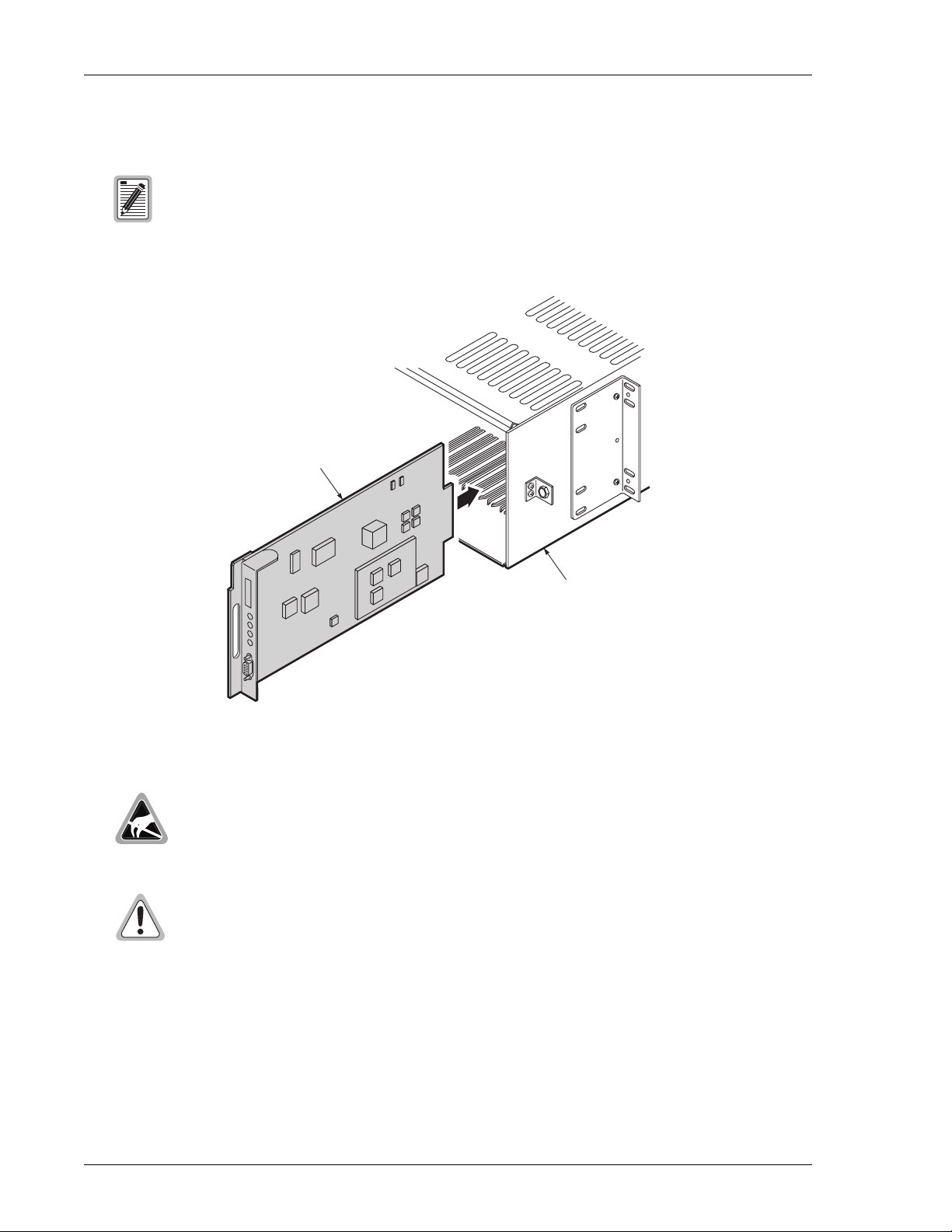
INSTALLATION
Upon receipt of the equipment, ins pect th e con tents for signs of dam age . If the e quipm ent has
been damaged in transit, immediately report the extent of damage to the transportation
company and to ADC.
H2TU-C-319
CO shelf
Figure 2. Installing the H2TU-C-319 List 4E into a Shelf
When installing an H2TU-C in a chassis , be sure to wear an antistatic wrist strap. Avo id touching
components on the circuit board.
To comply with the intrabuilding wiring requirements of GR-1089 CORE, Section 4.5.9, the
shields of the ABAM-type cables that connect the H2TU-C DSX-1 output ports to the
cross-connect panel must be grounded at both ends.
1 Align the H2TU-C with the enclosure slot guides, then push the unit in until it touches the backplane
card-edge connector.
2 Place your thumbs on the H2TU-C front panel and push the H2TU-C firmly into the slot guides until the unit
clicks into the backplane and is properly seated.
8 January 9, 2002 H2TU-C-319 List 4E
Page 17

LTPH-UM-1049-02, Issue 2 Installation
VERIFICATION
Once the H2TU-C is installed, verify that it is operating properly. To do this, monitor the following:
• Status LED
• Status messages reported by the front-panel display (Table 2 on page 5 lists the status messages).
Verification without an H2TU-R Remote Unit
If there is no H2TU-R remote unit installed:
1 Verify that the H2TU-C powers up. The front-panel display illuminates and reports status messages. (See
Table 2 on page 5 lists the messages.)
2 Verify that the H2TU-C attempts to communicate with a remote unit (status LED flashes red). Even if a
remote unit is not present, the following events should occur:
a The front-panel display reports various four-character status messages.
b The H2TU-C again attempts communicatio n with a remote unit until a remote unit is detected.
Verification with an H2TU-R Remote Unit
If an H2TU-R remote unit has been installed:
1 Verify that the H2TU-C powers up. (The front-panel display illuminates and reports various status messages.)
2 Verify that the H2TU-C attempts to communicate with the remote unit (status LED flashes red). One of the
following occurs:
• If the remote unit is successfully identified and the HDSL2 loop synchronizes, the H2TU-C status LED
lights a steady green. The H2TU-C reports normal margin messages o n the front-panel display.
• If the remote unit is not identified, the H2TU-C reports four-character status messages. The H2TU-C
attempts communication again and reports four-character status messages. The H2TU-C repeats this
cycle until a remote unit is detected.
3 Verify that a valid DS1 signal has been applied to the H2TU-C and the H2TU-R.
• If no DS1 signal is being applied to either the H2TU-C or the H2TU-R inputs, then the appropriate DS1
alarms (LLOS or RLOS) display on the front panel and the status LED flashes red.
• If a valid DS1 signal is being supplied to the H2TU-C and H2TU-R, then DS1 alarm indications should
be absent and the status LED should be a steady green.
H2TU-C-319 List 4E January 9, 2002 9
Page 18

Provisioning LTPH -UM-1049-02, Issue 2
PROVISIONING
There are two provisioning methods:
• Use the MODE and LBK pushbuttons on the front panel of the H2TU-C to:
– Set system options
– Reset the H2TU-C to its factory default settings for system options
– Display system option settings (scroll mod e)
– Select system loopbacks
– Select MTA test mode
• Use a maintenance terminal, such as an ASCII terminal or a PC running terminal emulation software,
connected to the H2TU-C craft port or an HMU craft port to access the maintenance screens. Figure 3 on
page 13 shows the maintenance screen. This provides full access to all H2TU-C status, histor y, inventory, and
provisioning screens.
No dip switches or jumpers are required to provision the H2TU-C as it contains a non-volatile
RAM (NVRAM) which stores the system option settings. System option settings are retained if
shelf power is lost or if the H2TU-C is unplugged.
USING THE MODE AND LBK PUSHBUTTONS
Setting Options through MODE and LBK
To provision the H2TU-C through the MODE and LBK pushbuttons on the front panel:
1 Press the MODE pushbutton for 1 second and then release it. The front panel display alternately shows the
first system parameter and its current setting.
2 Press the LBK pushbutton to step through all possible settings of the selected paramete r.
3 After the desir ed s e ttin g ha s been selected, press the MODE pushbutton. This updates the current displayed
parameter to the selected setting, then advances to the next configurable parameter. After the last parameter
has been selected, a CONF NO message appears on the front-panel display.
4 Do one of the following:
• To cancel the session without saving the requested parameter changes, press the MODE pushbutton or
do nothing. After 30 seconds, the display returns to its normal mo de without saving the new changes.
• To accept the requested parameter changes, press the LBK pushbu tton. A CONF YES message displays,
and the display returns to its normal mode after saving the new changes.
10 January 9, 2002 H2TU-C-319 List 4E
Page 19

LTPH-UM-1049-02, Issue 2 Provisioning
Resetting to Factory Default Values
All user options for the H2TU-C, described in Table 5 on page 18 , can be set to the factory default values using
the MODE and LBK pushbuttons. To set the user options to their default values:
1 Press the LBK pushbutton for 6 seconds until the following message appears:
DFLT NO
2 Press the LBK pushbutton until the DFLT NO message is displayed.
The message changes to DFLT YES indicating the factory default values are now in effect and the display
returns to the normal mode.
To terminate the DFLT mode without setting the factory default values, do one of the following:
• Press the MODE pushbutton to return to the normal display mode.
• Wait 30 seconds for the unit to return to the normal display mode.
Displaying System Parameter Settings
To scroll through the current settings of all system parameters, press the MODE pushbutton for 3 or more seconds.
The H2TU-C displays the following parameters:
• H2TU-C software version number
• H2TU-C list number
• Type of frame pattern received from the DSX-1
• Line code of the signal received from the DSX-1
• All user-configured parameter settings
• Loop attenuation threshold setting
• Margin alarm threshold setting
Disabling an Alarm
System alarms can be disabled by pressing the LBK pushbutton on the H2TU-C front panel. This executes an
ACO and returns the H2TU-C to its non-alarm state. For more information, see “Retiring System Alarms” on
page 53.
Loopback Modes
See “Loopback Operation” on page 55 for instructions on using the MODE and LBK pushbuttons to activate
loopbacks.
H2TU-C-319 List 4E January 9, 2002 11
Page 20

Provisioning LTPH -UM-1049-02, Issue 2
USING A MAINTENANCE TERMINAL
Connecting to a Maintenance Terminal
The craft port on the front panel allows you to connect the H2TU-C to a maintenance terminal (ASCII terminal
or PC running a terminal emulation program). Once connected to a maintenance terminal, you can access the
maintenance, provisioning, and performance screens.
To connect to a maintenance terminal:
1 Connect a standard 9-pin terminal cable to the RS-232 craft port, as shown in Figure 1 on page 3, on the
front panel.
2 Connect the other end of the cable to the serial port on the maintenance terminal.
3 Start a terminal emulation program such as Procomm that emulates a VT100 terminal.
4 Con fi gur e the main tenan ce ter mi nal to the following communication settings:
• 9600 baud
• No parity
• 8 data bits
• 1 stop bit
• Hardware flow control to OFF
5 If necessary, press + to refresh the HiGain HDSL2 logon screen.
CTRL R
The Logon Screen
The HiGain HDSL2 maintenance terminal screens allow you to mo nitor, provision, and troubleshoot an H2TU-C
system.
To select a menu from the HiGain HDSL2 logon screen, shown in Figure 3 on page 13, do one of the following:
• Press the underlined letter of the menu.
• Use the arrow keys to select the menu and press .
Table 3 summarizes the navigational keys. They are also listed in the onscreen Help menu. Table 4 on page 13
describes t he Logon screen menus.
(a)
Key
SPACEBAR
ENTER
Return to the parent menu.
ESC
or + Select the submenu or item above the current one, or return to the previous menu.
CTRL E
↑
or + Select the submenu or item below the current one.
CTRL X
↓
→
or + Select the menu or item to the right of the current one.
CTRL D
←
or + Select the menu or item to the left of the current one, or return to the previous menu.
CTRL S
+ Refresh the screen.
CTRL R
(a) Legacy management units require the use of control keys instead of arrow keys.
← →
ENTER
Table 3. Navigational Keys for the HiGain HDSL2 Maintenance Terminal Screens
Function
Cycle through selections.
Activate the current setting or choice, or display a menu.
12 January 9, 2002 H2TU-C-319 List 4E
Page 21

LTPH-UM-1049-02, Issue 2 Provisioning
Most VT100 emulation programs support a print s cree n o ption. For Wind ow s-ba sed prog ra ms ,
such as Procomm or HyperTerminal, see the Help menu for instructions.
Menu bar
Monitor Performance Event Log Config Inventory Report Rlogon Help
+------------------------------------------+
||
| ADC DSL Systems, Inc. |
| HiGain HDSL2 |
||
| Voice: 800.638.0031 |
| Fax : 714.832.9924 |
||
+------------------------------------------+
ID: xxxx--xxxx--xxxx--xxxx 08/01/2001 06:38:12 H2TU-C System: OK
Circuit ID Date and Time Logon Device System Status
Figure 3. Logon Screen
Table 4. Logon Screen Menus
Press this key: To access this menu: Menu Functions
M
P
E
C
I
O
R
H
Monitor Monitors loopbacks and alarms, and provides a graphical representation of
circuit activity, including ES, UAS, SES, and line code.
Performance Provides performance and alarm histories for current, 24-hour, 48-hour, or
31-day periods for either the DS1 or HDSL2 interface.
Event Log Identifies the 100 most recent system events and reports the date and time of
occurrence.
Config Provides standard configuration options, ADC options, date and time setting,
and a reset option (factory settings). Also provides a master clear option that
clears all performance, alarm, and event log entries.
Inventory Provides product information about the various devices that are in the system
and lists circuit and device identifications.
Report Provides four types of reports: Full Report, Short Report, System Information
Report, and Event Report.
Rlogon/Rlogout Remote logon can be performed from the H2TU-C or H2TU-R. The screen
displays “R
logout” when the H2TU-C or H2TU-R is remotely logged on to the
other unit at the end of the circuit.
To logoff the remote unit, press . “Rlogout” changes to “Rlogon”. The unit is
now locally logged on until is pressed again to reinitiate the remote logon.
Help Provides a glossary of terms used in the maintenance screens, a list of
navigational keys, and ADC contact information.
R
R
H2TU-C-319 List 4E January 9, 2002 13
Page 22

Provisioning LTPH -UM-1049-02, Issue 2
PROVISIONING TASKS
After the H2TU-C is successfully installed, perform these basic provisioning tasks:
• Set date and time (see “Setting Date and Time” on this page).
• Set circuit ID numbers (see “Setting Circuit ID Numbers” on page 15).
• Make any configuration changes (see “Configuring the System” on page 16).
• Clear history, alarm, and event log screens to remove miscellaneous data during startup (see “Clearing the
History, Alarm, and Event Log Screens” on page 33).
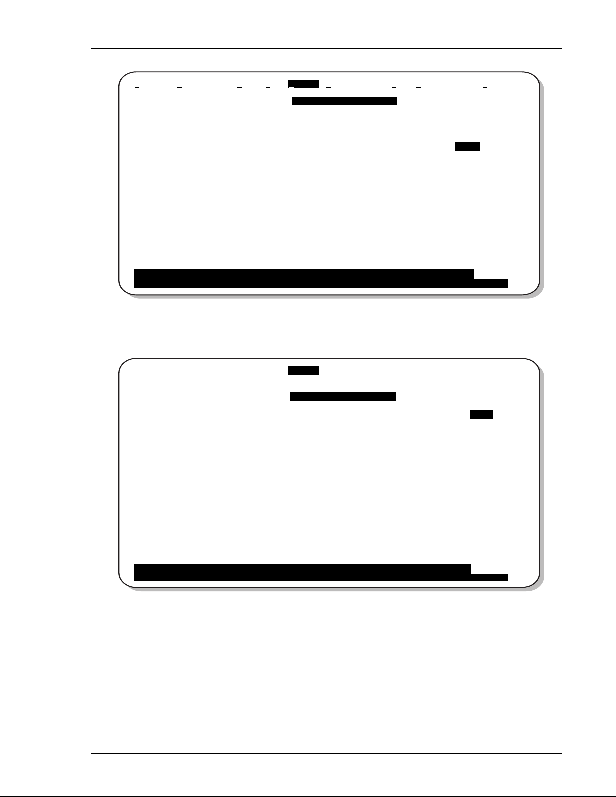
Setting Date and Time
Monitor Performance Event Log Config Inventory Report Rlogon Help
ID: xxxx--xxxx--xxxx--xxxx 08/01/2001 06:38:12 H2TU-C System: OK
+-----------------------+
| Standard Options -> |
| ADC Options -> |
| Test Mode -> |
| Date and Time -> |
+---------------------------------+
| Date (mm/dd/yyyy) : 08/01/2001 |
| Time (hh:mm[:ss]) : 06:40:11 |
+---------------------------------+
Figure 4. Config Menu - Date and Time
1 Press to select the Config menu.
2 Use the and arrow keys to select Date and Time, then press .
C
↑ ↓
ENTER
3 Type the date in the format indicated, then press .
4 Type the time in the format indicated (entering seconds is optional), then press .
14 January 9, 2002 H2TU-C-319 List 4E
ENTER
ENTER
Page 23

LTPH-UM-1049-02, Issue 2 Provisioning
Setting Circuit ID Numbers
The Inventory menu provides product information on all units in the system and allows setting of the circuit and
unit identification numbers.
Monitor Performance Event Log Config Inventory Report Rlogon Help
-------------------------- Product Information ---------------------------Unit : H2TU-C H2TU-R
Product : H2TU-C-319 H2TU-R-402
List : 4E 6E
Sw Ver. : 3.00 3.00
Build # : 10 25
Checksum : 0x604A 0x9616
H2 Xcvr : L1-HB2 1.31 L1-RA2 1.31
Serial # : 01232456789 0123456789
CLEI : VACHYVYGAA XXXXXXXXXX
Mfg. Date: 6-1-2001 6-1-2001
-------------------- Circuit and Unit Identifications ---------------------
Circuit ID : xxxx--xxxx--xxxx--xxxx
H2TU-R ID : xxxx--xxxx--xxxx--xxxx
Circuit Notes:
ID: xxxx--xxxx--xxxx--xxxx 08/01/2001 06:42:07 H2TU-C System: OK
Figure 5. Inventory Screen
1 Press to select the Inventory menu.
2 Type the Circuit ID number, then press .
3 Type the ID numbers of all other devices listed in the system, pressing after each entry.
I
ENTER
ENTER
H2TU-C-319 List 4E January 9, 2002 15
Page 24

Provisioning LTPH -UM-1049-02, Issue 2
Configuring the System
The Config menu (see Figure 6 below) allows you to make the following changes:
• Standard options (see “Making Changes to Standard and ADC Options” on page 16).
• ADC options (see “Making Changes to Standard and ADC Options” on page 16).
• Date and time (see “Setting Date and Time” on page 14).
• Master clear (see “Clearing the History, Alarm, and Event Log Screens” on page 33).
• Reset to factory default configuration (see “Resetting to Factory Defaults” on page 32 ).
Monitor Performance Event Log Config Inventory Report Rlogon Help
ID: xxxx--xxxx--xxxx--xxxx 08/01/2001 06:38:12 H2TU-C System: OK
+-----------------------+
| Standard Options -> |
| ADC Options -> |
| Test Mode -> |
| Date and Time -> |
| Master Clear |
| Set Factory Defaults |
+-----------------------+
Figure 6. Config Menu
Making Changes to Standard and ADC Options
Figure 7 and Figure 8 on page 17 show the Standard and ADC configuration options. Standard o ptions are tho se
supported by HiGain HDSL2 units when conn ected to units fro m other vend ors. ADC options are an extended set
of options that are only available when using HiGain u nits exclusively. For a descri ption of each option and a list
of possible option settings, refer to Table 5 on page 18 and Table 6 on page 19. To make changes to these options:
1 Press to select the Config menu.
2 Use the and arrow keys to select Standard Options or ADC Options, then press .
C
↑ ↓
ENTER
3 Use the arrow keys to select an option.
4 Press the to cycle through the available settings for that option.
5 Press to activate your choice.
16 January 9, 2002 H2TU-C-319 List 4E
SPACEBAR
ENTER
Page 25
LTPH-UM-1049-02, Issue 2 Provisioning
Monitor Performance Event Log Config Inventory Report Rlogon Help
+-----------------------------------------------------+
| Loopback Timeout (LBTO) : 120 min |
| Loop Attenuation Threshold (LATT) [0-40] : 32 dB |
| Margin Threshold (MARG) [0-15]: 5 dB |
| DS1 Frame Formatting (FRMG) : AUTO |
| DS1 Line coding (DS1) : B8ZS |
| H2TU-C Equalization (EQL) : 0 ft |
| H2TU-R Line Buildout (RLBO) : -7.5 dB |
| Alarm Pattern (ALMP) : AIS |
| H2TU-R TLOS Loopback (TLOS) : DIS |
| Power Back Off Network (PBON) : DEF |
| Power Back Off Customer (PBOC) : DEF |
+-----------------------------------------------------+
Use <Spacebar> to cycle through option settings and <Enter> to activate
ID: xxxx--xxxx--xxxx--xxxx 08/01/2001 06:43:31 H2TU-C System: OK
+-----------------------+
| Standard Options -> |
Figure 7. Con fig Menu - Standard Options (defaults sh ow n)
Monitor Performance Event Log Config Inventory Report Rlogon Help
+-----------------------+
| Standard Options -> |
| ADC Options -> |
+-------------------------------------------------+
| Line Power Feed (PWRF) : ON |
| Remote Provisioning (RTPV) : ENA |
| Bipolar Violation Transparency (BPVT) : DIS |
| DS1 BER (DBER) : DIS |
| HDSL2 BER Threshold (HBER) : 1E-6 |
| Special Loopback Mode (SPLB) : GNLB |
| Smartjack Loopback (LPBK) : ENA |
| Minor Alarm (ALM) : DIS |
| Network AIS Pattern (NAIS) : CI |
| Performance Report Messaging (PRM) : S+N |
| SF-RAI to SF-RAI-CI toward NET (RACI) : ENA |
| ESF-RAI to SF-RAI Overwrite (ROVR) : ENA |
| H2TU-R DS1 Frame Conversion (CONV) : ACON |
| Fractional T1 Mode (FT1) : DIS |
| Active DS1 Port (ADS1) : MUX |
+-------------------------------------------------+
Use <Spacebar> to cycle through option settings and <Enter> to activate
ID: xxxx--xxxx--xxxx--xxxx 08/01/2001 06:43:31 H2TU-C System: OK
Figure 8. Config Menu - ADC Options ( defaults shown)
H2TU-C-319 List 4E January 9, 2002 17
Page 26

Provisioning LTPH -UM-1049-02, Issue 2
Table 5 describes the Standard Config scr een options and lists their front-panel dis play codes. Table 6 on page 19
describes the ADC Config screen options and lists their front-panel d isplay codes. Selections in bold typeface are
the factory default settings.
Table 5. H2TU-C-319 List 4E Standard Config Menu Options
Standard Config
Menu Options
Loopback Timeout LBTO NONE Disables automatic time-out cancellation of all loopbacks.
Loop Attenuation
Threshold
Margin Threshold MARG 0 to 15 dB Determines the minimum allowable margin below which a system alarm can
DS1 Frame
Formatting
DS1 Line Coding DS1 B8ZS Places both the H2TU-C and H2TU-R into their B8ZS modes.
H2TU-C Equalization
See “H2TU-C
Equalization (EQL)
Option.” on page 22.
H2TU-R Line
Buildout
Alarm Pattern
See “Alarm Pattern
(ALMP) Option.” on
page 22.
H2TU-R TLOS
Loopback
Power Back Off
Network
Front-Panel
Display
Code
LATT 0 through
FRMG AUTO Configures the line unit to operate in an auto-framing (AUTO) mode.
EQL 0 ft Sets the Equalizer to DSX-1 for 0 to 132 feet.
RLBO 0 dB Sets the DS1 RLBO level toward the Customer Interface (CI).
ALMP AIS Enables the HiGain HDSL2 system to output an AIS payload at its DS1 ports
TLOS ENA Enables a logic loopback at the H2TU-R when an LOS occurs at its DS1 input,
PBON DEF Configures the power output levels of the H2TU-C network unit towards the
Selection Description
20 Sets automatic cancellation of all loopbacks to 20 minutes after initiation.
60 Sets automatic cancellation of all loopbacks to 60 minutes after initiation.
120 Sets automatic cancellation of all loopbacks to 120 minutes after initiation.
40 dB
32 dB Default value. Zero disables the alarm.
5 dB Default value.
UNFR Configures the same as AUTO except unframed payloads do not cause the
AMI Places both the H2TU-C and H2TU-R into their AMI modes.
133 ft Sets the Equalizer to DSX-1 for 133 to 265 feet.
266 ft Sets the Equalizer to DSX-1 for 266 to 398 feet.
399 ft Sets the Equalizer to DSX-1 for 399 to 532 feet.
533 ft Sets the Equalizer to DSX-1 for 533 to 655 feet.
-7.5 dB Sets the DS1 RLBO level toward the CI to -7.5 dB.
-15 dB Sets the DS1 RLBO level toward the CI to -15 dB.
LOS Enables the HiGain HDSL2 system to output an LOS condition at its DS1 ports
DIS Disables TLOS logic loopback.
ENH Configures the power output levels of the H2TU-C network unit towards the
Determines the maximum loop attenuation before an alarm is declared. Zero
disables the alarm. The loop attenuation threshold can only be set through the
maintenance screens.
occur. Zero disables the alarm.
The Margin Alarm Threshold can only be set through the maintenance
screens.
It detects and locks to both SF or ESF DS1 frame patterns. Line and path
performance parameters are maintained and displayed. Unframed payloads
will cause the ES-P and SES-P counters to increment.
ES-P and SES-P counters to increment.
for LOSW and LOS DS1. For priority resolution, see Figure 30 on page 54 for
LOS/AIS response priorities.
for LOSW and LOS DS1.
if enabled at the H2TU-R. For priority resolution, see Figure 30 on page 54.
customer to comply with the Default template as defined in Section 6.1.4.2 of
ANSIT1.E1.4.
customer to comply with the Enhanced template as defined in Section 6.1.4.2
of ANSIT1.E1.4.
Continued
18 January 9, 2002 H2TU-C-319 List 4E
Page 27

LTPH-UM-1049-02, Issue 2 Provisioning
Table 5. H2TU-C-319 List 4E Standard Config Menu Options (Continued)
Standard Config
Menu Options
Power Back Off
Customer
Front-Panel
Display
Selection Description
Code
PBOC DEF Configures the power output levels of the H2TU-R network unit towards the
network to comply with the Default template as defined in Section 6.1.4.2 of
ANSIT1.E1.4.
ENH Configures the power output levels of the H2TU-R network unit towards the
network to comply with the Enhanced template as defined in Section 6.1.4.2
of ANSIT1.E1.4.
Table 6. H2TU-C-319 List 4E ADC Config Menu Options
ADC Config Menu
Options
Line Power Feed PWRF OFF Disables powering to the HDSL2 pair.
Remote Provisioning RTPV ENA Enables remote provisioning.
Bipolar Violation
Transparency
See “Bipolar
Violation
Transparency
(BPVT) Option” on
page 22.
DS1 BER Threshold
See “DS1 BER
(DBER) Option” on
page 22.
HDSL2 BER
Threshold
See “HDSL2 BER
Threshold (HBER)
Option” on page 22
and “System Alarm
Output Pin” on
page 70.
Special Loopback
Mode
SmartJack Loopback LPBK ENA Enables the HiGain HDSL2 system to recognize all in-band SmartJack
Front-Panel
Display
Selection Description
Code
ON Keeps the HDSL2 line voltage at nominal -185 Vdc.
DIS Disables remote provisioning.
BPVT ENA Enables BPVs and HDSL2 CRC errors at the DS1 input to be converted into
DS1 BPVs at the DS1 output at the distant end. This makes HiGain HDSL2
transparent to BPVs.
DIS Disables BPV Transparency.
DBER ENA Enables the fixed 24-hour DS1 BER threshold.
DIS Prevents the generation of a system alarm due to DS1 BER.
HBER 1E-6 System alarm relay contact closes and the Status LED flashes red when the
Block Error Rate (BER) exceeds 10
1E-7 System alarm relay contact closes and the Status LED flashes red when BER
exceeds 10
-7
.
-6
.
NONE Prevents generation of a system alarm due to BER.
SPLB GNLB Configures the HiGain HDSL2 system to respond to the generic in-band
loopback codes.
A2LB Configures the HiGain HDSL2 system to respond to the in-band loopback
codes of the Teltrend addressable repeater.
A3LB Configures the HiGain HDSL2 system to respond to the in-band loopback
codes of the Wescom addressable repeater.
A4LB Configures the HiGain HDSL2 system to respond to the in-band loopback
codes of the Wescom Mod 1 addressable repeater.
loopback commands.
DIS Configures the HiGain HDSL2 system to ignore all in-band SmartJack
loopback commands.
Continued
H2TU-C-319 List 4E January 9, 2002 19
Page 28

Provisioning LTPH -UM-1049-02, Issue 2
Table 6. H2TU-C-319 List 4E ADC Confi g Menu Options (Continued)
ADC Config Menu
Options
Front-Panel
Display
Code
Selection Description
Minor Alarm ALM ENA Enables the generation of the output alarm on pin H when a system alarm
condition occurs.
DIS Disables the generation of the output alarm on pin H when a system alarm
condition occurs.
Network AIS Signal NAIS CI If ALMP is set to AIS, this option specifies which pattern is sent to the network
when a remote LOS or AIS occurs. When configured for CI, an AIS-CI pattern
is sent to the network.
AIS When configured for AIS, an AIS pattern is sent to the network.
Performance Report
Messaging
PRM SPRM The H2TU-R generates Supplemental PRM (SPRM) every second if no PRM
is received from the CPE within 5 seconds of a reset or if an LOS/AIS/LOF
condition occurs. TL1 commands and responses are enabled.
NPRM The H2TU-R generates Network PRM (NPRM) if no PRM is present from the
CPE. If the CPE is sending PRMs, NPRM is generated every second in addition
to the existing PRM. TL1 commands and response are enabled.
S + N The H2TU-R generates an NPRM which is tagged onto an SPRM every
second. The H2TU-R generates SPRM if no PRM is present from the CPE. If
the CPE is sending PRM, the PRM is converted to an SPRM. TL1 commands
and responses are enabled.
OFF ESF Datalink (DL) is completely transparent. No PRMs are generated. There
are no TL1 responses unless the system is first armed by a TL1 command,
which enables performance monitoring.
SF RAI to SF RAI-CI
Toward Network
See “SF RAI to SF
RAI-CI Toward
RACI ENA Allows a DS1 SF-RAI (yellow alarm) signal received by the H2TU-R to be
converted to an SF-RAI-CI signal toward the network.
DIS Prevents conversion of the DS1 SF-RAI to SF RAI-CI. It does not prevent SF
RAI-CI to ESF RAI-CI from occurring when FCON is active.
Network (RACI)
Option” on page 23.
ESF RAI to SF RAI
Overwrite
ROVR ENA If the CONV option is set to FCON or ACON, an ESF DS1 payload from the
network with an embedded RAI pattern is converted to an SF-RAI pattern
toward the CI at the H2TU-R.
See “ESF RAI to SF
DIS Prevents conversion to an SF-RAI pattern.
RAI Overwrite
(ROVR) Option” on
page 23.
H2TU-R DS1 Frame
Conversion
See “H2TU-R DS1
CONV ACON Auto (ACON) detection of framing and potential frame conversion at the
remote.
OFF Framing determined by the DS1 frame formatting option.
Frame Conversion
(CONV) Option” on
page 23.
FCON Auto detection of framing and forced frame format conversion (FCON) at the
H2TU-R.
Fractional T1 Mode
See “Fractional T1
(FT1) Option” on
page 26.
FT1 ENA Enables system response to DDS latching loopback commands for fractional
T1 applications and enables CPE disconnect or trouble indication. See
Figure 30 on page 54 for LOS/AIS response priorities.
DIS Disables system response to DDS latching loopback commands for fractional
T1 applications and CPE disconnect or trouble indications.
Continued
20 January 9, 2002 H2TU-C-319 List 4E
Page 29

LTPH-UM-1049-02, Issue 2 Provisioning
Table 6. H2TU-C-319 List 4E ADC Config Menu Option s (Continued)
ADC Config Menu
Options
Active DS1 Port
See “Dual DSX-1
Port Option” on
page 31.
Front-Panel
Display
Selection Description
Code
ADS1 MUX The MUX mode selects the DSX-1 (MUX) port as the active source for the DS1
Signal to transmit to the HSDL Line Port #1.
An AIS signal is sent to the auxiliary Port #2. Equalizer settings apply to the
MUX DSX-1 port. The AUX equalizer is set to 0.
AUX The AUX mode selects the auxiliary DSX-1 Port #2 as the active source for
DS1 signal to transmit to the HDSL Line Port.
In this case, the MUX port is used as a monitor or splitting device for electrical
test access. Equalizer settings apply to the AUX DSX-1 port. The MUX
equalizer is set to 0.
CTHR Activates the Cut-through mode. This mode electrically connects the MUX
port to the AUX port and the H2TU-C operates as a cut-through card.
This is used when one tributary from the Wideband 3190 MUX card is required
to appear at the DSX-1 interface to the local central office. Equalizer settings
apply to the MUX DSX-1 port. The AUX Equalizer is set to 0.
H2TU-C-319 List 4E January 9, 2002 21
Page 30

Provisioning LTPH -UM-1049-02, Issue 2
HDSL2 BER Threshold (HBER) Option. The HBER option permits the monitoring of loop integrity and
reporting of alarms when excessive errors are detected. The PM primitive used for this purpose is the CRC
checksum performed on the HDSL2 f rame for bo th directions of transmission. It is, therefore, called a block er ror
rate rather than the bit error rate associated with the DS1 interface. The CRC errors and counts are displayed on
the Monitor screen for both the H2TU-C and H2TU-R. The HBER option allows an alarm to be generated if the
total number of CRCs at either the H2TU-C or H2TU-R exceeds the selected BER threshold during the last
1-minute interval .
• HBER option = 1E-6. Alarm is generated if CRC > 93
• HBER option = 1E-7. Alarm is generated if CRC > 9
Once initiated, the HBER count clears when the CRC count drops below the selected threshold. Selecting NONE
inhibits this alarm.
H2TU-C Equalization (EQL) Option. Equalization is the configuration of sys tem transmission characteristics
within specified limits. An adaptive equalizer inserts a frequency-shaped loss that corresponds to an equivalent
addition of an appropriate cable length. By simulating the additional cable loss necessary for correct operation,
the equalizer compensates for a range of variation in transmission path characteristics.
Alarm Pattern (ALMP) Option. To improve HiGain HDSL2 compatibility with the switch-to-protect features
used in Digital Loop Carrier (DLC) feeder applications, the H2TU-C has an Alarm Pattern (ALMP) option that
allows you to select either an AIS or LOS DS1 output payload for the following alarms:
• LOSW on any loop
• LOS DS1
Bipolar Violation Transparency (BPVT) Option. The H2TU-C improves compatibility with Digital Loop
Carrier (DLC) feeder applications because of its ability to transmit DS1 BPV occurrences between its DS1
interfaces. This feature is required to support protection sw itching in DLC applications. Each DLC terminal must
be able to monitor the integrity of its Receive DS1 payload and then switch to the protect line when the integrity
of the path drops below specific user s elected limits . An essential req uiremen t of this feature is the need for each
DLC terminal to detect BPVs in its DS1 input. Standard HDSL systems correct DS1 BPVs at the input and
therefore prevent them from being detected by the DLC terminals to which they are connected. The H2TU-C and
its associated remote units remove this limitation and become BPV transparen t by det ecting and counting input
BPVs at each end and then by replicating them at the DS1 output port of the distant end.
The BPV count is converted into BPVs at the distant end during the following second at a rate of 1 BPV every
-3
128 DS1 bits up to a maximum of 12000 (BER = 7.7 x 10
-3
exceeds the maximum 10
BER required by mo st DLC systems.
). This maximum rate is more than adequate since it
DS1 BER (DBER) Option. The DS1 BER alarm occurs when any of the DS1 or DSX-1 performance
monitoring parameters listed in Table 7 exceed the counts shown for the 24-hour period between 12:00:00 AM
-6
through 11:59:59 PM . These thr eshol ds corr espond to a 10
BER. All PM counters clear to zero at 12:00:00 AM
or when Master Clear is selected. See “Clearing the History, Alarm, and Event Log Screens” on page 33.
Table 7. DS1 and DSX-1 24-hour PM Threshold
Parameter Threshold Count
CV-L (BPV) 133,400
ES-L, ES-P, PRM, PDVS-L 648
SES-L, SES-P 100
UAS-P, UAS-L 10
22 January 9, 2002 H2TU-C-319 List 4E
Page 31

LTPH-UM-1049-02, Issue 2 Provisioning
SF RAI to SF RAI-CI Toward Network (RACI) Option. In general, the Remote Alarm Indication Customer Installation (RAI-CI) signal is a RAI signal which contains a signature indicating that an LOF or AIS
failure has occurred within the customer’s network.
RAI-CI is transmitted toward the network when these two conditions are si multan e ously true at the point from
which RAI-CI is originated (at the H2TU-R, toward the network):
• RAI is received from the CI
• No LOF, LOS, or AIS failure is detected in the signal received from the network.
Since RAI-CI meets the definition of RAI, it may be detected and used exactly as an RAI.
For ESF, the RAI-CI signal is a repetitive pattern with a period of 1.08 seconds. RAI-CI is formed by sequentially
interleaving 0.99 seconds of the unscheduled message 00000000 111 111 11 (ri g ht-t o-l ef t) , whi ch repr esents RAI
in the DL, with 90 milliseconds of the message 00111110 11111111 (right-to-left) to flag the signal as RAI-CI.
For SF, the SF-RAI-CI signal is transmitted in-band by setting each of the 24 channel time slots to 1000 1011
(left-to-right). In addition to the criteria specified above, the generation of SF-RAI-CI has to be held for 1 second
to examine the DS0 channels for the presence of a frame with an all-zeroes pattern. If present, the generation of
SF-RAI-CI is suspended for the duration of the all-zeroes pattern.
In all SF environments, the H2TU-R automatically converts a CPE DS1 payload with an embedded RAI signal
into an RAI-CI pattern toward the network if the RACI option is enabled (default). Such a conversion affects the
payload as described above. Disable RACI to avoid this payload-affecting conversion.
The SF RAI to SF RAI-CI option is only applicable in an all SF framing environme nt. If SF to ESF
conversion is active (the CONV o ption is se t to eith er ACON o r FCON), th e SF RAI is conv erted
into ESF RAI in the FDL, regardless of the RACI setting.
ESF RAI to SF RAI Overwrite (ROVR) Option. If the ESF RAI to SF RAI Overwrite (ROVR) option is
enabled, it allows a network ESF RAI or ESF RAI-CI pattern to be converted into a CPE SF RAI or SF RAI-CI
pattern, and overwrites the payload bits with the specific alarm patterns.
If the ROVR option is disabled, it prevents conversion of a network ESF payload with an embedded RAI pattern
and preserves the integrity of the CPE payload as it was originally tran sm itted.
Power Back Off (PBOC and PBON) Option. Power Back Of Network (PBON) and Power Back Off
Customer (PBOC) allow the HDSL circuit to support two tr ansmit power templates: default (DEF/higher level)
and enhanced (ENH/lower level). These are defined in Section 6.1.4. 2 of the ANSI T1E1.4 HDSL2 standard. Each
HDSL2 receiver detects the level it is receiving during the s tart-up, pre-activation s equence. It then compares this
level to the level it should be receiving according to the PBON and PBOC option settings (DEF or ENH). If the
received level is outside the template limits, the receiver sends a message to the upstream HDSL2 transmitter
requesting the proper level. These levels are adjusted only during the start-up routine or if the PBON or PBOC
option settings are changed during no rmal operation. Since the ENH template levels are up to 15 dBm below those
of the DEF template, the ENH setting can be used to red uce cros stalk lev els into adjacen t circuits. (For examp l e,
if crosstalk noise is being induced by the H2TU-R, set the PBO C option to its lower (ENH) level settin g.
Conversely, if the HDSL2 signal at the H2TU-R is being affected by crosstalk noise induced from adjacent pairs,
set the PBOC option to its higher (DEF) level setting.
Changing these Power Back Off option settings on a live circuit causes the HDSL2 loop to
momentarily drop and then reacquire sy nchronization. This setting can also af fect the operating
margins.
H2TU-R DS1 Frame Conversion (CONV) Option. Frame format conversion is only applicable to the
remote H2TU-R, but selectable by the H2TU-C or H2TU-R. This option enables the network to be ESF, which is
H2TU-C-319 List 4E January 9, 2002 23
Page 32

Provisioning LTPH -UM-1049-02, Issue 2
used to embed SPRM or NPRM into the datalink toward the network. During conversion, frame bit errors are
regenerated to ensure transparency.
The HDSL2 system attempts to find ESF or SF framing or determines that no framing exists. The DS1 framing is
then synchronized with the HDSL2 frame. If the framing is lost, the system generates an Out-of-Frame (OOF)
defect which results in UAS-P. As a result, the system reverts to frame search mode.
This option has the following settings:
• OFF: No frame conversion takes place. All framing issues are determined by the FRMG option settings of
AUTO and UNFR.
• ACON: This is the automatic conversion setting. If the system detects ESF from the network and SF fro m the
CPE, it automatically converts the CPE SF to ESF toward the network as well as the n e twork ESF to SF
toward the CPE.
Upon power-on-reset, after loopdown, or after changing the frame conversion option, the framing needs to
be re-established before a complete conversion takes place. If there is a failure condition (LOS, AIS, or LOF)
during steady state, the previous co nversion st ate is maintained to en sure continuity when the system retu rns
from the failure condition.
If SF is received from the network, the H2TU-R forces an ESF toward the network for about 1.5 seconds.
This signals to the far-end PM-NIU at the network boundary that frame convers ion is requested. If the far-end
PM-NIU is capable of conversion, it changes the framing to ESF. If not, then the H2TU-R reverts to SF and
does not apply any conversion.
If an ESF is received from the CPE, it is passed on to the network, and the network’s inbound framing is
passed on to the CPE.
• FCON: This is the forced conversion setting. Table 8 below lists the HiGain HDSL2 responses to both the
ACON and FCON settings for the CONV option. The responses are identical, except in cases 3 and 4. In these
cases, the FCON reply is attempting to force the network ( or the far-end PM-NIU) to send ESF. It also alerts
the CPE with an AIS alarm pattern while forcing the ESF to the network. Continuity is maintained as for
ACON. Table 9 on page 25 and Table 10 on pa ge 25 list the ESF and SF frame formats, respectively.
Table 8. Response to H2TU-R DS1 Frame Conversion Options
ACON Option FCON Option
Case Number NET Transmit CPE Transmit
1 ESF SF ESF → SF
2 ESF ESF ESF → ESF
3 SF ESF SF → SF
4 SF SF SF → SF
NET > CPE
NET < CPE
ESF ← SF
ESF ← ESF
ESF ← ESF
SF ← SF
NET > CPE
NET < CPE
ESF → SF
ESF ← SF
ESF → ESF
ESF ← ESF
SF → AIS
ESF ← ESF
SF → AIS
ESF ← SF
24 January 9, 2002 H2TU-C-319 List 4E
Page 33

LTPH-UM-1049-02, Issue 2 Provisioning
Table 9. Extended SuperFrame Format
Frame Bits
ESF Number
Framing Pattern
Sequence (FPS) - 2 kps
Frame Bit for Datalink
(FDL) - 4 kbps
Check (CRC) Bits - 2 kbps
1 m
2 C1
3 m
4 0
5 m
6 C2
7 m
8 0
9 m
10 C3
11 m
12 1
13 m
14 C4
15 m
16 0
17 m
18 C5
19 m
20 1
21 m
22 C6
23 m
24 1
Cyclical Redundancy
Table 10. SuperFrame Format
SF Number
Terminal Framing Bit SuperFrame Signaling Bit
1 1
2 0
3 0
4 0
5 1
6 1
7 0
8 1
9 1
10 1
11 0
12 0
H2TU-C-319 List 4E January 9, 2002 25
Frame Bits
Page 34

Provisioning LTPH -UM-1049-02, Issue 2
Fractional T1 (FT1) Option. Fractional T1 circuits can be used in feeder networks to provide frame relay
service. If such circuits are maintained b y a DDS test group, then these circuits must respond to DDS/DS0 latching
loopback commands, the only tool test groups have at their disposal. A latching loopback, once it has been
initiated by the correct sequence, remains locked or “latched” until the correct loopdown sequence has been
detected.
The FT1 option, when enabled, allows the H2TU-C to respond to DS0 latchin g loopback commands and therefore,
supports fractional T1 frame-relay applications. This is in addition to the standard full bandwidth T1 2-in-5 loopup
and 3-in-5 loopdown SmartJack commands. FT1 supports both the full T1 enable commands and the new DDS
latching loopback commands, which must also be enabled. (For more information about latching loopback
commands, refer to BellCore TA-TSY-000077, Issue 3, April 1986.)
The FT1 option supports both the DDS NI and DDS DS0 Data Port (DP) latching loopback sequences listed in
Table 11.
Table 11. DD S NI and DS0 DP Latching Loopback Sequence
Enable Sequence
1 35 Transition in Progress (TIP) S0111010
2A 35 NI Loop Select Code (LSC) S1000001
2B 35 DS0 DP Loop Select Code (LSC) S0000101
3 100 Loopback Enable Code (LBE) S1010110
4 35 All Ones S1111111
5 100 LBE S1010110
6 32 Far End Voice (FEV) S1011010
Disable/Loopdown 35 TIP S0111010
Minimum
Number of Bytes
Byte Name Network Code
The sequences in Table 11 are sent in time slot 1. The S in the Network Code column is a “don’t care” bit. The
loopback is activated after the detection of Sequen ce 6. Upon completion of the en able sequence, th e Test Center
continues to transmit FEV bytes in multiples of 20 until FEV confirmation bytes are returned or until about 2
seconds have elapsed. If the confirmation bytes are not received, a failed attempt is reported. Anticipate the
minimum number of bytes when the loopback code is transmitted by a preprogrammed machine test p atter n
generator. This minimum number of bytes will most likely be exceeded when the codes are sent manually. Also,
manual testing may inject random data signals between valid control sequences. The detection algorithm ignores
these occurrences and only responds to valid control codes.
Table 12 lists the relationship between the latching loopback sequences and the specific HiGain HDSL2 loopback
they initiate.
Table 12. HiGain HDSL2 Loopback vs. Latching Sequence
HiGain HDSL2 Loopback Latching Sequence
NREM 1, 2A, 3, 6
NLOC 1, 2B, 3, 6
The NLOC loopback is called tandem DS0 DP loopback. It is used to select one of many loopback points when
there are several identical data ports in tandem. The NI loopback is assigned to the H2TU-R (NREM) since it is
usually located at the Network Interface (NI). The DS0 DP tandem loopback is assigned to th e rest of the HiGain
HDSL2 loopbacks because most DDS test sets support this tandem command set.
The Test Center transmits a group of 40 TIP bytes to loop down the loopback. It continues to transmit TIP bytes
in multiples of 20 until the TIP bytes are not returned or until about 2 seconds have elapsed. If the bytes are absent,
26 January 9, 2002 H2TU-C-319 List 4E
Page 35

LTPH-UM-1049-02, Issue 2 Provisioning
a successful loopdown is reported; otherwise, a failed loopdown is reported. The loop-down can also be initiated
by depressing the H2TU-R loopback control button or by any of the standard 3-in-5 loop-down commands. The
-3
implemented detection/release loopback algorithm functions properly in the presence of a 10
bit error rate.
Since the FT1 mode is a combination of both the full T1 and the latching loopback modes, all codes are always
active. Therefore, if a loopback is initiated by a latching sequence, it can be looped down by either a latching or
generic loopback and vice versa. All loopback commands are completely symmetric in the FT1 mode.
If the latching sequence shown in Table 12 on page 26 is interrupted for more than 20 minutes, the detection is
cleared, and the H2TU-C reverts back to its initial state where it searches for the initial sequence 1.
After a successful latching sequence terminates in a latched loopback state, this state remains until the Disable
command is detected, or until the LBTO option of NONE, 20, 60, or 120 minutes has expired, whichever occurs
first.
The unframed AIS pattern that is normally sent toward the network for a CI LOS fault condition must be replaced
by the new patterns listed in Table 13 when the FT1 loopback option is selected.
Table 13. Response of H2TU-C-319 List 4E and H2TU-R to LOS and AIS
H2TU-C Output Pattern
Case
FT1
Option
H2TU-C
Input
Framing Payload FDL
H2TU-R
Input
H2TU-R
Output
1 ENA SF SF 01111110 N/A LOS/AIS 01111110
UNFR
2 ENA ESF ESF 01111110 X
(a)
LOS/AIS 01111110
UNFR
3 ENA LOS/AIS SF 01111110 N/A LOS/AIS 01111110
UNFR
4 ENA LOS/AIS SF PL X
5 ENA LOS/AIS ESF PL X
(a) “Don’t care” bit
(a)
(a)
SF/PL AIS RCV LLOS/LAIS ALRM
ESF/PL AIS RCV LLOS/LAIS ALRM
Status Screen
RCV
RLOS/RAIS
XMT IDLE
RCV
RLOS/RAIS
XMT IDLE
RCV
RLOS/RAIS
XMT IDLE
Front-Panel
Display
ALRM
RLOS/RAIS
ALRM
RLOS/RAIS
ALRM
RLOS/RAIS
LLOS/LAIS
LLOS/LAIS
H2TU-C-319 List 4E January 9, 2002 27
Page 36

Provisioning LTPH -UM-1049-02, Issue 2
Test Access
The H2TU-C’s PC board’s card-edge connector, shown in Figure 33 on page 68, has three separate segments
labeled S1 (segment 1), S2 (segment 2), and S3 (segment 3). S3 contains the standard 3192 pin connection s. The
two extra segments, S1 and S2, have pin connections that support additional features called Dual DSX-1 port
option and Metallic Test Access (MTA), respectively, as shown in Figure 9 below through Figure 12 on page 30.
Test
center
DACS
or
MUX
DSX-1
Cable
test
Golden
H2TU-C
319
Golden
H2TU-R
Unit
Test Facilities
set
or
HDSL2
Wire
Line
Simulator
or
Test
Pair
HMS-358
Backplane
TB6
R
OUT
T
MUX DSX-1
TB6
R
IN
T
S2
13
31
S3
1
A
2
B
S2
14
32
Figure 9. Metallic T est Access Blo ck Diagram
H2TU-C-319 (UUT)
MTAF
R
T
Framer
R
T
MTAE
HDSL2
Xceiver
K2
K1
HDSL2
Span
S3
Cable
pair
H
2
T
U
R
9
K
28 January 9, 2002 H2TU-C-319 List 4E
Page 37

LTPH-UM-1049-02, Issue 2 Provisioning
Metallic Test Access. Figure 9 on page 28 shows the block diagram of the metallic test access features which
are under control of the two relay s, K1 and K2. The S2 metallic test access ports (IN or OUT) are bus ed to terminal
block TB6 located on the HMS-358 backplane, as shown in Figure 10 below. Figure 11 displays the location of
TB6 on the HMS-358 backplane.
Test
center
Backplane
CRT AUD
CRTVIS
MAJ AUD
MAJ VIS
MIN AUD
MIN VIS
SYS ID
DACS
MUX
Jumpers
NC
TB2
HMS-358
Backplane
AUX DSX-1
TB6
OUT
13
31
R
T
MUX DSX-1
TB6
R
T
14
IN
32
Figure 10. MTA Relays
DSX-1
TEST ACCESS
NO
COM
TX
RX
R
T
TB3
BITS TIMING
RING
TIP
A-
A+
B+ B-
TB4
HMS-358 Shelf
Defective H2TU-L
S1
S2
MTAF
Standby H2TU-L
S3
MTAE
K2-S
SSC1
EXT ACO
SSC2
SHIELD
SSC3
SSC4
SHIELD
SSC5
SSC6
TB5
K1-D
21
S3
9
K
S3
SHIELD
H
D
S
L
2
No connection
METALLIC
TEST ACCESS
TR
TB6
FAN
COM NO
TB7
H
2
S
T
P
U
A
N
R
OUT
IN
Figure 11. Metallic Test Access TB6 on HMS-358 Backplane
Both relays are energized or pulled down when the user either activates the MTA option from the front p anel (o r
the test menu) or upon command from the HMU. K1 opens the HDSL2 cable pair between the H2TU-Cs
transceiver and the incoming span and connects the latter to the Metallic Test Access Facilities (MTAF) OUT
T and R pins on TB6. K2 connects the HDSL2 transceiver to the Metallic Test Access Equipment (MTAE) IN
T and R pins on TB6. Typical MTAF and MTAE test interfaces are shown in Figure 9 on pa ge 28. A cable test
set connected to the out port of TB6 can be used to perform cable tes ts on the 2 wire HDSL2 cable pairs out to the
remote H2TU-R. Alternately, the OUT port of TB6 can connect to a golden H2TU-C which, in conjunction with
a T1 test set, can be used to perform system tests on the original circuit minus its H2TU-C an d thu s iso late an y
trouble to the equipment or the facilities.
H2TU-C-319 List 4E January 9, 2002 29
Page 38

Provisioning LTPH -UM-1049-02, Issue 2
The MTAF IN port of TB6 can connect to an external test facility circuit consisting of an HDSL2 wire line
simulator or test pair and a golden H2TU-R remote HDSL2 unit. This connection allows the H2TU-C Unit Under
Test (UUT) to be tested from its DSX-1 interface on the simulated test circuit. This allows any problem to be
isolated to either the equipment or the facilities. Since this MTA test event disrupts service, it is always
accompanied by an MTA/LOSW alarm that is displayed on both the front panel and status screen.
Simultaneous access of the MTAF and MTAE backplane buses by more than one H2TU-C would connect two
loops and two transceivers together and must be prevented. Such a conflict is inhibited when the shelf is under
command of the HMU-319 management unit. However, when the H2TU-Cs are under manual control, the conflict
can occur if the MTA command is issued to two line units in the same shelf o r in different shelve s if the TB3 and
TB6 ports are bussed together to create a single test access to an entire bay. Theref ore, the u ser mus t be aware o f
this potential conflict and take care to avoid it.
Figure 10 on page 29 shows a future enhancement of the H2TU-C that uses separate commands to co ntrol the two
test relays K1 and K2. This allows the IN and OUT ports of TB6 to be connected to each other which creates a
circuit that allows a suspected H2TU-C to be replaced by a standby H2TU-C. The MTAF relay K1-D is activated
in the defective H2TU-C unit and the MTAE relay K2-S activated in the standby H2TU-C unit. This allows the
original facility circuit of the defective H2TU-C to be connected, by way of the TB6 jumpers to the standby
H2TU-C unit. The test center can then switch the DSX-1 interface from the defective H2TU-C unit to the standby
unit within a DACS or M13 MUX circuit to complete the test circuit.
To external
DSX-1
cross-connect
panel
HMU
M
U
X
O
p
t
I
o
n
In
Port 2
Auxiliary
DSX-1
Out
In
DSX-1
Out
S1
A
u
x
L
I
U
M
U
X
L
I
U
ADS1
Option
control
M
A
C
M
A
C
M
A
C
M
C
R
1
E
q
s
T
u
19
2
20
S3
7
1
A
(MUX)
2
B
M = MUX or SPTF
A = Auxiliary
C = CTHR (Cut through) or SPTE
a
l
R1
I
z
T1
e
r
User option
Micro
T
R
E
e
q
s
u
T
t
a
l
J
R1
I
a
z
c
e
T1
k
r
s
e
l
e
c
t
S
e
l
e
c
t
A
H2TU-C-319, L4E
LOS
DET
AIS/QRSS
I/O
T1
Payload
MONF
MONE
MONF = Monitor Facilities
MONE = Monitor Equipment
SPTF = Split Facilities
SPTE = Split Equipment
H
D
S
L
S3
2
F
r
a
m
e
r
R
T
r
a
T
n
s
c
e
I
v
e
r
H
9
D
S
K
L
2
H
2
S
T
P
U
A
N
R
Figure 12. H2TU-C-319 List 4E Block Diagram
30 January 9, 2002 H2TU-C-319 List 4E
Page 39

LTPH-UM-1049-02, Issue 2 Provisioning
The separate control of K1 and K2 permits another test scenario. Two external HDSL2 spans can be looped
together at TB6 if the two H2TU-C line units that connect to the two spans both enable their MTAF states and
close K1 in each unit. This will loop the two pairs together and allow metallic cable tests to be performed from
any point in the loop where both pairs can be accessed.
Future enhancements to the H2TU-C will also allow the following seven bit in-band command s to control K1 and
K2:
MTAF (Enable K2) 1010011
MTAE (Enable K1) 1011110
DISABLE K1 or K2 1011011
Dual DSX-1 Port Option
Figure 12 on page 30 is the block diagram of the H2TU-C Dual DSX-1 Port option. The Input/Output (I/O) DS1
payload from the HDSL2 span is routed to either of the two Line Interface Un its (LIU) Auxiliary (AUX) LIU and
Multiplexer (MUX) LIU as controlled by the following three settings of the Active DSX-1 (ADS1) user options:
• MUX (M)
In the MUX setting, the I/O DS1 payload from the field is connected to the MUX LIU which connects it to
the MUX IN and OUT DSX-1 signal levels at the S3 card-edge connector interface. This interface connects
to one of the HiGain M13 multiplexers that plugs into the HMS-358 shelf. An AIS out-of-service indicating
pattern is sent toward the Auxiliary LIU for the MUX setting. Additionally, the input port of the AUX LIU
is monitored for a valid DS1 signal and an AUX LOS alarm is displayed, if no signal is present.
• AUX (A)
The AUX setting of the ADS1 option routes the I/O DS1 payload to the AUX LIU. This LIU converts the
payload to the IN and OUT signal levels at the AUX DSX-1 output pins at S1 of the card-edge connector
which provides access to an external DSX-1 cross-connect panel.
The AUX setting of ADS1 also supports a subset of four more user options if the MUX DSX-1 interface is
connected to a HiGain MUX. These four options, which can only be initiated from the shelf’s HMU-319
management card, are called Monitor Facilities (MONF), Monitor Equipment (MONE), Split Facilities
(SPTF), and Split Equipment (SPTE) and are described as follows:
• The MONF setting routes the signal received from the facilities at the I/O DS1 payload interface to the
MUX, through the MUX LIU, where it can be examined by the MUX test circuits.
• The MONE setting operates like the MONF setting but operates on the signal received from the
equipment.
• The SPTF setting forces ADS1 to its MUX setting and presents the full I/O DS1 facilities payload to the
MUX for testing.
• The SPTE forces ADS1 to its CTHR setting and presents the full DSX-1 equipment signal from the AUX
port to the MUX for testing. Since both the SPTF and SPTE settings disrupt the original AUX circuit,
both modes create minor alarm conditions identified as either ALPM SPTF or ALRM SPTE
• Cut-through (CTHR) (C)
The CTHR setting of ADS1 disconnects both LIUs from the I/O DS1 payload an d co nnects the two LIUs in
tandem. This allows a DSX-1 circuit from the normal DSX-1 interface (typically a HiGain MUX) to be
cross-connected to the external DSX-1 cross-connect panel by way of the AUX DSX-1 interface.
The Equalizer Select option settings apply to eith er the AUX or MUX port as de termin ed by the
setting (AUX or MUX) of the ADS1 option. The equalizer of the unselected port is set to 0. The
equalizer settings apply to the AUX port when the Cut-Through setting is selected.
H2TU-C-319 List 4E January 9, 2002 31
Page 40

Provisioning LTPH -UM-1049-02, Issue 2
Resetting to Factory Defaults
Resetting the H2TU-C to its original factory settings may cause interruption of service.
To reset the H2TU-C to its original factory defaults:
1 Press to select the Config menu.
2 Use the and arrow keys to select Set Factory Defaults, then press .
3 Press if you want to reset the H2TU-C, or press to cancel this action.
C
↑ ↓
Y N
Monitor Performance Event Log Config Inventory Report Rlogon Help
+-----------------------+
| Standard Options -> |
| ADC Options -> |
| Test Mode -> |
| Date and Time -> |
| Master Clear |
| Set Factory Defaults |
+-----------------------+
SETTING FACTORY DEFAULTS . . . SERVICE *MAY* BE INTERRUPTED! ARE YOU SURE (Y/N)?
ID: xxxx--xxxx--xxxx--xxxx 08/01/2001 06:38:12 H2TU-C System: OK
ENTER
Figure 13. Config Menu - Reset to Factory Defaults
32 January 9, 2002 H2TU-C-319 List 4E
Page 41

LTPH-UM-1049-02, Issue 2 Provisioning
Clearing the History, Alarm, and Event Log Screens
Select Master Clear to clear the History, Alarm and Event Log screens after the system has been installed and is
functioning properly. This removes miscellaneous data acquired during the startup ses sio n and ensures that you
have meaningful data thereafter.
Monitor Performance Event Log Config Inventory Report Rlogon Help
Clear ALL performance, alarm and event log entries. Are you sure (Y/N)?
ID: xxxx--xxxx--xxxx--xxxx 08/01/2001 06:38:12 H2TU-C System: OK
+-----------------------+
| Standard Options -> |
| ADC Options -> |
| Test Mode -> |
| Date and Time -> |
| Master Clear |
| Set Factory Defaults |
+-----------------------+
Figure 14. Co nfig Menu - Master Clear
To clear the Event Log, press to select the Event Log screen, then press to clear the screen.
E L
To clear an individual history or alarm screen, do the following:
1 Press to select the Performance screen.
2 Press the to select an interface (H2TU-C DS1, H2TU- R DS1, H2TU-C HDSL2, or
3 Press the to select the type of statistics (Current, Alarm History, 25 Hour History,
P
SPACEBAR
H2TU-R HDSL2), then press .
SPACEBAR
48 Hour History, or 31 Day History), press after your selection.
ENTER
ENTER
– Selecting 31 Day History allows you to clear the Current, 25 Hour, 48 Hour, and 31 Day
performance history screens for the selected interface.
– Selecting Alarm Histo ry allows you to clear the alarm history sc reen for the selected interface. For
information about the DS1 and HDSL2 alarm screens, see Table 17 on page 45.
4 Press to clear the screen.
L
To clear all history, alarm, and event log screens:
1 Press to select the Config screen.
2 Use the and arrow keys to select Master Clear.
3 Press to clear all screens.
C
↑ ↓
Y
H2TU-C-319 List 4E January 9, 2002 33
Page 42

Monitoring System Activity and Pe rfo rm anc e LTPH -UM-1049-02, Issue 2
MONITORING SYSTEM ACTIVITY AND
PERFORMANCE
The H2TU-C-319 List 4E provides the following maintenance screens for monitoring system activity and
assessing performance:
• The Monitor screens provide a graphical representation of circuit activity and allow initiation of lo opb acks .
• The Performance screens provide current, 24-hour, 48-hour, and 31-day performance histories and a
continuous alarm history.
• The Event Log provides a description of the 100 most recent events which include their origin, time and date
of occurrence, and message.
34 January 9, 2002 H2TU-C-319 List 4E
Page 43

LTPH-UM-1049-02, Issue 2 Monitoring System Activity and P erform ance
USING THE MONITOR SCREEN TO VIEW SYSTEM ACTIVITY
1 Press to view the system diagram.
M
Figure 15 shows an armed circuit with an active loopback and alarms . Terms used on the s ystem diagram are
defined in the onscreen Help menu glossary. Abnormal situations are highlighted on the diagram. Table 14
on page 36 describes the screen field.
DS1 Errors
Monitor Performance Event Log Config Inventory Rlogon Report Help
ESF +---+ +---+
B8ZS |H2C| |H2R|
------->|-+ |||-AIS ->
ARM | | |M =19 M =18 | |
ES =3 | | |||ES=1
SES=3 | | |=MAL ==========================================| | SES=1
UAS=0 | | | | | UAS=0
ESF | | |UAS=38 UAS=0 | |
B8ZS | | |||
<-------<-+ |||
----------------------------------LOOPBACKS-----------------------------------Active Loopback: NLOC-HG
Press <Space> to select LB New Loopback: LPDN - Loopback H2TU-C towards Network
and <Enter> to activate (LPDN,NLOC,CREM,NREM,CLOC)
ID: xxxx--xxxx--xxxx--xxxx 08/01/2001 06:47:30 H2TU-C System: Alarm
Armed mode Margin Loop attenuation Alarm type HDSL2 Errors
| | |||
| | |LA=25 LA =25 | |
| | |ES =41 ES =1 | | PRM=0
| | |SES=41 SES=1 | |
|LPF| | |<-RLOS +---+ +---+
Line code and framing
Active loopback System status
Figure 15. Monitor Screen - Active Loopback with Alarms
2 To initiate a loopback, press the to cycle though the loopback choices. Press to select your
SPACEBAR ENTER
choice.
When prompted with the message: Are you sure (Y/N)?,press to init iate the loopback or to
Y N
cancel. For more information about loopbacks and troubleshooting, see “Testing” on page 52.
3 To initiate a loopdo wn of all active loopbacks, press the to select LPDN, then press .
When prompted with the message: Are you sure (Y/N)?,press to init iate the loopdown or to
SPACEBAR ENTER
Y N
cancel.
H2TU-C-319 List 4E January 9, 2002 35
Page 44

Monitoring System Activity and Pe rfo rm anc e LTPH -UM-1049-02, Issue 2
Table 14. M onitor Scree n Des c ri pt i ons
Field Description
Active Loopback An active loopback is indicated on the lower third of the Monitor screen. Available loopbacks are
indicated by gray text. See Table 22 on page 56 for a summary of the HiGain HDSL2 generic
loopback codes and activation methods.
Alarm Type Indicates type of alarm.
Armed Mode Indicates system is in an armed state and ready for an intelligent repeater (IR) loopback command.
Code Type Type of DS1 line coding used (B8ZS or AMI).
DS1 ES Count Errored Seconds—The sum of the Errored Seconds-Line (ES-L) and Errored Seconds-Path (ES-P)
counts detected on the DS1 input over a 24-hour period. Errors included are: DS1 frame errors,
BPV, and ESF CRC errors.
DS1 SES Count Severely Errored Seconds—The sum of the DS1 Severely Errored Seconds-Line (SES-L) and
Severely Errored Seconds-Path (SES-P) counts over the last 24 hours.
DS1 UAS Count Unavailable Errored Seconds—The number of seconds during which the DS1 input signal was
absent over a 24-hour period.
Frame Type Type of DS1 framing used on the input stream (SF, ESF, or UNFR).
HDSL2 ES Count Errored Seconds—The number of 1-second intervals that contained at least one CRC or LOSW
error. This value is a running total of the last 24 Hours.
HDSL2 SES Count Severely Errored Seconds—The number of 1-second intervals that contain at least 50 CRC errors
or one or more LOSW defects. (An LOSW defect occurs when at least three consecutive HDSL
frames contain one or more frame bit errors.) This value is a running total of the last 24 hours.
HDSL2 UAS Count Unavailable Errored Seconds—The number of seconds the HDSL2 loop is unavailable. This occurs
after 10 contiguous HDSL SES and is retired after 10 contiguous non-SES seconds. This value is
a running total of the last 24 hours.
ID Circuit identification (ID) number.
LA Loop Attenuation—Indicates the attenuation of the Overlapped Pulse Amplitude Modulation
Transmission with Interlocking Spectra (OPTIS) pulse from the distant end. The value is related to
the 196 kHz loss of the cable pair. The loop attenuation is a more direct indication of the loop
attenuation to the OPTIS signal than is the 196 kHz loss. The normal HiGain HDSL2 LA operation
range is from 0 to 40 dB.
LPF Line Power Feed—Indicates the HDSL2 line power is on.
M Margin—The signal-to-noise ratio at all HDSL2 ports, relative to a 10-7 Bit Error Rate.
MAL Margin Alarm—Indicates the margin on HDSL2 loop has dropped below the threshold (0 to 15dB)
as set by the operator.
HG (or PL) HG displays when the loopback was initiated from a HiGain (HG) front panel or by a HiGain
maintenance terminal loopback command. PL displays when the loopback was initiated by a
command embedded in the DS1 data path payload (PL).
PRM The sum of the Performance Report Messaging-Near End (PRM-NE) and Performance Report
Messaging-Far End (PRM-FE) counts.
System Status The presence or absence of an alarm condition is indicated on the lower right corner of all screens.
System: OK indicates that there are no alarms present; System: Alarm indicates the presence of
an alarm. Refer to “Using the Performance Screens to View Alarm Data” on page 44.
36 January 9, 2002 H2TU-C-319 List 4E
Page 45

LTPH-UM-1049-02, Issue 2 Monitoring System Activity and P erform ance
USING THE PERFORMANCE SCREENS TO VIEW PERFORMANCE DATA
The Performance screens display:
• CRC statistics for the HDSL2 or DS1 interface in 31-day, 48-hour, 25-hour, and current history reports.
• Alarm statistics for the DS1 interfaces (Figure 25 on page 44 and Figure 26 on page 45) or DS1 interfaces
(Figure 26 on page 45) on a continuous basis.
To access the performance history screens:
1 Press to select the Performance screen.
2 Press the to select an interface (H2TU-C DS1, H2TU-R DS1, H2TU-C HDSL2, or H2TU-R
3 Press the to select the type of statistics (Current, Alarm History, 25 Hour History, 48 Hour
P
SPACEBAR
HDSL2), then press .
SPACEBAR
History, or 31 Day History), then press .
ENTER
ENTER
H2TU-C-319 List 4E January 9, 2002 37
Page 46

Monitoring System Activity and Pe rfo rm anc e LTPH -UM-1049-02, Issue 2
Performance History at the DS1 Interface
The Performance History for the DS1 interface provides 31-day, 48-hour, 25-hour, and current statistics screens
for the H2TU-C and the H2TU-R (as viewed from the H2TU-C).
Figure 16 below and Figure 17 on page 38 are examples of DS1 performance history screens at the remote unit.
Figure 18 on page 39 is an example of DS1 performance history screens at the line unit. Refer to Table 15 on
page 39 for descriptions of the kinds of errors reported o n DS1 interface scr eens . Asterisk s indicate perfo rman ce
monitoring from the previous day.
Monitor Performance Event Log Config Inventory Report Rlogon Help
-----------------------------------------------------------------------------Date CV-L ES-L SES-L UAS-L PDVS-L ES-P SES-P UAS-P PRM-NE PRM-FE
08/09 ---- -----08/10 ---- -----08/11 ---- -----08/12 ---- -----08/13 ---- -----08/14 ---- -----08/15 ---- -----08/16 ---- -----08/17 ---- -----08/18 ---- -----08/19 ---- -----08/20 1410101210100000
08/21 0002 000000
Press: (N)ext Page, (P)revious Page, C(l)ear History
-----------------------------------------------------------------------------
Use <Space> to cycle through Interface : H2TU-R DS1
choices and <Enter> to view Statistics : 31 Day History
ID: xxxx--xxxx--xxxx--xxxx 08/01/2001 07:05:33 H2TU-C System: OK
H2TU-R DS1 31 Day History (Page 1 of 3)
Figure 16. H2TU-R DS1 31-Day Performance History
Monitor Performance Event Log Config Inventory Report Rlogon Help
-----------------------------------------------------------------------------Time CV-L ES-L SES-L UAS-L PDVS-L ES-P SES-P UAS-P PRM-NE PRM-FE
H2TU-R DS1 25 Hour History (Page 1 of 9)
*22:15 ---- -----*22:30 ---- -----*22:45 ---- -----*23:00 ---- ------
23:15 ---- -----23:30 ---- -----23:45 ---- -----00:00 ---- -----00:15 ---- -----00:30 ---- -----00:45 ---- -----01:00 ---- ------
-----------------------------------------------------------------------------
Use <Space> to cycle through Interface : H2TU-R DS1
choices and <Enter> to view Statistics : 25 Hour History
ID: xxxx--xxxx--xxxx--xxxx 08/01/2001 07:05:33 H2TU-C System: OK
Press: (N)ext Page, (P)revious Page, C(l)ear History
Figure 17. H2TU-R DS1 25-Hour Performance History
38 January 9, 2002 H2TU-C-319 List 4E
Page 47

LTPH-UM-1049-02, Issue 2 Monitoring System Activity and P erform ance
Monitor Performance Event Log Config Inventory Report Rlogon Help
-----------------------------------------------------------------------------Time CV-L ES-L SES-L UAS-L PDVS-L ES-P SES-P UAS-P
*00:00 ---- ---*01:00 ---- ---*02:00 ---- ---*03:00 ---- ---*04:00 ---- ---*05:00 ---- ---*06:00 ---- ---*07:00 ---- ---*08:00 ---- ---*09:00 ---- ---*10:00 ---- ---*11:00 ---- ----
Press: (N)ext Page, (P)revious Page, C(l)ear History
-----------------------------------------------------------------------------
Use <Space> to cycle through Interface : H2TU-R DS1
choices and <Enter> to view Statistics : 48 Hour History
ID: xxxx--xxxx--xxxx--xxxx 08/01/2001 07:05:33 H2TU-C System: OK
H2TU-R DS1 48 Hour History (Page 1 of 4)
Figure 18. H2TU-C DS1 48-Hour Performance History
Table 15. Error Acronyms Used on the DS1 Performance History Screens
Error Acronym Description Error Acronym Description
CV-L Code Violation - Line
Total BPV count.
ES-L Errored Seconds - Line
Seconds with BPV ≥ 1.
SES-L Severely Errored Seconds - Line
Seconds with BPV plus EXZ ≥ 1544 or
LOS ≥ 1.
UAS-L Unavailable Seconds - Line
Seconds with LOS ≥ 1.
PDVS-L Pulse Density Violation Seconds - Line
Seconds with excessive zeroes
(AMI = 16 zeroes, B8ZS = 8 zeroes).
ES-P Errored Seconds - Path
Seconds with SEF
(d)
(SF) ≥ 1.
FE
(a) O nly displays on H2TU-R Per formance Hist ory screens.
(b) Displays on the DS1 Current Statistics screens.
(c) Severely Errored Frame—Two or more frame bit errors occ urring in a 0.75 ms interval for SF or a 3 ms interval for ESF.
(d) FE is a frame bit error.
(c)
, CRC( ESF), or
SES-P Severely Errored Seconds - Path
Seconds with SEF or CRC (ESF) ≥ 320 or
(d)
(SF) ≥ 8 (FT + FS).
FE
UAS-P Unavailable Seconds - Path
A second of unavailability based on SES-P
or AIS ≥ 1.
PRM-NE
(a)
Performance Report Monitoring - Near End
The PRM from CPE indicates errors, and
the signal received from the network at the
remote is error-free.
(a)
PRM-FE
Performance Report Monitoring - Far End
The PRM from the network indicates
errors, and the signal received from the
CPE is error-free.
(b)
B8ZSS
B8ZS Monitored Seconds
Seconds with B8ZS detection when AMI
option is active.
(b)
MSEC
Monitored Seconds of the current
(15 minute/1 hour/1 day) screen.
H2TU-C-319 List 4E January 9, 2002 39
Page 48

Monitoring System Activity and Pe rfo rm anc e LTPH -UM-1049-02, Issue 2
Performance History at the HDSL2 Interface
The HDSL2 interface has 31-day, 48-hour, 25-hour, and curren t statistic screens for the H2TU-C. Figure 19 and
Figure 20 below are examples of 31-day and 48-hour performance history screens. Figure 21 on page 41 is an
example of a 25-hour performance history screen. Refer to Table 16 on page 41 for descriptions of the kinds of
errors reported on all HDSL2 performance screen s. Asterisks indicate performance m onitoring from the prev ious
day.
Monitor Performance Event Log Config Inventory Report Rlogon Help
----------------------------------------------------------------------------Date CV ES SES UAS LOSWS
10/09 - - - - 10/10 - - - - 10/11 - - - - 10/12 - - - - 10/13 - - - - 10/14 - - - - 10/15 - - - - 10/16 - - - - 10/17 - - - - 10/18 - - - - 10/19 - - - - 10/20 - - - - 10/21 14 10 10 14 10
Press: (N)ext Page, (P)revious Page, C(l)ear History
-----------------------------------------------------------------------------
Use <Space> to cycle through Interface : H2TU-C HDSL2
choices and <Enter> to view Statistics : 31 Day History
ID: xxxx--xxxx--xxxx--xxxx 08/01/2001 07:05:33 H2TU-C System: OK
H2TU-C HDSL2 31 Day History (Page 1 of 3)
Figure 19. H2TU-C HDSL2 31-Day Performance History
Monitor Performance Event Log Config Inventory Report Rlogon Help
-----------------------------------------------------------------------------Time CV ES SES UAS LOSWS
*00:00 - - - - *01:00 - - - - *02:00 - - - - *03:00 - - - - *04:00 - - - - *05:00 - - - - *06:00 - - - - *07:00 - - - - *08:00 - - - - *09:00 - - - - *10:00 - - - - *11:00 - - - - -
Press: (N)ext Page, (P)revious Page, C(l)ear History
-----------------------------------------------------------------------------
Use <Space> to cycle through Interface : H2TU-C HDSL2
choices and <Enter> to view Statistics : 48 Hour History
ID: xxxx--xxxx--xxxx--xxxx 08/01/2001 07:05:33 H2TU-C System: OK
H2TU-C HDSL2 48 Hour History (Page 1 of 4)
Figure 20. H2TU-C HDSL2 4 8-Hour Performa nce Hi sto ry
40 January 9, 2002 H2TU-C-319 List 4E
Page 49

LTPH-UM-1049-02, Issue 2 Monitoring System Activity and P erform ance
Monitor Performance Event Log Config Inventory Report Rlogon Help
-----------------------------------------------------------------------------Time CV ES SES UAS LOSWS
*22:15 - - - - *22:30 - - - - *22:45 - - - - *23:00 - - - - -
23:15 - - - - 23:30 - - - - 23:45 - - - - 00:00 - - - - 00:15 - - - - 00:30 - - - - 00:45 - - - - 01:00 - - - - -
Press: (N)ext Page, (P)revious Page, C(l)ear History
-----------------------------------------------------------------------------
Use <Space> to cycle through Interface : H2TU-C HDSL2
choices and <Enter> to view Statistics : 25 Hour History
ID: xxxx--xxxx--xxxx--xxxx 08/01/2001 07:05:33 H2TU-C System: OK
H2TU-C HDSL2 25 Hour History (Page 1 of 9)
Figure 21. H2TU-C HDSL2 2 5-Hour Performa nce Hi sto ry
Table 16. Error Acronyms Used on the HDSL2 Performance History Screens
Error Acronym Description
ES Errored Seconds
Seconds with HDSL2 CRC ≥ 1 or LOSW ≥ 1
SES Severely Errored Seconds
Seconds with HDSL2 CRC ≥ 50 or LOSW ≥ 1
UAS Unavailable Seconds
Based on 10 contiguous SES occurrences
CV Code Violation
Total count of HDSL2 CRC errors.
LOSWS Loss of Sync Word Second
Seconds with LOSW ≥ 1
H2TU-C-319 List 4E January 9, 2002 41
Page 50

Monitoring System Activity and Pe rfo rm anc e LTPH -UM-1049-02, Issue 2
Current Statistics Screens for the DS1 Interface
Examples of current statistics screens are shown below. Figure 22 and Figure 23 show statistics for the DS1
interface at the remote unit and line unit, respectively. These screens report 1-day, 1-ho ur, and 15-minute statistics.
Refer to Table 15 on page 39 for descriptions of the kinds of errors reported on these screens.
Monitor Performance Event Log Config Inventory Report Rlogon Help
----------------------------------------------------------------------------1 Day 1 Hour 15 Min
Start 00:00 12:00 12:30
CV-L 0 0 0
ES-L 0 0 0
SES-L000
UAS-L000
PDVS-L 0 0 0
ES-P 0 0 0
SES-P000
UAS-P000
PRM-NE No PRM Detected
PRM-FE No PRM Detected
B8ZSS000
MSEC 3482 1801 1
------------------------------------------------------------------------------
Use <Space> to cycle through Interface : H2TU-R DS-1
choices and <Enter> to view Statistics : Current
ID: xxxx--xxxx--xxxx--xxxx 08/01/2001 07:05:33 H2TU-C System: OK
H2TU-R DS-1 Current Statistics
Press: C(l)ear Current Statistics
Figure 22. H2TU-R DS1 Current Statistics
Monitor Performance Event Log Config Inventory Report Rlogon Help
----------------------------------------------------------------------------1 Day 1 Hour 15 Min
Start 00:00 12:00 12:30
CV-L 0 0 0
ES-L 0 0 0
SES-L000
UAS-L000
PDVS-L 0 0 0
ES-P 0 0 0
SES-P000
UAS-P000
B8ZSS000
MSEC 3482 1801 1
------------------------------------------------------------------------------
Use <Space> to cycle through Interface : H2TU-C DS-1
choices and <Enter> to view Statistics : Current
ID: xxxx--xxxx--xxxx--xxxx 08/01/2001 07:05:33 H2TU-C System: OK
H2TU-C DS-1 Current Statistics
Press: C(l)ear Current Statistics
Figure 23. H2TU-C DS1 Current Statistics
42 January 9, 2002 H2TU-C-319 List 4E
Page 51

LTPH-UM-1049-02, Issue 2 Monitoring System Activity and P erform ance
Current Statistics for HDSL2 Interface
Figure 24 shows statistics for the HDSL2 interface at the H2TU-C. This screen reports 1-day, 1-hour, and
15-minute statistics. Refer to Tab le 16 on page 41 for descriptions of the kinds of errors reported on this screen.
Monitor Performance Event Log Config Inventory Report Rlogon Help
----------------------------------------------------------------------------1 Day 1 Hour 15 Min
Start 00:00 12:00 12:30
CV 000
ES 000
SES 0 0 0
UAS 0 0 0
LOSWS 3482 1801 1
Margin(dB) LA (dB)
Hi 16
Cur 15 25
Low 12
------------------------------------------------------------------------------
Use <Space> to cycle through Interface : H2TU-C HDSL2
choices and <Enter> to view Statistics : Current
ID: xxxx--xxxx--xxxx--xxxx 08/01/2001 07:05:33 H2TU-C System: OK
H2TU-C HDSL2 Current Statistics
Press: C(l)ear Current Statistics
Figure 24. H2TU-C HDSL2 Current Statistics
H2TU-C-319 List 4E January 9, 2002 43
Page 52

Monitoring System Activity and Pe rfo rm anc e LTPH -UM-1049-02, Issue 2
USING THE PERFORMANCE SCREENS TO VIEW ALARM DATA
To access the alarm history screens:
1 Press to select the Performance menu.
2 Press the to select an interface (H2TU-C DS1, H2TU-R DS1, H2TU-C HDSL2, or
3 Press the until Alarm History is selected, then press .
P
SPACEBAR
H2TU-R HDSL2), then press .
SPACEBAR ENTER
• Press or to page through the alarm history screens.
• Press to clear the selected alarm history screen.
N P
L
ENTER
Alarm History at the DS1 Interface
The Alarm History screen reports DS1 statistics for the H2TU-C, shown in Figure 25 below, and the H2TU-R,
shown in Figure 26 on page 45, on a continuous basis. Th e typ es of alarms r epor ted ar e des crib ed in Tab le 17 on
page 45. Current alarms are shown in reverse video.
Monitor Performance Event Log Config Inventory Report Rlogon Help
-----------------------------------------------------------------------------
Alarm First Last Status Count
SPTE OK 0
SPTF OK 0
LLOS OK 0
LAIS OK 0
DBER DISABLED 0
H2TU-C DS-1 Alarm History
------------------------------------------------------------------------------
Use <Space> to cycle through Interface : H2TU-C DS-1
choices and <Enter> to view Statistics : Alarm History
ID: xxxx--xxxx--xxxx--xxxx 08/01/2001 07:05:33 H2TU-C System: Alarm
Press: C(l)ear Alarm History
Figure 25. H2TU-C DS1 Alarm History Screen
44 January 9, 2002 H2TU-C-319 List 4E
Page 53

LTPH-UM-1049-02, Issue 2 Monitoring System Activity and P erform ance
Monitor Performance Event Log Config Inventory Report Rlogon Help
-----------------------------------------------------------------------------
Alarm First Last Status Count
RLOS OK 0
RAIS OK 0
RAI OK 0
TX RAI-CI OK 0
PRM-NE OK 0
PRM-FE OK 0
DBER 08/16/01 00:37 08/16/01 00:45 OK 7
------------------------------------------------------------------------------
Use <Space> to cycle through Interface : H2TU-R DS-1
choices and <Enter> to view Statistics : Alarm History
ID: xxxx--xxxx--xxxx--xxxx 08/01/2001 07:05:33 H2TU-C System: Alarm
H2TU-R DS-1 Alarm History
Press: C(l)ear Alarm History
Figure 26. H2TU-R DS1 Alarm History Screen
Table 17. DS1 Alarm Descriptions
Screen Alarm Front-Panel Alarm Description
H2TU-C DSI Alarms (see Figure 25 on page 44)
SPTE Split Equipment A test mode initiated by the HMU which splits the AUX port’s DSX-1 payload and sends it to the
MUX port.
SPTF Split Facilities A test mode initiated by the HMU which splits the AUX facility DS payload from the AUX port
#1 and sends it to the MUX port.
(a)
LLOS
LLOS Local Loss of Signal—Loss of the H2TU-C DSX-1 input signal.
LAIS LAIS Line Alarm Indication Signal—Indicates an AIS (all ones) pattern is being detected at the
H2TU-C DS1 input port. The ALMP option determines whether AIS (default) or LOS is sent
towards the CPE.
DBER xxx-DBER Bit Error Rate—The DS1 BER has exceeded the built-in 24-hour threshold limits of
approximately 10
-6
. (xxx denotes either TUC or TUR.)
H2TU-R DS1 Alarms (see Figure 26 above)
(a)
RLOS
RAIS RAIS Remote Alarm Indication Signal—AIS is being detected at the H2TU-R DS1 input port. By
RLOS Remote Loss of Signal— Loss of the H2TU-R DS1 input signal.
default (see Figure 30 on page 54) AIS-CI
(b)
is sent toward the network.
RAI RRAI Remote Alarm Indication—Indicates an RAI alarm (yellow) from the CPE with errors from the
line unit or network.
TX RAI-CI TRCI Transmit RAI-CI - Remote Alarm Indication at the H2TU-R—Upon reception of an RAI (yellow
LED) from the CPE, the H2TU-R sends an RAI-CI towards the network if the network signal
received at the H2TU-R is clear. If the network signal is impaired (LOS, AIS or LOF), then the
RAI is passed on to the network unaltered. This is applicable to SF or ESF framing. In an all SF
environment, RACI must be enabled to convert SF-RAI to SF-RAI-CI.
PRM-NE PRMN Performance Report Monitoring - Near End—The count of the PRM-NE register at the H2TU-R
exceeds the 10
PRM-FE PRMF Performance Report Monitoring - Far End—The count of the PRM-FE register at the H2TU-R
exceeds the 10
-6
BER threshold at 648 events since 12:00:00 AM.
-6
BER threshold at 648 events since 12:00:00 AM.
Continued
H2TU-C-319 List 4E January 9, 2002 45
Page 54

Monitoring System Activity and Pe rfo rm anc e LTPH -UM-1049-02, Issue 2
Table 17. DS1 Alarm Descriptions (Continued)
Screen Alarm Front-Panel Alarm Description
DBER xxx-DBER Bit Error Rate—The DS1 BER has exceeded the built-in 24-hour threshold limits of
approximately 10
(a) T his is a DS1-specific alarm that also issues a minor alarm (sent to the management unit or the backplane), if enabled.
(b) AIS-CI is a modified AIS alarm pattern. Equipment not suited to detect AIS-CI still detects this signal as an AIS. AIS-CI is sent
toward the network indicating that an LOS (RLOS) or AIS (RAIS) has been received from the CPE.
-6
. (xxx denotes either TUC or TUR.)
Alarm History at the HDSL2 Interface
Figure 27 shows the H2TU-C HDSL2 alarm history and Table 18 describes the alarms.
Monitor Performance Event Log Config Inventory Report Rlogon Help
----------------------------------------------------------------------------Alarm First Last Status Count
MTAE OK 0
MTAF OK 0
LOSW OK 0
MAL OK 0
LA OK 0
HBER 08/16/01 00:37 08/16/01 00:45 OK 7
SHORT OK 0
GND OK 0
OPEN OK 0
------------------------------------------------------------------------------
Use <Space> to cycle through Interface : H2TU-C HDLS2
choices and <Enter> to view Statistics : Alarm History
ID: xxxx--xxxx--xxxx--xxxx 08/01/2001 07:05:33 H2TU-C System: Alarm
H2TU-C HDSL2 Alarm History
Press: C(l)ear Alarm History
Figure 27. H2TU-C HDSL2 Alarm History Screen
46 January 9, 2002 H2TU-C-319 List 4E
Page 55

LTPH-UM-1049-02, Issue 2 Monitoring System Activity and P erform ance
Table 18. HDSL2 Alarm Descriptions
Screen Alarm Front-Panel Alarm Description
MTAE MTAE Metallic Test Access Equipment—The H2TU-C is in its MTA/LOSW test state.
MTAF MTAF Metallic Test Access Facility—The H2TU-C is in its MTA/LOSW test state.
LOSW LOSW Loss of Sync Word—The HDSL2 loop has lost synchronization.
MAL xxx-MAL Margin—The margin on the HDSL2 loop has dropped below the minimum threshold value
LA xxx-LA Loop Attenuation—The attenuation on the HDSL2 loop has exceeded the maximum value
HBER xxx-HBER Block Error Rate—The HDSL2 BER has exceeded the set threshold limits of 10
(a)
SHORT
(a)
GND
(a)
OPEN
(a) Displays only on the H2TU-C HDSL2 interface.
PWR FEED SHRT Indicates a short between the Tip and Ring of the HDSL2 pair.
PWR FEED GND The HDSL2 loop is grounded.
PWR FEED OPEN Indicates a line power open condition.
set for the system. (xxx denotes either TUC or TUR.)
set for the HDSL2 loop attenuation threshold. (xxx denotes either TUC or TUR.)
(xxx denotes either TUC or TUR.)
-6
or 10
- 7
.
H2TU-C-319 List 4E January 9, 2002 47
Page 56

Monitoring System Activity and Pe rfo rm anc e LTPH -UM-1049-02, Issue 2
USING THE SYSTEM EVENT LOG TO TRACK EVENTS
To view a running log of system events, press to select the Event Log. The Event Log displays the date and
E
time of the 100 most recent events (most recent displayed first) and provides a description of each event. Table 19
on page 49 lists the event log messages.
• Press or to page through the event log.
• Press to return to the top of the log.
• Press to clear the event log.
N P
T
L
Monitor Performance Event Log Config Inventory Report Rlogon Help
System Event Log (Page 1 of 7)
-----------------------------------------------------------------------------
# Origin Date and Time Entry
1 System 07/21/01 12:25:00 DS1 Alarm Register reset
2 System 07/22/01 12:25:00 HDSL2 Alarm Register Reset
3 System 07/23/01 12:25:00 DS1 Performance Register Reset
4 System 07/24/01 12:25:00 HDSL2 Performance Register Reset
5 System 07/25/01 00:13:32 Time set 12:25:00
6 System 07/26/01 00:13:27 Date set 10/21/00
7 H2TU-C 07/27/01 00:13:27 NLOC: Loop-down
8 H2TU-C 07/28/01 00:11:16 NLOC: Loop-up
9 H2TU-R 07/29/01 00:10:43 DS1 LOS Alarm: End
10 H2TU-R 07/30/01 00:10:30 DS1 LOS Alarm: Begin
11 System 07/31/01 00:04:11 DS1C: AUTO to AMI
12 H2TU-C 08/01/01 00:00:40 HDSL2 LOSW Alarm: End
13 H2TU-C 08/02/01 00:00:02 HDSL2 LOSW Alarm: Begin
14 - EMPTY 15 - EMPTY -
ID: xxxx--xxxx--xxxx--xxxx 08/01/2001 07:07:54 H2TU-C System: OK
Press: (N)ext Page, (P)revious Page, (T)op of Log, C(l)ear Log
Figure 28. System Event Log
48 January 9, 2002 H2TU-C-319 List 4E
Page 57

LTPH-UM-1049-02, Issue 2 Monitoring System Activity and P erform ance
Table 19. Event Log Entry Messages List
Event Log Messages
Any DS1 Alarm History reset
Any DS1 PM register reset
Any HDSL2 Alarm History reset
Any HDSL2 PM register reset
Any Loop Down (any segment)
Any Loop Up (any segment)
Any provisioning option change: <provisioning mnemonic>: changed from <old> to <new>
CPE DBER alarm (1-day threshold crossed of any PM data except PRM-NE or PRM-FE)
CPE DS1 AIS begins/ends
CPE DS1 LOS begins/ends
CPE PRM-NE BER alarm (at the remote only: 1-day threshold crossed of PRM-NE: trouble on CPE receive)
Current statistics reset
Event Log reset
H2TU-C Power up/down
H2TU-R Power up/down
HDSL2 DC pair open begins/ends on any segment
HDSL2 Ground fault begins/ends on any segment
HDSL2 HBER alarm (threshold crossed) on any segment.
HDSL2 loop attenuation (threshold crossed) on any HDSL2 interface
HDSL2 margin alarm (threshold crossed) on any HDSL2 interface
HDSL2 unavailability begins/ends on any segment
Master zero reset
NTWK DBER alarm (1-day threshold crossed of any PM data)
NTWK DS1 LOS begins/ends
NTWK PRM-FE BER alarm (at the remote only: 1-day threshold crossed of PRM-FE: trouble on NTWK far end)
NTWK DS1 AIS begins/ends
Power Feed Open begins/ends
Power Feed Short begins/ends
RAI begins/ends
TX RAI-CI begins/ends (RAI-CI sent from the remote towards the network)
H2TU-C-319 List 4E January 9, 2002 49
Page 58

Monitoring System Activity and Pe rfo rm anc e LTPH -UM-1049-02, Issue 2
USING THE REPORT MENU
The Report menu (Figure 29) provides screens containing status and performance monitoring data for line and
remote units which can be downloaded to a file for analysis or f uture reference. Table 20 on page 51 describes the
four types of reports provided by the Report menu.
To select each individual report, do the following:
1 Press to select Report menu.
2 Press the to select a report.
O
SPACEBAR
3 Use your terminal emulation software (HyperTerminal or Procomm) to capture the selected report to your
printer. Press to generate.
ENTER
4 End the captured report.
5 Press + to refresh the Report menu screen.
CTRL R
Monitor Performance Event Log Config Inventory Report Rlogon Help
Report Type : Full Report
Please select report type by pressing <Space>, then start terminal logging
and press <Enter> to generate the report.
ID: xxxx--xxxx--xxxx--xxxx 08/01/2001 07:07:54 H2TU-C System: OK
Figure 29. Report Menu - Full Report
50 January 9, 2002 H2TU-C-319 List 4E
Page 59

LTPH-UM-1049-02, Issue 2 Monitoring System Activity and P erform ance
Table 20. Report Types
Type Contains the following information:
Full Report • Circuit and unit identifications
• Product information
• System configuration
• Current performance statistics
• Alarm history
• Performance history
• System event log
Short Report • Product information
• System configuration
• Current performance statistics
• Circuit and unit identification
System Information Report • Circuit and unit identifications
• Product information
• System configuration
Event Report • Circuit and unit identifications
• Product information
• System event log
H2TU-C-319 List 4E January 9, 2002 51
Page 60

Testing LTPH-UM-1049-02, Issue 2
TESTING
This section provides information about front-panel system alarms, LOS and AIS response, OCT55 test
procedure, and loopback testing.
SYSTEM ALARMS
Table 21 summarizes all possible system alarms in order of priority as they appear on the front panel. When
multiple alarms occur, the front-panel display only reports the highest priority alarm. The alarm history screens
display alarms also, but provide greater detail (see “Using the Performance Screens to View Alarm Data” on
page 44). All alarms that are not inhibited will drive the front-panel Status LED to a flashing red alarm state.
Table 21. Front-Pan e l System Alarms Summary
Front-Panel
Message
(a)
PWR FEED SHRT
Alarm Description To Inhibit:
(b)
Power Feed Short A short exists between the Tip and Ring of the
Cannot be inhibited.
HDSL2 pair.
PWR FEED GND
PWR FEED OPEN
(b)
LOSW
(b)
Power Feed Ground The HDSL2 loop is grounded. Cannot be inhibited.
(b)
Power Feed Open A line power open condition exists. Cannot be inhibited.
Loss of Sync Word
(c)
The HDSL2 loop has lost synchronization. Cannot be inhibited.
MTA Metallic Test Access The H2TU-C is in its MTA/LOSW test state. Sets MTA option to disabled.
SPTE Split Equipment A test mode initiated by the HMU which splits the
AUX port’s DSX-1 payload and sends it to the MUX
Sets ADS1 option to MUX or
CTHR.
port.
SPTF Split Facilities A test mode initiated by the HMU which splits the
facility DS1 payload from the AUX port #1 and sends
Sets ADS1 option to MUX or
CTHR.
it to the MUX port.
(b)
LLOS
(b)
RLOS
LAIS Local Alarm Indication
RAIS Alarm Indication Signal
RRAI Remote Alarm
Local Loss of Signal Loss of the DSX-1 input signal. Cannot be inhibited.
Remote Loss of Signal Loss of the H2TU-R DS1 input signal. Cannot be inhibited.
Signal
at the H2TU-R
Indication
Indicates an AIS (all ones) pattern is being received
at the H2TU-C input port.
Indicates an AIS (all ones) pattern is being received
at the H2TU-R DS1 input port.
Remote Alarm Indication at the H2TU-R Indicates an
RAI alarm (yellow LED) from the CPE with errors
Cannot be inhibited.
Cannot be inhibited.
Cannot be inhibited.
from the line unit or network.
LRAI Remote Alarm
Indicator - Customer
Installation
TRCI Remote Alarm
Indication - Customer
Installation
Indicates an RAI alarm (yellow LED) from the CPE
with an error-free signal from the line unit or
network.
Upon reception of an RAI (yellow LED) from the
CPE, the H2TU-R sends RAI-CI toward the network
if the network signal received at the H2TU-R is clear.
Cannot be inhibited.
Cannot be inhibited.
If the network signal is impaired (LOS, AIS, or LOF),
then the RAI is passed on to the network unaltered.
xxx-DBER DS1 Bit Error Rate The DS1 BER has exceeded the set 24-hour
threshold limit of approximately 10
-6
. (xxx denotes
Select DIS for the DBER
system option.
either TUC or TUR. If TUC and TUR occur at the
same time, then TUC displays.)
PRMF Performance Report
Messaging - Far End
PRMN Performance Report
Messaging - Near End
Indicates H2TU-R PRM-FE BER threshold is
exceeded.
Indicates H2TU-R PRM-NE BER threshold is
exceeded.
Set DBER threshold to DIS.
Set DBER threshold to DIS.
Continued
52 January 9, 2002 H2TU-C-319 List 4E
Page 61

LTPH-UM-1049-02, Issue 2 Testing
Table 21. Front-Panel System Alarms Summary (Continued)
Front-Panel
Message
xxx-HBER
(a)
(b)
Alarm Description To Inhibit:
HDSL2 Block Error
Rate
The HDSL2 BER has exceeded the set threshold
limits of 10
-6
- 7
or 10
. (xxx denotes either TUC or
Select NONE for the HBER
system option.
TUR. If TUC and TUR occur at the same time, then
TUC displays.)
xxx-MAL Margin Alarm The margin on the HDSL2 loop has dropped below
the minimum threshold value set for the system.
Set the Margin Alarm
Threshold option to 0 (zero).
(xxx denotes either TUC or TUR. If TUC and TUR
occur at the same time, then TUC displays.)
xxx-LA Loop Attenuation The attenuation on the HDSL2 loop has exceeded the
maximum value set for the HDSL2 loop attenuation
threshold. (xxx denotes either TUC or TUR. If TUC
Set the HDSL2 Loop
Attenuation Threshold
option to zero.
and TUR occur at the same time, then TUC displays.)
(a) The message, ALRM, displays prior to any alarm message.
(b) Only these alarms assert the System Alarm bus on pin H of the card edge connector, if the alarm system is set to ENABLE.
(c) When the HDSL2 loop loses sync word (LOSW), a system alarm condition exists. The H2TU-C enters the acquiring mode,
the front panel status LED flashes red, and the ACQ or SIG message displays instead of the ALRM message.
Alarm Option for the Digital Loop Carrier Feed
To improve HiGain HDSL2 compatibility with the switch-to-protect features used in the Digital Loop Carrier
(DLC) feeder applications, the H2TU-C has an Alarm Pattern (ALMP) option that allows you to select either an
AIS or LOS DS1 output paylo ad for the following alarms:
• LOSW on any loop
• LOS DS1
Retiring System Alarms
To retire a system alarm, press the LBK pushbutton and execute an Alarm Cutoff (ACO). An ACO turns the alarm
off and replaces the ALRM message with an ACO message. The second part of the ALRM message, which defines
the cause of the alarm, remains. Both parts of the message remain until the alarm condition clears or another higher
priority alarm occurs.
H2TU-C-319 List 4E January 9, 2002 53
Page 62

Testing LTPH-UM-1049-02, Issue 2
Remote LOS and AIS Response
Figure 30 shows the differing ways the H2TU-R can respond to th e network, depending on t he configuration of
the TLOS, NLBP, FT1, ALMP, and NAIS configuration options described in Table 5 on page 18 and Table 6 on
page 19. See Table 13 on page 27 for the response of the H2TU-C and H2TU-R to LOS and AIS alarm conditions.
Remove alarm
pattern
ADC Option
Standard Option
Default configurations
are in bold.
NO
LOS event?
NO
AIS event?
YES
YES
[DIS]
[DIS]
[AIS]
TLOS
FT1
ALMP
[ENA]
[ENA]
[LOS]
[AIS]
NLBP
[LOS]
Loopback to Network
LOS to CPE
AIS to CPE
FT1 idle to NET & CPE
Pass on LOS to NET
NAIS
[CI]
[AIS]
Send AIS to NET
Send AIS-CI to NET
Figure 30. H2TU-R LOS and AIS Response Priorities
OCT55 TEST PATTERN WITH AMI LINE CODE
The OCT55 test pattern can be used in unframed mode to stress the system and verify data integrity. In an SF or
ESF framing mode, excessive zero anomalies may occu r, which causes the H2TU-C to repor t ES, SES, and UAS
errors according to ANSI T1.231-1997.
54 January 9, 2002 H2TU-C-319 List 4E
Page 63

LTPH-UM-1049-02, Issue 2 Testing
LOOPBACK OPERATION
HiGain HDSL2 has a family of loopback options for analyzing circuit functionality. The loopback signal is
transmitted and returned to the sending device for comparison. This allows you to verify the integrity of the
HDSL2 channels to the H2TU-C, the H2TU-C DSX-1 interface and the DS1 channels to the customer . Loopback
options include:
• Generic Loopback (GNLB) commands, including the SmartJack (SMJK) option (see Table 22 on page 56)
• Special Loopback (SPLB) commands (see “Special Loopback Commands” on page 56) and the following
command tables:
– Addressable Repeater Loopback commands: A2LB (see Table 21 on page 52)
– Addressable Repeater Loopback commands: A3LB, A4LB (see Table 24 on page 64)
Loopback commands can be initiated by:
• Selecting the loopback type using the MODE and LB K pushbuttons on the H2TU-C fron t panel or the manual
loopback (LBK) pushbutton on the H2TU-R.
• Selecting the loopback type from the Monitor menu when connected to the craft port of the H2TU-C or
H2TU-R
• Entering the loopback code into the test equipment connected to the H2TU-C or H2TU-R.
Activate loopback using
one of the following:
• MODE/SEL pushbuttons
• Maintenance terminal
• Test set
NLOC
Network
CREM CLOC
H2TU-C H2TU-R
NREM
SMJK
TLOS
Customer
Premises
Activate loopback using
one of the following:
• Loopback pushbutton
• Maintenance terminal
• Test set
Figure 31. Loopback Summary
HiGain supports multiple loopbacks, but a single loopback is the preferred method.
H2TU-C-319 List 4E January 9, 2002 55
Page 64

Testing LTPH-UM-1049-02, Issue 2
Generic Loopback Commands
The HiGain HDSL2 Generic Loopback (GNLB) commands allow you to use in-band codes to loop up either
NLOC (4-in-7) or NREM (3-in-7) towards the network . In additi on, these in-ban d codes loop up CREM (6-in-7)
or CLOC (5-in-7) towards the customer. Either loopup condition can be terminated (looped down) with the 3-in-5,
SMJK loopdown code. All in-band codes must be present for at least 5 seconds before the HiGain HDSL2 system
responds. TLOS is a logic loopback caused by loss of the DS1 input from the CI.
Figure 31 on page 55 summarizes the available loopbacks in the system, and Table 22 on page 56 summarizes the
HiGain HDSL2 generic loopback commands. See “GNLB Test Procedures” on page 59 for the test procedures
that apply when using the GNLB mode.
Table 22. Summary of HiGain HDSL2 Generic Loopback Codes and Activation Methods
Method of Activation
Loopback Code Description Test Set Craft Port MODE/LBK
NLOC 1111000
4-in-7
NREM 1110000
3-in-7
CLOC 1111100
5-in-7
CREM 1111110
6-in-7
DSX-1 signal is looped back to the network at the H2TU-C.
DSX-1 signal is looped back to the network at the H2TU-R.
Signal from the customer is looped back to the customer
at the H2TU-R.
Signal from the customer is looped back to the customer
at the H2TU-C.
X X X
X X X
X X X
X X X
Special Loopback Commands
In addition to the GNLB loopback command mode, a HiGain HDSL2 system can be configured for one of three
special loopback command modes. These are selected from the maintenance terminal Config menu, ADC Options
screen (see Table 5 on page 18) or by using the MODE and LBK pushbuttons (see Figure 32 on page 60). Once a
loopback mode is activated, other loopback commands can be sent by a test set connected to the craft port of the
H2TU-C or H2TU-R (see Table 22 on page 56 and Table 24 on page 64 for list of SPLB commands).
A2LB through A4LB are special, ad dressable, repeater loop back modes that are s upported by the H2TU-C . These
loopback modes provide the HiGain HDSL2 system with sophisticated main tenance and tr oubleshooting tools.
A2LB is patterned after the Teltrend addressable T1 repeater loopbacks. A3 LB and A4LB are p atterned after the
Wescom addressable T1 repeater loopbacks.
All three SPLBs have been enhanced to handle the specific requirements of the following HiGain HDSL2
customers:
• A2LB (Teltrend) = Southwestern Bell
• A3LB (Wescom) = New England Telephone, Bell Atlantic
• A4LB (Wescom Mod 1) = New York Telephone
A2LB can be configured to do one of the following:
• Block the arming code (after 2 seconds) from exiting the H2TU-C into the network, and replace it with the
AIS code.
• Unblock the AIS code by executing the Far-End Activate code.
A3LB and A4LB are identical becau se all of th e SMJK loop up and lo opdown commands are und er contro l of the
LPBK setting.
56 January 9, 2002 H2TU-C-319 List 4E
Page 65

LTPH-UM-1049-02, Issue 2 Testing
SmartJack Loopback Commands
The HiGain HDSL2 SmartJack (SMJK) Loopback (LPBK) commands allow you to use in-band, out-of-b and, and
universal codes to initiate and terminate loopback testing of the HiGain HDSL2 circuit. (See “SmartJack Test
Procedure” on page 64 for additional information.)
MANUAL LOOPBACK SESSION
A manual loopback session allows you to select any one of the HiGain HDSL2 loopbacks listed in Table 22 on
page 56.
Setting the Loopback Time-Out Option
Before initiating a loopback session, verify that the Loopback/MTA Time-out parameter is set to the desired
setting.
1 Use the MODE and LBK pushbuttons as described in “Setting Options through MODE and LBK” on page 10.
The Loopback Time-out parameter is also user-selectable from the System Settings screen when using a
maintenance terminal.
2 Select the desir e d se tting:
• NONE (time-out disabled)
• 20 minutes
• 60 minutes
• 120 minutes (default setting)
Activating Manual Loopback Mode
With the exception of S martJack, any o f the HiGain HDSL2 loopb acks can be executed using the
MODE and LBK pushbuttons.
When executing a manual loopback session using the MODE and LBK pushbuttons:
• The next loopback option can be displayed by pressing th e MODE pushb utton, however, the
previously activated loopback remains active until the LBK pushbutton is pressed, which
activates the new loopback.
• If neither pushbutton is pressed for a period of 3 0 seconds and no loopback is in effect, the
manual loopback session terminates and the display returns to normal mode.
• If any loopback is in effect, the 30-s econd time-out is inhibited. The active loopback an d the
manual loopback session continue until the loopb ack times out in acc ordance with the LBTO
setting.
• Only the SMJK loopback can exist with other network loopbacks at any given time.
• If there is an active loopback, pressing the MODE and LBK pushbuttons for 3 or more
seconds terminates a ny active loopba ck, ends t he manual loopback se ssion and re turns the
display to normal mode.
To initiate a manual loopback session:
1 Press both the MODE and LBK pushbuttons on the front panel for at least 3 seconds. The following mes sage
appears on the front-panel display:
MAN LPBK NLO?
H2TU-C-319 List 4E January 9, 2002 57
Page 66

Testing LTPH-UM-1049-02, Issue 2
2 Press LBK to activate NLOC. The display changes to MAN LPBK NLOC.
3 Press MODE to advance to the next available loopback:
• NRE? = NREM
• CRE? = CREM
• CLO? = CLOC
4 Press LBK to activate the selected loopback. The previous loopback is terminated.
Once a loopback is selected and activated, the loopback stays active until it times out (based on the LBTO setting).
When a loopback times out, the display then returns to the normal display mode.
You can terminate loopbacks manually and exit the MAN LPBK mode by simultaneously pressing the MODE
and LBK pushbuttons for 3 or more seconds. If no loopback is active, the MAN LPBK mode automatically
terminates after 30 seconds.
All loopbacks can be initiated by in-band commands in the DS1 payload or by a command from the HiGain
HDSL2 system (front-panel pushbuttons or maintenance screen selections). Therefore, whenever a loopback is
active, the method by which it was activated is indicated in the lo opback and status information (Mon itor screen)
by the annotation HG (HiGain HDSL2) or PL (Payload) adjacent to the identified loopback. For example,
NREM-HG indicates that the loopback was initiated by the HiGain HDSL2 system .
SMJK loopback commands are only activated by in-band commands.
ACTIVATING MANUAL METALLIC TEST ACCESS
A Metallic Test Access (MTA) test mode can be initiated with the front panel MODE and LBK pushbuttons in
the same way the manual loopbacks can be initiated. This choice is presented at the end of the MAN LPBK
sequence of choices.
To initiate a manual MTA session:
1 Press both the MODE and LBK pushbuttons on the front panel for at least 3 seconds. The following mes sage
appears on the front-panel display:
MAN LPBK NLO?
2 Press MODE to advance to the last choice in the following sequence:
• CRE?
• NRE?
• CLO?
• NLO?
• MTA?.
3 Press LBK to activate the MTA test mode. This terminates any active loopbacks.
4 Once selected, the display changes to MAN MTA.
Once the MTA mode is selected and activated, the MTA mode remains active until it times out based on the LBTO
setting. When the MTA mode times out, the display then returns to the normal display mode.
58 January 9, 2002 H2TU-C-319 List 4E
Page 67

LTPH-UM-1049-02, Issue 2 Testing
You can also manually terminate the MTA state and exit the MAN LPBK mode by simultaneously pressing the
MODE and LBK pushbuttons for 3 or more seconds. If no loopback or MTA is active, the MAN LPBK mode
automatically terminates after 30 seconds.
IN-BAND LOOPBACK SESSIONS
The following sections provide step-by- step test p roced ures fo r ver ifying the integ rity of the HDSL2 channels at
every module location as well as the DS1 channels to the customer and the local DSX-1 interface.
General Troubleshooting Tips
If trouble is encountered on the DSX-1 interfaces of the H2TU-C, verify that the:
• H2TU-C is making a positive connection with its shelf connector.
• H2TU-C internal equalizer is set to the correct distance range, as shown in Table 5 on page 18. All equalizers
should be set to the distance from the DSX-1 to the shelf.
The transmit and receive DSX-1 ports have splitting access jacks and miniature, 210-series, bridging jacks as
shown in Figure 1 on page 3. Connecting one cable between the two bridging jacks and another between the two
LINE jacks splits the IN and OUT and creates metallic loopbacks toward both the DSX-1 and the H2TU-C. If
separate plugs are inserted into both LINE jacks with the other end disconnected, the BRG jacks can be used to
send and receive test patterns toward the DSX-1. The AUX DSX-1 port has no resident test jack access.
The equalizer settings only apply to the spec ific DSX-1 po rt selec ted by the ADS1 option, MUX
or AUX. The unselected port defaults to an equalizer setting of zero.
GNLB Test Procedures
Figure 32 on page 60 is a graphical representation of the various loopback configurations with the associated
GNLB commands shown. Table 22 on page 56 for a description of these commands.
To perform the GNLB loopback test procedure:
1 Have the CO tester send the NREM (3-in-7) in-band loopup code for 5 seconds. You should be able to observe
the NREM message on the front-panel display. The Status LED on the front panel should be green, and the
loopback mode should also be identified on the Monitor screen.
2 Have the CO tester transmit a DS1 test signal toward the H2TU-C and verify that the returned (looped) signal
to the test set is error-free.
3 If Step 2 fails, have the CO tester transmit the (3-in-5) in-band loopdown code.
4 Have the CO tester send the NLOC (4-in-7) in-band loopup for 5 seconds. You should be able to observe the
NLOC message on the front-panel display. The Status LED on the front panel should be yellow, and the
loopback mode should also be identified on the Monitor screen.
5 Repeat Step 2. If the test passes, the problem is in the downstream direction. If it fails, the problem is in the
upstream direction.
H2TU-C-319 List 4E January 9, 2002 59
Page 68

Testing LTPH-UM-1049-02, Issue 2
DSX-1
All ones
All ones
HLU
HLU
HLU
H2TU-C
H2TU-C
HLU
HLU
HLU
H2TU-C
HLUHLUHLU
NLOC
4-in-7
HLUHLUHLU
H2TU-C
CREM
HLUHLUHLU
6-in-7
H2TU-C
HLUHLUHLUHLUHLUHLUHLUHLUHLUHLUHLUHLUHLUHLUHLU
H2TU-C
FF1E
D3D3 ‡
1111000
3F1E
D3D3 ‡
1111110
LoopbacksToward Network
HDSL2 SPAN
HDSL2 SPAN
HDSL2 SPAN
1000000
11000
FF02
C742 ‡
1110000 3-in-7
HRU-412
HRU-412
LOGIC
HRU-412
H2TU-R
1-in-6
HRU-412
HRU-412
HRU-412
2-in-5
H2TU-R
✝
HRU-412
HRU-412
HRU-412
HRU-412
3 in 7
HRU-412
HRU-412
HRU-412
H2TU-R
TLOS*
SMJK*
NREM*
NREM
All ones
All ones
All ones
✝
CLOC
HRU-412
HRU-412
H2TU-R
HRU-412
H2TU-R
✝
CLOC
CLOC
CLOC
CLOC
HRU-412
HRU-412
HRU-412
HRU-412
H2TU-R
HRU-412
HRU-412
HRU-412
5 IN 7
5 IN 7
5 IN 7
5 IN 7
All ones
CI-Customer Interface
HDSL2 SPAN
✝
LoopbacksToward Customer
HDSL2 SPAN
HDSL2 SPAN
3F02
C742 ‡
111110 0 5-in-7
* Set the NLBP option to AIS to send AIS (indicated by an all ones pattern) for any network loopback.
✝
A3LB and A4LB loopback codes.
‡ A2LB loopback code.
GNLB loopback codes.
Figure 32. Loopback Modes
60 January 9, 2002 H2TU-C-319 List 4E
Page 69

LTPH-UM-1049-02, Issue 2 Testing
A2LB Test Procedures
Using the codes listed in Table 23, a network tester can activate NLOC or NREM loopbacks (or SMJK, if
enabled). A tester at the customer premises can activate CLOC or CREM loopbacks. All loopbacks shown in
Table 23 can also be initiated from the H2TU-C front-panel MODE and LBK pushbuttons (see “Setting Options
through MODE and LBK” on page 10).
Table 23. Addressable Repeater Loopback Commands (A2LB)
Loopback
Binary Code
(Hexadecimal Equivalent)
(a)
Description
ARMING or NI LPBK (in-band) 11000-11000 ... Arming code
ARMING or NI LPBK (ESF Data Link) 1111-1111-0100-1000 (FF48) Arming code
IR LPDN or DISARM (in-band) 11100-11100 ... Disarming code
IR LPDN or DISARM (ESF Data Link) 1111-1111-0010-0100 (FF24) Disarming code
IOR LPBK (NLOC or CREM)
230-232 bit errors
229-231 bit errors
(b)
1101-0011-1101-0011 (D3D3) NLOC—DSX-1 signal is looped back to the network at
the H2TU-C.
CREM—Signal from customer is looped back to the
customer at the H2TU-C.
ILR-2 LPBK (NREM or CLOC)
20 bit errors
(c)
1100-0111-0100-0010 (C742) NREM—DSX-1 signal is looped back to the network at
the H2TU-R.
CLOC—Signal from customer is looped back to the
customer at the H2TU-R.
IR LPDN (except SMJK) 1001-0011-1001-0011 (9393) Loopdown (H2TU-C or H2TU-R)
IR QUERY LPBK 1101-0101-1101-0101 (D5D5) Query loopback
IR ALTERNATE QUERY LPBK 1101-0101-1110-1010 (D5EA) Alternate query loopback
TIME-OUT OVERRIDE 1101-0101-1101-0110 (D5D6) Loopback time-out override
FAR END NI ACTIVATE 1100-0101-0101-0100 (C554) Unblock AIS
IOR POWER DOWN (H2TU-C)
(a) The leftmost bit arrives first in all sequences. The detection algorithm functions reliably with a random 10-3 Bit Error Rate (BER)
on the facility. The entire arming and loopback sequence can also be initiated at the remote H2TU-R location.
(b) The H2TU-R identifies CREM (and the H2TU-C identifies NLOC) with 231 bit errors, excluding the frame bits. When framed
data is being sent in the AUTO framing mode, the number of the 231 bit errors detected by the test set varies from 229 to 231,
depending on whether or not the test set counts frame errors as bit errors, and on the number of frame bits contained in the
block of 231 error bits. The H2TU-R and H2TU-C generate this bit pattern in a series of discontinuous bursts containing 20-bit
errors each, excluding frame bits. Those test sets that do not count frame error bits as data bit errors will indicate fewer bits than
the H2TU-R and H2TU-C transmit for a CI and NI loopback.
(c) The H2TU-R is assigned the ILR-2 loopback code. It responds with 20 bit errors (excluding the frame bits).
(d) T he IOR Power Down code must remain present for the duration of the powerdown mode. When this code is removed, the
HiGain system returns to its normal unlooped and unarmed state.
(d)
0110-0111-0110-0111 (6767) Removes HDSL2 line power
H2TU-C-319 List 4E January 9, 2002 61
Page 70

Testing LTPH-UM-1049-02, Issue 2
To perform the A2LB test procedures:
1 Send the in-band Arming and NI LPBK code 11000 to the H2TU-C for at least 5 seconds.
2 Monitor the output o f the H2 TU -C for the return o f the pattern. Retu r n of the patter n ind icates o ne of the
following:
• The H2TU-R has looped up, if the SMJK Loopback option is enabled.
• An external NID has looped up, if the SMJK Loopback option is disabled, an d the H2TU-C and H2TU-R
have been armed.
3 Verify, if possible, that the H2TU-R Loopback LED is either flashing yellow at 4-second intervals (indicating
that the system is armed), or is a steady yellow (indicating that it is both armed and in SMJK loopback). The
H2TU-C Status LED also flashes yellow when the system is armed.
If the Arming code is not returned after 5 seconds, the system may be armed, but there is no
active loopback.
4 Once armed, the H2TU-C can be looped back by sending Intelligent Office Repeater (IOR) LPBK activation
code 1101-0011-1101-0011 (D3D3) for at least 5 seconds. You should observe the following activation
response pattern:
a 2 seconds of AIS (all ones patt ern)
b 2 seconds of ret urning data pattern
c Logic errors (including the frame bit) occurring in the returned pattern comprising:
– 231 errors, if IOR LPBK (H2TU-C) was sent
– 20 errors, if ILR-2 (H2TU-R) was sent
d Normal looped data
This error pattern repeats every 20 seconds as long as the IOR loopback pattern is being sent. This also applies
to ILR, Time-out Override, and Query commands.
Some Intelligent Repeater (IR) test sets do not count frame errors as bit errors when the test
pattern is framed and the H2TU-C is set to the Auto framing mo de. To improve compatibility with
those test sets, the H2TU-C generates 231 (NLOC and CREM) ID bit errors. As a result, the
H2TU-C may indicate one more or one less bit error, depending on the test set type and the
number of frame bits contained in the block of errored bits. To avoid this uncertainty, ADC
recommends sending unframed IR commands.
The H2TU-C is now in logic loopback if the IOR NLOC loopback command was sent. The Time-Out
Override command or a Loopdown comman d can override the selection mad e for the loopback time- out (see
“Setting the Loopback Time-Out Option” on page 57). If the Time-Out Override code 1101-010 1-1101-0110
(D5D6) is received after activating a loopback, then the automatic timed expiration of the loopback is
inhibited. If this Time-Out Override is sent, then the only way to loop the H2TU-C down is to do one of the
following:
• Issue the IR (Intelligent Repeater) LPDN (loopdown) code 1001-0011-1001-0011 (9393).
• Issue the NI LPDN and Disarm in-band code 11100 or the ESF DL code (FF24).
62 January 9, 2002 H2TU-C-319 List 4E
Page 71

LTPH-UM-1049-02, Issue 2 Testing
The Time-out Override function is only valid for the current active loopback. The automatic
time-out timer is restored during subsequent loopback sessions.
5 Once the test is complete, do one of the following:
• If the system is to loopdown but remain Armed, send the IR (Intelligent Repeater) LPDN cod e for
universal loopdown.
• If all the equipment is to be looped down, disarmed and returned to normal operation, send the disarm
in-band code 11100 or the ESF DL code (FF24).
The Armed mode has an automati c time-out of 12 0 minutes, but this timer is reset to 120 for any
of the following events:
• Loopback terminates (manually or time-out)
• Query
• Alternate query
• Far-End activate
• Another ARM command
This timer is inhibited while any of the valid command codes are being sent. Once the codes
are removed, the timer restarts at 120.
H2TU-C-319 List 4E January 9, 2002 63
Page 72

Testing LTPH-UM-1049-02, Issue 2
A3LB and A4LB Test Procedures
The H2TU-C can be looped back by sending the Addressable Office Repeater (AOR) LPBK activation code
1111-1111-0001-1110 (FF1E) for at least 5 seconds. This causes the H2TU-C to enter the NLOC state. The
Loopback Time-out setting (see “Setting the Loopback Time-Out Option” on page 57) determines the duration of
this loopback unless it is overridden by the reception of a s econd identical 16-bit loopup command before the timer
expires. When this time-out override state exists, the only way to loop the H2TU-C down is to issue one of the
three loopdown commands listed in Table 25. The automatic time-out mode is restored during subseque nt
loopback sessions.
Table 24 summarizes the codes required to execute Addressable 3 and 4 (A3LB and A4LB) repeater loopback
commands that are identified in H2TU-C HDSL2 products. All code sequences must be present for at least 5
seconds. Information specific to HiGain HDSL2 regenerators is s hown in bold.
Table 24. Addressable Repeater Loopback Commands (A3LB and A4LB)
Name Description Binary Code
NLOC H2TU-C loopup from NI 1111-1111-0001-1110 (FF1E)
CREM H2TU-C loopup from CI 0011-1111-0001-1110 (3F1E)
NREM H2TU-R loopup from NI 1111-1111-0000-0010 (FF02)
CLOC H2TU-R loopup from CI 0011-1111-0000-0010 (3F02)
(a) The leftmost bit arrives first in all sequences. The detection algorithm functions reliably with a random 10-3 Bit Error Ratio (BER)
on the facility. The entire loopback sequence can also be initiated at the remote H2TU-R location.
(a)
(Hexadecimal Equivalent)
SmartJack Test Pr ocedure
The HiGain H2TU-R supports the standard SmartJack loopback which can emulate a Network Interface Device
(NID) for the purpose of loopb ack testing of the HiGain HDSL2 circuit. SMJK and NR EM loopbacks perfor m the
same functions, but their initiation differs. SMJK indicates that the loopback was initiated by any of the three
SmartJack loopup commands listed in Table 25. NREM, on the other hand, is initiated by the 3-in-7 in-band
command or by a command issued from the maintenance terminal.
The SmartJack loopback option, LPBK, enables or disables the ability of the H2TU-R to emulate the family of
SmartJack loopback commands listed in Table 25.
Table 25. SmartJack Loopup and Loopdown Commands
In-Band 2-in-5
Loopup Code
11000 111000 1111-111-0100- 1000 1111-1111-0010-0100 100000 100
(a) These universal loopdown codes can release any and all existing loopup states regardless of loopback direction or method of
initiation. The codes are permanently enabled and independent of all loopback option settings, including the LPBK option.
In-Band 3-in-5
Loopdown Code
Out-of-Band
ESF-FDL Loopup
(a)
Codes
Out-of-Band
ESF-FDL Loopdown
(a)
Codes
In-Band 1-in-6
Loopup Code
In-Band 1-in-3
Loopdown Code
(a)
64 January 9, 2002 H2TU-C-319 List 4E
Page 73

LTPH-UM-1049-02, Issue 2 Appendix A - Specifications
APPENDIX A - SPECIFICATIONS
Power
HDSL2 Span Voltage 0 or -180 ±5 Vdc
CO Supply -48 Vdc nominal (-42.5 Vdc to -56.5 Vdc)
See “Power Consumption” and “Maximum Power Dissipation” and “Maximum
Current Drain” on page 66.
Electrical Protection Secondary surge and power cross protection on HDSL2 ports. Requires external
Fusing Internal; connected to “FUSE ALARM” output on pin 10
Environmental
Operating Temperature -40°F to +149°F (-40°C to +65°C)
Operating Humidity 5% to 95% (non-condensing)
Physical
Height 4.750 in. (12.10 cm)
Width 0.625 in. (1.59 cm)
Depth 10 in. (25.4 cm)
Weight 0.5 lb (.23 kg)
Mounting 3192 mechanics shelf
HDSL2
primary protection.
Line Code 1.552 Mbps OPTIS
Transmission Full duplex
Media One non-loaded, copper, two-wire cable pair
Output +13.8 dBm ±0.5 dB at 135Ω (0-450 kHz) at CO side;
Line Impedance 135Ω
Maximum Provisioning Loss 35 dB at 196 kHz
Start-up Time 30 sec. typical, 1 min. maximum per span
DSX-1
DSX-1 Line Impedance 100Ω
DSX-1 Pulse Output 6 V
DSX-1 Input Level +1.5 to -7.5 dB DSX
System
One-way DS1 Delay <400 µs per span without regenerators
Wander (Looped) Meets MTIE T1.101 requirements
Wideband Jitter (Looped) 0.2 UI maximum
Narrowband Jitter (Looped) 0.1 UI maximum
+13.5 dBm ±0.5 dB at 135Ω (0-350 kHz) at remote side
pk-pk
pre-equalized for 0-655 feet of ABAM cable
H2TU-C-319 List 4E January 9, 2002 65
Page 74

Appendix A - Specifications LTPH-UM-1049-02, Issue 2
POWER CONSUMPTION
The three most important power parameters of an H2TU-C are its maximum power consumption, maximum
power dissipation, and maximum current drain.
Table 26 describes line-powered circuits on 9 kft, 26 AWG loops without a regenerator.
Table 26. H2TU-C-319 List 4E Power Parameters
-48 Vdc Power
Consumption
(Watts)
Remote Power Source Maximum Maximum Maximum
Line-powered 12.25 7.25 292.0
Local-powered with Sealing Current 8.7 6.75 207.0
Heat Dissipation
(Watts)
-42.5 Vdc Current
(mA)
MAXIMUM POWER DISSIPATION
The Maximum Power Dissipation measures the power that is converted into heat that builds up within th e unit. It
contributes to the total heat generated in the space around the unit. It is used to determine the maximum number
of fully loaded shelves per bay that does not exceed the maximum allowable power dissipation density in watts
per square foot to comply with GR-63.
In COs, the maximum power dissipation for open-faced, natural convection-cooled mountings is limited to
134.7 watts per square foot p er GR-63-CORE. The footprin t of a standard 28-slot , 23-inch HMS-317 shelf is 7.024
square feet. Therefore, the maximum bay dissipation is limited to 946 watts. Use this limit and the parameters in
Table 26 to determine the maximum number of H2TU-C circuits that can occupy one CO bay.
This is a worst case situation sinc e it assumes the entire CO is subjec ted to the maximum power
density. More favorable conditions would permit increasing the number of shelves per bay
without jeopardizing the CO thermal integrity.
The thermal loading limitations imposed when using the H2TU-C in a Controlled Environmental Vault (CEV) or
other enclosures are determined by applying its power parameters to the manufacturer's requirements for each
specific housing.
The -48 Vdc Power Consumption is the maximum total power that the H2TU-C consumes or draws from the shelf
power source. This parameter is needed when the H2TU-C is in a location remote to the CO it is serving. It
determines the battery capacity required to maintain an 8-hour, standby battery reserve for emergency situations.
Battery capacity, therefore, limits the maximum number of line units which can be installed in a remote enclosure.
Use the data in Table 26 above to perform this analysis.
MAXIMUM CURRENT DRAIN
The Maximum Current Drain is the maximum current drawn from the shelf power supply when it is at its
minimum voltage (-42.5
Table 26 above to determine the shelf fusing requirements for your particular H2TU-C applications.
66 January 9, 2002 H2TU-C-319 List 4E
Vdc). This determines the shelf fusing requirements. Use the -42.5 Vdc current data in
Page 75

LTPH-UM-1049-02, Issue 2 Appendix A - Specifications
LOOP ATTENUATION, INSERTION LOSS, AND REACH
Each loop has no more than 35 dB of loss at 196 kHz, with driving and terminating impedances of 135Ω, as shown
in Table 27 below. This is equivalent to no more than 28 dB loop attenuation.
Table 27. HDSL2 Reach Chart
Cable Gauge
26/0.4 mm 3.88 3.1 9 83
24/0.51 mm 2.84 2.2 12 52
22/0.61 mm 2.18 1.7 16 32
19/0.91 mm 1.54 1.2 23 16
(a) I nsertion Loss = 1.25 times loop attenuation
Insertion Loss
196 kHz (dB/kft)
(a)
at
Loop Attenuation
(dB/kft)
Maximum Reach
(kft)
Ω per kft
H2TU-C-319 List 4E January 9, 2002 67
Page 76

Appendix A - Specifications LTPH-UM-1049-02, Issue 2
H2TU-C-319 LIST 4E CARD-EDGE CONNECTOR
Figure 33 shows the pin assignments of the card-edge connector on the H2TU-C-319 List 4E card. The function
of its segments (S1 , S2, and S3 ) are des crib ed begi nning with “Test Access” on page 28. Note that only the set of
Standard 3192 alphanumeric connector pins to Segment 3 (A through L and 1 through 10) are labeled on the
backplane of the HMS-358 shelf. The outer set of pin numbers are for reference only and do not appear on the
backplane. The AUX DSX-1 Segment 1 port can be accessed either by its wire wrapped pins or from mass
connector P11 (TX) and P10 (RX) on the HMS-358 backplane.
AUXPort
MUXPort
Metallic
(IN)DSX-1Tip
{
(OUT)DSX-1 Tip1
(IN)DSX-1Tip
{
(OUT)DSX-1 Tip1
(TB6)
(OUT)MATIF Tip
{
Access
System alarm
Frame ground
HDSL2SpanTip
Factoryuse only
(IN) TipMATIE
DSX-1Ring(IN)
19
20
A
B
C
D
E
F
H7
J
K
L
31
32
33 15
34
35
1
DSX-1Ring1 (OUT)
2
DSX-1Ring(IN)
1
DSX-1Ring1 (OUT)
2
3
4
5
GND
6
Management bus
-48V BAT
8
HDSL2SpanRing
9
10
Fusealarm*
13
MATIF (OUT)Ring
MATIE Ring(IN)
14
16
17
AUXPort
{
MUXPort
{
Metallic Access
{
(TB6)
Segment1
Segment3*
Segment2
36
* Fuse alarm is normally floating
and at -48 Vdc when activated.
18
** Segment 3 (A - L and 1 - 10) are
from standard 3192 alphanumeric
connector pins as reflected on the
labels on the backplane of the
HMS-358 shelf.
Figure 33. H2TU-C-319 List 4E Card-Edge Connector
68 January 9, 2002 H2TU-C-319 List 4E
Page 77

LTPH-UM-1049-02, Issue 2 Appendix A - Specifications
Figure 34 shows the generic labeling of the connector as it appears on the backplane with HMS-358 shelf. Note
that the H2TU-C has no connections to Loop B of Group 1. The HMS-358 technical practice refers to Group 1
and Group 2 as Port 1 and Port 2, respectively.
1 AUX (Loop A) RingAUX (Loop A)Tip
AUX (Loop B) RingAUX (Loop B)Tip 2
3
1ADSX (XMT from MUX) Tip DSX (XMT from MUX) Ring
442B
553C
664D
775E
886F
97
10 8
11 9
10
3
H
J
K
L
19
20
3192 MECH
21
22
23
24
25
26
27
28
29
21
22
23
24
25
26
Group Port 2 Group Port 2
DSX (RCV to MUX) Tip DSX (RCV to MUX) Ring
Line (Loop A) Tip Line (Loop A) Ring
Group Port 1 Group Port 1
Line (Loop B) Tip Line (Loop B) Ring
Figure 34. HMS-358 Backplane H2TU-C-319 List 4E Card Edge Connector Labeling
Network Management Control Bus
The H2TU-C provides a Network Management Control Bus on pin 7 of the card-edg e connector. This allows the
various ADC Management System protocols to manage the H2TU-C through the HMU-319 HiGain Management
Unit. Whenever the H2TU-C is under management, the MNGD message displays periodically on the front-panel
display.
Some H2TU-C features are affected when it is under ma nagement. Consult the management unit
practice for further information.
Fuse Alarm
Pin 10 on the card-edge connector is a Fuse Alarm that is driven to -48 Vdc through a diode whenever its onboard
fuse opens. It emulates the function of the Fuse Alarm output from pin 10 o n normal, high density (HD) r epeaters.
pin 10 is connected to pin 5 of the 118 4 Alarm C ard (slo t 1 in the HD shelf) and caus es the 1184 Fuse ALM LED
to light when the pin 10 signal is activated. Its normally floating output must never be driven above ground or
below -80 Vdc. It can sink a cur rent of 10 mA. The H2TU-C does not suppor t the BPV function (pin E) o f normal
HD repeaters.
H2TU-C-319 List 4E January 9, 2002 69
Page 78

Appendix A - Specifications LTPH-UM-1049-02, Issue 2
System Alarm Output Pin
Pin H on the card-edge connector, shown in Figure 33, is the H2TU-C System Alarm output pin. The following
notes apply t o pin H:
• Pin H replaces the Local Loss of Signal (LLOS) on normal high-density (3192) repeaters.
• The normally floating output of pin H can connect to pin 1 of the 1184 or 3192-9F Alarm Card in position 29
of the high density (HD) shelf.
• The H2TU-C forces pin H to +5Vdc (maximum of 10 mA) for a system alarm condition. Pin H then remains
at +5 Vdc for the duration of the alarm condition.
• If the Wescom 1184 Alarm Card is installed in the shelf, its LOS LED lights for every MNRALM.
• The H2TU-C Status LED flashes red for the duration of a system alarm condition.
• Setting the ALM option to DIS only prevents the system alarm bus on pin H from being activated for a s ystem
alarm event. The Status LED still flashes red and the ALRM message still displays.
• “System Alarms” on page 52 describes the system alarms that activate pin H.
Pin H must never be taken above +5 Vdc or below -60 Vdc.
70 January 9, 2002 H2TU-C-319 List 4E
Page 79

LTPH-UM-1049-02, Issue 2 Appendix A - Specifications
CRAFT PORT
Figure 35 shows the pinout for the craft port connector and its connection to a DB-9 or DB-25 connector on a
maintenance terminal.
Terminal
DB-9 Connector
(DTE)
2
H2TU-C-319
DB-9 Connector
(DCE)
3
5
2
3
5
TD (Transmit Data)
RD (Receive Data)
GND
Terminal
DB-25 Connector
(DTE)
2
3
7
Figure 35. RS-232 Craft Port Pinouts
H2TU-C-319 List 4E January 9, 2002 71
Page 80

Appendix B - Functional Operation LTPH-UM-1049-02, Issue 2
APPENDIX B - FUNCTIONAL OPERATION
ADC HDSL2 technology provides full-duplex services at standard DS1 rates over copper wires between an
H2TU-C and an H2TU-R, which comprise one HiGain HDSL2 system. HiGain HDSL2 systems use ADC
Overlapped Pulse Amplitude Modulation (PAM) Transmission with Interlocking Spectra (OPTIS) tr ansceiver
systems to establish full-duplex, 1. 552 kb ps d ata channels between the H2TU-C and a remo tely located H2TU-R .
Figure 36 shows a block diagram of the H2TU-C. The H2TU-C receives a 1.544 Mbps DSX-1 data stream from
the DSX-1 digital cross connect interface. The H2TU-C contains a DS1 fram e synchronizer controlled by an 8 -bit
microprocessor that determines the type of framing on the DS1 stream and synchronizes to it. The H2TU-C
recognizes Superframe (SF), including D4, or Extended Superframe (ESF) framing.
IN
A
U
X
OUT
HMU control
M
U
X
A
H2TU-C-319, L4E
LOS
AIS
I/O
T1
Payload
MONF
MONE
H
D
S
L
S3
2
F
r
a
m
e
r
R
T
r
9
a
T
n
s
c
e
i
v
e
r
HDSL2 SPAN
K
S1
A
u
x
L
I
U
M
U
X
L
I
U
ADS1
Option
control
M
A
C
M
A
C
M
A
C
M
C
R
1
E
D
S
X
-
1
D
S
(MUX)
X
-
1
T
19
R1
2
T1
20
User option
Mode SEL
S3
7
Status
R
1
IN
T
A
R1
2
OUT
T1
B
q
u
a
l
i
z
e
r
(ACO)
Micro
RS-232
T
e
s
t
J
a
c
k
s
s
e
l
e
c
t
(a)
E
q
s
u
e
a
l
l
e
i
c
z
t
e
(a)
r
Frame GND J
LOS Alarm Bus H
-48 V BATT. 8
GND 5
Fuse Alarm 10
S3
(a) Depends on setting of the ADS1 option
M = MUX or SPTF
A = Auxiliary
C = CTHR (Cut-through) or SPTE
MONF = Monitor Facilities
MONE = Monitor Equipment
SPTF = Split Facilities
SPTE = Split Equipment
Figure 36. H2TU-C-319 List 4E Block Diagram
72 January 9, 2002 H2TU-C-319 List 4E
Page 81

LTPH-UM-1049-02, Issue 2 Appendix B - F unctional Operation
TIMING
The low loop wander (0.3 UI max) of an H2TU-C, when used with compatible regenerators and remote units,
allows the circuit to be used in all critical timing applications, including those that are used to transport Stratum 1
timing.
GROUND FAULT DETECT
The H2TU-C has a Ground Fault Detect (GFD) circuit which detects a ground or a resistive path to groun d on any
wire of the HDSL2 loop. This makes the product compliant with the Class A2 requirements of GR-1089.
H2TU-C-319 List 4E January 9, 2002 73
Page 82

Appendix C - Compatibility LTPH-UM- 1049-02, Issue 2
APPENDIX C - COMPATIBILITY
The HiGain HDSL2 system uses HDSL2 transmission technology as recommended by ANSI committee in
compliance with the August 1999 T1-E1.4/99-006R5 HDSL2 standards.
The H2TU-C are designed to mount in the following shelves with 3192 mechanics:
• ADC HMS-317 (28-slot, 23-inch shelf)
• ADC HHS-319 (3-slot, 19-inch horizontal shelf)
• ADC HMS-308 (8-slot remote enclosure)
• Charles Ind. #3192 (28-slot connectorized)
• Charles Ind. #3192-WR (28-slot wire wrap)
• Charles Ind. #343-00 (12- to 14-slot wire wrap)
• Charles Ind. #319-02 (22-slot connectorized)
• Charles Ind. #319-04 (22-slot wire wrap)
• Charles Ind. #340-00 (9-slot to 11-slot wire wrap)
• Larus #1185 (28-slot connectorized)
Charles Ind. 343-00 and 340-00 shelves do not support the H2TU-C System Alarm output on
pin H. Also, if slots 1 and 2 of these shelves wer e wired for the 34 08 Fault Locate uni t, they must
be rewired to accept the H2TU-C.
74 January 9, 2002 H2TU-C-319 List 4E
Page 83

LTPH-UM-1049-02, Issue 2 Appe ndi x D - Product Support
APPENDIX D - PRODUCT SUPPORT
ADC Customer Service Group provides expert pre-sales and post-sales support and training for all its products.
TECHNICAL SUPPORT
Technical support is available 24 hours a day, 7 days a week by contacting the ADC Technical Assistance Center
(TAC) at one of the following numbers:
• Telephone: 800.638.0031
714.730.3222
The 800 line is toll-free in the USA and Canada.
• Fax: 714.730.2400
• Email: wsd_support@adc.com
• Online: www.adc.com/knowledge_base_frames
RETURNS
To return equipment to ADC:
1 Locate the purchase order number under which the equipment was purchased. You will need to pr ovid e this
number to ADC Customer Service to obtain a return authorization.
2 Call ADC Customer Service to ask for a Return Material Authorization (RMA) number and instructions
before returning products. Use the telephone number, fax number, or email address listed below:
• Telephone: 800.366.3891 ext. 73748 or 952.917.3748
The 800 line is toll-free in the USA and Canada.
• Fax: 952.917.3237
• Email Address: repair&return@adc.com
3 Be prepared to provide the following information:
• Company name, address, telephone number, and the name of a person Customer Service can contact
regarding this equipment.
• A description of the equipment as well as the number of units that you are returning. Be sure to include
the model and part number of each unit.
• The shipping address to which Customer Service should return the repaired equipment.
• The reason for the return.
H2TU-C-319 List 4E January 9, 2002 75
Page 84

Appendix E - Abbreviati ons LTPH-UM-1049-02, Issue 2
APPENDIX E - ABBREVIATIONS
A
ACO: Alarm Cutoff
ACON: Auto Conversion of DS1 frame
ACQ: Acquisition
ADSI: Active DSX-1
AIS: Alarm Indication Signal
ALRM: Alarm Condition
AMI: Alternate Mark Inversion
AUX: Auxiliary
AWG: American Wire Gauge
B
B8ZS: Bipolar with 8-Zero Substitution
BER: Bit Error Rate
BPVT: Bipolar Violation Transparency
BRG: Bridge
C
CLEI: Common Language Equipment Identifier
ES-P: Errored Seconds-Path
EXZ: The occurrence of 8 consecutive zeroes for B8ZS or 16
for AMI
F
FCON: Framed Conversion of DS1 frame
FERR: Framing Bit Error
FLDL: Flash Download
G
GFD: Ground Fault Detect
H
H2TU-R: HiGain HDSL2 Remote Unit
HBER: HDSL2 Block Error Rate
HCDS: High Capacity Digital Service
I
ID: Identification
CLOC: Customer Local Loopback
CO: Central Office
CREM: Customer Remote Loopback
CSA: Carrier Service Area
CTHR: Cut-through
D
DBER: DS1 Bit Error Rate
DDS: Digital Data Service
DLC: Digital Loop Carrier
DSX-1: DS1 Cross-Connect Frame
E
ECI: Equipment Catalog Item
ES: Errored Seconds
ESD: Electrostatic Discharge
ESF: Extended SuperFrame
ES-L: Errored Seconds-Line
L
LA: Loop Attenuation
LAIS: Line Alarm Indication Signal
LATT: Loop Attenuation
LED: Light Emitting Diode
LIU: Line Interface Units
LLOS: Local Loss of Signal
LOS: Loss of Signal
LOSW: Loss of Sync Word
LPF: Line Power Feed
LRAI: Remote Alarm Indicator
M
MAL: Margin Alarm
MONE: Monitor Equipment
MONF: Monitor Facilities
MSEC: Monitored Seconds
MTA: Metallic Test Access
76 January 9, 2002 H2TU-C-319 List 4E
Page 85

LTPH-UM-1049-02, Issue 2 Appendix E - Abbreviations
MTAE: Metallic Test Access Equipment
MTAF: Metallic Test Access Facilities
MUX: Multiplexer
N
NLOC: Network Local Loopback
NMA: Network Management and Administration
NPRM: Network PRM
NREM: Network Remote Loopback
O
OPTIS: Overlapped PAM Transmission with Interlocking Spectra
P
PAM: Pulse Amplitude Modulation
PRM: Performance Report Messaging
PRMF: Performance Report Messaging - Far End
TUC: Transmission Unit Central Office
TUR: Transmission Unit Remote End
U
UAS: Unavailable Errored Seconds
UNFR: Unframed
UUT: Unit Under Test
PRM-FE: Performance Report Messaging - Far End
PRMN: Performance Report Messaging - Near End
PRM-NE: Performance Report Messaging - Near End
R
RAIS: Remote Alarm Indication Signal
RLOS: Remote Loss of Signal
RRAI: Remote Alarm Indication
S
SES: Severely Errored Seconds
SES-L: Severely Errored Seconds - Line
SES-P: Severely Errored Seconds - Path
SF: SuperFrame
SMJK: SmartJack Loopback
SPNn: Span Number
SPRM: Supplemental PRM
SPTE: Split Equipment
SPTF: Split Facilities
T
TRCI: TX RAI-CI Indication - Customer Installation
H2TU-C-319 List 4E January 9, 2002 77
Page 86

Appendix E - Abbreviati ons LTPH-UM-1049-02, Issue 2
78 January 9, 2002 H2TU-C-319 List 4E
Page 87

CERTIFICATION AND WARRANTY
FCC CLASS A COMPLIANCE
This equipment has been tested and found to comply with the limits for a Class A digital device, pursuant to Part 15 of the FCC Rules. These
limits are designed to provi de reasonable protection against harmful interference when the equipm ent is operated in a comme r c ial
environment. This equi pm ent generates, uses, and can radi at e radio frequency energy and, if not installed and used in a cco rdance with the
instruction manual, may cause harmful interferen ce to ra dio communications. Operation of this equipment in a residential area is likely to
cause harmful interference in which case the user w ill be required to correct the interference at his own expense.
LIMITED WARRANTY
ADC DSL System s , In corporated (“ADC”) wa rra nts that, for a period of sixty (60) months fro m t he da t e of shi pm ent, the hardware portion
of its products will be free of material defects and faulty workmanship under normal use. ADC's obligation, under this warranty, is limited to
replacing or repairing, at ADC's option, any such hardware product which is returned during the 60-month warranty period per ADC's
instructions and which produc t is confirmed by ADC not to comply wi th the fore going warranty.
ADC warrants that, for a period of 90 days from the date of purchase, the so ftware furnished with its products w ill operate substantially in
accordance wit h th e A DC published speci fications and do cu mentation for such software. ADC’s entire liability for software that does not
comply with the foregoing warranty and is reported to AD C during the 90-day warranty period is, at ADC’s opti on, ei th er (a) return of the
price paid or (b) repair or replace of the software. ADC also warrants that, for a period of thirty (30) days from the date of purchase, the media
on which software is stored will be free from material defects under normal use. ADC will replace defective media at no charge if it is returned
to ADC during the 30-day warranty period along with proof of the date of shipment.
The transportation charges for shipment of returned produc ts t o A D C w ill be pre paid by the Buyer. ADC will pay transp ort at io n charges for
shipment of replacement products to Buyer, unless no troubl e is found (NTF), in which case t he Buyer will pay transportation charges.
ADC may use reconditioned parts for such repair or replacement. This warranty does not apply to any product which has been repaired, worked
upon, or altered by persons not authorized by ADC or in ADC's sole judgment has been subjected to misuse, accident, fire or other casualty,
or operation beyond its design rang e.
Repaired products have a 90-day warranty, or until th e end of the original warranty period—whichever period is greater.
ADC DISCLAIMS ALL OTHER WARRANTIES, EITHER EXPRESS OR IMPLIED, INCLUDING BUT NOT LIMITED TO IMPLIED
WARRANTIES OF MERCHANTABILITY AND FITNESS FOR A PARTICULAR PURPOSE, WITH RESPECT TO ITS PRODUCTS
AND ANY ACCOMPANYING WRITTEN MATERIALS. FURTHER, ADC DOES NOT WARRANT THAT SOFTWARE WILL BE
FREE FROM BUGS OR THAT ITS USE WILL BE UNINTERRUPTED OR REGARDING THE USE, OR THE RESULTS OF THE USE ,
OF THE SOFTWARE IN TERMS OF CORRECTNESS, ACCURACY, RELIABILITY OR OTHERWISE.
MODIFICATIONS
Any changes or modifications made to this device that are not expressly approved by ADC DSL Systems, Inc. voids the user's warranty.
All wiring external to the pr oducts should follow the provisions of the current edition of the Na tional Electrical Code.
SAFETY STANDARDS COMPLIANCE
The equipment has been test ed a nd ve rified to comply with the applica ble sections of the following standards:
• GR 63-CORE - Network Equipment-Building System (NEBS) Requirements
• GR 1089-CORE - Electromagnetic Compatibility and Electrica l Saf et y
• Binational standard, UL-1950/CSA-C22.2 No. 950-95: Safety of Information Technology Equipment
For technical assistance, refer to “Appendix D - Product Support” on page 75.
Page 88

ADC DSL Systems, Inc.
14402 Franklin Avenue
Tustin, CA 92780-7013
Tel: 714.832.9922
Fax: 714.832.9924
Technical Assistance
Tel: 800.638.0031
Tel: 714.730.3222
Fax: 714.730.2400
ISO9001/TL9000
DNV Certificat ion, Inc.
REGISTERED FIRM
DOCUMENT: LTPH-UM-1049-02, ISSUE 2
´,-Q¶6o¨
1213496
 Loading...