

Page 1
FlowCon
Fabric Air Diffusers
Cable Installation Guide
204 Hallberg St.
PO BOX 507
Delavan, WI.
53115
INSTALLATION INSTRUCTIONS OVERVIEW
STEP ONE: INVENTORY
STEP TWO: SUSPENSION HARDWARE
A) SINGLE CABLE SUSPENSION
B) DOUBLE CABLE SUSPENSION
STEP THREE: INSTALLATION OF FABRIC DIFFUSER
STEP FOUR: START UP
WARRANTY
CLEANING AND REPAIR
STEP ONE: INVENTORY
Before installing fabric diffuser system read all general information in the following sections. For best
results use this manual in conjunction with the mechanical blue print or diffuser layout if supplied.
Check the shipment carefully. Diffuser systems are shipped in polyethylene bags or boxes. Larger orders will be shipped in large skidded containers with individual contents in polyethylene bags or folded.
All packages will be labeled with diffuser diameter and length.
Make sure contents match the packing list. Note any missing or damaged pieces and notify your supplier before starting installation. Check length & diameters before installing & contact supplier before
installation. (Not responsible for labor costs accrued from installing incorrect lengths or layouts.)
Page 2
STEP TWO: SUSPENSION HARDWARE
A) Single Suspension Hardware
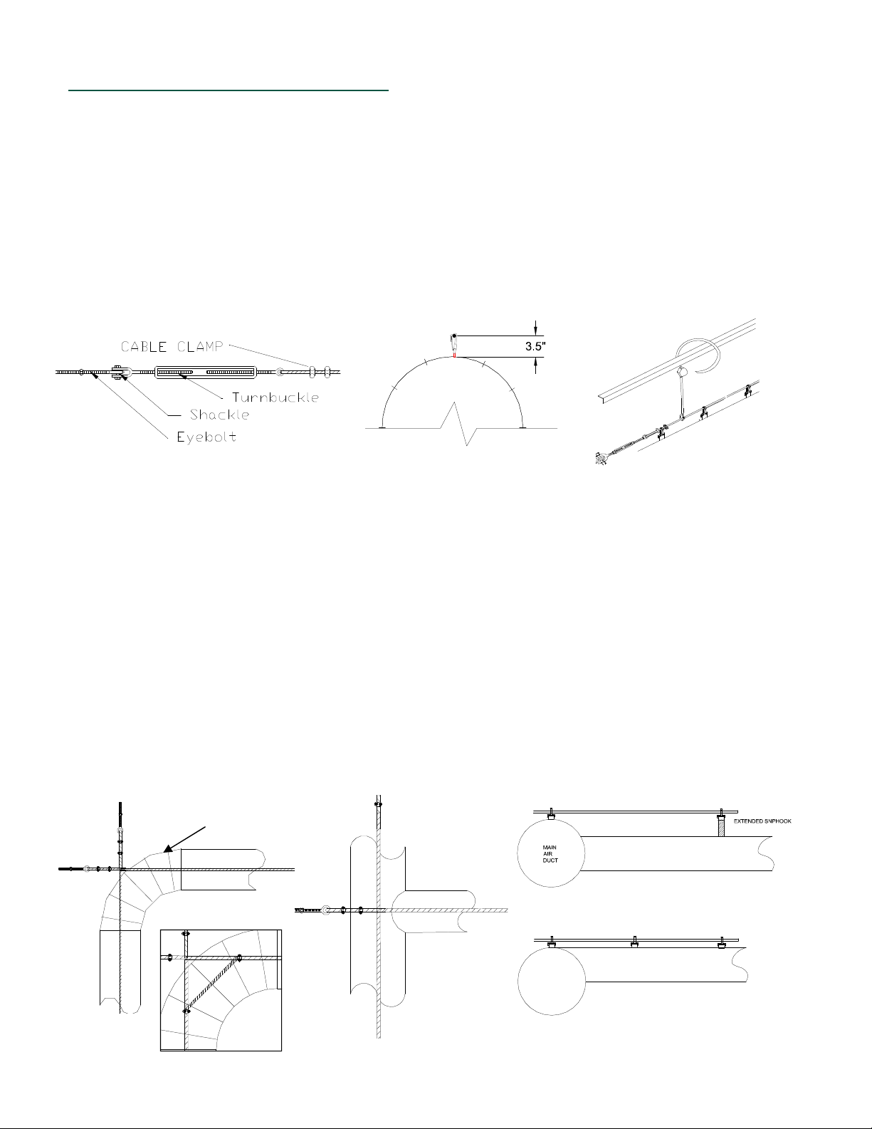
The cable supplied is .1875 dia. (7x7) aircraft cable, (vinyl coated or stainless cable may also be supplied). The orientation (12 o, clock ) suspension cable should be positioned 3.5” (standard) above the surface of the diffuser. If plastic or
stainless steel snap hooks are specified, position cable 3” above the surface of the diffuser. Cable must be aligned with
the centerline of the airflow. If diffuser bounces for the first 20’-30’ it is not anchored with the airflow. Move the end of the
cable. Locate and secure end points of the cable run with eyebolts at required locations. Install eyebolt to turnbuckle and
turnbuckle to cable and cable to eyebolt. Turnbuckle is used at one end to tighten cable.
General Note: one 1/2” x 6” turnbuckle for every 100’ of length
Multiple turnbuckles may be required. Vertical cable supports can be installed to prevent cable from sagging. Number of
supports depends on desired cable levelness. Vertical supports cannot be installed until diffuser has been hung and inflated. Cable tension can be estimated by the amount of sag of the cable over the length installed.
( See Cable Tension chart ,page 4)
CADDY
SPEED
LINK
ERICO
When fabric fittings are incorporated in your installation, align cables with the centerline of the system. All
cables should be installed at the same elevation.
When elbows are used in the system cable should be installed as indicated as above. It is recommended
to inflate system before suspending elbow. Make sure elbow is fully inflated without kinks. Then use cable to support the elbow from the snaphooks in the elbow seams to the suspension cable where needed to suspend elbow
when system is deflated. A cable can be installed with cable clamps from one cable to the other at a 45 degree
angle above elbow to help suspend elbow. Starting from where the seam of the elbow begins measure (.414)x
(radius of elbow) and clamp the cross cable. Then connect the cross cable to the cable perpendicular to first cable. It should be connected to that cable the same distance coming from the other end of the elbow. Use short
lengths of cable or “S” hooks to attach “O” rings to the cable.
When tee’s or take offs are used install cables as above. Install cable perpendicular to main cable to suspend branch runs. To insure proper alignment the main of the fabric system can be installed to the cable and the
air handler first. Then the cross cables perpendicular to the main can be installed to suspend the branch runs.
If the take off port is top even all snap hooks will be the same distance of the diffuser. If the take off port is centered on the side of the main, the snap hooks are normally extended the same level as the snap hooks of the
main duct. Fittings may have quick connect joints such as zippers to ease the installation and maintenance of the
system.
BEGINNING
ELBOW SEAM
Cross Cable Option
Page 3

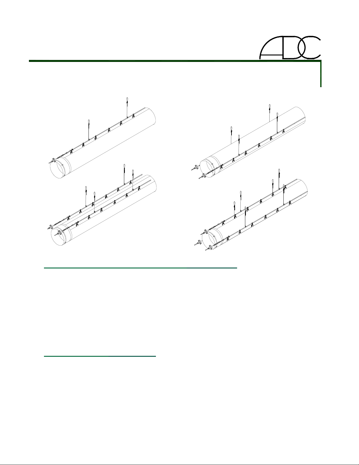
B) DOUBLE CABLE SUSPENSION
When installing a two cable suspension system, it is important to review the diffuser layout. It is important to
notice location of elbows, tees, or reductions. Improper placement of the cable may cause wear on the fabric.
Cable and turnbuckle installation are similar to single cable suspension systems. There are different variations of
double cable systems. Refer to the diagrams below. Snap hooks can be extended so that all cables will be at the
same elevation. Fittings may have quick connect joints such as zippers to ease the installation and maintenance
of the system. NOTE: 6:00 & 12:00 suspension is similar to 12:00 suspension with cable to cable distance the
same as 3 & 9:00 suspension. For Triple suspension use a combination of either 2:00, 10:00 with 12:00 or 3:00,
9:00 with 12:00
3:00 & 9:00 3:00 & 9:00 EXTENDED 2:00 & 10:00 2:00 & 10:00 EXTENDED
Note: The previous drawings illustrate possible double cable suspension systems. Some installations
may require cable support brackets. Since every installation is different, support brackets are not supplied. Triple
suspension systems used on larger diameters systems would be a combination of both single and double suspension guidelines.
Page 4

STEP THREE: INSTALLATION OF FABRIC DIFFUSER
When handling a diffuser prior and during installation, please keep anything that comes in contact with the diffuser
clean. If a diffuser is to be laid out on the floor, make sure floor is clean or something is laid down to protect diffuser
from dirt or debris on the ground that could catch on air jets and damage diffuser during installation.
1.) Attach the diffuser’s snap hooks to the cable.
2.) Pull diffuser down cable until fully extended.
3.) Pull open end of diffuser and slip over metal collar or metal duct (about 6-12”).
4.) install worm gear band around diffuser to secure it to metal duct.
Note: Worm gear bands are perforated and self taping screws can be used to help secure band and
keep from slipping. ( screws not included).
STEP FOUR: START UP
Turn on air handler and inflate diffuser. With the diffuser inflated, anchor the end cap or last snap hook of the
diffuser to the support cable as shown. This will keep the diffuser fully extended when diffuser is deflated and keep
the diffuser from sliding.
If the diffuser system flutters after installation, check to see if air handler is operating at its designed air volume
and static pressure. Fluttering can cause damage to fabric shortening life of system.
WARRANTY INFORMATION
Diffuser systems are subject to a five year limited warranty. The warranty covers workmanship and materials on all
components of the system. Only replacement costs and credits are covered. Cash payments are not available.
The warranty covers freight costs, but does not cover installation costs. The warranty excludes damage caused by
improper installation, failure to specify all system requirements and air handling equipment not performing as
specified. The effective start date of the warranty is the product ship date.
CABLE TENSION CHART ( AMOUNT OF SAG (in inches) BASED ON CABLE TENSION OF 500 LBS.)
LENGTH IN FEET
25 50 75 100 125 150 175 200 225 250 275 300
DIA."
12
18
20
24
30
36
38
42
48
52
56
62
68
74
76
84
0.35 1.41 3.17 5.63 8.80 12.67 17.25 22.53 28.51 35.20 42.59 50.68
0.49 1.97 4.44 7.89 12.33 17.76 24.17 31.57 39.96 49.33 59.69 71.03
0.54 2.16 4.86 8.65 13.51 19.45 26.48 34.58 43.77 54.04 65.39 77.81
0.63 2.54 5.71 10.15 15.86 22.84 31.09 40.61 51.40 63.46 76.78 91.38
0.78 3.10 6.98 12.41 19.40 27.93 38.02 49.66 62.85 77.59 93.88 111.73
0.92 3.67 8.25 14.67 22.93 33.02 44.94 58.70 74.29 91.72 110.98 132.07
0.96 3.86 8.68 15.43 24.11 34.71 47.25 61.71 78.11 96.43 116.68 138.86
1.06 4.23 9.53 16.94 26.46 38.11 51.87 67.74 85.74 105.85 128.08 152.42
1.20 4.80 10.80 19.20 29.99 43.19 58.79 76.79 97.18 119.98 145.17 172.77
1.29 5.18 11.65 20.70 32.35 46.58 63.40 82.81 104.81 129.40 156.57 186.33
1.39 5.55 12.49 22.21 34.70 49.97 68.02 88.84 112.44 138.82 167.97 199.90
1.53 6.12 13.77 24.47 38.24 55.06 74.94 97.89 123.89 152.95 185.07 220.24
1.67 6.68 15.04 26.73 41.77 60.15 81.87 106.93 135.33 167.08 202.16 240.59
1.81 7.25 16.31 28.99 45.30 65.23 88.79 115.97 146.78 181.21 219.26 260.94
1.86 7.44 16.73 29.75 46.48 66.93 91.10 118.99 150.59 185.92 224.96 267.72
2.05 8.19 18.43 32.76 51.19 73.71 100.33 131.04 165.85 204.76 247.76 294.85
EXAMPLE: 30” DIA. X 200 ft. diffuser would have a sag of about 50”. With one vertical support 100 ft. in the sag
is reduced to 12.41” and two supports at, (66 ft. & 132 ft.) would reduce the sag between supports to about 5”.
 Loading...