

Page 1
WorldDSL
TM
Exchange Office Management Unit
EMU-830 User Manual
Document Number:
LTPE-UM-3159-02
Page 2

REVISION HISTORY
The Revision History provides a summary of any changes in this manual. Please make sure you are using the
latest revision of this manual.
September 25, 2006
Revision Release Date Revisions Made
01 September 30, 2004 Initial release.
02 September 25, 2006 Technical update for L4A/L6A.
This manual is available online at ADC’s website (www.adc.com/documentationlibrary/) or you can order copies
of the manual by contacting your sales representative. Please ask for document LTPE-UM-3159-02.
Copyright
©2006 ADC Telecommunications, Inc. All rights reserved.
Trademark Information
ADC is a registered trademark of ADC Telecommunications, Inc. WorldDSL is a trademark of ADC Telecommunications,
Inc. No right, license, or interest to such trademarks is granted hereunder, and you agree that no such right, license, or
interest shall be asserted by you with respect to such trademarks.
Other product names mentioned in this document are used for identification purposes only and may be trademarks or registered trademarks of their respective companies.
Disclaimer of Liability
Information contained in this document is company private to ADC Telecommunications, Inc., and shall not be modified,
used, copied, reproduced or disclosed in whole or in part without the written consen t of ADC.
Contents herein are current as of the date of publication. ADC reserves the right to change the contents without prior notice.
In no event shall ADC be liable for any damages resulting from loss of data, loss of use, or loss of profits, and ADC further
disclaims any and all liability for indirect, incidental, special, consequential or other similar damages. This d isclaimer of
liability applies to all products, publications and services during and after the warranty period.
Page 3

Table of Contents
Chapter 1: Overview ....................................................................................................... 1-1
New Features ........................................................................................................................... 1-1
St an dard Features ....................................................................................................................1-1
Front Panel ...............................................................................................................................1-2
Major Components ................................................................................................................... 1-3
Multishelf TAO ..........................................................................................................................1-3
SNMP .......................................................................................................................................1-6
SNMP Management Information Base .................................................................................... 1-7
Traps ........................................................................................................................................ 1-8
BOOTP and TFTP Protocols .................................................................................................... 1-9
Xmodem Protocol ..................................................................................................................... 1-9
Alarms ....................................................................................................................................1-10
Autonomous Dial-out Alarm Reporting ..................................................................................1-10
External Shelf Clock Backup Circuit ........................................................................................1-11
Chapter 2: Installation .................................................................................................... 2-1
EMU Jumper Settings ..............................................................................................................2-1
EMU Installation .......................................................................................................................2-2
Multishelf Cable Connections ...................................................................................................2-4
Local Terminal Connections .....................................................................................................2-5
Remote Terminal and Local Shelf Modem Connections ..........................................................2-7
Management Station Internal Modem ................................................................................2-7
Management Station External Modem ............................................................................... 2-7
Local Shelf Modem for Multishelf TAO ............................................................................... 2-7
Shelf Modem for SLIP Operation .............................................................................................2-9
Chapter 3: Menu Navigation and Multishelf Configuration ........................................ 3-1
Console Menu Navigation ........................................................................................................3-1
Console Menu Options .............................................................................................................3-1
Multishelf Configuration ............................................................................................................ 3-3
Logging On ......................................................................................................................... 3-3
Network Screen .................................................................................................................. 3-4
Logging in to the Main menu .............................................................................................. 3-4
Main Menu ..........................................................................................................................3-4
Logging into DSL Circuits ................................................................................................... 3-7
Enabling or Disabling Alarm Reporting ..............................................................................3-8
Config Menu ....................................................................................................................... 3-8
Network Parameters Menu ................................................................................................ 3-8
SNMP Parameters Menu ..................................................................................................3-11
Modem Parameters (Configure and Test Dial-out Alarm Reporting) ...............................3-14
Shelf Alarms Menu ........................................................................................................... 3-16
Remote Alarm Reporting .................................................................................................. 3-17
Set Date and Time ........................................................................................................... 3-17
LTPE-UM-3159-02 iii
Page 4

Table of Contents September 25, 2006
Change Password ............................................................................................................ 3-18
Set Shelf ID ......................................................................................................................3-19
Terminal Settings ..............................................................................................................3-20
Set to Factory Defaults ..................................................................................................... 3-21
Reset EMU ....................................................................................................................... 3-22
Inventory Information Screen ........................................................................................... 3-22
Managing Firmware Through the Upload Menu .................................................................... 3-24
Appendix A: Specifications .........................................................................................A-1
Alarms ......................................................................................................................................A-1
Power Requirements ................................................................................................................A-1
Environmental ..........................................................................................................................A-1
Regulatory Approvals ...............................................................................................................A-1
Compatibility .............................................................................................................................A-1
Appendix B: Product Support .....................................................................................B-1
Glossary ......................................................................................................................GL-1
iv LTPE-UM-3159-02
Page 5

List of Figures
Figure 1-1. EMU-830 Front Panel .......................................................................................1-2
Figure 1-2. Local Management of a Single Shelf Using RS-232/Telnet .............................1-4
Figure 1-3. Remote Management of Multiple Shelves at T wo Si tes Using Multishelf TAO 1-4
Figure 1-4. Multishelf TAO Network Screen .......................................................................1-5
Figure 1-5. Multishelf TAO Main Menu Screen ...................................................................1-5
Figure 1-6. WorldDSL Shelves Managed by SNMP through LAN and SNMP
through SLIP .....................................................................................................1-7
Figure 1-7. EMU-830 Alarm Relay Diagram .....................................................................1-10
Figure 1-8. External Shelf Clock and EMU-830 List 6A Backup Circuit ........................... 1-11
Figure 2-1. Location of the SLIP Header Connector P6 on the EMU-830 ..........................2-1
Figure 2-2. Removing the EMU-Slot Faceplate from EMS-830 ..........................................2-2
Figure 2-3. Installing the EMU-830 into Slot 17 of EMS-830 ..............................................2-3
Figure 2-4. 10BASE-T Multishelf Cable Connections .........................................................2-4
Figure 2-5. EMU-830 Console Port Pinouts to DB-9 or DB-25 Connector .........................2-5
Figure 2-6. Connecting a Maintenance Terminal or PC to the EMU-830 Console Port ..... 2-6
Figure 2-7. Modem to EMU Serial Cable Pinouts ...............................................................2-9
Figure 2-8. Modem to SLIP Port Cable Pinouts ................................................................2-10
Figure 3-1. Logon Screen Dialog Box .................................................................................3-3
Figure 3-2. Network Screen ................................................................................................3-4
Figure 3-3. Main Menu Screen ...........................................................................................3-5
Figure 3-4. Config Menu .....................................................................................................3-8
Figure 3-5. Network Parameters Menu ...............................................................................3-9
Figure 3-6. SNMP Parameters Menu ............................................................................... 3-11
Figure 3-7. Modem Parameters Menu ..............................................................................3-14
Figure 3-8. LOSW* and LOSW1 Alarm Reporting Screen ...............................................3-15
Figure 3-9. LOS*, PFO* and LOSW* Alarm Reporting Screen ........................................3-16
Figure 3-10.Shelf Alarms Menu .........................................................................................3-16
Figure 3-11.Remote Alarm Reporting Menu Item ..............................................................3-17
Figure 3-12.Set Date/Time Dialog Box ..............................................................................3-18
Figure 3-13.Change Password Dialog Box .......................................................................3-19
Figure 3-14.Set Shelf ID Dialog Box ..................................................................................3-19
Figure 3-15.Terminal Settings Menu ..................................................................................3-20
Figure 3-16.Restore To Factory Defaults Warning Prompt ................................................3-21
Figure 3-17.Reset EMU Warning Prompt ..........................................................................3-22
Figure 3-18.Inventory Information Screen .........................................................................3-23
Figure 3-19.Upload Line Unit Menu Item ...........................................................................3-25
Figure 3-20.Upload to Line Unit Dialog Box ......................................................................3-25
LTPE-UM-3159-02 v
Page 6

List of Figures September 25, 2006
Figure 3-21.Xmodem Transfer Message ...........................................................................3-26
Figure 3-22.Local Line Unit Uploading Message ...............................................................3-26
Figure 3-23.Upload EMU Menu Item .................................................................................3-28
Figure 3-24.Upload to Local EMU Dialog Box ...................................................................3-28
Figure 3-25.TFTP Upload EMU Prompt ............................................................................3-29
Figure 3-26.Xmodem Upload EMU Prompt .......................................................................3-29
Figure 3-27.Boot Loader Prompt .......................................................................................3-30
Figure 3-28.Remote Upload EMU Dialog ..........................................................................3-30
Figure 3-29.Remote EMU Upload Message .....................................................................3-31
vi LTPE-UM-3159-02
Page 7

List of Tables
Table 1-1.EMU-830 List 4A and 6A Front Panel Components ................................... ........1-2
Table 1-2.W orldDSL Traps ..................................................................................................1-8
Table 3-1.Console Menu Navigation Keys ............................... ................ ................. ..........3-1
Table 3-2.Logon, Network, and Main Menu Screen Selections ..........................................3-2
Table 3-3.DSL Line Unit Status Conditions .........................................................................3-6
Table 3-4.DSL Circuit Alarms in Order of Severity ..............................................................3-6
Table 3-5.Network Parameters .........................................................................................3-10
Table 3-6.SNMP Parameters Menu ..................................................................................3-12
Table 3-7.Data in Inventory Information Screen ................................................................3-23
Table 3-8.Line Unit Uploads ..............................................................................................3-25
LTPE-UM-3159-02 vii
Page 8

List of Tables September 25, 2006
viii L TPE-UM-3159-02
Page 9
ABOUT THIS MANUAL
INTRODUCTION
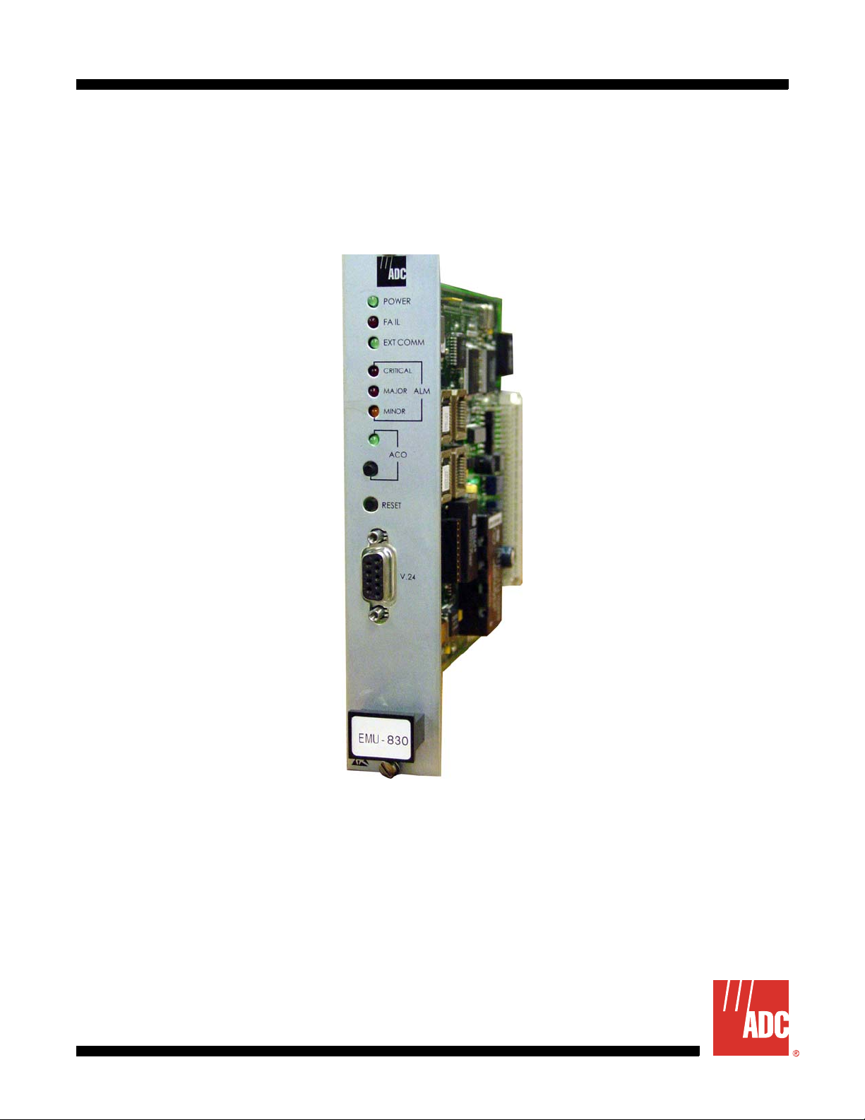
This manual contains information on the ADC® World DSL™ EMU-830 (hereafter referred to as the “EMU-830”). An
Exchange Office Management Unit (EMU) is installed in a WorldDSL Exchange Office Management Shelf (EMS).
The EMU provides alarm, fault, configuration, and performance management of HDSL and G.SHDSL circuits
deployed from a WorldDSL shelf.
ORGANIZATION
This manual includes the following chapters:
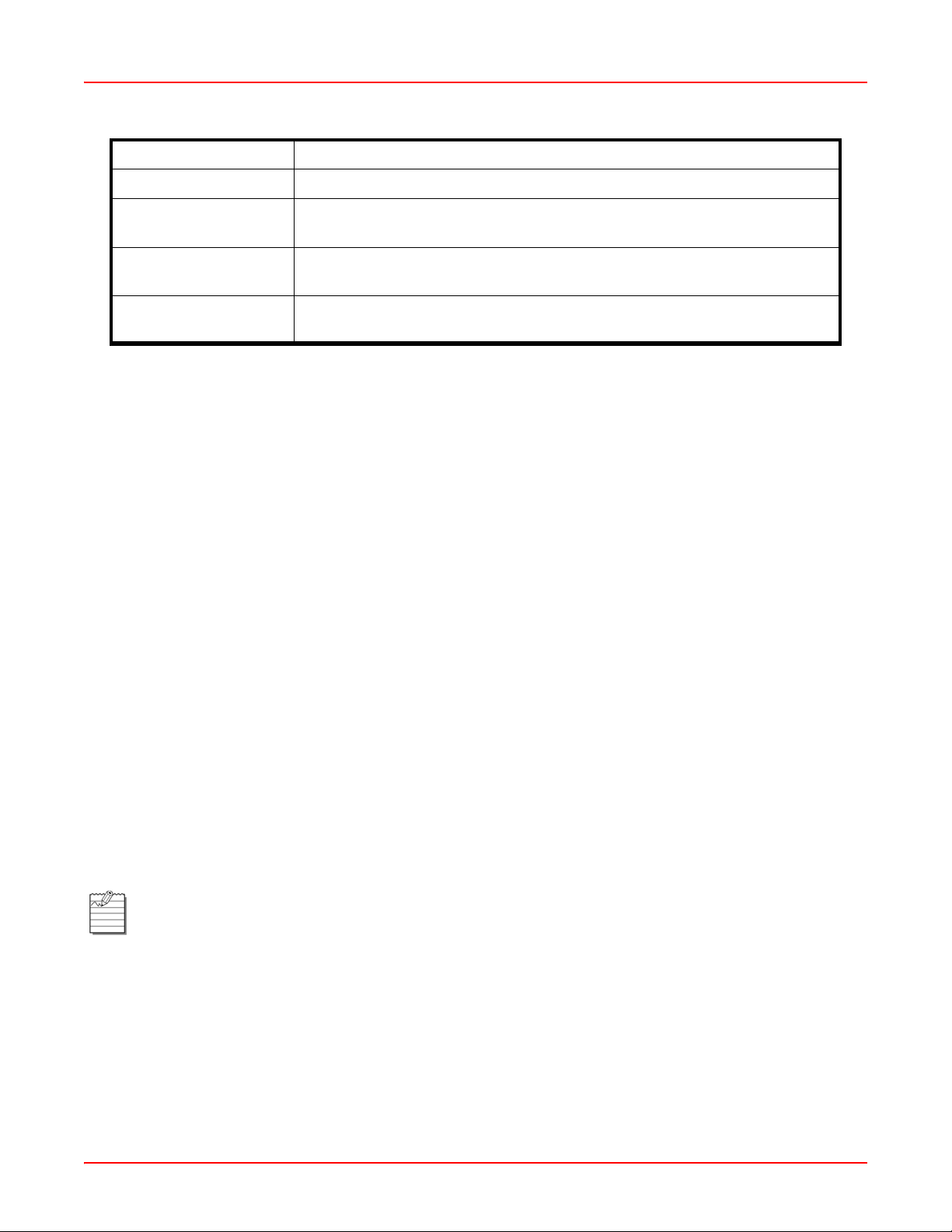
Chapter Description
Chapter 1: Overview Summarizes the features and functionality provided with the
EMU-830 management unit.
Chapter 2: Installation Provides procedures for installing the EMU-830 unit.
Chapter 3: Menu Navigation and Multishelf
Configuration
Appendix A: Specifications Summarizes alarm, power, and card compatibility requirements
Appendix B: Product Support Provides information on how to contact the ADC Technical
Glossary Defines abbreviations and acronyms for the ADC WorldDSL
Describes how to navigate management unit screens and
configure shelf, alarm, performance, and system settings.
for the EMU-830.
Support group.
product family.
INTENDED AUDIENCE
This manual is intended for anyone needing to install, operate, and maintain an ADC WorldDSL EMU-830.
CONVENTIONS
The following style conventions and terminology are used throughout this guide.
Element Meaning
Bold font Text that you must input exactly as shown (e.g., type 1 for card 1), menu buttons
(e.g., ACCEPT SHELF OPTIONS) or menu screen options (e.g., ALARMS screen) that
you must select
Italic font Variables that you must determine before inputting the correct value (e.g., Password )
Monospace font References to screen prompts (e.g., Invalid Password...Try Again:.)
Reader Alert Meaning
Alerts you to supplementary information
IMPORTANT
Alerts you to supplementary information that is essential to the completion of a task
!
LTPE-UM-3159-02 ix
Page 10
About This Manual September 25, 2006
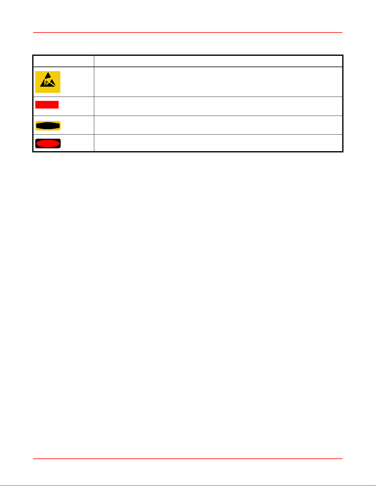
Reader Alert Meaning
Alerts you to possible equipment damage from electrostatic discharge
ATTENTION
CAUTION
WARNING
DANGER
Alerts you to possible data loss, service-affecting procedures, or other similar type
problems
Alerts you that failure to take or avoid a specific action might result in hardware damage or
loss of service
Alerts you that failure to take or avoid a specific action might result in personal harm
EU COMPLIANCE
This product has been CE marked in accordance with the requirements of European Directive 73/23/EEC; the
following mentioned product is in conformity with Low Voltage Directive 73/23/EEC in order to comply with the
requirements in the Council Directive 73/23/EEC relating to electrical equipment designed for use within certain
voltage limits and the Amendment Directive 93/68/EEC.
For safety evaluation of the compliance with this Directive 73/23/EEC, these standards were applied:
IEC 60950:1999, EN 60950:2000.
INSPECTING YOUR SHIPMENT
Upon receipt of the equipment:
• Unpack each container and visually inspect the contents for signs of damage. If the equipment has been damaged in transit, immediately report the extent of damage to the transportation company and to ADC. Order
replacement equipment, if necessary.
• Check the packing list to ensure complete and accurate shipment of each listed item. If the shipment is short
or irregular, contact ADC as described in Appendix B: “Product Support” on page B-1. If you must store the
equipment for a prolonged period, store the equipment in its original co ntainer.
x LTPE-UM-3159-02
Page 11

Chapter
OVERVIEW
The EMU-830 provides management for HDSL and G.SHDSL circuits using either of the following methods:
• One or more shelves of HDSL or G.SHDSL circuits can be managed by connecting a management terminal (or
PC with terminal emulation software) to the EMU-830 of one shelf. The management terminal (or PC) can be
connected to the EMU-830 either directly (or through modems over a dial-up network). When two or more
shelves are present, the Ethernet ports of each shelf can be interconnected to form a Local Area Network
(LAN). This method of management is referred to as Multishelf Terminal Access Option (Multishelf TAO).
• One or more shelves of HDSL or G.SHDSL circuits can be managed over a LAN using the Simple Network
Management Protocol (SNMP). SNMP can access a shelf through its 10BASE-T Ethernet port or through its
Serial Line Interface Port (SLIP) over dial-up modem connections. These methods of management are referred
to as SNMP through LAN and SNMP through SLIP. The StarGazer application can be used to manage
WorldDSL shelves with the EMU-830 using SNMP through LAN.
• Management of a single shelf or multshelf TAO using Telnet.
The EMU-830 List 4A and List 6A are CE marked.
NEW FEATURES
New features in this release include management of new V11 WD92xGx line cards.
1
Note: DSL is used throughout the remaining page s of th is document when referring to both HDSL and
G.SHDSL.
ST ANDARD FEATURES
St andard fea tur es of the EMU-830 in clud e:
• Support of Multishelf TAO
• Support of Point-to-Multipoint (PTM) application mode (HDSL)
• Support of Single-Pair application, Two Pair, 1+1 Application Modes (WD92xGx)
• Support of Telnet access for TAO over Ethernet or SLIP port
• Doubler support for two-pair line units (HDSL)
• Support of rate-selectable HDSL line and desktop units
• Universal Termination Units (UTUs) supported as a Line Termination Unit (LTU) or Network Termination Unit
(NTU) through SNMP (HDSL and G.SHDSL 1-pair)
• WorldDSL WD92xGx G.SHDSL 2-p air line cards (G.703, Nx64K, Ethernet) configurable as STU-C or STU-R
• User programmable baud rates for SLIP port
• Chassis slots & DSL loops identified in alarm report s
• Configuration changes automatically saved in NVRAM
• Automatic log out after 20 minutes of keyboard inactivity
• Backup timing circuit for external shelf clock on EMU-830 List 6A
• Firmware download protocol (TFTP, XModem)
• Trap s Gener atio n
LTPE-UM-3159-02 1-1
Page 12
Chapter 1: Overview September 25, 2006
t
FRONT PANEL
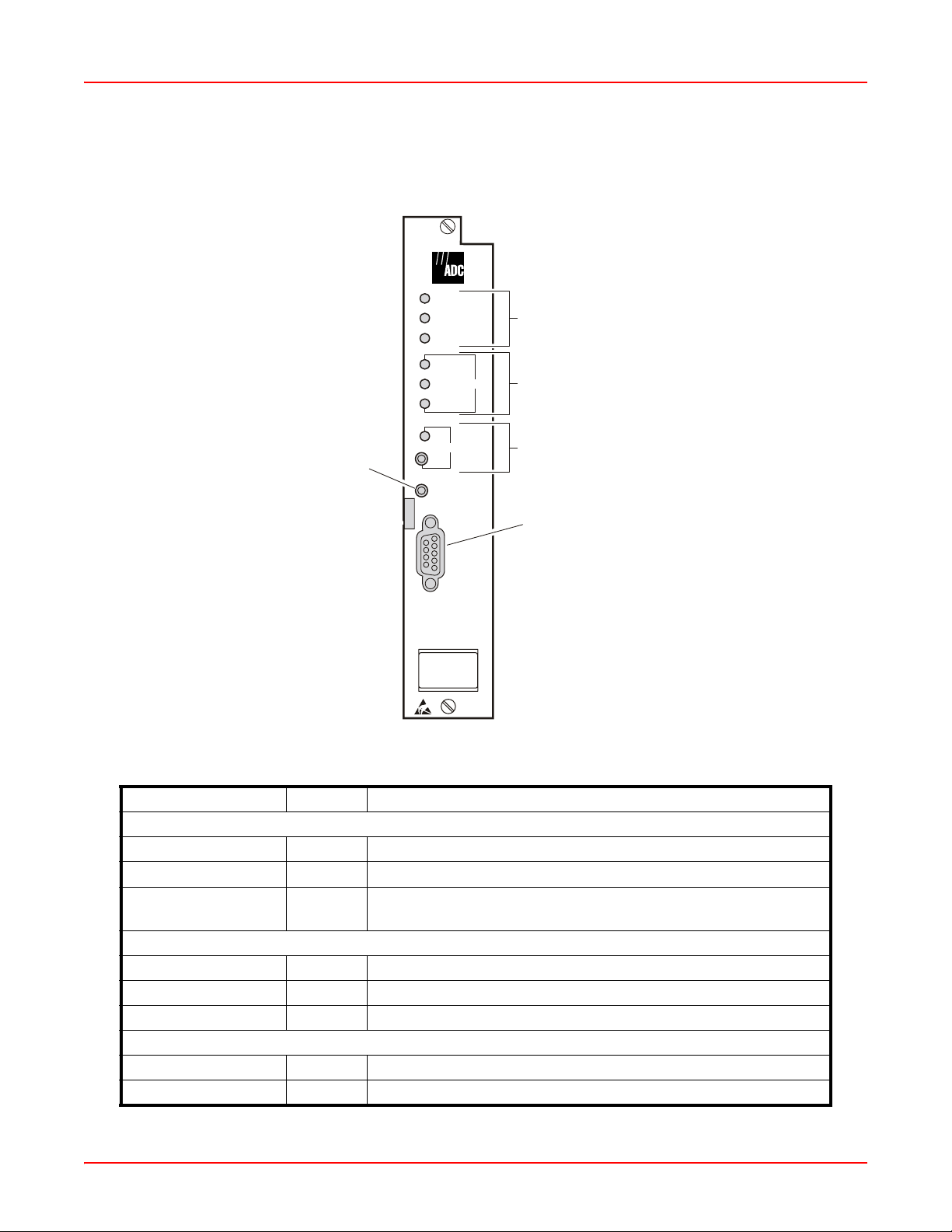
Figure 1-1 and Table 1-1 identify and describe the front-panel components of the EMU-830 Lists 4A and 6A.
POWER
FAIL
EXT COMM
CRITICAL
MAJOR
MINOR
ALM
System status LEDs
Alarm LEDs
Reset switch
ACO
RESET
V.24
EMU-830
Alarm cut-off LED
and switch
V.24 (RS-232) console por
Figure 1-1. EMU-830 Front Panel
Table 1-1. EMU-830 List 4A and 6A Front Panel Components
Name Mode Function
System Status LEDs:
Power Green Indicates power to the EMU-830.
Fail Red
Indicates system failure.
a
EXT Comm Green Indicates when data is being transmitted from the EMU-830
console port to a management station.
Alarm LEDs:
Critical ALM Red Indicates a critical alarm condition.
Major ALM Yellow Indicates a major alarm condition.
Minor ALM Yellow Indicates a minor alarm condition.
Alarm Cut-off LED and Switch:
ACO LED Green Indicates the Alarm Cut-Off (ACO) was activated.
ACO switch On/Off Activates ACO from the front panel if an alarm is active.
1-2 LTPE-UM-3159-02
Page 13

September 25, 2006 Chapter 1: Overview
Name Mode Function
Reset switch Resets the EMU-830 hardware.
V.24 (RS-232) console
port
a. It is normal for the Fail LED to illuminate briefly when power is applied to the EMU-830.
Provides access to EMU console menus either by local terminal
connected to console port via serial cable or by remote terminal
connected to console port via modems. Also supports
autonomous dial-out reporting of alarms to management station.
MAJOR COMPONENTS
Major components of the EMU-830 management unit include:
• 68302 processor
• 2 MB Flash RAM program memory
• Ethernet 10BASE-T port
• Asynchronous Serial Line Internet Protocol (SLIP) port (RS-232/RS-485)
• Front panel V.24 (RS-232) console port
• Audible and visual relays for critical, major, and minor alarms
• Backup timing circuit for external shelf clock (EMU-830 List 6A only)
The EMU-830 Flash RAM program memory permits firmware upgrades through TFTP or Xmodem downloads
(see “BOOTP and TFTP Protocols” on page 1-9 and “Xmodem Protocol” on page 1-9).
Note: A total or partial failure of the EMU-830 affects only the centralized management capabilities of the
system, it does not affect the DSL circuits deploye d in the shelf. In case of EMU-830 failure, the HDSL cards
can be managed directly from their front panel V.24 Craft port. To use the local management RS-232
interface of an HDSL card it is necessary to remove the EMU-830 from the shelf. To manage a G.SHDSL
card using an RS-232 interface, it is not required to remove the EMU-830 from the shelf.
MULTISHELF TAO
Multishelf TAO is supported through the EMU-830 front panel V.24 console port and provides an asynchronous,
maintenance terminal, auto-baud interface where you can:
• Monitor all shelf and DSL circuit alarms through a single common screen
• Communicate to a selected shelf and DSL card using the standard line unit console menus
• Set up network configuration parameters and SNMP parameters
• Configure the common equipment and shelf-wide alarms
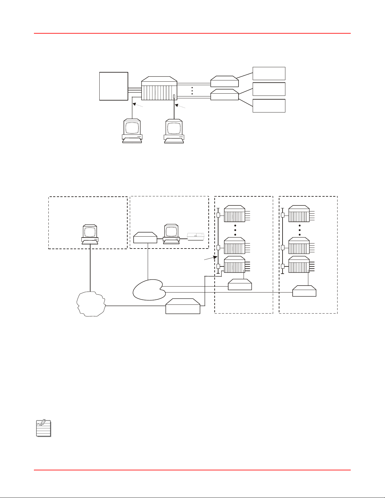
Figure 1-2 on page 1-4 illustrates local management of a single shelf using TAO. The shelf communicates with the
local terminal (or PC) through the EMU-830 V.24 console port. Figure 1-3 on page 1-4 illustrates remote
management of multiple shelves at two sites using Multishelf TAO. Up to 32 shelves at each site are connected over
a LAN. The IP address and subnet mask are configured to place all shelves at one site on the same subnet. Each
multishelf network communicates with the common network management station over the dial-up Public Switched
Telephone Network (PSTN).
Multishelf TAO is also supported using Telnet to 10BaseT port of an EMU-830.
LTPE-UM-3159-02 1-3
Page 14
Chapter 1: Overview September 25, 2006
Exchange
Switch
Figure 1-2. Local Management of a Single Shelf Using RS-232/Telnet
Network Management Station
PC running Telnet
Client/StarGazer
Ethernet
Network
WorldDSL
Shelf
To EMU
10Base-T
port
PC running
Telnet Client
Network Management Station
VT-100 dumb terminal
or PC with terminal
emulation software
Modem
PSTN
VT100 dumb
PC with terminal
emulation software
Up to 32 shelves linked
over Ethernet network
DSL Lines
terminal or
Ethernet Hub/
Switch
NTU/STU-R
NTU/STU-R
To EMU Console port
from PC serial port
Printer
EMU
10Base-T
Port
Modem connected to
console port of any EMU
Modem
GSM
Base Station
Video
Conference
PBX
DSL
Lines to
NTUs/
STU-Rs
DSL
Lines to
NTUs/
STU-Rs
DSL
Lines to
NTUs/
STU-Rs
Exchange Office 2Exchange Office 1
DSL
Lines to
NTUs/
STU-Rs
DSL
Lines to
NTUs/
STU-Rs
DSL
Lines to
NTUs/
STU-Rs
Modem
Modem connected to
console port of any EMU
Figure 1-3. Remote Management of Multiple Shelves at Two Sites Using Multishelf TAO
The Multishelf TAO firmware allows the DSL circuits in a single shelf or a network of shelves to be managed from a
single point-of-access (the EMU-830 console port of one shelf or using a Telnet session to one EMU-830). The
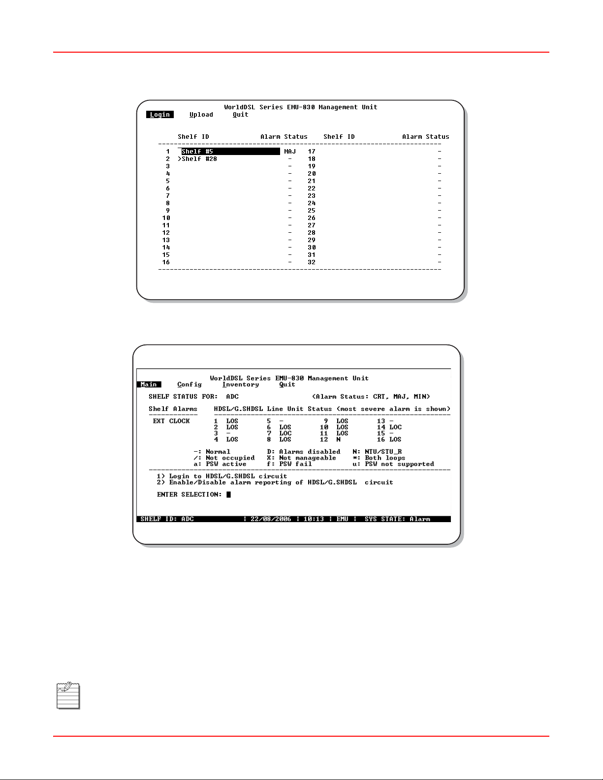
alarm status for each shelf in a multishelf network can be viewed on a single Network screen (Figure 1-4 on page 1-
5), and the alarm status of each DSL circuit in a selected shelf can be viewed on a single Main Menu screen (Figure
1-5 on page 1-5). Each EMU-830 constantly monitors the DSL cards in its shelf for alarm conditions and
automatically updates the alarm status.
From the T AO Network screen (Figure 1-4 on p age 1-5) , you can access any shelf in the network and then, from the
Main Menu screen (Figure 1-5 on page 1-5), log into any DSL card installed in the shelf. Logging into an DSL card
provides access to that card’s maintenance menus and is equivalent to connecting a terminal directly to the Craft
port on the HDSL card.
Note: HDSL cards cannot be directly managed from their front-panel craft port when the EMU-830 is
installed in the shelf. G .SHDSL (UTU-91x an d WD92xGx) cards can be managed from their front-p anel craft
port when the EMU-830 is installed in the shelf. Telnet can also be used to manage multiple EMU-830s
using multishelf TAO in the same lo gical IP networ k.
1-4 LTPE-UM-3159-02
Page 15
September 25, 2006 Chapter 1: Overview
Figure 1-4. Multishelf TAO Network Screen
Figure 1-5. Multishelf TAO Main Menu Screen
A multishelf network is created by connecting the local area network (LAN) to the 10BASE-T Ethernet connector
available on a shelf. Each shelf must have an EMU-830 management unit installed. A VT100 terminal (or PC) is
connected either locally or remotely (through modems), or through Telnet access to the console port of one EMU in
the network. The shelf containing this EMU is called the local shelf. The local shelf coordinates communication with
all other shelves in the network, which are called the remote shelves.
It is not necessary for you to explicitly identify each shelf in the netwo rk, as the local she lf automatically discovers
them. You must, however, pre-configure the EMU in each shelf with a unique IP address and subnet mask to place
all the shelves on the same subnet.
Note: Shelf networks cannot be connected through a router because the local shelf uses UDP-broadcast
messages as a mechanism to automatically discover other shelves in the network, and routers generally
filter these broadcasts. For connecting multiple devices, use an Ethernet hub or switch instead.
LTPE-UM-3159-02 1-5
Page 16

Chapter 1: Overview September 25, 2006
In a remotely managed configuration, an external modem must be connected to the EMU-830 front panel V.24
(RS-232) console port. If enabled, alarm conditions cause ASCII messages to be transmitte d autonomously over the
dial-up network. These messages can be displayed on a monitor or sent directly to a printer. This provides the
network operator immediate notification of problems. The operator can then initiate a remote TAO session with the
local shelf to further diagnose and correct the problem.
The EMU-830 and the DSL card firmware can be easily upgraded using the Upload utility from the T AO Main menu.
This utility uses TFTP and Xmodem protocols.
A proprietary software download protocol per mits firmware to be downloaded to any unit (EMU or DSL line card) in a
multishelf T AO network. This protocol is supported by a special ADC a pplication program tha t can run on a PC. The
PC connects to the front panel RS-232 V.24 console port of one of the EMUs in the network.
Note: The Multishelf T AO firmware and SNMP age nt are factory loaded on all EMU-830 management units.
SNMP
SNMP (Simple Network Management Protocol) is an application layer protocol of the Internet suite of proto cols,
commonly referred to as TCP/IP (after the two core protocols⎯Transmission Control Protocol and Internet
Protocol), and is designed to be an "open" (non-proprietary) network management technolog y capa ble of managing
internetworking equipment from multiple vendors. SNMP is formally specified in a series of related RFC (Request
For Comment) documents from the Internet Engineering Task Force (IETF). The WorldDSL EMU-830 implements
SNMP version 1. Communications standards supported in Version 1 of the SNMP standard include IP, User
Datagram Protocol (UDP), Internet Control Message Protocol (ICMP), and Address Resolution Proto col (ARP). T wo
other protocols, Boot Protocol (BOOTP) and Trivial File Transfer Protocol (TFTP), are also included to support IP
address management and download of EMU-830 code over the network.
In an SNMP managed network, each WorldDSL shelf is considered a managed node and contains an SNMP
software agent that resides in the EMU-830. The software agent pro vides the operating kernel, SNMP protocols,
transport protocols, and management information. Multiple shelves, each of which deploy up to 16 DSL links, can be
centrally managed from a single SNMP-based Network Management Station. Each DSL link consists of an LTU/
STU-C unit installed in the shelf, a remote NTU/STU-R unit, and possibly one or two mid-span doublers. Doublers
are currently supported only with HDSL (e.g., LTU-804, UTU-804) line cards. A link is managed as one DSL system
by SNMP.
SNMP access is provided over two types of interfaces:
• SNMP through LAN. An interface using an Ethernet port (10BASE-T) on the WorldDSL shelf that supports
UDP over IP.
• SNMP through SLIP. An out-of-band (or dial-up) serial interface using the RS-232/RS-485 configurable SLIP
port on the WorldDSL shelf, which supports IP over a SLIP at a maximum 19.2k baud rate.
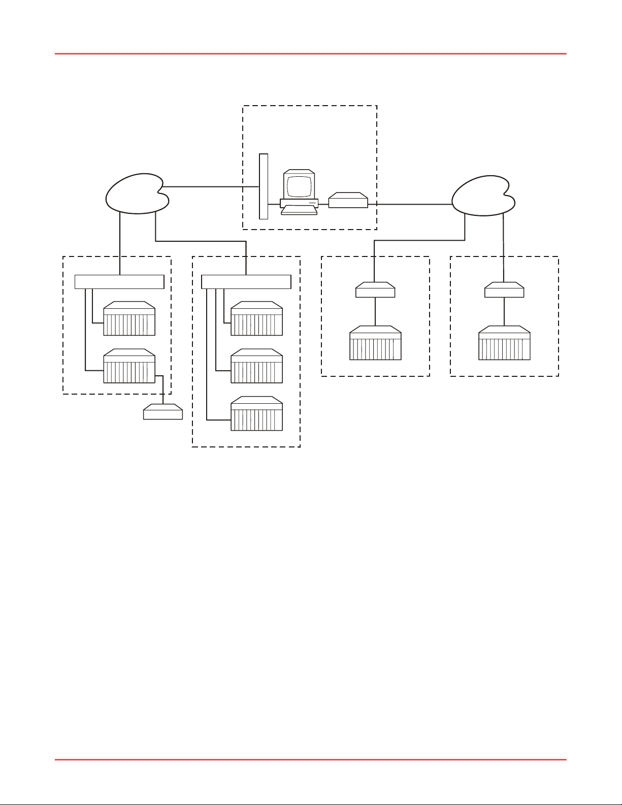
The network of WorldDSL shelves can be managed by one or more SNMP management stations at the same time
over either of the SNMP interfaces. Management can be performed through the 10BASE-T Ethernet port and the
RS-232/RS-485 SLIP port simultaneously. StarGazer manages WorldDSL shelves using SNMP through LAN.
Figure 1-6 on page 1-7 shows a network of WorldDSL shelves managed by SNMP through LAN and SNMP
through SLIP.
STU-C and STU-R terminology is used with the G.SHDSL WD92xGx line cards.
1-6 LTPE-UM-3159-02
Page 17
September 25, 2006 Chapter 1: Overview
Network Management Station
Unix workstation or PC running SNMP
Management Station software/StarGazer
Ethernet LAN
Ethernet
Network
SNMP
via
LAN
Site #1
Ethernet LAN
WorldDSL Shelf
WorldDSL Shelf
NTU/STU-R
Managed DSL
link
Site #2
Ethernet LAN
WorldDSL Shelf
WorldDSL Shelf
WorldDSL Shelf
Figure 1-6. WorldDSL Shelves Managed by SNMP through LAN and SNMP through SLIP
SNMP MANAGEMENT INFORMATION BASE
Modem
Site #3
WorldDSL Shelf
Modem
RS-232/485
SLIP Port
PSTN
SNMP
SLIP
Site #3
via
Modem
RS-232/485
SLIP Port
WorldDSL Shelf
Simple Network Manage Protocol (SNMP) specifies how to send information between a network management
station and managed devices on a network. Managed devices run a program called an agent. The agent interprets
SNMP requests and responds to them. The management station communicates with the agents in the managed
devices to:
• set configurations
• read configurations
• read status parameters
Management Information Bases (MIBs) define these configurations and status parameters. The Internet
Engineering Task Force (IETF) specifies standard MIBs for certain types of devices, ensuring any generic SNMP
application can manage them. Other vendor-specific MIBs such as those used by ADC, define the configuration,
status, trap, and performance parameters unique to the WorldDSL product line.
The EMU-830 performs as a proxy agent when managing line units. Each managed device has configuration,
status, and statistical information that defines its functionality and operation capabilities.
There are a total of six MIB files that define the SNMP management interface of the ADC W orldDSL pr oduct. These
files should be copied into the Network Manager Client MIB Subdirectory. Once copied onto the desired drive they
can be easily accessed by the Network Manager’s MIB compiler. The six MIB files are named as follows:
LTPE-UM-3159-02 1-7
Page 18

Chapter 1: Overview September 25, 2006
IMPORTANT
!
• RFC 1213 MIB II. The Internet-standard MIB for network management of TCP/IP-based internets. It defines
objects common to all devices that support SNMP. This includes objects related to generic configuration such
as the device's name (sysName), objects related to the transport protocols (IP, TCP, ICMP, etc.), and a description of the chassis' interface ports (data p orts as well as HDSL ports).
• pgmibhd.mib (Common MIB). An enterprise MIB (that is, unique to ADC products) that defines the top-level
branch structure for all ADC products including the W or ldDSL pro duct lin e.
• pgetsi.mib (ETSI Interface MIB). Enterprise MIB containing management objects for the shelf common equipment (chassis and EMU-830) and DSL circuit elements (LTUs/STU-Cs, NTUs/STU-Rs, doublers), excluding
DSL performance related objects which are contain ed in the DSL MIB. Examples include the EMU-830 LED status (emuLedSt atus), an LTU/STU-C V.35 port data rate (ltuDataPrtTimeSlots), and PTM managed items.
• pghdsl.mib (DSL MIB). Enterprise MIB containing objects related to the
performance of the DSL links, such as 15-minute and 24-hour performance history.
• pgagtmib.mib (SNMP Agent MIB). MIB containing management objects to control and configure the operation
of the IP and SNMP parameters. Examples include the EMU IP address, boot and image mode, and trap
receiver setup.
• pgetsitr.mib (ETSI SNMP Trap MIB). MIB containing a subset of the RFC 1215 common traps as well as ADC
enterprise traps (see “Traps” below for details).
These MIB files must be used with the management unit software release.
TRAPS
Traps are autonom ous, inter rup t-d rive n messages sent from a managed node (shelf) to a management station to
indicate the occurrence of an extraordinary event (such as alarms or a link going down) or a configuration change
(such as changes in alarm severity settings, circuit IDs, or loopback modes). When an eve nt occurs, the shelf sends
a trap to the management station, which polls the shelf to determine the nature of the event. Circuit Name is also
included in the trap.
A managed node (shelf) can be configured to send trap s to up to three trap receiver s (that is, management stations).
The WorldDSL traps are listed in Table 1-2.
T a ble 1-2 . W orldDSL Traps
Traps Definition
Cold Start MIB II standard trap indicating that the EMU-830 has come on-line.
Authentication failure MIB II standard trap indicating that the agent received an SNMP message with
an improper community string. For example, an SNMP-managed device
assigned to the community “ETSI” receives a message for a device in the
“HGIS” community.
Link up/link down MIB II standard trap indicating a loss of signal condition at one of the
transmission interfaces (E1 or DSL).
DSL circuit alarm ADC enterprise trap sent at the occurrence of an alarm condition on an DSL
circuit if that alarm is of a greater severity than any existing alarms on the
same circuit. Separate trap messages are sent for each DSL circuit in
the shelf.
1-8 LTPE-UM-3159-02
Page 19
September 25, 2006 Chapter 1: Overview
Traps Definition
Power supply failure Enterprise trap that indicates the failure of a -48 V shelf power supply input.
Multiple DSL loops down Enterprise trap used to indicate when the programmable threshold of the
number of downed DSL loops in the shelf has been exceeded.
System configuration
change
Line unit configuration
change
Enterprise trap that signals when a change has occurred in the physical
configuration of the system, such as the insertion or removal of LTUs/STU-Cs.
Enterprise trap that signals when a change has occurred in the configur ation of
a line unit (includes alarm severity settings, circuit IDs, and loopback modes).
BOOTP AND TFTP PROTOCOLS
BOOTP is a UDP/IP-based protocol that allows the EMU-830 to configure itself dynamically without supervision.
BOOTP provides a means for the EMU-830 to learn its protocol configuration, including:
• Local IP address and subnet mask
• Boot Server IP address
• Name of image file to be loaded into memory and executed
• Default router addresses
The BOOTP and TFTP protocols included with the EMU agent software facilitate these methods of software loading
and network configuration.
The EMU can be configured to learn its protocol configuration at reset from the network (by sending a BOOTP
broadcast message that is recognized by the BOOTP server) or from the NVRAM on the EMU. BOOTP provides a
simple means of unit configuration. It also allows the network administrator to dynamically allocate the IP address for
the EMU.
The EMU can also be configured to know where it should get its operational code (image file): either from the
BOOTP server using TFTP or from the flash RAM on the EMU. This allows the EMU to always download the most
recent image file at power-on or reset, and it lets the netw ork administrator keep the image file in a sing le location for
use by all the WorldDSL shelves.
XMODEM PROTOCOL
The Xmodem protocol permits software to be downloaded to any EMU or line unit (local or remote) from a PC
connected to the EMU front panel V.24 (RS-232) console port.
Associated Upload menus and screens allow selection of any shelf in the network and the EMU o r any line unit in
the shelf as the upload target.
The EMU and each line unit is reset and runs the new code following the software download.
Do not abort the download procedure when an XModem transfer is in progress.
LTPE-UM-3159-02 1-9
Page 20
Chapter 1: Overview September 25, 2006
ALARMS
The EMU-830 constantly monitors each of the DSL cards for alarm conditions. When so configured, the EMU-830
provides autonomous dial-out reporting of alarms to remote management stations and printers (see “Autonomous
Dial-out Alarm Reporting” on page 1-10). The EMU-830 List 6A monitors the external 2 MHz clock supplied to the
shelf (see “External Shelf Clock Backup Circuit” on page 1-11).
The alarm status is reported in several ways: alar m LEDs, alarm relays, terminal scree ns, SNMP trap s, and dial-out
reporting. DSL card alarms can be specified as major, minor, or disabled. Shelf alarms can be specified as major,
minor, critical, or disabled. A major alarm is asserted when an alarm condition occurs in a card or shelf tha t is
specified as major. A minor alarm is asserted when an alarm condition occurs in an DSL card or shelf that is
specified as minor. Only shelf alarms can be classified as critical. A critical alarm is asserted when any shelf alarm
occurs that is specified as critical. Use the TAO Main menu to login to an DSL circuit to configure the DSL card
alarms (see “Config Menu” on page 3-8).
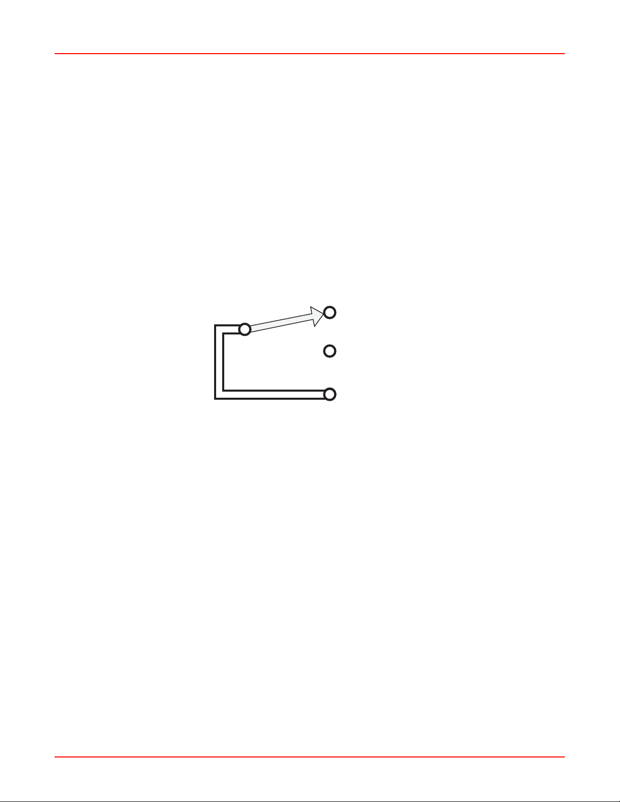
Six alarm relays are provided for use with external alarm indicators such as lights or buzzers. Each relay is a form C
type which provides three contacts: Common, Normally Open, and Normally Closed. An alarm relay diagram is
shown in Figure 1-7.
Normally Closed
Normally Open
Common
Figure 1-7. EMU-830 Alarm Relay Diagram
The six alarm relays are:
1. Critical Visual
2. Critical Audible
3. Major Visual
4. Major Audible
5. Minor Visual
6. Minor Audible
Additionally, a System ID relay is activated when any minor, major, or critical alarm is active in the shelf.
The Critical Visual and Critical Audible alarm relays and the System ID relay operate in the fail-safe mode. That is,
when power is lost to the EMU-830, the Common contact connects to the Normally Open contact.
The ACO (Alarm Cut-Off) function is used to retire active alarms by resetting the minor, major, and critical alarm
relays (both visual and audible). The Shelf Alarms menu (pageC-16) can be used to program which alarm relays
will and will not be retired when ACO is engaged. ACO can be activated by pressing the front panel ACO switch or
by connecting the external ACO input (pin 25 of the Alarm connector on a shel f) to ground. ACO is deactivated when
there are no alarms or when a new alarm occurs.
AUTONOMOUS DIAL-OUT ALARM REPORTING
When connected through a modem to a dedicated telephone line, the EMU-830 can dial-out to a remote
management station or printer to autonomously re port DSL card a nd shelf alar ms. For the EMU-830 to p erform this
function, you must first configure the EMU Modem Parameters, set the severity of the Shelf Alarms, and enable the
Remote Alarm Reporting option (see page C-14 through page C-17).
1-10 L TPE-UM-3159-02
Page 21
September 25, 2006 Chapter 1: Overview
E
l
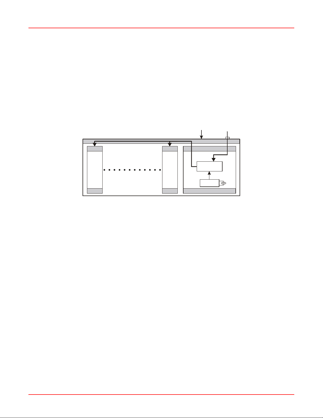
EXTERNAL SHELF CLOCK BACKUP CIRCUIT
The EMU-830 List 6A includes a backup circuit for the 2.048 MHz external shelf clock. This circuit will continue to
provide a 2.048 MHz clock to the DSL cards in the event the 2.048 MHz external shelf clock is lost. The software
reports the status of this circuit and allows the user to set th e seve rity of the alar m ge nerated when the clock is lost.
A block diagram of the clock backup circuit is shown in Figure 1-8 on page 1-11.
Under normal operation the external shelf clock and the backup circuit synchronize their respective clocks through
the EMUs phase-locked loop (PLL) device. In the event the external shelf clock is lost, the oscillator in the backup
circuit will continue to supply the 2.048 MHz clock. A Loss of External Clock alarm is reported to the management
station.
xterna
Backplane
EMS-83x Shelf
Clock
input
Slot 1 Slot 16
LTU/STU-C
LTU/STU-C
Slot 17
Reference
PLL
2.048 MHz
Source
Oscillator
EMU-830 List 6
Figure 1-8. External Shelf Clock and EMU-830 List 6A Backup Circuit
LTPE-UM-3159-02 1-11
Page 22

Chapter 1: Overview September 25, 2006
1-12 L TPE-UM-3159-02
Page 23
Chapter
2
INSTALLATION
This section describes the procedures for installing the EMU-830.
Note: Each shelf in a Multishelf TAO network must have an EMU-83 0 management unit inst alled.
Inserting and removing the EMU-830 from a shelf will not affect the operation of the DSL cards installed in
the shelf.
An EMU-830 failure will not affect the operation of the DSL cards installed in the shelf.
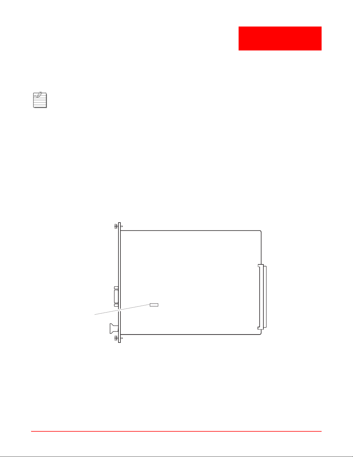
EMU JUMPER SETTINGS
EMU-830s are jumper configurable for an RS-232 or RS- 485 SLIP port interface. EMUs have an RS-232 factory
setting.
If you use the SLIP port to manage a shelf or shelves, you must configure the SLIP port interface before installing
the EMU-830. Do one of the following:
• For an RS-232 SLIP port interface, install the jumper on two-pin header connector P6 (Figure 2-1). This is the
factory default setting. Set the SLIP port baud rate as instructed in “Configure SNMP Operation Over SLIP” on
page 3-10.
• For an RS-485 SLIP port interface, remove the jumper from two-pin header connector P6 (Figure 2-1). Set the
SLIP port baud rate as instructed in “Configure SNMP Operation Over SLIP” on page 3-10.
RS-232
P6
Figure 2-1. Location of the SLIP Header Connector P6 on the EMU-830
LTPE-UM-3159-02 2-1
Page 24

Chapter 2: Installation September 25, 2006
EMU INSTALLATION
Install the EMU-830 in an EMS-830 as follows:
Step Action
1 Use a flat-blade screwdriver to loosen the two screws holding the EMU slot faceplate (Slot 17) in place,
then remove the slot faceplate (Figure 2-2).
EMS-830 shelf
EMU slot faceplate
Figure 2-2. Removing the EMU-Slot Faceplate from EMS-830
2-2 LTPE-UM-3159-02
Page 25

September 25, 2006 Chapter 2: Installation
Step Action
2 Align the EMU-830 card with the card guides at the top and bottom edges of Slot 17, then push the card
in until the EMU-830 front panel is flush with the front of the shelf (Figure2-3). The connector positions in
slots 1 through 16 prevent the EMU-830 from being installed in the wrong slot.
EMS-830 shelf
EMU-830
Figure 2-3. Installing the EMU-830 into Slot 17 of EMS-830
3 Tighten the two captive retaining screws on the front of the EMU-830 card.
LTPE-UM-3159-02 2-3
Page 26

Chapter 2: Installation September 25, 2006
J-45 cable
MULTISHELF CABLE CONNECTIONS
Note: Multishelf networks cannot be connected through a router because the local shelf uses UDP-
broadcast messages as a mechanism to automatically discover other shelves in the network, and routers
generally filter these broadcasts. A multishelf network is limited to 32 shelves.
To connect the shelves using the 10BASE-T Ethernet connectors (Figure 2-4):
Step Action
1 Plug an RJ-45 cable into the 10BASE-T connector at the rear of each shelf.
2 Plug the other end of the RJ-45 cables into the hub/switch connecting the shelves.
Note: The length of each RJ-45 cable cannot exceed 100 meters (328 feet).
Hub/Switch
WorldDSL
shelves
10BASE-T
connector
R
Figure 2-4. 10BASE-T Multishelf Cable Connections
2-4 LTPE-UM-3159-02
Page 27

September 25, 2006 Chapter 2: Installation
C
LOCAL TERMINAL CONNECTIONS
The console port of the EMU-830 in the local shelf can be connected directly to a VT100 terminal (or PC). Once
connected, you can use the terminal (or PC) to access the EMU-830 console menus. The console menus allow you
to configure each EMU and DSL circuit in a multishelf network, monitor and test system performance, and display
the inventory of installed DSL units.
The EMU-830 console port in the local shelf can be connected to the DB-9 or DB-25 serial port of a maintenance
terminal or PC. The EMU-830 console port pinouts and the required connections to a DB-9 or DB-25 serial port are
shown in Figure 2-5.
Note: For security purposes, if at any time during a TAO session the EMU-830 DTR input signal is lost, the
session automatically terminates.
Terminal or PC
DB-9 connector
(DTE)
Terminal or P
DB-25 connector
(DTE)
EMU-830
console port
DB-9 connector
(DCE)
6
4
3
2
6
4
3
2
5
DSR (Data Set Ready)
DTR (Data Terminal Ready )
TD (Transmit Data)
Rd (Receive Data)
GND
5
6
20
3
2
7
Figure 2-5. EMU-830 Console Port Pinouts to DB-9 or DB-25 Connector
LTPE-UM-3159-02 2-5
Page 28
Chapter 2: Installation September 25, 2006
Step Action
1 Connect a serial cable from the DB-9 or DB-25 serial port on the maintenance terminal or PC to the
V.24 (RS-232) console port on the EMU front panel (Figure 2-6).
Maintenance terminal or
PC with terminal emulation
program
DB-9 or DB-25
serial port
EMU-830
RS-232 cable
V.24 console port
Figure 2-6. Connecting a Maintenance Terminal or PC to the EMU-830 Console Port
2 Configure the maintenance terminal (or PC) for the following communication settings:
• 1200 to 19200 baud (19200 baud is recommended)
•No parity
• 8 data bits
• 1 stop bit
• Flow Control to None
• VT100 Emulation, or ANSI if VT100 is not available
• If your terminal supports a modem initialization string, it should be cleared
Note: If using a PC with the Microsoft Windows terminal emulation program, you must deselect both the
Show Scroll Bars option and the Use Function, Arrow, and Ctrl Keys for Windows option in the Terminal
Preferences menu (choose Settings | Terminal Preferences to access the Terminal Preferences menu).
2-6 LTPE-UM-3159-02
Page 29

September 25, 2006 Chapter 2: Installation
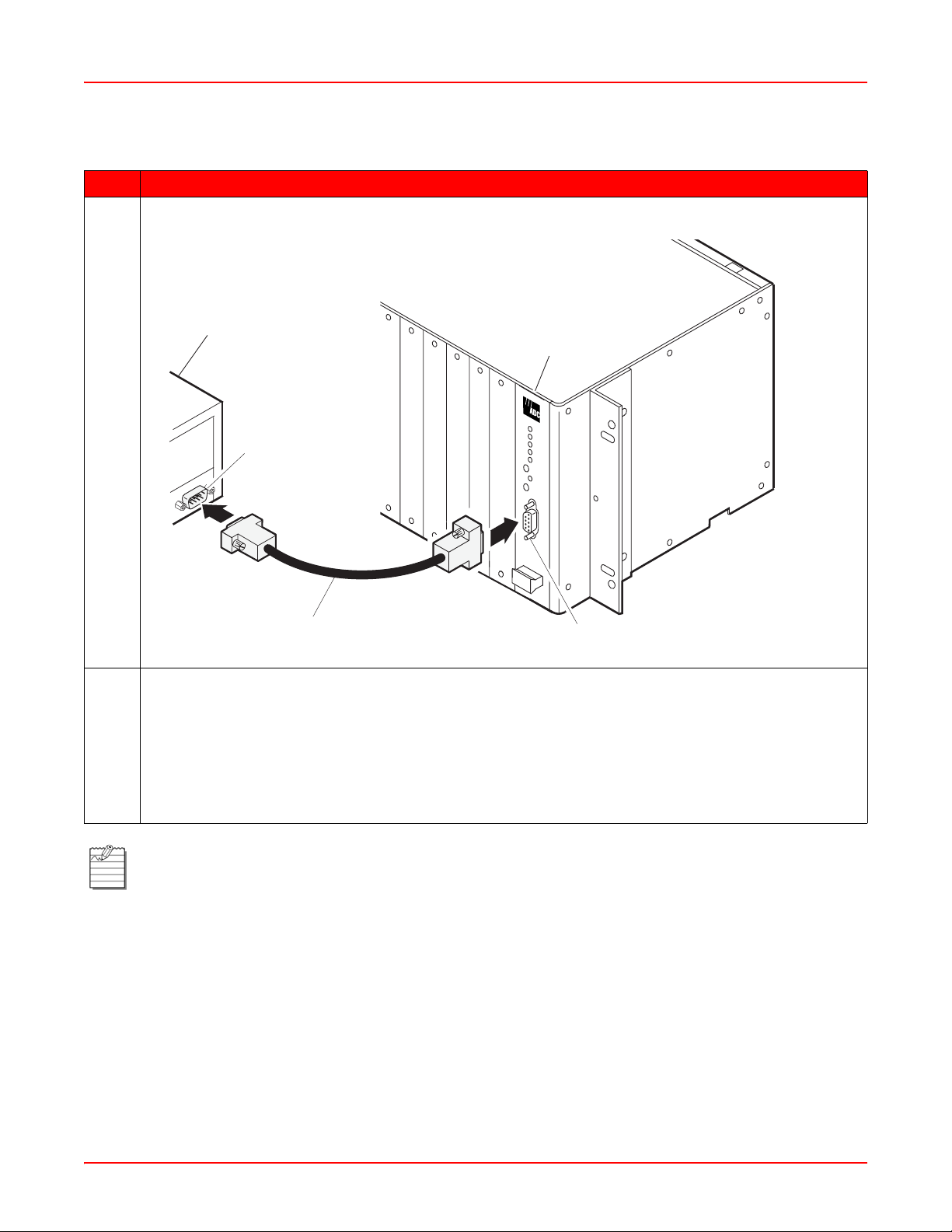
REMOTE TERMINAL AND LOCAL SHELF MODEM CONNECTIONS
Remote management of one or more Multishelf TAO sites over a telephone network requires the connection of a
modem to the remote management station and to the EMU residing in the local shelf of each site. Once connected,
the remote management station can access the console menus of one or more multishelf networks to configure,
monitor , and test their EMU and DSL circuits. The local shelf can autonomously report alarms to the management
station through the modem attached to its EMU.
Management Station Internal Modem
An internal modem card provides an RJ-11 jack at the back panel of the management station. If the management
station has an internal modem, plug your phone-line connector into the RJ-11 jack and turn on the management
station. Set up the internal modem for 19,200 baud. If you experience problems, refer to your modem or
management station user manual.
Management Station External Modem
An external modem requires a serial cable, an external power source, and an unused serial port on the back of the
management station.
To connect an external modem to your management station serial port:
Step Action
1 Plug a serial cable into an available serial port on the back of the management station, using a 9-to-25 pin
converter or gender changer if necessary.
2 Plug the other end of the cable into the serial port on the back of the modem.
3 At the back of the modem, plug the telephone line into the RJ-11 port labeled "LINE" or "TELCO".
4 Plug the modem into an external power source and turn it on, then turn on the management station.
5 Verify that the modem is responding to commands from the management station . Use a communications
program to send an AT command to the modem. The modem resp onds with the string "OK" if operation is
successful.
6 Configure the shelf modem for remote alarm reporting as instructed in “Remote Alarm Reporting” on
page 3-17.
7 If you experience problems refer to the modem or management station user manual.
Local Shelf Modem for Multishelf TAO
The local shelf in a remotely managed Multishelf TAO network uses an external modem connected to its EMU
console port. The modem, however, must be programmed with a PC before it can be connected to the EMU (the
EMU residing in the shelf cannot control a modem as a PC can).
Note: The shelf modem can be attached to the EMU in any sh elf. The shelf with the modem att ached is the
“local” shelf. If managing a shelf through its SLIP port, see “Shelf Modem for SLIP Operation” on p age 2-9.
LTPE-UM-3159-02 2-7
Page 30

Chapter 2: Installation September 25, 2006
Step Action
1 Connect the shelf modem to the PC and verify that it is in working condition as described in the preceding
section, “Management Station External Modem.”
2 Use a communications program to send the following initialization string to the modem:
AT&F
This string resets the modem to its original factory configuration and clears any previous programming
that can conflict with the communication between the modem and the EMU.
3 Send the following configuration string to the modem:
ATE0Q1S0=1&K0Y0&W0
This string configures the modem to operate properly with the EMU. The commands in this configuration
string are as follows:
AT The command prefix indicating an AT command
E0 Do not echo input characters
Q1 Do not return result codes
S0=1 Answer the phone after the first ring
&K0 Disable flow control
Y0 Use profile 0 as the power-up configuration
&W0 Store current configuration as profile 0
Note: The shelf modem does not respond with an "OK" when you enter the above string. This
string disables all response codes and echo capability in the modem. The response codes
are not used by the EMU.
When the modem is properly configured, the Auto Answer (AA) lamp on the modem panel
lights, indicating that the modem is waiting for the phone to ring to answer an incoming call
from the management station PC.
2-8 LTPE-UM-3159-02
Page 31

September 25, 2006 Chapter 2: Installation
Step Action
4 Connect a serial cable (with pinouts as specified below) to the EMU console port connector (DB-9F) of
the local shelf.
IMPORTANT
!
The modem-to-EMU serial cable must have the connector pinouts shown in
Figure 2-7 to function correctly.
RD (Receive Data)
TD (Transmit Data)
GND
DCD (Data Carrier Ready)
DSR (Data Set Ready)
Figure 2-7. Modem to EMU Serial Cable Pinouts
5 Plug the other end of the cable into the serial port on the back of the modem.
6 At the back of the modem, plug a dedicated telephone line into the RJ-11 port labeled LINE or TELCO.
7 Plug the modem into an external power source and turn it on.
8 Configure the EMU modem parameters for remote alarm reporting as instru cted in “Modem Parameters
(Configure and Test Dial-out Alarm Reporting)” on page 3-14.
SHELF MODEM FOR SLIP OPERATION
One or more shelves can be remotely managed by connecting an external modem to the RS-232/RS-48 5 SLIP port.
However, whe n managed through the SLIP port, each shel f must be assigned a unique IP address (only o ne shelf is
accessed with each dial-up connection). Figure 1-6 on page 1-7 show WorldDSL shelves managed by SNMP
through SLIP.
Note: See “EMU Jumper Settings” on page 2-1 for RS-232/RS-485 SLIP port configuration.
This procedure requires the use of a 25-wire straight-through cable, with a ma le DB-25 connector on each
end of the cable (see Figure 2-8 on page 2-10).
To connect an external modem to the RS-232/RS-485 SLIP port:
Step Action
1 Connect one end of the 25-wire cable to the RS-232/RS-485 (SLIP) connector on the EMS shelf.
2 Connect the other end of the cable to a standard modem.
3 If the modem has configuration switches or jumpers, set the switches or jumpers for factory default
operation. Refer to the modem user manual for more information.
4 At the back of the modem, plug a dedicated telephone line into the RJ-11 port labeled LINE or TELCO.
5 Plug the modem into an external power source and turn it on.
LTPE-UM-3159-02 2-9
Page 32

Chapter 2: Installation September 25, 2006
Step Action
6 Configure the EMU for SNMP operation over SLIP (see “Configure SNMP Operation Over SLIP” on
page 3-10).
7 Configure the EMU modem parameters for remote alarm reporting. Refer to “Modem Parameters
(Configure and Test Dial-out Alarm Reporting)” on page 3-14 for details.
SD (Send Data)
RD (Receive Data)
RTS (Request to Send)
CTS (Clear to Send)
DSR (Data Set Ready)
GND
DTR (Data Terminal Ready)
Figure 2-8. Modem to SLIP Port Cable Pinouts
2-10 L TPE-UM-3159-02
Page 33

Chapter
3
MENU NAVIGATION AND MULTISHELF CONFIGURATION
CONSOLE MENU NAVIGATION
Single keystrokes are used to make menu selections and, where applicable, select available options. Use the keys
described in Table 3-1 to navigate through the console menus, menu items, and screens:
Table 3-1. Console Menu Navigation Keys
Press this Key To Perform this Function
Alphanumeric keys Select and execute an underlined or highlighted menu item. Also used for
typing in text fields.
Ç and È keys
TAB key
Å and Æ keys
SPACEBAR Activates Autobaud feature and toggles the menu item settings (for example,
ESC key Exits the current screen and returns to the previous screen. Selection changes
ENTER Submits all selection changes on the current screen and makes them effective
Note: The shelf with the ">" symbol (for example, >Shelf #28) is the local shelf connected to the
management station. Other shelves (without the > symbol) are remote shelves connected through an
Ethernet subnet.
Pull down a menu from the Menu bar, or select (highlight) a menu item.
Same as
Traverse the Menu bar, except when in a text entry field.
toggles from Enabled to Disabled).
made on the current screen are discarded. Pressing ESC in a text field cancels
the text entry and restores the old value.
in the system. Also used to toggle menu item settings.
È key.
CONSOLE MENU OPTIONS
See Table 3-2 on page 3-2 for a listing of screens, menus, and menu items you can select from the Network and
Main Menu screens.
LTPE-UM-3159-02 3-1
Page 34

Chapter 3: Provisioning September 25, 2006
T a ble 3- 2. Logon, Network, and Main Menu Screen Selections
Screens and Selections Displays and Functions
Logon Password screen Displays date and time and Password text box (Figure 3-1 on page 3-3.)
<Password> or ENTER Displays Network screen
Network screen (Figure 3-2 on
page 3-4)
L
ogin Displays Main menu screen for selected shelf (Figure 3-3 on page 3-5)
U
pload Displays Upload menu to upload image files (Figure 3-19 on page 3-25)
Q
uit Log off the system
Main menu screen (Figure 3-3
on page 3-5)
ain Login to selected DSL circuit (page 3-5)
M
C
onfig Displays Config menu to set any of the following:
Displays shelf ID and alarm status for all shelves in the network
Displays alarm status for selected shelf
Enable/disable DSL circuit alarm reporting (page 3-5)
Network parameters (page 3-8)
SNMP parameters (page 3-11 - see also page 3-10)
Modem parameters (page 3-14)
Shelf alarms (page 3-16)
Date and time (page 3-17)
Password (page 3-18)
Shelf ID (page 3-19)
Terminal display quality (page 3-20)
Factory defaults (page 3-21)
Reset management unit (page 3-22)
I
nventory Display information about the EMU including serial number, date of
manufacture, and firmware particulars (page 3-22).
Q
uit Go back to Network screen
3-2 LTPE-UM-3159-02
Page 35

September 25, 2006 Chapter 3: Provisioning
MULTISHELF CONFIGURATION
The sections that follow contain instructions on how to access the EMU-830 console menus to configure and
monitor each EMU and DSL circuit in a multishelf network.
Note: Multishelf TAO has two main screens, the Network screen and the Main menu screen. Logging on
displays the Network screen (Figure 3-2 on page 3 -4); selecting a sh elf in the Network screen displays the
Main menu screen (Figure 3-3 on page 3-5); typing the letter Q returns to the Network screen; typing the
letter Q in the Network screen quits the application. The Multishelf TAO screens illustrated in this practice
were displayed by the Windows 3.1 Terminal emulation utility.
Logging On
To log on to the EMU console menus:
Step Action
1 Press the SPACEBAR several times to activate the Autobaud feature. Supported baud rates are 1200,
2400, 4800, 9600, and 19200 (recommended). The Logon screen dialog box is displayed (Figure 3-1).
Figure 3-1. Logon Screen Dialog Box
2 Press ENTER. The Network screen is displayed (see Figure 3-2 on page 3-4).
Note: The factory-default password is ENTER. If you establish a dif ferent password , you must
type the new password in the Logon screen dialog box on a subsequent log on.
If the system does not respond, verify that the Hardware Flow Control of the VT-100 terminal
(or PCs terminal emulation utility) is OFF.
If the password is forgotten, please contact ADC customer service.
LTPE-UM-3159-02 3-3
Page 36

Chapter 3: Provisioning September 25, 2006
Network Screen
Note: The shelf with the > symbol (for example, >Shelf #28 in Figure 3-2) is the local shelf connected to the
management station PC. Other shelves without the > symbol are remote shelves connected to the local
shelf through an Ethernet subnet.
The Network screen (Figure 3-2) includes the Login command, Upload menu, and Quit command. The Upload
menu provides the mechanism to upload image files to local or remote line units or to local or remote EMUs for
system management. See “Managing Firmware Through the Upload Menu” on p age 3-24 to use this command. The
Quit command provides a logout from the Network screen.
The Network screen also includes the Shelf ID field and the Alarm S t atus field. The Shelf ID field initially shows Shelf
1 for all shelves in this subnet until the shelf ID is configured for each shelf (see “Set Shelf ID” on page 3-19 for
configuring the Shelf ID). The Alarm Status field shows the active alarm status of each shelf in this multishelf
network.
Figure 3-2. Network Screen
Logging in to the Main menu
To log in to the Main menu:
Step Action
1 In the Network screen, select a shelf from 1 to 32 for which you want to view EMU or Line Unit
configuration. Use the
2 Type the letter L (or press ENTER). The Main menu screen for the selected shelf is displayed
(see Figure 3-3 on page 3-5).
Main Menu
Use the
The Main menu screen shows the alarm status for a selected shelf and its DSL cards. It also allows you to log into
the console menu for any card in the shelf and to disable the card’s alarm reporting functions.
3-4 LTPE-UM-3159-02
Å arrow key to select Main, then press ENTER to display the Main menu screen (Figure 3-3 on page 3-5).
Ç and È arrow keys.
Page 37

September 25, 2006 Chapter 3: Provisioning
Figure 3-3. Main Menu Screen
Shelf Alarms
The state of shelf and DSL alarms is continuously updated in the Main Menu screen. There are two possible shelf
alarms, both of which can be classified as Minor, Major, Critical, or Disabled:
• Power Supply Failure (POWER A or POWER B). This is a loss of -48 Vdc power at input A or B on the rear of
the shelf.
• DSL alarm (HDSL LINKS). This alarm indicates when a programmable number of DSL loops in the shelf are
down. A loop is considered to be one copper pair. A shelf containing 16 DSL cards has either 16 loops (singlepair) or 32 loops (two-pair). If the signal at the application interface of a one- or two-pair HDSL card is lost, both
HDSL loops in that circuit are considered down.
HDSL/G.SHDSL Line Unit Status
The HDSL Line Unit Status field displays the status for each of 16 circuits that can be managed by the EMU-830.
For each circuit, the most severe active alarm is displayed. For each slot, the basic status o f the circuit is displayed.
The status conditions for each slot are described in Table 3-3 on page 3-6. Table 3-4 on page 3-6 lists the DSL
circuit alarms in order of severity .
Logging in to an HDSL/G.SHDSL Circuit
Logging into the console menu of an DSL card from this screen is equivalent to connecting a VT100 terminal or PC
directly to the card’s craft port. It permit s you to change configur ations, monitor performance, and test circuits of DSL
cards from the management station. See “Logging into DSL Circuits” on page 3-7.
DSL/G.SHDSL Alarm Reporting
The Main menu screen also allows you to disable an DSL card’ s alarm reporti ng functions. You can then access the
card’s console menu without sending false alarms to the management st ation. See “Enabling or Disabling Alarm
Reporting” on page 3-8.
LTPE-UM-3159-02 3-5
Page 38

Chapter 3: Provisioning September 25, 2006
T ab le 3-3. DSL Line Unit S tatus Conditions
State Indicator Description
Normal – The circuit has no active alarms. This can be because one or more of the
circuit's alarms are disabled from being reported at the DSL card.
Not Occupied / No unit is installed in the slot, or the unit is not recognized.
Alarms Disabled D Alarm reporting has been disabled for this circuit at the EMU-830. This can be
changed using selection 2 from the Main menu.
Not Manageable X The DSL card in the slot does not support centralized management by the
EMU-830.
NTU/STU-R N The DSL card in the slot is an NTU/STU-R card. Alarms for a circuit with an
NTU/STU-R card residing in the managed shelf are not reported o n this screen.
You can, however, login to the NTU/STU-R card using selection 1 from the Main
menu to view the alarm status.
Both loops * The indicated alarm involves both loops.
Alarm Alarm
abbreviation
Priority Name Description Card Type
The most severe active alarm in the circuit is shown.
T able 3-4. DSL Circuit Alarms in Order of Severity
1PFO
PFO1
PFO2
2PFS
PFS1
PFS2
3LOSW
LOSW1
LOSW2
4 LOS Loss of Signal on any G.703 interface HDSL
5 LOC Loss of clock (sourced from External
5LEC
LDC
6MAL
MAL1
MAL2
7LAL
LAL1
LAL2
Power feed open on both loops
Power feed open on loop 1
Power feed open on loop 2
Power feed short on both loops
Power feed short on loop 1
Power feed short on loop 2
Loss Of Synch Word on both loops
Loss Of Synch Word on loop 1
Loss Of Synch Word on loop 2
clock, or Nx64K data port)
Loss of External clock alarm
Loss of Nx64K data port clock alarm
Below margin threshold both loops
Below margin threshold on loop 1
Below margin threshold on loop 2
Loop Attenuation alarm both loops
Loop Attenuation alarm loop 1
Loop Attenuation alarm loop 2
HDSL
HDSL
HDSL
G.SHDSL
G.SHDSL
HDSL
UTU-91X
WD92xGx
HDSL
G.SHDSL
HDSL
G.SHDSL
8ESAL
ESAL1
ESAL2
3-6 LTPE-UM-3159-02
Errored Second alarm both loops
Errored Second alarm on loop 1
Errored Second alarm on loop 2
HDSL
G.SHDSL
Page 39
September 25, 2006 Chapter 3: Provisioning
9 AIS Alarm Indication signal on any G.703
interface
10 LFA Loss of Frame alarm on any G.703
interface
11 RAI Remote Alarm Indication on any G.703
interface
Logging into DSL Circuits
To log into the console menu for an DSL card:
HDSL
G.SHDSL
HDSL
G.SHDSL
HDSL
G.SHDSL
Step Action
1 In the Main menu screen (Figure 3-3 on page 3-5), type the number 1 in the ENTER SELECTION field
and press ENTER. The Enter line unit number field is displayed.
2 Enter a line unit number and press ENTER. The HDSL card console menus display. See the line unit
technical practice for details on console menu usage.
3 To exit the HDSL console menus and return to the TAO Main menu screen, press CTRL+X or select Quit
from the menu (if running HDSL unit firmware version 3.10).
Note: The V.24 Craft port is disabled on all HDSL cards when an EMU-830 is installed in the shelf. An
HDSL card craft port can be used directly if the EMU-830 is removed from the shelf. The V.24 Craft Port is
enabled on all G.SHDSL line cards.
LTPE-UM-3159-02 3-7
Page 40

Chapter 3: Provisioning September 25, 2006
Enabling or Disabling Alarm Reporting
To enable or disable alarm reporting for DSL circuits:
Step Action
1 In the Main menu screen (Figure 3-3 on page 3-5), type the number 1 in the ENTER SELECTION field
and press ENTER. The Enter line unit number field displays the current line unit selection and Enable or
Disable setting.
2
Enter a line unit number, then use the
3Use the SPACEBAR to select Enable or Disable.
4 Press ENTER to confirm settings.
Config Menu
Ç arrow key to select the current Enable or Disable setting.
In the Main menu screen, use the
menu (Figure 3-4). Provisioning of all shelf parameters is conducted from the Config menu. Each menu item is
described in the paragraphs that follow.
Network Parameters Menu
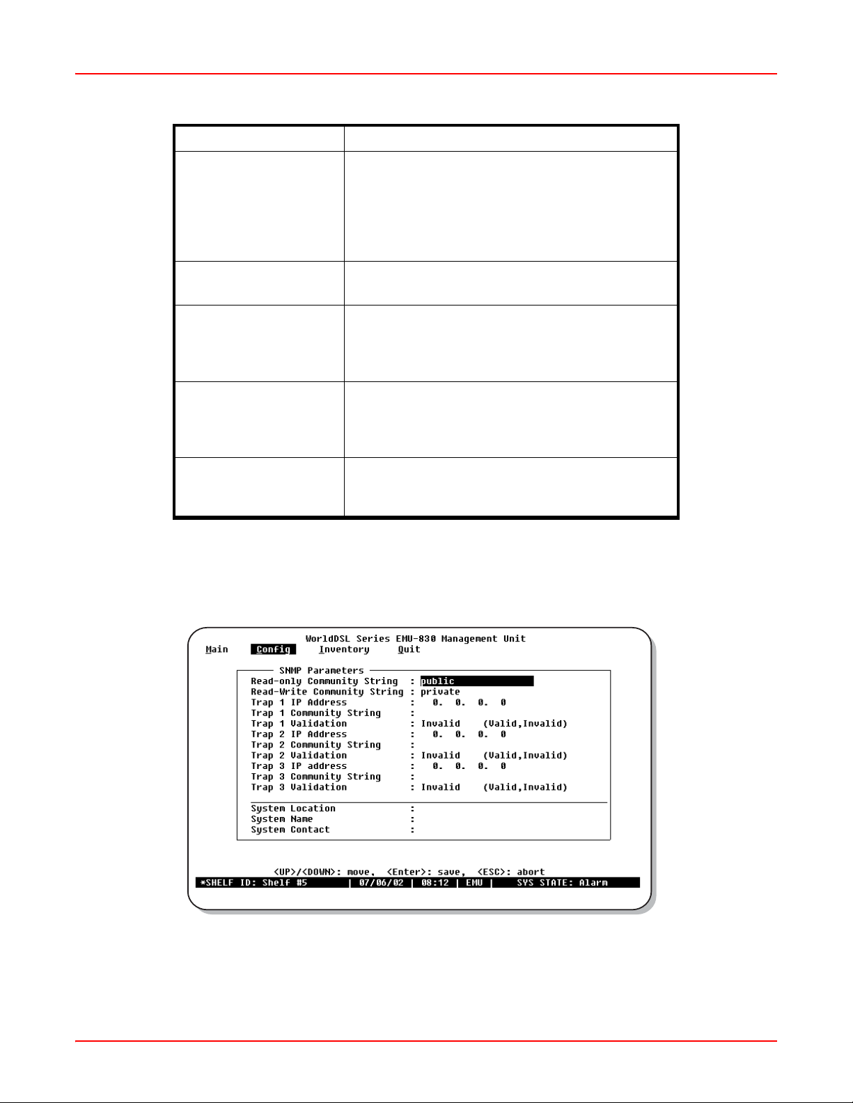
In the Config menu, press N to display the Network Parameters menu (Figure 3-5 on page 3-9). This menu is used
to identify and change the EMU network parameters. The Network Parameters menu options are listed in Table 3-5
on page 3-10.
Æ arrow key to select Config; then press C to display the items in the Config
Figure 3-4. Config Menu
3-8 LTPE-UM-3159-02
Page 41

September 25, 2006 Chapter 3: Provisioning
Figure 3-5. Network Parameters Menu
Note: The network parameters for each EMU must be configured individually. Once configured, each shelf
reports its status and alarms to the local shel f (the shelf with its EMU connected to the VT100 or PC, either
directly or by modem).
The Ethernet Address parameter is read-only and cannot be cha nged by the user. When changes a re made
to the network parameters, the EMU console will promp t to reset to apply the changes.
Consult your network administrator to obtain the required IP addresse s.
Configure Network Parameters for Multishelf TAO and SNMP
To configure the EMU-830 for Multishelf TAO and
basic SNMP operation (if used) over Ethernet LAN:
Step Action
1 In the Network Parameters menu (Figure 3-5 on page 3-9), the Ethernet Connection type is 10BASE-T.
2 Enter values for the Local IP Address, Local IP Subnet Mask, and, if the management station and EMU
are on different subnets, the Default Gateway IP Address (see Table 3-5 on page 3-10). Ensure that you
use values to place all shelves in the multishelf TAO on the same subnet.
3 In the SNMP Parameters menu (Figure 3-6 on page 3-11), configure at least one trap receiver (ignore this
step if you are not using SNMP). Enter the appropriate values for the Trap (management station) IP
Address and Trap Community string, then toggle the Trap Validation field to Valid (see Table 3-6 on page
3-12).
4 Press ENTER to confirm all network settings.
5 Follow the EMU console prompt to reset the EMU.
LTPE-UM-3159-02 3-9
Page 42

Chapter 3: Provisioning September 25, 2006
Configure SNMP Operation Over SLIP
To configure the EMU-830 for basic SNMP operation over SLIP:
Step Action
1 In the Network Parameters menu (Figure 3-5 on page 3-9), enter the Local SLIP IP Address (see Table
3-5 on page 3-10).
2 Enter the Local SLIP Subnet Mask.
3Use the SPACEBAR to select the SLIP Port Baud Rate.
4 Press ENTER to confirm all network settings.
5 Follow the EMU console prompt to reset the EMU.
Configure EMU Autoconfiguration through BOOTP
To use BOOTP capability of the EMU-830 (see Table 3-5):
Step Action
1 In the Network Parameters menu, enter the BOOTP Server IP Address.
2 Enter the BOOTP Gateway IP Address.
3 Toggle the Boot Mode from NVRAM to Network.
4 Press ENTER to confirm all network settings.
5 Follow the EMU console prompt to reset the EMU.
T able 3-5. Network Parame ters
Option Function
Ethernet Address Reflects the hardware Ethernet (MAC) address for
the EMU-830. This field cannot be changed.
Ethernet Connection The Ethernet connection type is 10BASE-T. This
field cannot be changed.
Local IP Address Must be configured for the EMU-830 Ethernet port to
respond to the local management station.
192.168.0.1 is the default setting using Telnet or
SNMP.
Local IP Subnet Mask Allows the EMU-830 to determine if a host (TFTP
server, SNMP management station, or trap receiver)
is on the same local subnet. If it is, the EMU-830 can
communicate directly with the host; if it is not,
messages must be sent through a default router.
255.255.255.0 is the default setting
Default Gateway IP
Address
Local SLIP IP Address Must be configured for the EMU-830 SLIP port to
Enter the IP address of the default gateway the
EMU-830 will use if the EMU-830 and the host are
not on the same network. 0.0.0.0 is the default
setting.
respond to the local management station. 0.0.0.0 is
the default setting, which means SLIP port is not
used.
3-10 L TPE-UM-3159-02
Page 43
September 25, 2006 Chapter 3: Provisioning
Option Function
Local SLIP Subnet Mask Allows the EMU-830 to determine if a host (TFTP
server, SNMP management station, or trap receiver)
is on the same local subnet. If it is, the EMU-830 can
communicate directly with the host; if it is not,
messages must be sent through a default router.
0.0.0.0 is the default setting.
SLIP Port Baud Rate Select the SLIP Port baud rate by toggling to the
desired rate (maximum 19200 bps).
BOOTP Server IP
Address
BOOTP Gateway IP
Address
Boot Mode Select the Boot Mode by toggling between NVRAM
SNMP Parameters Menu
In the Config menu, press S to display the SNMP Parameters menu (Figure 3-6). This menu is used to configure the
EMU-830 for operation with SNMP (ignore this section if you are not using SNMP). The SNMP Parameters menu
options are listed in Table 3-6 on page 3-12.
Enter the IP address for the BOOTP server to which
the EMU-830 is connected. 0.0.0.0 is the default
setting. This information is only required if using the
BOOTP protocol.
Enter the IP address for the gateway for the BOOTP
server. 0.0.0.0 is the default setting. This information
is only required if using the BOOTP protocol and the
BOOTP server is connected through a gateway.
(the default) or NETWORK. BootP/TFTP Server can
be used for uploading software using the Network.
Figure 3-6. SNMP Parameters Menu
LTPE-UM-3159-02 3-11
Page 44

Chapter 3: Provisioning September 25, 2006
Configure SNMP Community Strings
The community string parameters are required to read and write SNMP objects.
In the SNMP Parameters menu (Figure 3-6 on page 3-11), configure the Read-only and Read-Write Community
String par ameters in accordance with Table 3-6.
Configure SNMP Trap Receivers
The SNMP Parameters menu allows you to configure up to three SNMP trap receivers (management stations) to
which all EMU-830 trap messages will be sent.
To configure an SNMP trap receiver:
Step Action
1 In the SNMP Parameters menu (Figure 3-6 on page 3-11), enter the Trap 1 IP Address (see Table 3-6).
2 Enter the Trap 1 Community String.
3 Toggle the Trap 1 Validation field to Valid.
4 Repeat steps 1 through 3 for each trap receiver to be configured.
Configure System Identification
Three options are provided at the bottom of the SNMP Parameters menu to identify each system and the system
contact. These options are System Location, System Name, and System Contact (see Table 3-6).
The System Location is the physical location of the system (such as, Building 1, Corporate Of fice, Main Street, etc.).
System Name is the name you assign to the system (such as, Net 3, CircuitMon, Shelfwatch, etc.). System Contact
is the name, title and/or phone number of the person to contact at the system location.
To configure system identification:
Step Action
1 In the SNMP Parameters menu (Figure 3-6 on page 3-11), enter the System Location (32 characters
maximum).
2 In the System Name field, enter a name for the system (32 characters maximum).
3 In the System Contact field, enter the name, title, and/or phone number of the person to contact at the
system location (32 characters maximum).
4 Press ENTER to confirm settings and return to the top of the Config menu.
Table 3-6. SNMP Parameters Menu
Option Function
Read-only Community
String
Read-write Community
String
Trap 1 IP Address Enter the IP address to which the trap is sent. 0.0.0.0
Enter a community string. SNMP uses the
community string for set and get requests. To read
an SNMP object, the community string settings on
both ends of the system must match.
Enter a community string. SNMP uses the
community string for set and get requests. To write
an SNMP object, the community string settings on
both ends of the system must match.
is the default setting.
3-12 L TPE-UM-3159-02
Page 45

September 25, 2006 Chapter 3: Provisioning
Option Function
Trap 1 Community String Enter a community string. It must match the SNMP
Comm Name string for traps. SNMP uses the
community string for set and get requests.
Trap 1 Validation Select the trap status by toggling between Valid (the
default) or Invalid. Valid enables the trap, invalid
disables it.
Trap 2 IP Address Enter the IP address to which the trap is sent. 0.0.0.0
is the default setting.
Trap 2 Community String Enter a community string. It must match the SNMP
Comm Name string for traps. SNMP uses the
community string for set and get requests.
Trap 2 Validation Select the trap status by toggling between Valid (the
default) or Invalid. Valid enables the trap, invalid
disables it.
Trap 3 IP Address Enter the IP address to which the trap is sent. 0.0.0.0
is the default setting.
Trap 3 Community String Enter a community string. It must match the SNMP
Comm Name string for traps. SNMP uses the
community string for set and get requests.
Trap 3 Validation Select the trap status by toggling between Valid (the
default) or Invalid. Valid enables the trap, invalid
disables it.
System Location Field where you enter the physical location of the
system.
System Name Field where you assign a name to the system.
System Contact Field where you list the name, title, or phone number
of the system operator or administrator.
LTPE-UM-3159-02 3-13
Page 46
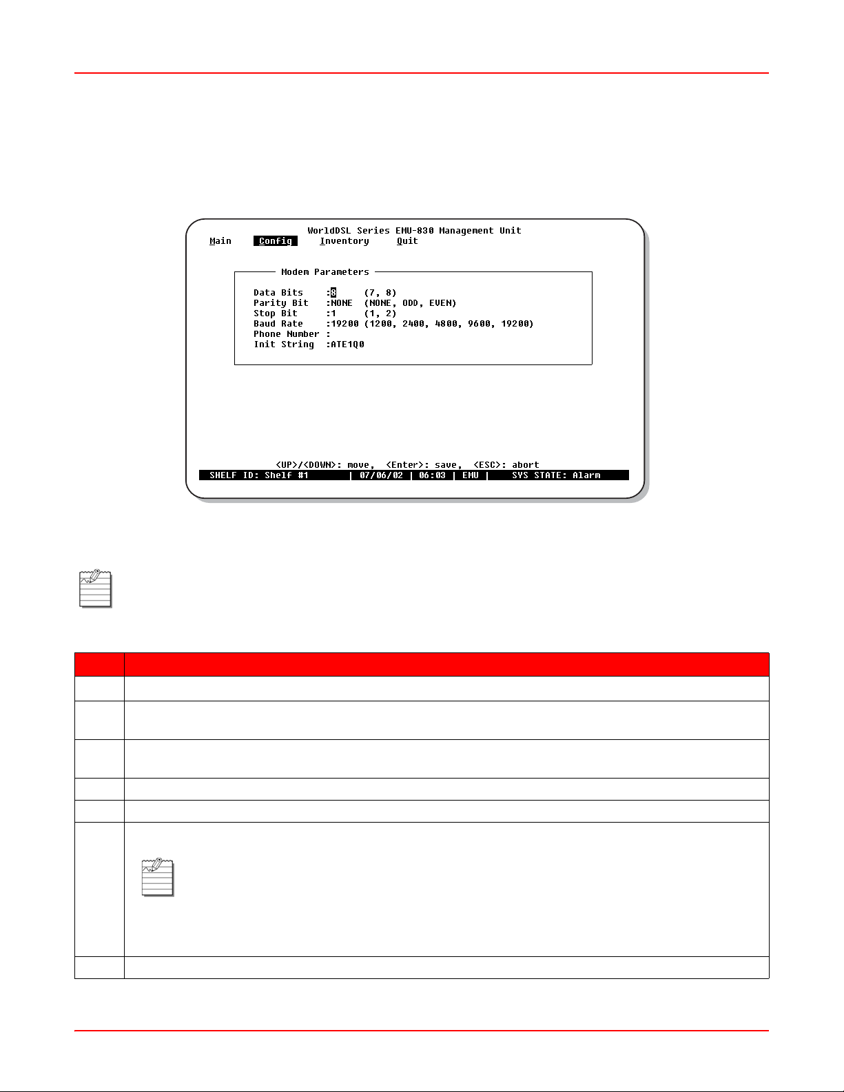
Chapter 3: Provisioning September 25, 2006
Modem Parameters (Configure and Test Dial-out Alarm Reporting)
In the Config menu, press M to display the Modem Parameters menu (Figure 3-7). This menu is used to configure
the EMUs modem parameters for autonomous dial-out reporting of alarms to a remote management statio n or
printer.
Figure 3-7. Modem Parameters Menu
Note: Connect and configure the shelf modem as instructed in “Remote Terminal and Local Shelf Modem
Connections” on page 2-7.
Step Action
1
Navigate the menu using the
2Use the SPACEBAR to toggle the Data Bits field to "7" or "8" (to match modem at remote management
station).
3 Toggle the Parity Bit field to "NONE," "ODD," or "EVEN" (to match modem at remote management
station).
4 Toggle the Stop Bit field to "1" or "2" (to match modem at remote management station).
5 Toggle the Baud Rate field to the appropriate setting (to match modem at remote management station).
6 In the Phone Number field, enter the phone number of the modem at the remote management station.
Note: The Phone Number field must be preceded by "atdt" for tone dialing or "atdp" for pulse
dialing.
The Init String field displays "ATE1Q0." This is the default Hayes compatible modem
initialization string. If you need to change this initialization string, consult your modem user
manual or call the ADC Technical Assistance Center at the number listed on page B-1.
Ç and È arrow keys on the keyboard.
7 Press ENTER to confirm settings and return to the top of the Config menu.
3-14 L TPE-UM-3159-02
Page 47

September 25, 2006 Chapter 3: Provisioning
Step Action
8 Test the EMU’s dial-out alarm reporting as follows:
a. Configure the shelf alarms as instructed on page 3-16.
b. If necessary, select the Remote Alarm Reporting menu item and press ENTER to change the set-
ting from disable (Dis) to enable (Ena). See Figure 3-8.
IMPORTANT
!
c. Disconnect and re-connect an DSL Tip or Ring lead from a shelf. The shelf modem dials the man-
d. Disconnect and re-connect a G.703 interface cable from a shelf. The shelf modem dials the man-
The following steps require that you momentarily disconnect an DSL Tip or Ring lead
and then a G.703 interface cable to test remote alarm reporting. Take steps to ensure
that a customer’s service is not interrupted.
Note: The following alarm reporting screens are examples and do not represent the alarms
displayed in all tests.
agement station, which displays the following alarms on its monitor:
The alarm reporting screen in Figure 3-8 shows that a loss of sync word occurred on both loops
(LOSW*) followed by a loss of sync word on Loop 1 only (LOSW1) and Loop 2 returning to normal
operation (that is, nothing displayed for Loop 2).
agement station, which displays the following alarms on its monitor:
The alarm reporting screen in Figure 3-9 on page 3-16 shows that a loss of signal (LOS*), power
feed open (PFO*), and loss of sync word (LOSW*) occurred on both loops.
Figure 3-8. LOSW* and LOSW1 Alarm Reporting Screen
LTPE-UM-3159-02 3-15
Page 48

Chapter 3: Provisioning September 25, 2006
Figure 3-9. LOS*, PFO* and LOSW* Alarm Reporting Screen
Shelf Alarms Menu
In the Config menu, press H to display the Shelf Alarms menu (Figure 3-10). This menu allows you to enable,
disable, and set the severity of the loss of shelf power, HDSL/G.SHDSL lines down , and loss of external clock alarm .
The Config menu also allows you to configure how each of the alarm re lays respond to an ACO (Alarm Cut- Off). The
ACO can be activated from the EMU-830 front panel pushbut ton or by connecting to ground the EXT (external) ACO
pin on the EMS-83x shelf's alarm connector . Selecting Enable (ENA) causes the associated alarm relay to be retired
(common contact connected to normally closed contact) when an ACO is received.
Figure 3-10. Shelf Alarms Menu
Note: To select the Shelf Alarms menu for a different shelf, press ESC a nd then Q to return to the Network
screen, select a shelf with the
shelf. Press C and then H to display the Shelf Alarms menu for the selected shelf.
3-16 L TPE-UM-3159-02
Ç and È arrow keys, and press L to open the Main menu screen for that
Page 49

September 25, 2006 Chapter 3: Provisioning
To configure the shelf alarms:
Step Action
1
Navigate the menu using the
2 In the Loss of power on one 48V supply field, use the SPACEBAR to select DIS (disabled), MIN
(minimum), MAJ (major), or CRT (critical).
3 In the HDSL alarm if 3 lines down field, use the SPACEBAR to select DIS (disabled), MIN (minimum),
MAJ (major), or CRT (critical).
4 In the Loss of External Clock field (on EMU-830 List 6A only), use the SPACEBAR to select DIS
(disabled), MIN (minimum), MAJ (major), or CRT (critical).
5 In the ACO Retirement of Alarm Relays field, use the SPACEBAR to select DIS (disabled) or ENA
(enabled) for the Audible and Visual fields of the Critical, Major, and Minor alarm relays.
6 Press ENTER to confirm settings and return to the top of the Config menu.
Remote Alarm Reporting
This Config menu option (Figure 3-11) must be enabled when your system is configured for autonomous dial-out
reporting of alarms to a remote management station or printer. If necessary, select the Remote Alarm Reporting
menu item and press ENTER to change the setting from disabled (Dis) to enabled (Ena).
Ç and È arrow keys on the keyboard.
Figure 3-11. Remote Alarm Reporting Menu Item
Set Date and Time
Use the
3-18). This dialog box allows you to enter the current Date and Time so the di splayed alarm repor ting information is
correct.
The Date format is DD/MM/YYYY (day/month/year). The Time format is HH:MM:SS (hour:minute:second) and
displays as a 24-hour clock (01:00:00 through 24:59:59).
LTPE-UM-3159-02 3-17
Æ arrow key to select Config, then press D to display the Set Date/Time dialog box (Figure 3-12 on page
Note: Setting the EMU’s date and time automatically sets the date and time for all HDSL/G.SHDSL cards
in the shelf.
Page 50

Chapter 3: Provisioning September 25, 2006
To set the date and time:
Step Action
1
Use the
and time in the respective fields.
2 Press ENTER to confirm settings and return to the top of the Config menu.
Ç and È arrow keys to select the DD/MM/YYYY and HH:MM:SS fields. Enter the current date
Figure 3-12. Set Date/Time Dialog Box
Change Password
In the Config menu, press P to display the Change Password dialog box (Figure 3-13 on page 3-19). This dialog box
is used to select or change your password. You can use the letters A through Z (case sensitive), numbers 0 through
9, spaces, and any keyboard symbol.
To select or change your password:
Step Action
1 Do one of the following:
a. If you do not have a password, press ENTER.
b. Type your old password and press ENTER.
2 When the second password screen is displayed, type the new password (20 char acters maximum), then
press ENTER.
3 When the next password screen appears, re-enter the new password (exa ctly as originally entered), then
press ENTER.
3-18 L TPE-UM-3159-02
Page 51

September 25, 2006 Chapter 3: Provisioning
Figure 3-13. Change Password Dialog Box
Set Shelf ID
In the Config menu, press I to display the Set Shelf ID dialog box (Figure 3-14 on page 3- 19). This dialog box allows
you to enter the shelf ID for each management unit. You can use the letters A through Z (case sensitive), numbers 0
through 9, spaces, and any symbol.
Figure 3-14. Set Shelf ID Dialog Box
LTPE-UM-3159-02 3-19
Page 52

Chapter 3: Provisioning September 25, 2006
To set the shelf ID:
Step Action
1 In the Enter Shelf ID field, type the Shelf ID (32 characters maximum) and press ENTER.
2 Press any key to return to the top of the Config menu.
3 Reset the EMU as instructed on page 3-22.
Terminal Settings
In the Config menu, press T to display the Terminal Settings menu (Figure 3-15). This menu is used to specify a
terminal setting that displays the best horizontal and vertical lines on your monitor .
Figure 3-15. Terminal Settings Menu
3-20 L TPE-UM-3159-02
Page 53

September 25, 2006 Chapter 3: Provisioning
To specify a terminal setting, do one of the following:
Step Action
1 If you are not using a Windows terminal, select a menu item with the best horizontal line, then press
ENTER. For example, "_ _ _ _ _" versus "________", where "________" is the best.
2 If you are using a Windows terminal, select the Windows Terminal menu item, then press ENTER.
Set to Factory Defaults
In the Config menu, press F to display the "restore to factory defaults" warning prompt (Figure3-16).
Figure 3-16. Restore To Factory Defaults Warning Prompt
IMPORTANT
!
Do one of the following:
• Press Y (yes) to reset the EMU to factory default settings (then log on to the EMU console menu if you wish to
make configuration changes).
• Press N (no) to retain your special configuration settings.
Pressing Y in this screen resets the EMU-830 to factory default settings, which erases any special
configuration settings you have specified.
Note: Resetting the EMU to factory defaults will reset the EMU and log you off from the EMU console menu
and requires that you log on again on to regain access. All alarm reporting information is lost.
LTPE-UM-3159-02 3-21
Page 54

Chapter 3: Provisioning September 25, 2006
Reset EMU
In the Config menu, press R to display the "reset EMU" warning prompt (Figure 3-17).
Figure 3-17. Reset EMU Warning Prompt
IMPORTANT
!
Do one of the following:
• Press Y (yes) to reset the EMU (then log on to the EMU console menu if you wish to make configuration
changes).
• Press N (no) to return to the Config menu.
Inventory Information Screen
Use the
3-18 on page 3-23). This is read-only screen providing information about the EMU-830. The data included in the
Inventory Information screen is listed in Table 3-7 on page 3-23.
If you reset the EMU-830, all alarm reporting information is lost.
Note: Resetting the EMU will log you off from the EMU console menu and requires that you log on again
on to regain access.
Æ arrow key to select Inventory , then press ENTER to display the Inventory In formation screen (see Figure
3-22 L TPE-UM-3159-02
Page 55

September 25, 2006 Chapter 3: Provisioning
Figure 3-18. Inventory Information Screen
Table 3-7. Data in Inventory Information Screen
Field Description
Product Type Displays the EMU model number.
List Number Displays the EMU list number, which identifies the version of the unit.
Hardware Revision Displays the EMU hardware revision number
Serial Number Displays the unique serial number of the EMU for inventory and service tracking.
Manufacture Date Displays the date the EMU was manufactured.
Software Part Number Displays the ADC part number of the firmware.
Checksum Displays the checksum of the EMU proms.
Software Revision Displays the currently installed firmware version level of the EMU.
Software Date Displays the date that the firmware was released.
LTPE-UM-3159-02 3-23
Page 56

Chapter 3: Provisioning September 25, 2006
MANAGING FIRMWARE THROUGH THE UPLOAD MENU
The Upload menu provides the mechanism to upload image files to local or remote line units or EMUs.
Upload to a Local or Remote Line Unit
To upad to a local or remote line unit:
Step Action
1 If viewing the Main menu screen (Figure 3-3 on page 3-5), press ESC and type Q to return to the Network
screen (Figure 3-2 on page 3-4).
2
In the Network screen, use the
Note: The shelf with the ">" symbol (for example, >Shelf #28) is the local shelf connected to the
management station PC. Other shelves (without the > symbol) are remote shelves connected to
the local shelf through Ethernet.
3 Type the letter U. The Upload menu is displayed (Figure 3-19 on page 3-25).
4 From the Upload menu, select Upload Line Unit. The Upload to Line Unit dialog box is displayed (Figure
3-20 on page 3-25).
5 In the Enter Line Unit: field, type the slot number of the line unit to be uploaded.
6
Use the
unit type. The available line unit types are listed in Table 3-8 on page 3-25.
7 When you are ready to upload to the line unit, press ENTER. The Xmodem transfer message is displayed
(Figure 3-21 on page 3-26).
8 Go to the new firmware file (for example, sys.img).
9 From the Terminal utility Settings menu, select Binary Transfers, then select XMODEM.
10 From the Terminal utility Transfers menu, select Send Binary File (do not select Send Text File).
11 Enter the file path and name, then click OK to begin the upload to the local or remote line unit:
Ç and È arrow keys to select the Line Unit Type field, press the SPACEBAR to select the line
Ç and È arrow keys to select the local shelf or a remote shelf.
If uploading to a line unit on a remote shelf, the TAO Multishelf message is displayed, followed by the
Remote line unit uploading message.
If uploading to a line unit on a local shelf, the Local line unit uploading message is displayed (Figure 3-22
on page 3-26).
Do not abort the download procedure when an XModem transfer is in progress.
3-24 L TPE-UM-3159-02
Page 57

September 25, 2006 Chapter 3: Provisioning
Figure 3-19. Upload Line Unit Menu Item
Figure 3-20. Upload to Line Unit Dialog Box
T able 3-8. Line Unit Uploads
Line Unit Type Local Unit Target Unit
Local LTU/STU-C or
NTU/STU-R
LTU/STU-C LTU/STU-C Local LTU/STU-C
LTU/STU-C NTU/STU-R Remote LTU/STU-C
NTU/STU-R LTU/STU-C Remote NTU/STU-R
NTU/STU-R NTU/STU-R Local NTU/STU-R
REG1/Loop 1 LTU/STU-C or
NTU/STU-R
REG2/Loop 1 LTU/STU-C or
NTU/STU-R
LTPE-UM-3159-02 3-25
Local LTU/STU-C or
NTU/STU-R
Regenerator #1
Regenerator #2
Page 58

Chapter 3: Provisioning September 25, 2006
Figure 3-21. Xmodem Tr ans fer Message
Figure 3-22. Local Line Unit Uploading Message
3-26 L TPE-UM-3159-02
Page 59

September 25, 2006 Chapter 3: Provisioning
Upload Local EMU
To upload to the local EMU:
Note: If using the Xmodem protocol to upload the local EMU directly from your management station, copy
the firmware file to your management station hard disk before proceeding. This greatly reduces the time
required for the upload process.
Step Action
1 In the Network screen (Figure 3-2 on page 3-4), select the local shelf. That is, the shelf with the ">"
symbol. For example, >Shelf # 28.
2 Type the letter U. The Upload menu is displayed (Figure 3-23 on page 3-28).
3 From the Upload menu, select Upl o ad EMU. The Upload to Local EMU dialog box is displayed
(Figure 3-24 on page 3-28).
4Press the SPACEBAR to select Xmodem or TFTP file transfers. (Select TFTP if uploading the local EMU
from a TFTP server through Ethernet LAN; select Xmodem if uploading the local EMU from your
management station through a cable connected to the local EMU console port.)
5 Do one of the following:
a. If using TFTP Server:
1. Enter the server's IP address and the upload file name (for example, sys.img).
2. Press ENTER. The TFTP Upload EMU prompt is displayed (Figure 3-25 on page 3-29).
3. Press Y to upload the local EMU.
b. If using Xmodem:
IMPORTANT
!
1. Press ENTER. The Xmodem Upload EMU prompt is displayed (Figure 3-26 on page 3-29).
2. Press Y. The Boot Loader prompt is displayed (Figure 3-27 on page 3-30).
3. If uploading from CD-ROM, insert the CD-ROM into your management station's
CD-ROM drive.
4. From the Terminal utility Settings menu, select Binary Transfers, then select XMODEM.
5. From the Terminal utilities Transfers menu, select Send Binary File (do not select Send
Text File).
6. Enter the file path and name, then click OK to begin the upload.
Be sure that the firmware file has been copied to hard disk or that the CD-ROM
with the file is available and ready for use. Xmodem erases the EMU flash
memory upon execution of step 2 below and thereafter must receive the image
file upload to resume normal EMU operation.
LTPE-UM-3159-02 3-27
Page 60
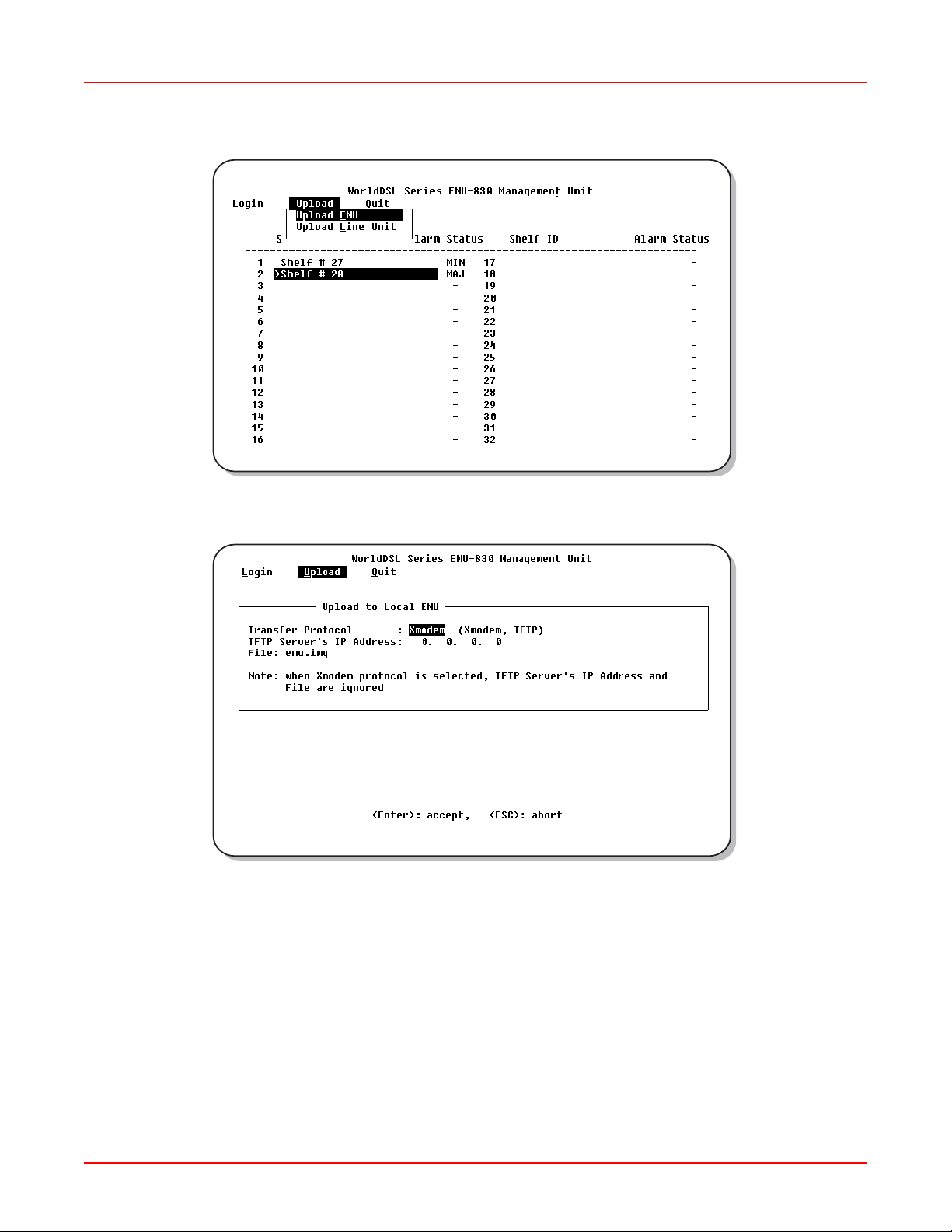
Chapter 3: Provisioning September 25, 2006
Figure 3-23. Upload EMU Menu Item
Figure 3-24. Upload to Local EMU Dialog Box
3-28 L TPE-UM-3159-02
Page 61

September 25, 2006 Chapter 3: Provisioning
Figure 3-25. TFTP Upload EMU Prompt
Figure 3-26. Xmodem Upload EMU Prompt
LTPE-UM-3159-02 3-29
Page 62

Chapter 3: Provisioning September 25, 2006
Figure 3-27. Boot Loader Prompt
Upload Remote EMU
After uploading the local EMU, its firmware image can be up loaded to the remote EMUs (the use of files is not
required). To upload to a remote EMU:
Step Action
1 In the Network screen (Figure 3-2 on page 3-4), select a remote shelf. That is, a shelf without the ">"
symbol. For example, Shelf # 27.
2 Type the letter U. The Upload menu is displayed (Figure 3-19 on page 3-25).
3 From the Upload menu, select Upl o ad EMU. The Remote Upload EMU dialog is displayed (Figure 3-28).
4 Press Y to upload the remote EMU. The Remote EMU Upload message is displayed (Figure 3-29 on
page 3-31).
5 Press any key to return to the Network screen (Figure 3-2 on page 3-4).
Figure 3-28. Remote Upload EMU Dialog
3-30 L TPE-UM-3159-02
Page 63

September 25, 2006 Chapter 3: Provisioning
Figure 3-29. Remote EMU Upload Message
LTPE-UM-3159-02 3-31
Page 64

Chapter 3: Provisioning September 25, 2006
3-32 L TPE-UM-3159-02
Page 65

Appendix
SPECIFICATIONS
ALARMS
Relays 6 form C relays: critical visual, critical audible, major visual, major
audible, minor visual, minor audible.
Maximum switching power 30 W
Maximum switching current 1 A
Surge voltage withstand 1500 V
Shelf alarms Power input failure, programmable number of HDSL loops in the shelf
are down, loss of external clock (EMU-830 List 6A only)
LEDs Critical, Major, Minor alarm
POWER REQUIREMENTS
Consumption 7.5 W
A
ENVIRONMENTAL
Operating Temperature 0 °C to +50 °C
Humidity Up to 95% non condensing
REGULATORY APPROVALS
Safety EN 60950
EMC/EMI EN300 386-2
COMPATIBILITY
The EMU-830 is compatible with HDSL, G.SHDLS cards, desktop units, doublers (regenerators), and exchange
office management shelves in the WorldDSL product line. Universal Termination Units (UTUs) can be configured as
LTUs or NTUs. WD92xGx can be configured as STU-Cs or STU-Rs. Typically the LTU/STU-C DSL cards are
installed in the management shelf and the NTU/STU-R DSL cards are deployed at the remote site. You can,
however, use either an LTU/STU-C or NTU/STU-R DSL card in a shelf as the EMU-830 allows terminal access to
both types of DSL cards when installed in a shelf. Alarm management, however, is only performed on LTU/STU-C
cards and their attached circuit elements.
The following is an abbreviated list of EMU-compatible WorldDSL products.
• Shelves: All EMS-83x List 2
• HDSL Cards: All LTU-80x List x, UTU-80x Lx
• Universal Termination Units: All UTU-9xx
• Integrated Desktop Units: All ETU-8xx and ETU-9xx
• Doublers (regenerators): All EDU-840 List x
• G.SHDSL Cards: WD92xGx line cards
LTPE-UM-3159-02 A-1
Page 66

Appendix A: Specifications September 25, 2006
A-2 LTPE-UM-3159-02
Page 67

Appendix
B
PRODUCT SUPPORT
ADC Customer Service Group provides expert pre-sales support and training for all of its products. Technical
support is available 24 hours a day, 7 days a week by contacting the ADC Technical Assistance Center.
Sales Assistance: 800.366.3891 Quotation Proposals, Ordering and Delivery General,
and Product Information
Systems Integration: 800.366.3891 Complete Solutions (from concept to installation),
Network Design and Integration Testing, System TurnUp and Testing, Network Monitoring (upstream or
downstream), Power Monitoring and Remote
Surveillance, Service/Maintenance Agreements, and
Systems Operation
ADC Technical Assistance Center:
800.366.3891
Email: wsd.support@adc.com
Online Technical Support: www.adc.com/Knowledge_Base/index.jsp
Online Technical Publications: www.adc.com/documentationlibrary/
Product Return Department: 800.366.3891
Email: repair.return@adc.com
Technical Information, System/Network Configuration,
Product Specification and Application, Training
(product-specific), Installation and Operation
Assistance, and Troubleshooting and Repair/Field
Assistance
technicalpublications/
ADC Return Material Authorization (RMA) number and
instructions must be obtained before returning products.
LTPE-UM-3159-02 B-1
Page 68

Appendix B: Product Support September 25, 2006
B-2 LTPE-UM-3159-02
Page 69

GLOSSARY
A
AIS – Alarm Indication Signal
ALM – Alarm
ANSI – American National Standards Institute
AWG – American Wire Gage
B
BER – Bit Error Rate
C
C – Centigrade
COM – Communication
CRC – Cyclic Redundancy Check
CTS – Clear To Send
D
D15F – D-type 15-pin Female Connector
D25F – D-type 25-pin Female Connector
D9F – D-type 9-pin Female Connector
dB – Decibel
DCE – Data Communications Equipment
Det – Detector
dnl – Download
DS0 – Digital Service, Level 0 (64 kbps)
DSR – Data Set Ready
DTE – Data Terminal Equipment
DTR – Data Terminal Ready
E
EMC – Electromagnetic Compliance
EMI – Electromagnetic Interference
EMS – Exchange Office Management Shelf
EMU – Exchange Office Management Unit
ES – Errored Second
ETR – ETSI Technical Report
ETSI – European Telecommunications Standards Institute
ETU – ETSI Termination Unit
EXT – External G.SHDSL Clock
H
H/W – Hardware
HDSL – High-bit-rate Digital Subscriber Line
Hz – Hertz
I/F – Interface
ID – Identification
INT – Internal
LTPE-UM-3159-02 GL-1
Page 70

Glossary September 25, 2006
K
kbps – kilobytes per second
km – kilometers
L
LED – Light Emitting Diode
LL – Local Loopback
LDC – Loss of Data Port (Nx64k) Clock
LEC – Loss of External Clock
LOC – Loss of Clock
LOSW – Loss of Sync Word
LPBK – Loopback
LTU – Line Termination Unit
M
M34F – M-type 34-pin Female Connector
MAR – Margin
Mbps – Megabits per second
MHz – Megahertz
mm – millimeter
N
NC – Normally Closed
NO – Normally Open
NTU – Network Termination Unit
NVRAM – Non-volatile Random Access Memory
Nx64k – Number (N) of 64 kbps DS0 time slots mapped to a data port.
O
Op – Operation
PFO – Power Feed Open
PFS – Power Feed Short
ppm – pulse per minute
PRBS – Pseudorandom Bit Sequence
R
RAM – Random Access Memory
REM – Remote
RL – Remote Loopback
RLSD – Received Line Signal Detector
RTS – Ready to Send
S
SD – Transmit Data
SLIP – Serial Line Internet Protocol
ST – Send Timing
STU-C – SHDSL Terminating Unit for the CO
STU-R – SHDSL Terminating Unit for the RT
S/W – Software
GL-2 LTPE-UM-3159-02
Page 71

September 25, 2006 Glossary
T
TM – Test Mo de
TT – Termi na l Timing
U
UAS – Unavailable Seconds
UTU – Universal Termination Unit
V
V – Volts
Vdc – Volts direct current
VT100 – A terminal-emulation system
W
W – Watts
LTPE-UM-3159-02 GL-3
Page 72

Glossary September 25, 2006
GL-4 LTPE-UM-3159-02
Page 73

Certification and Warranty
FCC Class A Compliance
This equipment has been tested and found to comply with the limit s for a Class A digit al device, pursuant to Part 15
of the FCC Rules. These limits are designed to provide reasonable protection against harmful interference when
the equipment is operated in a commercial environment. This equipment generates, uses, and can radiate radio
frequency energy and, if not installed and used in accordance with the instruction manual, ma y cause harmful inte rference to radio communications. Operation of this equipment in a residential area is likely to cause harmful interference in which case the user will be required to correct the interference at his own expense.
Limited Warranty
Product warranty is determined by your service agreement. Refer to the ADC Warranty/Software Handbook for
additional information, or contact your sales representative or Customer Service for details.
Modifications
The FCC requires the user to be notified that any changes or modifications made to this device that are not
expressly approved by ADC voids the user’s warranty.
All wiring external to the products should follo w the provisio ns of the curren t editio n of the National Electrica l Code.
Safety Standards Compliance
This equipment has been tested and verified to comply with the applicable sections of the following safety standards:
• GR 63-CORE - Network Equipment-Building System (NEBS) Requirements
• GR 1089-CORE - Electromagnetic Compatibility and Electrical Safety
• Binational Standard, UL-60950 3rd Edition/CSA1459 C22.2 No. 60950-00: Safety of Information Technology
Equipment
For technical assistance, refer to “Appendix B: Product Support” on page B-1.
Page 74

World Headquarters
ADC Telec ommunications, Inc.
PO Box 1101
Minneapolis, MN 55440-1101 USA
For Technical Assistance
Tel: 800.366.3891
WorldDSLTM Exchange Office Management Unit
EMU-830 User Manual
Document Number:
´-qb¶2I¨
1381662
L TPE-UM-3159-02
 Loading...