

Page 1
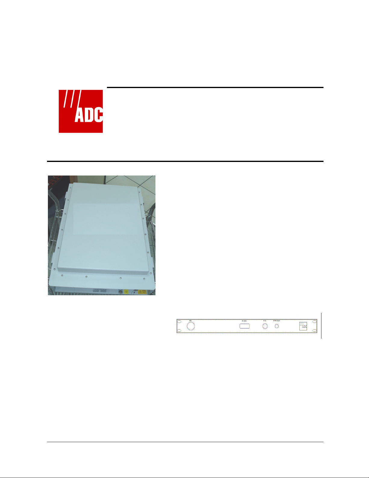
WiMax Optical Fiber Repeater 10W
Installation and Operation Manual
Remote Unit Host Unit
February 2008
Document No. 913011900 Rev. 1.1
Document No. 913011900 Rev. 1.0 Proprietary Document
Page 2

WiMax Optical Fiber Repeater 10W Installation and Operation Manual
Copyright
All data and information contained in or disclosed by this document is confidential and
proprietary information of Unity Wireless Ltd and all rights therein are expressly reserved. By
accepting this material, the recipient agrees that this material and the information contained
therein is held in confidence and in trust and will not be used, copied, reproduced in whole or
in part, nor its Contents revealed in any manner to others, without the explicit written
permission of Unity Wireless Ltd.
Unity Wireless Ltd. Copyright© 2008, Unity Wireless Ltd.
Unity Wireless Ltd. reserves the right to change specifications without notice.
*All third-party trademarks are the properties of their registered owners.
Preface
This manual provides instructions for mounting, setting-up, and monitoring ADC OR
system.
The WiMax 10W Optical Fiber Repeater is used to enhance the performance of
Wimax networks by improving the coverage of the base station and increasing their
traffic.
As a result, the resources of the base station are utilized more efficiently.
In addition, ADC Optical fiber Repeater is a flexible and cost-effective solution that
enables the operator to provide cellular coverage without dependence on the original
cell site coverage area. It is an ideal way to achieve targeted coverage of remote
areas and ‘coverage holes’, and enables advanced coverage schemes, such as BTS
hoteling and distributed coverage for high data-rate networks.
A powerful feature provided enables monitoring and controlling the parameters of
each site from the other site (the Host unit can be controlled from the Remote unit
and vice-versa), using a dedicated channel outside the WiMax frequency band.
This channel is used also to synchronize the TDD frame between the Remote and
Host units.
ADC Repeater may be secured to an interior or exterior wall or attached to a
concrete slab.
Records of Changes
Revision Description Initiated by Date
1.0 Preliminary Release Ram Dishon November 2007
1.1 Update Ram Dishon February 2008
Document No. 913011900 Rev. 1.1 Proprietary Document
ii
Page 3
WiMax Optical Fiber Repeater 10W Installation and Operation Manual
Safety Information
This section describes the use of warnings, cautions, and notes in this manual. It is
the user’s responsibility to follow all safety instructions and regulations.
NOTE: Notes clarify issues.
CAUTION
This symbol indicates special CAUTION required in a
procedure. CAUTION signs prevent actions that may result in
equipment malfunction or damage.
WARNING
WARNING signs prevent actions that may result in harm to
personnel.
Document No. 913011900 Rev. 1.1 Proprietary Document
iii
Page 4
WiMax Optical Fiber Repeater 10W Installation and Operation Manual
FCC Part 15A Compliance Statement
This device complies with Part 15 Class A of the FCC rules. Operation is
subject to the following two conditions: (1) this device may not cause
harmful interference, and (2) this device must accept any interference
received, including interference that may cause undesired operation.
These limits are designed to provide reasonable protection against harmful
interference when the equipment is operated in a commercial environment.
This equipment generates, uses, and can radiate Radio Frequency energy
and, if not installed and used in accordance with the instruction manual,
may cause harmful interference to radio communication. Operation of this
equipment in a residential area is likely to cause harmful interference in
which case the users will be required to correct the interference at their
own expense.
CAUTION
Changes or Modifications not expressly approved by ADC
could void the user’s authority to operate the equipment.
For customer and technical support, contact
ADC Telecommunications, Inc.
P.O. Box 1101, Minneapolis, Minnesota 55440-1101
In U.S.A. and Canada: 1-800-366-3891
Outside U.S.A. and Canada: (952) 928-8080
Fax: (952) 917-1717
or send an e-mail to wireless.tac@adc.com
WARRANTY
ADC Telecommunications, Inc. warrants its products as per agreement.
Exclusions
The warranty (as per the agreement) shall not apply to defects resulting from
improper or inadequate use, unauthorized modifications or misuse.
Document No. 913011900 Rev. 1.1 Proprietary Document
iv
Page 5
WiMax Optical Fiber Repeater 10W Installation and Operation Manual
Warranty Limitations
Under no circumstances will ADC Telecommunications, Inc. be liable in any way to
the user or any third party for damages, including any loss of profits, lost savings, or
other incidental or consequential damages arising out of the use, or inability to use,
the product.
System Measurement and Testing Warnings
WARNING
When installing equipment, always connect the grounding
cable first, only then connect the other cables.
When testing the units in the lab or during field installation,
always practice RF radiation safety rules. It is not
recommended for service or lab personnel to work closer
than two meters from the Remote unit antenna surfaces
when it is operating.
CAUTIONS
• Switch off the AC or DC power to the unit before
connecting or disconnecting any cable.
• Do not connect or disconnect any RF coaxial
connectors while power is applied to the Repeater.
Disconnect power first.
• Do not apply more than +10dBm of RF input power to
any RF port of the OR system, or irreversible damage
may occur.
• When measuring high power outputs, always verify
that the equipment input port is capable of handling
the expected output power.
• During lab or field tests, with power applied to the
Repeater, do not use any mobile transmitters in a
range of less than 10 meters from the unit. An
unexpectedly high RF power might appear at the
output ports, which might in turn damage the
measuring equipment connected to that port.
Document No. 913011900 Rev. 1.1 Proprietary Document
v
Page 6

WiMax Optical Fiber Repeater 10W Installation and Operation Manual
Glossary
ALC Automatic Level Control
BDA Bi-Directional Amplifier
BT Bias T
BTS Base Transceiver Station
dB Decibel measurement of gain and loss
dBm Decibel measurement of power, related to 1mW
dBmO Decibel measurement of optical power, related to 1mWO
Ec Energy per chip received at the mobile's rake receiver
FWD Down-link from the donor base station to the mobile users,
synonym to DL
HPA High Power Amplifier
Io Interference
LNA Low Noise Amplifier
LPU Low Power Unit
M&C Monitoring and Control
MS Mobile Station
mW Milliwatt
NF Noise Figure
NOC Network Operating Center
OR Optical Repeater (Fiber)
PA Power Amplifier
RVS Up-link from the mobile users to the donor base station,
synonym to UL
Rx Receive
TDR Time-Domain Reflectometer
Tx Transmit
Document No. 913011900 Rev. 1.1 Proprietary Document
vi
Page 7

WiMax Optical Fiber Repeater 10W Installation and Operation Manual
Table of Contents
1 Introduction........................................................................................................... 1-1
1.1About ADC Optical Fiber Repeater (OR) ....................................................................................... 1-1
1.2OR System Description................................................................................................................. 1-2
1.2.1General Description .......................................................................................................... 1-2
1.2.2Major Advantages ............................................................................................................ 1-3
2 Installation Procedure............................................................................................ 2-1
2.1Pre-installation Procedures ............................................................................................................ 2-1
2.1.1Receiving and Inspecting the Repeater ............................................................................... 2-1
Required Tools and Test Equipment .......................................................................................... 2-3
2.2Run Sweep Test ........................................................................................................................... 2-3
2.3Host Unit Installation.................................................................................................................... 2-4
2.3.1Mount the Host Unit ......................................................................................................... 2-4
2.3.2Outside the BTS enclosure ................................................................................................ 2-4
2.3.3Inside the BTS enclosure................................................................................................... 2-4
2.3.4Prepare the Electrical Power Connections........................................................................... 2-4
2.4Optical Fiber Test......................................................................................................................... 2-5
2.4.1Power Up the Host Unit. ................................................................................................... 2-5
2.5Mount the Distribution Antennas ................................................................................................... 2-5
2.6Mount the Remote Unit................................................................................................................. 2-6
2.6.1Precautions ...................................................................................................................... 2-6
2.6.2Remote Unit Installation - General Instructions................................................................... 2-6
2.6.3Sealing and Weatherproofing............................................................................................. 2-6
2.6.4Remote Unit Mounting ..................................................................................................... 2-8
2.6.5Cables Connection............................................................................................................ 2-9
3 OR System Setup and Alignment .......................................................................... 3-1
3.1Connect To The Repeater .............................................................................................................. 3-1
3.2Set the System Parameters............................................................................................................. 3-5
3.2.1System Setup Instructions ................................................................................................. 3-6
3.2.2Remote Unit FWD Gain Optimization................................................................................ 3-6
3.2.3Host Unit RVS Gain Optimization ..................................................................................... 3-7
3.2.4Noise Rise Check ............................................................................................................. 3-7
4 Troubleshooting The OR System........................................................................... 4-1
4.1Troubleshooting ........................................................................................................................... 4-1
4.2LEDs........................................................................................................................................... 4-1
4.2.1LEDs Description ............................................................................................................. 4-1
Appendix A. Specifications.................................................................................................... 1
Host Unit Specifications ...............................................................................................................1
Remote Unit Specifications ..........................................................................................................2
Appendix B. Cables Connections and Pinout ......................................................................... 3
Host Unit AC Power Cable Pin-out.........................................................................................................3
Document No. 913011900 Rev. 1.1 Proprietary Document
vii
Page 8

WiMax Optical Fiber Repeater 10W Installation and Operation Manual
Remote Unit AC Power Cable Pin-out ................................................................................................... 4
Common Cables ...................................................................................................................................5
Grounding Cables. ......................................................................................................................5
RS232 Cable:..............................................................................................................................5
Appendix C. Accessories........................................................................................................ 6
Remote Unit Mounting Frame Dimensions....................................................................................6
Appendix D. Records ............................................................................................................. 7
Document No. 913011900 Rev. 1.1 Proprietary Document
viii
Page 9
1 Introduction
1.1 About ADC Optical Fiber Repeater (OR)
ADC optical fiber repeater provides Up-link (RVS) and Down-link (FWD) cell
coverage extension. It serves as a sophisticated remote bi-directional
booster, sensing and re-amplifying the RF transmission in FWD (from the
base-station to the mobile users), and in RVS (from the mobile-users to the
base-station), concurrently. Coverage extension results in increasing traffic
through the base station, thus improving utilization of the Base Transceiver
Station (BTS) resources.
The WiMax system is an interactive, environment-sensitive network.
Optimization of this network involves above all - coverage control. Repeaters
in the WIMAX network are therefore highly interactive with the donor cell and
the neighboring cells, and require flexible tuning and control. Their
effectiveness depends highly on these and additional features.
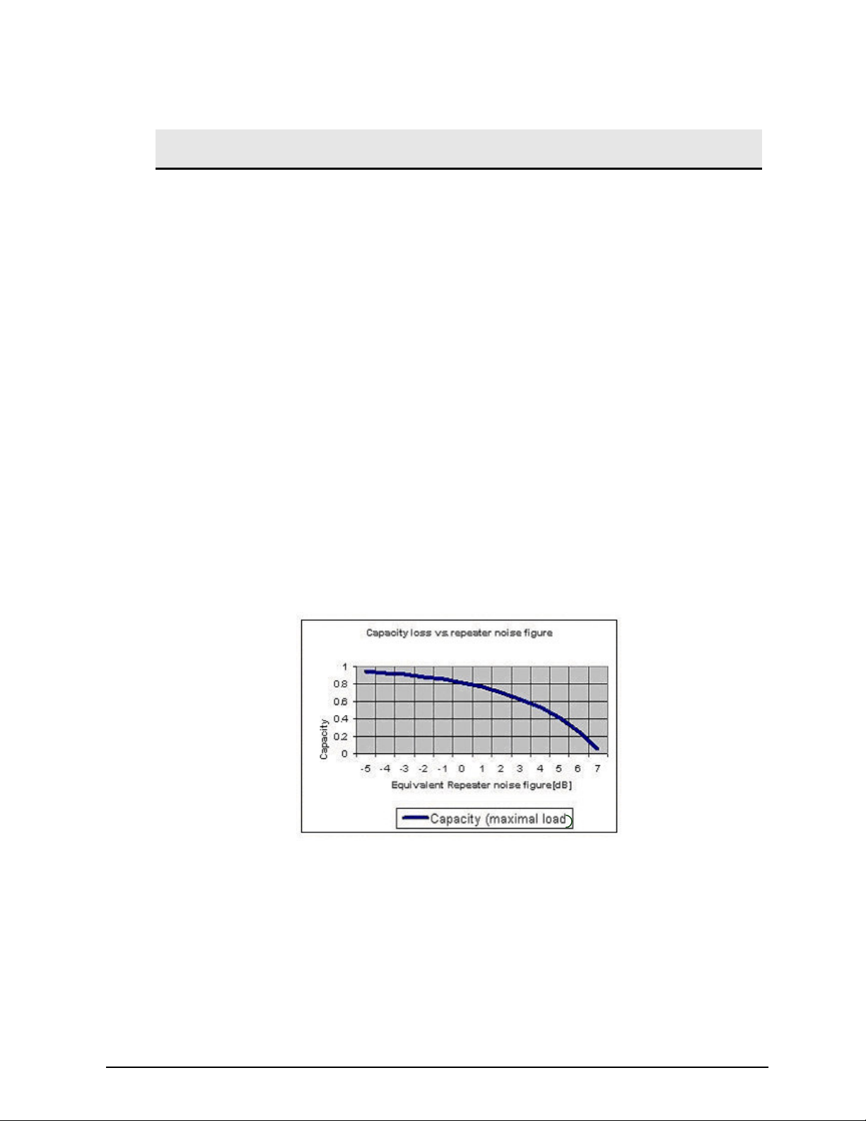
The Repeater Transferred-Noise, as appearing at the input to the shareddonor Base Station receiver, has a detrimental effect on the cell capacity, as
shown in Figure 1-1.
Figure
1-1 Capacity loss vs. repeater noise
A new added feature enables monitoring and control of each site from the
other site, i.e. the Remote unit can be controlled from the Host unit and viceversa.
Copyright 1-1 Proprietary Document
Page 10

WiMax Optical Fiber Repeater 10W Installation and Operation Manual
Overall Unique Advantages
The OR product line shares unique features for exceptional coverage, low
impact on the cell, high controllability, and low maintenance cost. The Remote
unit is built of outdoor grade technology and a weather-proof unit, that
guarantees low Noise Figure (NF), high power efficiency, unique flexibility in
installation, and high reliability.
1.2 OR System Description
1.2.1 General Description
The ADC OR system consists of two units, a Host unit, installed close to the
BTS, and a Remote unit, installed in the remote site. This integrated structure
provides the advantage of easy installation and maintenance.
The Host Unit contains the following main units:
• Optical transceiver
• Signal processing and controller
• Power supply
Optical transceiver
The optical transceiver includes a transmitter and receiver units. The
transceiver converts the FWD RF signals into light wave signals, which are
then sent over optical fiber. The transceiver also reconverts the RVS light
waves signals back to RF.
The signals passing through the optical fiber include also the M&C signals.
This enables M&C of the Remote unit remotely from the Host and vice-versa.
Signal Processing and Controller
The RVS and FWD RF signals pass through the LPU, managed by the
internal control system. The control system sets signal power levels, filters,
and sets the selectable RF channels (if applicable).
A local connection to the system enables M&C of each settable component.
The control software is described in Chapter 3.
The system controller in the LPU is monitoring and logging all activity changes
and alarms.
Document No. 913011900 Rev. 1.1 Proprietary Document
1-2
Page 11

WiMax Optical Fiber Repeater 10W Installation and Operation Manual
System status parameters are also combined and their summary indicated by
three LEDs on the repeater cabinet .
The Remote Unit contains the following main units:
• Optical Transceiver
• LPU (Low Power Unit)
•
Distribution front end
• System Power Supply
• Frequency Channelizer that selects the desired operating channel (if
applicable)
Distribution Front End
The distribution front end of the Remote unit consists of:
Duplexer
High Power Amplifier (HPA) for FWD signal
Low Noise Amplifier (LNA) for RVS signal
These are connected to the Distribution Tx/Rx antenna port. Both FWD and
RVS amplification channels are gain-controllable, to obtain the optimal link
balance with minimum noise introduction into the BTS.
1.2.2 Major Advantages
Exceptional Coverage
• Low system NF, with high gain, high linearity
Minimum Impact on Cell
•
Low NF
• Increased capacity, provided by the low NF
• Wide range gain control for performance optimization
Extremely High Reliability
• Outdoor structure (Remote Unit)
• Integrated electronics, internal built-in test
•
Automatic shut-down mechanism
Document No. 913011900 Rev. 1.1 Proprietary Document
1-3
Page 12

WiMax Optical Fiber Repeater 10W Installation and Operation Manual
Exceptional Flexibility
• Easy installation
•
Easy maintenance with simple access to Repeater components
Automatic Level Control (ALC) for Power overload protection
ALC range of more than 35dB beyond the maximum output power is included
in the amplfing chains.
During normal operating conditions, the repeater system should not reach the
ALC level. The repeater should be “transparent” to the BTS power control and
should not affect this mechanism.
The system set-up should ensure that that maximum power of FWD and RVS
channels are below the ALC level.
Document No. 913011900 Rev. 1.1 Proprietary Document
1-4
Page 13
2 Installation Procedure
NOTE: Installing an OR requires a site plan, which is a document
defining the planned parameters of the cellular network. Parameters
include the channel number in use, desired Repeater’s coverage
area, gain settings, and antenna location. If necessary, consult your
network administrator for more information.
2.1 Pre-installation Procedures
2.1.1 Receiving and Inspecting the Repeater
CAUTION
Verify that the packages are complete and undamaged. If
the boxes appear damaged, do not open the shipment.
Never ship any unit without adequate packing!
Follow this procedure prior to installation:
1. Unpack the shipment box.
2. Verify the contents of the box against the packing list.
3. Inspect the OR units for possible damage.
The items in Table 2-1 are required for the installation. They are supplied
separately from the installation kit.
Copyright 2-1 Proprietary Document
Page 14

WiMax Optical Fiber Repeater 10W Installation and Operation Manual
Table 2-1: Complementary installation equipment
Type Description Vendor
Documentation This Assembly and Operation manual ADC
Software Control & Monitoring Software, ready for installation. This
software sets up and tunes the Repeater during
installation.
Cables
Antennas Distribution antennas Customer
RF cables from distribution antenna to Remote unit Customer
Fiber cable from Host unit to Remote unit Customer
Communication cable for setting and maintenance Customer
Table 2-2: Repeater installation set
Supplier Part Number Description Quantity
ADC 1428771 Remote unit, 110 VAC 1
ADC 334053000 Cable, AC power for 110 V Remote unit 1
ADC 1428774 Host unit, indoor 1
ADC 3340408 Cable, Power, Host 1
The contents of the installation set may change without notice.
ADC
Document No. 913011900 Rev. 1.1 Proprietary Document
2-2
Page 15

WiMax Optical Fiber Repeater 10W Installation and Operation Manual
Required Tools and Test Equipment
Table 2-3: Tools and test equipment for Repeater installation
Equipment Use
Ring/Open spanner ½” Install the Repeater units
Ring/Open spanner 7/16” Close the ground lugs
Ring/Open spanner 30-32 mm Open/close DIN 7/16 connectors
Digital Voltmeter Fluke 77 or
equivalent
Pilot Scanner / Drive Test Set Measure donor pilot signal levels
Frequency domain Reflectometer Check Insertion loss and VSWR for system RF Cables
Network Analyzer (optional) Check Insertion loss and VSWR for system RF Cables
Signal Generator Check Isolation between antennas
Spectrum Analyzer Check Repeater Output Power
30dB 50W attenuator (Cellular Band) Protect RF Test equipment from overpowered signals
Type N 50Ω Termination (1 unit) Terminate antenna port during off-air test procedures
Standard calibrated test cables Test equipment usage
Laptop PC equipped with Windows
2000 with Service Pack 3 or Windows
XP, SP2
Measure voltage and polarity for the installation process
Configure, control, and monitor the Repeater through the
RS-232 communication port
NOTE: For antenna installation tools, refer to your antenna
installation guide.
2.2 Run Sweep Test
Before installing the Repeater, check mechanical assembly of all RF
connectors, run a sweep test of the RF cables and record the cables loss.
Perform the sweep test using a Site Master analyzer or a Network Analyzer.
•
Perform open/short tests on the distribution RF cables.
• Record the following parameters for each RF cable:
Insertion loss of the cable
o
Return loss (VSWR)
o
• If you detect a fault in any of the cables, repair it and re-check until all the
cables are good.
NOTE: Record the information for reference in Appendix D. This
information is used during the setup procedure.
Document No. 913011900 Rev. 1.1 Proprietary Document
2-3
Page 16

WiMax Optical Fiber Repeater 10W Installation and Operation Manual
2.3 Host Unit Installation
1. Locate the neccassary space for mounting the Host unit inside the BTS
enclosure or close to it.
2. Turn off transmission of the BTS when installing the Host unit.
2.3.1 Mount the Host Unit
2.3.2 Outside the BTS enclosure
1. The unit is designed to fit into 19” rack. In case of 23” rack, a proper
adapter should be used.
2. Mount the Host unit in a way that will enable good accesibilty to the fiber,
AC and RF connections.
2.3.3 Inside the BTS enclosure
Locate the necessary space and fix the Host unit professionally, making sure
not to block air circulation to the unit
2.3.4 Prepare the Electrical Power Connections
WARNING
Recap the power connectors until the Host Unit is ready to be
set up. Do not connect the power yet.
CAUTION
Power to the Host Unit site must be supplied according to the
safety standards in the corresponding country (grounded
outlets, circuit breaker, conduits, etc.).
Document No. 913011900 Rev. 1.1 Proprietary Document
2-4
Page 17

WiMax Optical Fiber Repeater 10W Installation and Operation Manual
The cable pinout can be found in Appendix B.
It is recommended to install a small junction box containing a circuit
breaker of 5A before the power cable.
Installing an ELCB (Earth Leakage Circuit Breaker) is highly
recommended.
Connect cables as follows:
a. Grounding cable.
b. RF cable from the BTS
c. Optical Fiber cable (Clean professionally the fiber connector)
d. AC cable (Use 5A circuit breaker)
Figure
2-1: Host Unit
2.4 Optical Fiber Test
Check the optical fiber between the BTS and the remote site using Optical Power Meter or in
loop-back (if a spare fiber is available), using the optical transceivers of each end as a light
source or +3 dBmO (optical), or another known source.
Optical power output from the 2 OR units is +3 dBm nominal. 1310nm from Host and 1550
nm from Remote unit.
Get recent/valid test data.
2.4.1 Power Up the Host Unit.
2.5 Mount the Distribution Antenna (Remote Site)
The distribution antenna is supplied by the customer. Perform the following
steps:
•
Mount the antenna in its selected height, azimuth and tilt
• Connect the antenna to the feed lines and run a sweep test for antenna
reflected power in the distribution frequency band.
• Seal the cables
Document No. 913011900 Rev. 1.1 Proprietary Document
2-5
Page 18

WiMax Optical Fiber Repeater 10W Installation and Operation Manual
2.6 Mount the Remote Unit
2.6.1 Precautions
CAUTION
The OR Remote unit is electrical equipment and should be
treated accordingly.
CAUTIONS
• Always shut down the AC or DC supply to the Remote
unit before handling, replacing, or removing the unit.
• The Remote unit overall weight is ~35Kg. Carry the
unit carefully.
• The customer is not permitted to disassemble the
Remote unit. Disassembling the unit voids the
warranty.
• The Remote unit is hermetically sealed in a clean
environment.
2.6.2 Remote Unit Installation - General Instructions
The Remote unit is intended for wall mounting. See holes dimensions in
Appendix C.
• RF coaxial cable connecting the Remote unit:
• Type: low loss type
•
Diameter: 1/2” or 7/8"
• Length: The cables should be as short as possible. Cable length
should not exceed 100m.
2.6.3 Sealing and Weatherproofing
Sealing and weatherproofing RF connectors is of prime importance to assure
good electrical contact for many years and prevent passive RF intermodulation effects. Thus, special care should be taken with the RF connectors
sealing and weatherproofing.
Document No. 913011900 Rev. 1.1 Proprietary Document
2-6
Page 19

WiMax Optical Fiber Repeater 10W Installation and Operation Manual
For sealing instructions, refer, for example, to Andrews weatherproofing
recommendations with 3M
TM
Cold Shrink
TM
Weatherproofing Kit, or an
equivalent sealing method.
CAUTION
Improper sealing can cause damage not covered by
warranty.
Document No. 913011900 Rev. 1.1 Proprietary Document
2-7
Page 20

WiMax Optical Fiber Repeater 10W Installation and Operation Manual
2.6.4 Remote Unit Mounting
Figure
2-2: Mounting Holes Drawing
1. Select a location that will enable free air flow, away from heaters.
2. When installing inside a shelter, keep minimum spacing of 300 mm from
Repeater top to the ceiling.
3. Drill holes and insert suitable dowels. See holes spacing dimensions in
Figure 2-2.
4. Position the Repeater and tighten the screws.
Document No. 913011900 Rev. 1.1 Proprietary Document
2-8
Page 21

WiMax Optical Fiber Repeater 10W Installation and Operation Manual
2.6.5 Cables Connection
1. Connect the Ground screw of the Remote unit (located at the side of the
unit) to either earth-ground or the ground-rod of the building. Tighten the
ground screw using a 7/16" spanner
2. Connect RF cable to the distribution (service) antenna.
3. Connect the optical fiber to the Remote Unit (Clean professionally the fiber
connector).
4. Connect the power cable.
Sealing Screw
Figure 2-3: Remote Unit Panel
Document No. 913011900 Rev. 1.1 Proprietary Document
2-9
Page 22

Page 23

3 OR System Setup and Alignment
3.1 Connect To The Repeater
Monitoring and controling the repeater are accopmlished by a PC via web application.
Connect the system (Host, Remote, cables, antennas, fiber) and power it up. Connect the Host
unit to the server PC.
3.2 Local Connection
Launch the application.
3.2.1 Description
The Main Screen opens. This is the “Systems” screen. See Figure 3-1.
Figure 3-1
There are 5 tabs on its upper part.
Copyright 3-1 Proprietary Document
Page 24

WiMax Optical Fiber Repeater 10W Installation and Operation Manual
Click on “Configuration” tab. The following screen appears (Figure 3-2).
Figure 3-2
Click on “-COM settings”. The following screen appears (Figure 3-3).
Figure 3-3
Define the COM port of the server to which the Host is connected; Click “Add”.
Repeat for all the Host units connected to the server. Each Host unit should be connected
to a different COM port.
Click on “Systems” tab.
Document No. 913011900 Rev. 1.1 Proprietary Document
3-2
Page 25

WiMax Optical Fiber Repeater 10W Installation and Operation Manual
If the system is connected properly (Host & Remote), the application should identify it and
show it as a new link.
If no link is connected, the following screen appears (figure 3-4):
Figure 3-4
If you click on “Modify Link” at the right, you will be able to introduce the geographic
coordinates of the Remote unit and the name of the link. See figure 3-5.
Figure 3-5
The Longitude / Latitude supports the format +/- dd.dddddd (decimal degrees).
Document No. 913011900 Rev. 1.1 Proprietary Document
3-3
Page 26

WiMax Optical Fiber Repeater 10W Installation and Operation Manual
+ is for North and East.
– is for South and West.
The Name fields support up to 40 characters.
Click on the Link name in Systems screen.
The following screen appears (figure 3-6).
Figure 3-6
This screen shows all the parameters of the system, including alarms. Note that settable
parameters have “Change Value” or “Change Status” tabs. (Scroll down to see the Remote and
Host details).
The settable parameters are “PA Mute” of the Remote unit and Gains (Host and Remote, FWD
and RVS).
Click on “Change Value” or “Change Status” of the parameter you want to change, change the
value / status and click “Save”.
Until actual change is applied, a green note advising that a change is pending will appear.
Whenever this sign appears in the Gains field, note that the Actual Gain differs from the Set
Gain, implying that the ALC is in operation.
At the bottom of the screen there are three tabs:
•
“Reset Link” soft-resets the internal software of the Remote unit, then the Host unit.
• “Set Time to Host” synchronizes the Host clock with the PC clock.
• “Set Time to Remote”- respectively.
Document No. 913011900 Rev. 1.1 Proprietary Document
3-4
Page 27

WiMax Optical Fiber Repeater 10W Installation and Operation Manual
The “Alarms” field lists all previous and current alarms of the system. For Alarms details and
troubleshooting, see Section 4.
In the Main screen, click on “History and Reports” tab.
The following screen appears (Figure 3-7).
Figure 3-7
Clicking on “NMS Logs” will show activities of the application. The Logs can be filtered
per dates.
“SMS Logs” and “Repeater Alarm and Information Reports” are not used in this
application.
3.3 Set the System Parameters
AUTHORIZATION
Administrators can perform this procedure.
Document No. 913011900 Rev. 1.1 Proprietary Document
3-5
Page 28

WiMax Optical Fiber Repeater 10W Installation and Operation Manual
3.3.1 System Setup Instructions
General.
The set-up of Host and Remote units FWD gains are based on maximum power considerations.
This means that whenever the BTS transmits at maximum power, the Remote unit will also
transmit at maximum power.
The set-up of the Host and Remote units RVS gains is based on known noise level introduction
into the BTS
Make sure that you have a documented test results of the optical fiber link loss. Otherwise,
measure it and record the results.
Make sure that the fiber termination type is FC/APC.
Use the following guidelines to set-up the Host and Remote units:
Host Unit:
• Determine the absolute maximum input power to the Host unit input connector
(under the heaviest traffic conditions); let this be P
• Set the Host unit FWD gain to 0- P
dBm).
• If symmetrical link is requested, set the RVS gain to the same value as the FWD
gain.
• If permitted, set the RVS gain 3 dB less than the FWD gain.
Remote Unit:
• Set the Remote unit FWD gain to the numerical value of the maximum output
power of the unit in dBm, plus the absolute value of the RF loss of the fiber (in dB).
• Set the RVS gain to the same value as the FWD gain.
NOTE: If reduced coverage is required, reduce the gains respectively.
[dBm].
inmax
[dB]. (This is in order to enter the fiber at 0
inmax
3.3.2 Remote Unit FWD Gain Optimization
NOTE:
the Remote unit.
Document No. 913011900 Rev. 1.1 Proprietary Document
The RVS gain must be approximately equal to the FWD gain of
3-6
Page 29

WiMax Optical Fiber Repeater 10W Installation and Operation Manual
For optimal FWD and RVS balancing it is recommended to perform an additional fine-
tuning procedure on the FWD, after completing the previous processes.
1. Drive with a mobile station (MS) to the outskirts of the Remote unit coverage
area and observe the Mobile Ec/Io (in test mode), or walk indoors to the worstcase location.
2. If the Mobile Ec/Io is low or marginal in the designated area,
optimize the azimuth and elevation of the distribution antenna.
3. Make changes according to the following criteria: if the Mobile Ec/Io is higher
than specified by the RF designer at the covered area border, decrease the
FWD gain in 1dB steps, until the MS Ec/Io reaches the desired value.
Do not in any case set the gain to a higher value than that determined in this
Section.
3.3.3 Host Unit RVS Gain Optimization
NOTE: The RVS gain must be approximately equal to the FWD gain of the Host
unit.
1. Drive with a MS to the outskirts of the system coverage area, and observe the Mobile
Tx Power (in test mode). Alternatively, walk indoors to the worst-case locations.
2. If the Mobile Tx Power reaches its maximum power (+23dBm), increase the RVS gain
in 1dB steps until the Mobile Tx Power drops by 2dB below its maximum value (Mobile
Tx power =+21dBm).
3. Do not, in any case, set the gain to a higher value than that set in this Section.
3.3.4 Noise Rise Check
After completion the optimization process, verify that the noise at the RVS channel
at the BTS did not rise more than 1-2dB due to the system installation.
In case of noise rise greater than 2dB, decrease RVS gain to fit the BTS noise-rise
parameter accordingly.
Document No. 913011900 Rev. 1.1 Proprietary Document
3-7
Page 30

WiMax Optical Fiber Repeater 10W Installation and Operation Manual
3.4 Remote Control
Use any PC connected to the Internet.
Launch Internet Explorer on the PC (Version 6 or higher).
Key-in the IP address provided by the Network Administrator.
Key-in your User Name and Password. Click “Login”.
From this point, operation is similar to 3.2.1 onwards.
Document No. 913011900 Rev. 1.1 Proprietary Document
3-8
Page 31

WiMax Optical Fiber Repeater 10W Installation and Operation Manual
power
No
Yes
rive (or walk) with an MS (in test
mode) to Repeater site boundary,
and observe Mobile Tx Power during
Yes
.
Set Repeater gain for
Down-link and Up-link
according to 3.9.2
D
a call
Mobile Tx
power 23
Decrease Up-link
gain in 1 dB step
Increase Up-link
gain in 1dB step
Mobile Tx
23 dBm?
END
Document No. 913011900 Rev. 1.1 Proprietary Document
Figure
3-8: Host Unit RVS Gain Setting
3-9
Page 32

Page 33

4 Troubleshooting The OR System
4.1 Troubleshooting
Table 4-1 describes the supported alarms, their specifications and their remedies.
NOTE: For unsolved problems or difficulties, contact ADC Technical Support
at wireless.tac@adc.com
Table 4-1: Alarms and troubleshooting
Alarm Specification
RF Power Alarm Output power level at Remote is below or above
acceptable threshold
VSWR Alarm VSWR reading at Remote is out of acceptable
range
Power Alarm Any AC/DC power source problem on host or
remote unit
RSSI Alarm RSSI level is out of acceptable range BTS coupler, RF
Over temperature
Alarm
Optical Link Quality
Alarm
Temperature at host or remote is above or below
acceptable range
Fiber link quality will be monitored and alarmed. Fiber loss, optical
Check the
following:
FWD gain, input
signal level
RF cables, antenna
Power cables, mains
power
cable, fiber loss
Cooling fins integrity
and dirt
power output at Host
and Remote
4.2 LEDs
4.2.1 LEDs Description
The Remote unit contains three LEDs as described below:
Copyright 4-1 Proprietary Document
Page 34

WiMax Optical Fiber Repeater 10W Installation and Operation Manual
2
Indicates alarm during
System Green LED
Normal System
operation
System red LED
system operation
Warning LED
Indicates alarm with
low severity
The Host unit contains one bi-color LED:
Green- OK
Red- Alarm.
Document No. 913011900 Rev. 1.1 Proprietary Document
4-
Page 35

APPENDIX A. SPECIFICATIONS
Host Unit Specifications
Parameter
Forward path
Input Frequency Range 2640.5 – 2673.5 MHz
BW 30 MHz
VSWR < 1.5:1
Input Power Range
Max Rated Input Power -10 to +10 dBm
Gain -15 to 15dB, nominal –10 dB
Gain control step 1dB
Gain flatness ± 3 dB max, over 30MHz
Reverse path
Output Frequency Range 2640.5 – 2673.5 MHz
VSWR < 1.5:1
Max Output Power –40dBm
Gain -40 to 5dB
Gain control step 1dB over complete range
Gain flatness ± 0.5dB max, over 10MHz
-10 to 10dBm
Specification
Electrical Power, Mechanics, Environment
Dimensions W x H x D [mm] 480 x 44 x 420 (1U)
Weight 3 Kg
Mounting 19” Rack
Operating Temperature -5 ÷ +50 °C
RF Connectors N-Type Female
Optical Connectors FC/APC
Humidity 85% relative
Power Supply 110 VAC. (optional- -48VDC)
Power Consumption < 40W
Copyright Appendix-1 Proprietary Document
Page 36

WiMax Optical Fiber Repeater 10W Installation and Operation Manual
Remote Unit Specifications
Parameter
Forward path
Output Frequency Range 2640.5 – 2673.5 MHz
BW 30 MHz
VSWR <1.5:1
Max Output Power
Gain 30 to 70dB, nominal 50 dB
Gain control step 1dB
Gain flatness ± 3 dB max, over 30MHz
Reverse path
Input Frequency Range 2640.5 – 2673.5 MHz
VSWR <1.5:1
Noise Figure <5dB
Gain 30 to 60dB
Gain control step 1dB over complete range
Gain flatness ±-0.5dB max, over 10MHz
Electrical Power, Mechanics, Environment
10W
Specification
Dimensions W x H x D [mm] 659x424x137
Weight 25 Kg
Mounting Wall
RF Connectors N-Type Female
Optical Connectors FC/APC
Operating Temperature -33 ÷ +55 °C
Humidity 85% relative
Power Supply 110VAC to 230VAC
Power Consumption < 270W
System Specification
Local Management GUI application through RS-232 port
Monitors / Controls Operation Frequency, Gain, PA Mute
Alarms VSWR, Synthesizer Loss of Lock, PA
Fiber Link Wavelength Single Mode, 1310/1550nm
Supported Fiber Length Max. 10 km
Absolute Delay Max. 5µsec, excluding fiber delay
Copyright Proprietary Document 2
Page 37

WiMax Optical Fiber Repeater 10W Installation and Operation Manual
APPENDIX B. CABLES CONNECTIONS AND
PINOUT
Host Unit AC Power Cable Pin-out.
Figure B-1: AC Power Cable Layout
Brown Wire: Live
Blue Wire: Neutral
Yellow-Green Wire: Ground.
Ensure you connect the cable correctly!
Copyright Proprietary Document 3
WARNING
Page 38

WiMax Optical Fiber Repeater 10W Installation and Operation Manual
Remote Unit AC Power Cable Pin-out
Figure B-3: Remote Unit AC power cable.
Copyright Proprietary Document 4
Page 39

WiMax Optical Fiber Repeater 10W Installation and Operation Manual
Common Cables
Grounding Cables.
Applies to both Host and Remote units.
Use 6 AWG wire, copper wire. Use termination with a hole/holes to accommodate a ¼”
screw.
RS232 Cable:
The following table shows the connector pins for the RS-232 cable.
Table B-1: RS-232 communication connector
Communication Cable
Pin # Function
2 PC Rx
3 PC Tx
5 GND
Copyright Proprietary Document 5
Page 40

APPENDIX C. ACCESSORIES
Remote Unit Mounting Frame Dimensions
Allow 300 mm spacing between Remote unit top and ceiling.
Figure C-1: Remote Unit wall-mount frame
Copyright Appendix-6 Proprietary Document
Page 41

WiMax Optical Fiber Repeater 10W Installation and Operation Manual
APPENDIX D. RECORDS
Repeater System Installation Record
After setting the Repeater system, it is recommended to write down the site
information for future reference.
Site Name (Host/Remote)
System #.................................. .................. .................
Personal Phone# ..................... .................. .................
Measured RF Cable Loss
Measured RF Cable Loss
Distribution Ant. to Remote unit .................. ................. dB
Coupler to Host Unit…………………………… ……….dB
Coupler to Fiber Loss………………………………………dB
Fiber Loss……………………………………………… …..dB
Down Link Channel Parameters
RSSI level at Remote Unit........ .................. ................. dBm
Remote unit Down Link gain .... .................. ................. dB
Remote unit measured output power ...... .................dBm
Host Down link Gain……………………………………….dB
Host measured output power……………………………..dB
Up Link Channel Parameters
Up link Remote unit Gain Setting ............... ................. dB
Remote unit measured output power .......... ................. dBm
Up link Host Gain Setting ........ .................. .................dB
Host measured output power ... .................. .................dBm
Updated by: ______________ Signature: ______________ Date: _____________
Copyright Proprietary Document 7
 Loading...