

Page 1
AD-78
(Gas/Electric/Steam)
Installation Manual
WARNING: For your safety the information in this manual must be
followed to minimize the risk of fire or explosion or to
prevent property damage, personal injury or death.
Do not store or use gasoline or other flammable vapor
and liquids in the vicinity of this or any other
appliance.
WHAT DO YOU DO IF YOU SMELL GAS
* Do not try to light any appliance.
* Do not touch any electrical switch; do not use any phone in your
building.
* Clear the room, building or area of all occupants.
* Immediately call your gas supplier from a neighbor's phone.
Follow the gas supplier's instructions.
* If you cannot reach your gas supplier, call the fire department.
Installation and service must be performed by a qualified installer,
service agency or the gas supplier.
122497PSS/tf
For replacement parts, contact the distributor from which the dryer
was purchased or
American Dryer Corporation
88 Currant Road
Fall River MA 02720-4781
Telephone: (508) 678-9010 / Fax: (508) 678-9447
E-mail: service@amdry.com
ADC Part No. 113028
Page 2
Retain This Manual In A Safe Place For Future Reference
American Dryer Corporation products embody advanced concepts in engineering, design, and safety. If this
product is properly maintained, it will provide many years of safe, efficient, and trouble-free operation.
ONLY properly licensed technicians should service this equipment.
OBSERVE ALL SAFETY PRECAUTIONS displayed on the equipment or specified in the installation/operator's
manual included with the dryer.
WARNING: UNDER NO CIRCUMSTANCES should the door switch or the heat circuit devices
ever be disabled.
WARNING: The dryer must never be operated with any of the back guards, outer tops, or
service panels removed. PERSONAL INJURY or FIRE COULD RESULT.
We have tried to make this manual as complete as possible and hope you will find it useful. ADC reserves the
right to make changes from time to time, without notice or obligation, in prices, specifications, colors, and material,
and to change or discontinue models.
Important
For your convenience, log the following information:
D ATE OF PURCHAS E MODEL NO.
DISTRI BUTORS NAME
Seri al Nu mber (s)
Replacement parts can be obtained from your distributor or the ADC factory. When ordering replacement parts
from the factory, you can FAX your order to ADC at (508) 678-9447 or telephone your orders directly to the
ADC Parts Department at (508) 678-9000. Please specify the dryer model number and serial number in
addition to the description and part number, so that your order is processed accurately and promptly.
The illustrations on the following pages may not depict your particular dryer exactly. The illustrations are a
composite of the various dryer models. Be sure to check the descriptions of the parts thoroughly before ordering.
AD-78
IMPORTANT NOTE TO PURCHASER
Information must be obtained from your local gas supplier on the instructions
to be followed if the user smells gas. These instructions must be posted in a
prominent location near the dryer.
Page 3
IMPORTANT
YOU MUST DISCONNECT and LOCKOUT THE ELECTRIC
SUPPLY and THE GAS SUPPLY or THE STEAM SUPPLY BEFORE ANY
COVERS or GUARDS ARE REMOVED FROM THE MACHINE TO
ALLOW ACCESS FOR CLEANING, ADJUSTING, INSTALLATION, or
TESTING OF ANY EQUIPMENT per OSHA (Occupational Safety and Health
Administration) STANDARDS.
CAUTION
LABEL ALL WIRES PRIOR TO DISCONNECTION WHEN SERVICING
CONTROLS. WIRING ERRORS CAN CAUSE IMPROPER AND DANGEROUS OPERATION.
VERIFY PROPER OPERATION AFTER SERVICING.
CAUTION
DRYER(S) SHOULD NEVER BE LEFT UNATTENDED WHILE IN
OPERATION.
WARNING
CHILDREN SHOULD NOT BE ALLOWED TO PLAY ON OR NEAR
THE DRYER(S).
CHILDREN SHOULD BE SUPERVISED IF NEAR DRYER(S) IN
OPERATION.
WARNING
The dryer must never be operated with any of the back guards, outer
tops, or service panels removed. PERSONAL INJURY or FIRE COULD
RESULT.
Page 4
FOR YOUR SAFETY
DO NOT STORE OR USE GASOLINE OR OTHER FLAMMABLE
VAPOR AND LIQUIDS IN THE VICINITY OF THIS OR ANY OTHER
APPLIANCE.
DO NOT DRY MOP HEADS IN THE DRYER.
DO NOT USE DRYER IN THE PRESENCE OF DRY CLEANING FUMES.
IMPORTANT
PLEASE OBSERVE ALL SAFETY PRECAUTIONS displayed on the
equipment and/or specified in the installation/operator's manual included with
the dryer.
Dryer(s) must not be installed or stored in an area where it will be exposed to
water and/or weather.
The wiring diagram for the dryer is located in the front electrical control box area.
Page 5

Table of Contents
SECTION I
IMPORTANT INFORMATION ............................................................................... 3
A. Receiving and Handling ............................................................................................................... 3
B. Safety Precautions ....................................................................................................................... 4
SECTION II
SPECIFICATIONS and DIMENSIONS .................................................................6
A. Specifications (Gas and Steam Models) ....................................................................................... 6
B. Component Identification ............................................................................................................. 8
SECTION III
INSTALLATION REQUIREMENTS.................................................................... 10
A. Location Requirements .............................................................................................................. 10
B. Unpacking/Setting Up ............................................................................................................... 11
C. Dryer Enclosure requirements .................................................................................................... 12
D. Fresh Air Supply ....................................................................................................................... 13
E. Exhaust Requirements ............................................................................................................... 15
F. Electrical Information ................................................................................................................ 19
G. Gas Information ........................................................................................................................ 26
H. Steam Information ..................................................................................................................... 30
I. Preparation For Operation/Start-up .......................................................................................... 35
J. Preoperational Tests .................................................................................................................. 36
K. Preoperational Instructions ........................................................................................................ 38
L. Shut Down Instructions .............................................................................................................. 39
SECTION IV
SERVICE/PARTS INFORMATION ......................................................................40
A. Service ..................................................................................................................................... 40
B. Parts ......................................................................................................................................... 40
Page 6

SECTION V
WARRANTY INFORMATION .............................................................................. 41
A. Returning Warranty Card(s) ...................................................................................................... 41
B. Parts ......................................................................................................................................... 41
C. Returning Warranty Card(s) ...................................................................................................... 41
SECTION VI
ROUTINE MAINTENANCE.................................................................................. 43
A. Cleaning ................................................................................................................................... 43
B. Adjustments .............................................................................................................................. 44
SECTION VII
TROUBLESHOOTING ............................................................................................45
Microprocessor (Computer) Models ................................................................................... 47 thru 57
Timer Models ..................................................................................................................... 57 thru 64
SECTION VIII
REVERSING TIMER SPIN/DWELL ADJUSTMENTS ....................................65
SECTION IX
DATA LABEL LOCATION/INFORMATION ......................................................66
SECTION X
PROCEDURE FOR FUNCTIONAL CHECK OF REPLACEMENT
COMPONENTS ........................................................................................................ 68
Page 7
SECTION I
IMPORTANT INFORMATION
A. RECEIVING and HANDLING
The dryer is shipped in a protective stretch wrap cover with protective cardboard corners and top cover (or
optional box) as a means of preventing damage in transit. Upon delivery, the dryer and/or packaging, and
wooden skid should be visually inspected for shipping damage. If any damage whatsoever is noticed, inspect
further before delivering carrier leaves.
Dryers damaged in shipment:
ALL dryers should be inspected upon receipt and before they are signed for.
1.
2. If there is suspected damage or actual damage, the trucker's receipt should be so noted.
3. If the dryer is damaged beyond repair, it should be refused. Those dryers which were not damaged in
a damaged shipment should be accepted, but the number received and the number refused must be
noted on the receipt.
4. If you determine that the dryer was damaged after the trucker has left your location, you should call the
delivering carrier's freight terminal immediately and f ile a claim. The freight company considers this concealed
damage. This type of freight claim is very difficult to get paid and becomes extremely diff icult when more
than a day or two passes after the freight was delivered. It is your responsibility to file freight claims.
Dryer/parts damaged in transit cannot be claimed under warranty.
5. Freight claims are the responsibility of the consignee, and ALL claims must be filed at the receiving end.
ADC assumes no responsibility for freight claims or damages.
6. If you need assistance in handling the situation, please contact the ADC Traffic Manager at (508)
678-9000.
IMPORTANT: The dryer must be transported and handled in an upright position at all times.
3
Page 8
B. SAFETY PRECAUTIONS
WARNING: For your safety, the information in this manual must be followed to minimize the
risk of fire or explosion or to prevent property damage, personal injury, or loss of
life.
WARNING: The dryer must never be operated with any of the back guards, outer tops, or
service panels removed. PERSONAL INJURY or FIRE COULD RESULT.
1. DO NOT store or use gasoline or other flammable va pors and liquids in the vicinity of this or any other
appliance.
2. Purchaser/user should consult the local gas supplier for proper instructions to be followed in the event the
user smells gas. The instructions should be posted in a prominent location.
3. WHAT TO DO IF YOU SMELL GAS...
a. DO NOT try to light any appliance.
b. DO NOT touch any electrical switch.
c. DO NOT use any phone in your building.
d. Clear the room, building, or area of ALL occupants.
e. Immediately call your gas supplier from a neighbor's phone. Follow the gas supplier's instructions.
f. If you cannot reach your gas supplier, call the fire department.
4. Installation and service must be performed by a qualified installer, service agency, or gas supplier.
5. Dryer(s) must be exhausted to the outdoors.
6. Although ADC produces a v ery versatile machine, there are some articles that, due to fabric composition or
cleaning method, should not be dried in it.
WARNING: Dry only water-washed fabrics. DO NOT dry articles spotted or washed in dry
cleaning solvents, a combustible detergent, or "all purpose" cleaner. EXPLOSION
COULD RESULT.
WARNING: DO NOT dry rags or articles coated or contaminated with gasoline, kerosene, oil,
paint, or wax. EXPLOSION COULD RESULT.
WARNING: DO NOT dry mop heads. Contamination by wax or flammable solvent will create
a fire hazard.
WARNING: DO NOT use heat for drying articles that contain plastic, foam, sponge rubber, or
similarly textured rubberlike materials. Drying in a heated basket (tumbler) may
damage plastics or rubber and also may be a fire hazard.
4
Page 9
7. A pr ogram should be established for the inspection and cleaning of lint in the burner area, exhaust
duct work, and area around the back of the dryer. The frequency of inspection and cleaning can best
be determined from experience at each location.
WARNING: The collection of lint in the burner area and exhaust duct work can create a potential
fire hazard.
8. For personal safety, the dryer must be electrically grounded in accordance with local codes
and/or the NATIONAL ELECTRIC CODE ANSI/NFPA NO. 70-LATEST EDITION.
NOTE: Failure to do so will VOID THE WARRANTY.
9. UNDER NO CIRCUMSTANCES should the dryer door switches, lint drawer switch, or heat safety
circuit, ever be disabled.
WARNING: PERSONAL INJURY or FIRE COULD RESULT.
10.This dryer is not to be used in the presence of dry cleaning solvents or fumes.
11.Remove articles from the dryer as soon as the drying cycle has been completed.
WARNING: Articles left in the dryer after the drying and cooling cycles have been complete can
create a fire hazard.
12.READ and FOLLOW ALL CAUTION and DIRECTION LABELS ATT ACHED TO THE DRYER.
WARNING: YOU MUST DISCONNECT and LOCKOUT THE ELECTRIC SUPPLY and
THE GAS SUPPLY or THE STEAM SUPPLY BEFORE ANY COVERS or
GU ARDS ARE REMOVED FROM THE MA CHINE T O ALLO W ACCESS
FOR CLEANING, ADJUSTING, INSTALLATION, or TESTING OF ANY
EQUIPMENT per OSHA (Occupational Safety and Health Administration)
STANDARDS.
5
Page 10
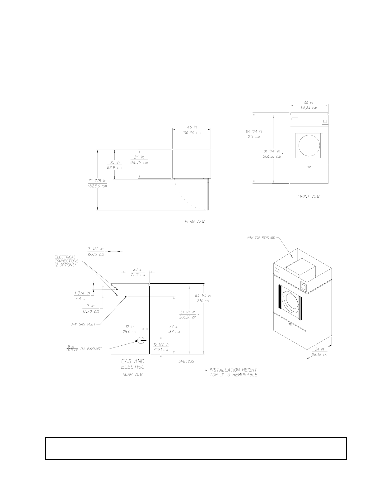
SPECIFICATIONS/COMPONENT IDENTIFICATION
A. SPECIFICATIONS
SECTION II
ASKET
B
ASKET
B
ASKET
B
OOR OPENING
D
ASKET
B
RYERS PER
D
RYERS PER
D
UMBLER
(T
UMBLER
(T
UMBLER
(T
(D
UMBLER
(T
20'/40'' C
45'/48' T
V
OLTAGE AVAI LABLE
PPROX
A
A
H
Gas
A
. W
PPROX
. W
EAT INPUT
IRFLOW
IAMETER
) D
EPTH
) D
OTOR
) M
IAMETER
) V
EIGHT (UNCRATED
EIGHT (CRATED
) 31-3/8" 79.7 cm
OLUME
ONTAINER
RUCK
)950 lbs.
)895 lbs.
Inlet Pipe Size 3/4"
OLTAGE AVAI LABLE
V
PPROX
A
PPROX
A
Electric
IRFLOW
A
OLTAGE AVAI LABLE
V
A
PPROX
PPROX
A
IRFLOW
A
OMPR ESSED AIR VOLUME
C
C
OMPR ESSED AIR CONNECTION
EIGHT (UNCRATED
. W
EIGHT (CRATED
. W
. W
EIGHT (UNCRATED
EIGHT (CRATED
. W
)895 lbs.
)950 lbs. 432 kg
)980 lbs
)1,130 lbs.
44-1/2"
24-7/8"
* .746 kw
1 HP
22.4 cu. ft .
113 cm
63.2 cm
.634 cu.m.
10/20
24/24
120 / 208 / 240 / 480v / 1, 3ø / 50/ 60Hz
407 kg
432 kg
204,000 bt u/hr
1, 200 cfm
51,408 kcal/hr
33.98 cmm
** 1.91 cm
120 / 208 / 240 / 480v / 1, 3ø / 50/ 60Hz
407 kg
1, 200 cfm
33.98 cmm
120 / 208 / 240 / 480v / 1, 3ø / 50/ 60Hz
445 kg
514 kg
1, 200 cfm
.75 cfh
1/8" F.P. T.
33.98 cmm
.02 cmh
.318 cm
OILER
B
Steam
Shaded areas are stated in metric equivalents.
TEAM COMSUMPTION
S
238.7 lb s/hr
PERATING STEAM PRESSURE
O
12 5 p si max
108.3 kg/hr
8.6 bar
N
S
1"
HP
ORMAL LOAD
7
TEAM SUPPLY
2.54 cm
TEAM RETURN
S
1"
2.54 cm
* For non- reversi ng model s.
A minimum of 3/4" pi pe mus t be suppli ed to the gas i nlet for e ach drye r.
**
IMPORTANT: Steam dryers must be provided with a clean, dry, regulated 80 PSI (+/- 10 PSI)
air supply.
NOTE: ADC reserves the right to make changes in specifications at any time, without notice or
obligation.
6
Page 11
Specifications*
ADG-78 (Gas)
ADE-78 (Electric)
* Specifications for the ADS-78 (steam model) were not availa ble at time of printing...for information contact
the factory.
NOTE: ADC reserves the right to make changes in specifications at any time, without notice or
obligation.
7
Page 12
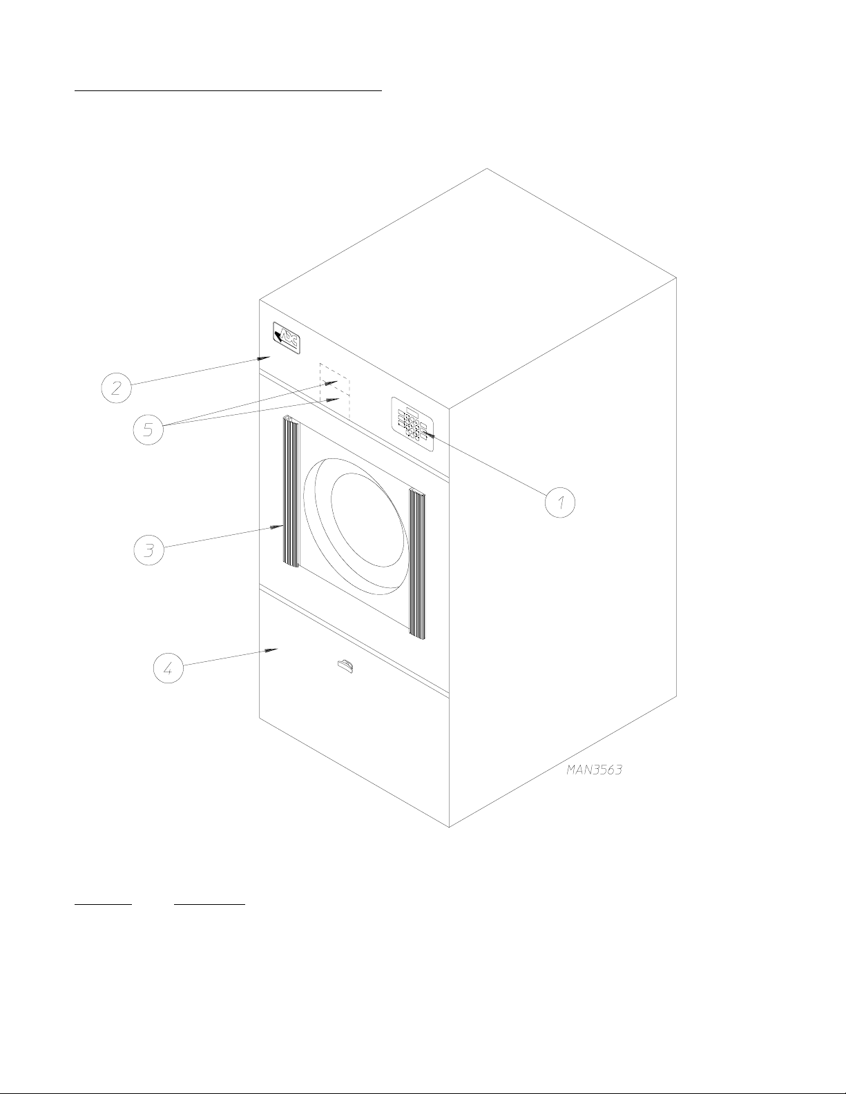
B. COMPONENT IDENTIFICATION
1. Dryer Front View
Illus. No. Description
1 Controls
2 Control (top access) Door Assembly
3 Main Door Assembly
4 Lint Compartment Area (lint screen located behind door)
5 Data Label and Installation Label (located behind control [service] door)
8
Page 13
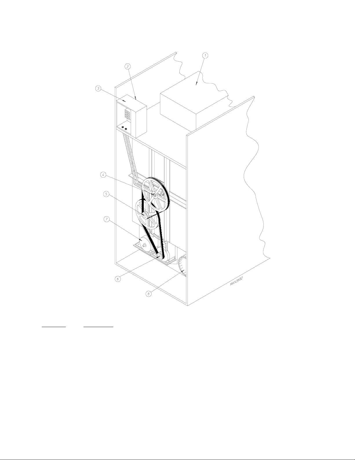
2. Dryer Rear View
Illus. No. Description
1 Heating Unit
2 1/8" Compressed Air Supply Inlet
(behind Electric Service Relay Box for Steam Models ONLY)
3* Electric Service Relay Box
4 Tumbler Bearing Mount Assembly
5 Idler Bearing Mount Assembly
6 Basket (Drive) Motor Assembly (for Reversing Models ONLY)
7 Blower Motor Assembly
8 Dryer Exhaust
* Electric service connections for Gas Models and Steam Models are made in this box.
9
Page 14
SECTION III
INSTALLATION PROCEDURES
Installation should be performed by competent technicians in accordance with local and state codes. In the
absence of these codes, the installation must conform to applicable American National Standards: National
Fuel Gas Code ANSI.Z223.1-LATEST EDITION and/or National Electric Code ANSI/NFPA NO. 70-LA TEST
EDITION.
A. LOCATION REQUIREMENTS
Before installing the dryer, be sure the location conforms to local codes and ordinances. In the absence of such
codes or ordinances the location must conform with the National Fuel Gas Code ANSI.Z223.1-LATEST
EDITION.
1. The dryer must be installed on a sound le v el floor capable of supporting its weight. It is recommended that
carpeting be removed from the floor area that the dryer is to rest on.
2. The dryer must not be installed or stored in an area where it will be exposed to water and/or weather.
3. The dryer is for use in noncombustible locations.
4. Provisions for adequate air supply must be provided as noted in this manual (refer to Fresh Air Supply in
Section D).
5. Clearance provisions must be made from combustible construction as noted in this manual (refer to Dryer
Enclosure Requirements in Section C).
6. Provisions must be made for adequate clearances for servicing and for operation as noted in this manual
(refer to Dryer Enclosure Requirements in Section C).
7. Dryer must be exhausted to the outdoors (refer to Exhaust Requirements in Section E).
8. Dryer must be located in an area where correct exhaust venting can be achieved as noted in the manual
(refer to Exhaust Requirements in Section E).
IMPORTANT: Dryer should be located where a minimum amount of exhaust duct will be
necessary.
10
Page 15
B. UNPACKING/SETTING UP
Remove protective shipping material (i.e., plastic wrap, and/or optional shipping box) from dryer.
IMPORTANT: Dryer must be transported and handled in an upright position at ALL times.
The dryer can be moved to its final location while still attached to the skid or with the skid remov ed. To un-skid
the dryer, locate and remo v e the four (4) bolts securing the base of the dryer to the wooden skid. Two (2) are at
the rear base (remove the back panel for access), and two (2) are located in the bottom of the lint chamber. To
remove the two (2) bolts located in the lint chamber area, remove the lint door.
To increase bearing life and improve efficiency, the dryer should be tilted slightly to the rear.
The basket (tumbler) is supported during shipping by a wooden block. REMOVE THIS BLOCK BEFORE
STARTING THE DRYER.
IMPORTANT: For microprocessor (computer) models, this wooden block must be remov ed
before connecting power to the dryer or irreparable damage to the basket
(tumbler) will result.
The lint coops of ALL AD-78 dryers are supported during shipping by a bracket. REMOVE THIS BRACKET
BEFORE STAR TING THE DR YER.
11
Page 16
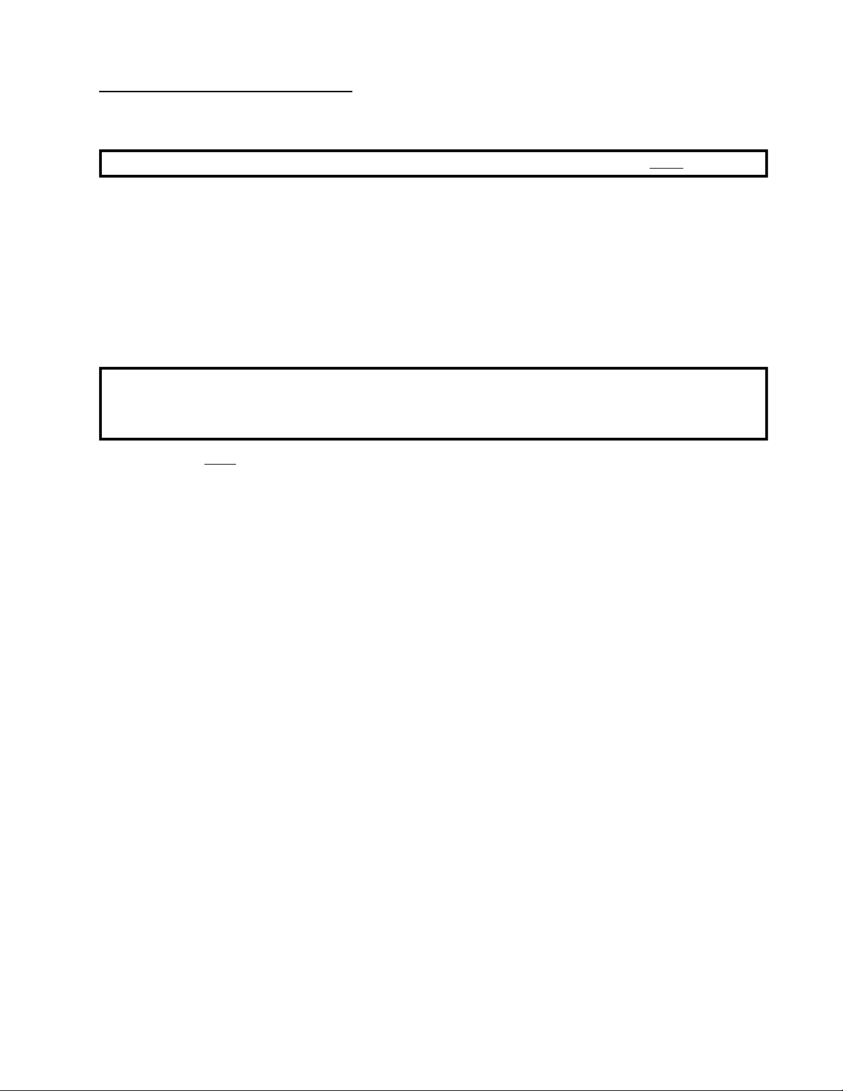
C. DRYER ENCLOSURE REQUIREMENTS
Bulkheads and partitions should be made of noncombustible materials and must be located a minimum of
twelve (12) inches (18-inches or more is recommended for ease of installation, maintenance , and service) above
the dryer outer top, except along the front of the dryer which may be partially closed in if desired. The clearance
between the bulkhead header and the dryer must be a minimum of four (4) inches and must not extend more
than four (4) inches to the rear of the front. The bulkhead facing must not be closed in all the way to the top of
the dryer. A one (1) inch clearance is required.
NOTE: Allowances must be made for opening the control door.
Dryers may positioned side wall to side wall. Howev er , a 1/16" minimum allow ance must be made for opening
and closing of the control door and the lint door. It is suggested that the dryer be positioned about two (2) feet
away from the nearest obstruction for ease of installation, maintenance, and service (to be measured from the
back guard. (Refer to the illustration above for details.)
NOTE: Air considerations are important for proper and ef ficient operation.
12
Page 17
IMPORTANT: Even though a minimum of only 12-inches is required, 18-inches or more is
suggested. The additional clearance is advantageous for ease of installation
and service.
IMPORTANT: When fire sprinkler systems are located above the dryers, a minimum of
18-inches above the dryer console (module) is required. Dryers may be
positioned side wall to side wall however, a 1/16" minimum allowance is
required between dryers (or wall) for ease of installation and maintenance.
Allowances must be made for the opening and closings of the control door
and the lint door.
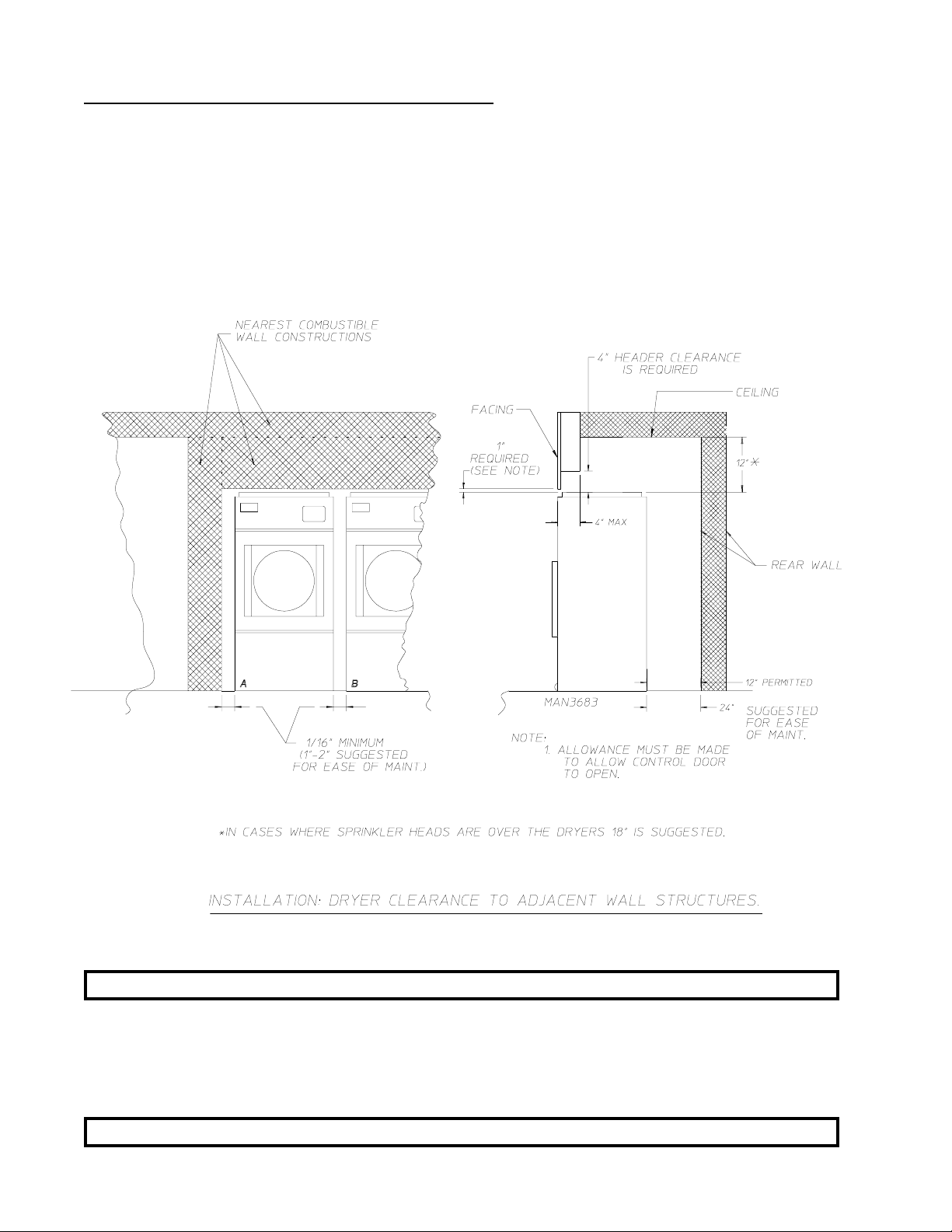
D. FRESH AIR SUPPLY
When the dryer is operating, it draws in room air, heats it, passes this air through the basket (tumbler), and
exhausts it out of the building. Therefore, the room air must be continually replenished from the outdoors. If
the make-up air is inadequate, drying time and drying efficiency will be adversely affected. Ignition problems
and sail switch "fluttering" problems may result, as well as premature motor failure from overheating.
Air supply (make-up air) must be given careful consideration to assure proper performance of each dryer. An
unrestricted source of air is necessary for each dryer. An air flow of 1,200 cfm (cubic feet per minute) must be
supplied to each gas and electric dryer and 1,350 cfm (cubic feet per minute) must be supplied to each steam
dryer. As a general rule, an unrestricted air entrance from the outdoors (atmosphere) of a minimum of 1-1/2
square feet is required for each dryer.
13
Page 18
T o compensate for the use of re gisters or louvers used ov er the openings, this make-up air must be increased by
approximately thirty-three percent (33%). Make-up air openings should not be located in an area directly near
where exhaust vents exit the building.
It is not necessary to have a separate make-up air opening for each dryer. Common make-up air openings are
acceptable. However, they must be set up in such a manner that the make-up air is distributed equally to
the dryers.
EXAMPLE: For a bank of four (4) dryers, two (2) unrestricted openings measuring 2 feet by 1-1/2 feet
(6 square feet) is acceptable.
Allowances must be made f or remote or constricting passageways or where dryers are located at excessive
altitudes or predominantly low pressure areas.
ALL
IMPORTANT: Make-up air must be provided from a source free of dry cleaning solvents
fumes. Make-up air that is contaminated by dry cleaning solvent fumes will
result in irreparable damage the motors and other dryer components.
NOTE: Component failure due to dry cleaning solvent fumes will VOID THE WARRANTY.
14
Page 19
E. EXHAUST REQUIREMENTS
1. General Exhaust Duct Work Information
Exhaust duct work should be designed and installed by a qualified professional. Improperly sized duct
work will create excessiv e back pressure which results in slo w drying, increased use of ener gy, overheating
of the dryer, and shutdown of the b u rner by the airflow (sail) s witches, b urner hi-limits, or basket (tumbler)
hi-heat thermostats.
CAUTION: DRYER MUST BE EXHAUSTED TO THE OUTDOORS.
CAUTION: IMPROPERLY SIZED OR INSTALLED EXHAUST DUCT WORK CAN
CREATE A POTENTIAL FIRE HAZARD.
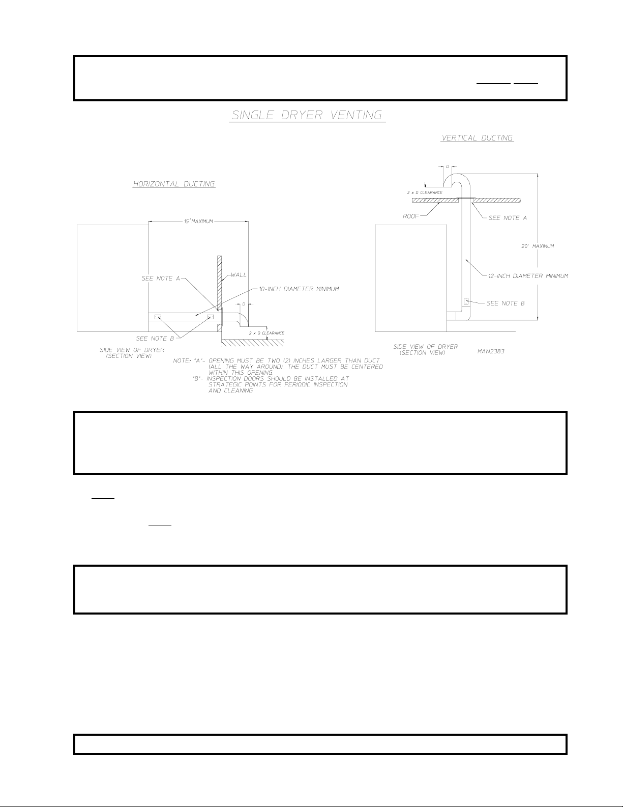
The duct work should be laid out in such a way that the duct work travels as directly as possible to the outdoors with as few turns as possible. Single or independent dryer venting is recommended.
Horizontal V enting:
When single drying venting is used the length of duct work from the dryer to the outside exhaust outlet
should not exceed fifteen (15) feet. The minimum diameter of this duct work must be at least 10-inches
(even though the dryer exhaust duct for gas and electric dryers is only 8-inches). In the case of multiple
(common) dryer venting, the distance from the last dryer to the outside exhaust outlet should not exceed
(15) feet. The shape of the duct work is not critical so long as the minimum cross-sectional area is provided.
It is suggested that the use of 90° turns be avoided; use 30° and/or 45° angles instead. The radius of the
elbows should preferably be 1-1/2 times the diameter of the duct. Including basket (tumbler)/dryer elbow
connections or elbows used for outside protection from the weather, no more than two (2) elbo ws should be
used in the exhaust duct run. If more than two (2) elbows are used, the cross sectional area of the duct work
must be increased. ALL duct work should be smooth inside with no projections from sheet metal screws
or other obstructions which will collect lint. When adding ducts, the duct to be added should overlap the
duct to which it is to be connected. ALL duct work joints must be taped to prevent moisture and lint from
escaping into the building. Inspection door should be installed at strategic points in the exhaust duct work
for periodic inspection and clean-out of lint from the duct work.
Vertical Venting:
When single dryer venting is used the length of the duct work from the dryer to the outside exhaust outlet
should not exceed twenty (20) feet. The minimum diameter of this duct work must be at least 12- inches
(even though the dryer exhaust duct for gas and electric units is only 8-inches). In the case of multiple
(common) dryer venting, the distance from the last dryer to the outside exhaust outlet should not exceed
twenty (20) feet. The shape of the duct work is not so critical so long as the minimum cross sectional area
is provided. It is suggested that the use of 90º turns be avoided; use 30º and/or 45º bends instead . The radius
of the elbows should preferably be 1-1/2 times the diameter of the duct. ALL duct work should be smooth
inside with no projections from sheet metal screws or other obstructions which will collect lint. When
adding ducts, the duct to be added should overlap the duct to which it is to be connected. ALL duct work
joints must be taped to prevent moisture and lint from escaping into the building. Inspection door should
be installed at strategic points in the exhaust duct work for periodic inspection and clean-out of lint from the
duct work.
IMPORTANT: Exhaust back pressure measured by a manometer in the exhaust duct should
not exceed 0.3 inches of water column.
15
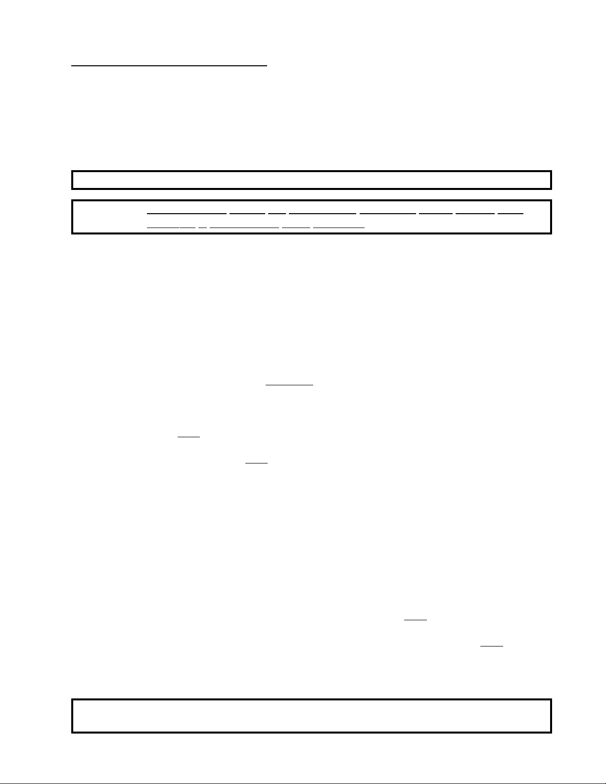
Page 20
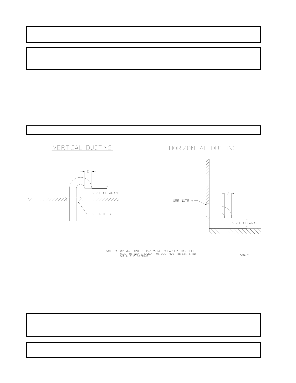
IMPORTANT: Minimum duct work diameter for horizontal venting is 10-inches and for vertical
venting the minimum is 12-inches.
NOTE: Where the exhaust duct work passes through a wall, ceiling, or roof made of combustible
materials, the opening must be 2-inches larger (all the way around) than the duct. The
duct must be centered within this opening.
a. Outside Duct Work Protection
1) To protect the outside end of horizontal duct work from the weather, a 90° elbow bent downward
should be installed where the exhaust exits the building. If the duct work travels vertically up
through the roof, it should be protected from the weather by using a 180° turn to point the opening
downward. In either case, allow at least twice the diameter of the duct between the duct opening and
the nearest obstruction.
IMPORTANT: DO NOT use screens or caps on the outside of opening of e xhaust duct work.
2. Single Dryer Venting
Where possible, it is suggested to provide a separate exhaust duct for each dryer. The exhaust duct should
be laid out in such a way that the duct work travels as directly as possible to the outdoors with as fe w turns
as possible. It is suggested that the use of 90° turns in the ducting be avoided; use 30° and/or 45° angles
instead. The shape of the exhaust duct work is not critical so long as the minimum cross section area is
provided.
IMPORTANT: Minimum duct size for a dryer that is vented horizontally is 10-inches for a
round duct or an equivalent of 80 square inches. THE DUCT SIZE MUST
NOT BE REDUCED ANYWHERE DOWN STREAM OF THE DRYER.
IMPORTANT: Exhaust back pressure measured by a manometer at each basket (tumbler)
exhaust duct area should not exceed 0.3 inches of water column.
16
Page 21
IMPORTANT: Minimum duct size for a dryer that is vented vertically is 12-inches for a round
duct or an equivalent of 120 square inches. THE DUCT SIZE MUST NOT BE
REDUCED ANYWHERE DOWN STREAM OF THE DRYER.
IMPORTANT: For extended duct work runs, the cross section area of the duct w o rk can only be
increased to an extent. When the duct work approaches the maximum limits
noted in this manual, a professional heating venting air conditioning (HVAC)
firm should be consulted for proper venting information.
ALL duct work should be smooth inside with no projections from sheet metal screws or other obstructions
which will collect lint. When adding ducts, the duct to be added should ov erlap the duct to which it is to be
connected. ALL duct work joints must be taped to prevent moisture and lint from escaping into the
building. Inspection doors should be installed at strategic points in the exhaust duct work for periodic
inspection and clean-out of lint from the duct work.
NOTE: Where the exhaust duct passes through a wall, ceiling, or roof made of combustible
materials, the opening must be 2-inches larger (all the way around) than the duct. The
duct must be centered within this opening.
a. Outside Duct Work Protection
1) To protect the outside end of horizontal duct work from the weather, a 90° elbow bent downward
should be installed where the exhaust exits the building. If the duct work travels vertically up
through the roof, it should be protected from the weather by using a 180° turn to point the opening
downward. In either case, allow at least twice the diameter of the duct between the duct opening and
the nearest obstruction.
IMPORTANT: DO NOT use screens or caps on the outside of opening of e xhaust duct work.
17
Page 22
18
Page 23
F. ELECTRICAL INFORMATION
1. Electrical Requirements
It is your responsibility to have ALL electrical connections made by a properly licensed and competent
electrician to assure that the electrical installation is adequate and conforms with local and state regulations
or codes. In the absence of such codes, ALL electrical connections, material, and workmanship must
conform to the applicable requirements of the National Electrical Code ANSI/NFPA NO.70-LATEST
EDITION..
IMPORTANT: Failure to comply with these codes or ordinances, and/or the requirements
stipulated in this manual can result in personal injury or component failure.
NOTE: Component failure due to improper installation will VOID THE WARRANTY.
Each dryer should be connected to an independently protected branch circuit. THE DRYER MUST BE
CONNECTED WITH COPPER WIRE ONLY. DO NOT use aluminum wire which could cause a fire
hazard. The copper conductor wire/cable must be of proper ampicity and insulation in accordance with
electric codes for making ALL service connections.
NOTE: The use of aluminum wire will VOID THE WARRANTY.
IMPORTANT: A se parate circuit servicing each dryer must be provided.
19
Page 24

2. Electrical Service Specifications
LECTR IC SERVICE SPECIFICATIONS
E
ADG-78 (Gas)
ADS-78 (Steam)
(per dryer)
I MPORTAN T
NOTE
SERVICE
VOLTAGE
120 1ø 2 13 #10 20 25
208 1ø 2 8 #14 12 15
208 3ø 3 5 #14 8 15
230 1ø 2 7 #14 10 15
230 3ø 3 5 #14 8 15
240 1ø 2 7 #14 10 15
380-400 3ø 3 3 #14 5 15
416 3ø 3 3 #14 5 15
460 3ø 3 3 #14 5 15
: 208 V AC and 230/240 VAC
: A. F use rati ngs are dua l-element, ti me-de lay, current l imiting, class RK1 or RK5
B. Cir cuit b reak ers ar e th ermal m agn etic (i ndus trial ) ty pe
ac cording to app liance a mp draw ratin g and type of breaker used.
C. Circuit breakers for 3-phase dryers
PHA SE
WIRE
SERVICE
AR E NOT THE SAM E. When o rdering, specify exact voltage.
ONLY
.
ONLY
. For oth ers, calc ulate/verify corr ect breaker s ize
mu st b e
AMP DRAW
3-pole type.
APPROX.
MINIMUM
WIRE SIZE*
FUS ING
Dual Element
Time Delay
CIRCU IT
BREAKER
IMPORTANT: The dryer must be connected to the electric supply shown on the data label that
is affixed to the back of the dryer, at the upper right hand corner. In the case of
208 VAC or 230/240 VAC, the supply voltage must match the electric service
specifications of the data label exactly.
IMPORTANT: The wire size must be properly sized to handle the related current.
WARNING: 208 VAC and 230/240 VA C ARE NOT THE SAME. Any damage done to dryer
components due to improper voltage connections will automatically VOID THE
WARRANTY.
NOTE: For electrically heated and steam models, contact the factory for electrical service
specifications.
NOTE: ADC reserves the right to make changes in specifications at any time, without notice or
obligation.
20
Page 25

3. Grounding
A ground (earth) connection must be provided and installed in accordance with state and local codes. In
the absence of these codes, grounding must conform to applicable requirements of the National Electric
Code ANSI/NFPA NO. 70-LATEST EDITION. The ground connection may be to a proven earth ground at
the location service panel.
For added personal safety, when possible, it is suggested that a separate ground wire (no. 18 minimum) be
connected from the ground connection of the dryer to a grounded cold water pipe. DO NOT ground to a gas
pipe or hot water pipe. The grounded cold water pipe must have metal to metal connection all the way to
the electrical ground. If there are any non-metallic interruptions, such as, a meter , pump, plastic, rubber, or
other insulating connectors, they must be jumped out with no. 4 copper wire and securely clamped to bare
metal at both ends.
IMPORTANT: For personal safety and proper operation, the dryer must be grounded.
Provisions are made for ground connection in each dryer at the electrical service connection area.
4. Electrical Connections
NOTE: A wire diagram is located in the front electrical control box for connection data.
a. GAS MODELS and STEAM MODELS ONL Y
NOTE: A CIRCUIT SERVING EACH DRYER MUST BE PROVIDED.
1) Single-phase (1ø) Wiring Connections (Hookup)
The electrical connections on
into the rearservice box located at the upper left area of the dryer.
ALL single-phase (1ø) gas models and steam model dryers are made
21
Page 26

Connect L1 and L2 to the power block and ground to the copper lug located
in the rear service box mentioned above.
S
INGLE-PHASE
LACK
B
+
OSITIVE
P
(1ø) E
LECTRICAL CONNECTI ON LEADS
HITE
W
+
EUTRAL
N
OR
G
ROUND
G
REEN
+
L2
If local codes permit, power to the dryer can be made by the use of a flexible U.L. listed po wer cord/
pigtail (wire size must conform to rating of dryer), or the dryer can be hard wired directly to the
service breaker panel. In both cases, a strain relief must be installed where the wiring enters the
dryer.
b. 3-Phase (3
The electrical connections on
ø) Wiring Connections (Hookup) - for NON-REVERSING MODELS ONLY
ALL 3-phase (3ø) gas model and steam model dryers are made into the
rear service box located at the upper left area of the dryer. Electrical connections for electrically heated
dryers are made in the electric oven area located at the upper rear area of the dryer.
NOTE: A CIRCUIT SERVING EACH DRYER MUST BE PROVIDED.
If local codes permit, power to a gas or steam dryer can be made by the use of a flexible U.L. listed power
cord/pigtail (wire size must conform to rating of dryer), or the dryer can be hard wired directly to the
service breaker panel. In
ALL cases, a strain relief must be installed where the wiring enters the dryer.
22
Page 27

1) GAS MODELS and STEAM MODELS ONLY
The only electrical input connections to the dryer are the 3-phase (3ø) power leads (L1,L2,L3 and
sometimes neutral) and ground. Single-phase (1 ø) power for the control circuit is done internally to
the dryer. No single-phase (1ø) input connection is required on a 3-phase (3ø) dryer.
For gas and steam dryers manufactured for operation at 3-phase (3ø), the electrical connections are
made at the power distribution block located in the service box at the rear, upper left corner of the
dryer. The ground connection is made to the copper lug also provided in this box. To gain access to
the service box contactor, the service box cover must be removed.
23
Page 28

1) ELECTRICALL Y HEATED MODELS ONLY
The only electrical input connections to the dryer are the 3-phase (3ø) power leads (L1,L2,L3 and
sometimes neutral) and ground. Single-phase (1ø) power for the control circuit is done internally to
the dryer. No single-phase (1ø) input connection is required on a 3-phase (3ø) dryer.
CAUTION: The dryer must be grounded. A ground lug has been provided for this purpose.
Input connection wiring must be sized properly to handle the dryer's current draw. This information
is printed on the dryers data label.
NOTE: A CIRCUIT SERVING EACH DRYER MUST BE PROVIDED.
The electrical input connections are made at the electric oven contactor located inside the assembly at
the rear center upper section of the dryer. The ground connection is made to a copper lug also
provided in this area. To gain access, remove oven rear service cover.
IMPORTANT: A strain relief must be used where the input wiring enters the oven assembly.
24
Page 29

c. 3-Phase (3
ø) Wiring Connections (Hookup) - for REVERSING MODELS ONLY
The electrical connections on
rear service box located at the upper left area of the dryer. Electrical connections for electrically heated
dryers are made in the electric oven area located at the upper rear area of the dryer.
ALL 3-phase (3ø) gas model and steam model dryers are made into the
NOTE: A CIRCUIT SERVING EACH DRYER MUST BE PROVIDED.
If local codes permit, power to a gas or steam dryer can be made by the use of a flexible U.L. listed power
cord/pigtail (wire size must conform to rating of dryer), or the dryer can be hard wired directly to the
service breaker panel. In
The only electrical input connections to the dryer are the
3-phase (3ø) power leads (L1,L2,L3 andsometimes neutral)
and ground. Single-phase (1ø)power for the control circuit
is done internally to the dryer. No single-phase (1ø) input
connection is required on a 3-phase (3ø) dryer.
ALL cases, a strain relief must be installed where the wiring enters the dryer.
For gas model and steam model dryers manufactured for
operation at 3-phase (3ø), the electrical connections are made
at the power distribution block located in the service box at
the rear, upper left corner of the dryer. The ground
connection is made to the copper lug also provided in this
box. To gain access to the service box contactor, the service
box cover must be removed.
25
Page 30

G. GAS INFORMATION
It is your responsibility to have ALL plumbing connections made by a qualified professional to assure that the
gas plumbing installation is adequate and conforms with local and state regulations or codes. In the absence of
such codes, ALL plumbing connections, materials, and workmanship must conform to the applicable
requirements of the National Fuel Gas Code ANSI Z223.1-LATEST EDITION.
IMPORTANT: Failure to comply with these codes or ordinances, and/or the requirements
stipulated in this manual, can result in personal injury and improper operation
of the dryer .
The dryer and its individual shut-off v alves must be disconnected from the gas supply piping system during any
pressure testing of that system at test pressures in excess of 1/2 psig (3.5 kPa). The dryer must be isolated from
the gas supply piping system by closing its individual manual shut-off v alve during any pressure test of the gas
supply system at test pressures equal to or less than 1/2 psig (3.5 kPa).
IMPORTANT: Failure to isolate or disconnect dryer from supply as noted can cause irreparable
damage to the gas valve which will VOID THE WARRANTY.
WARNING: FIRE or EXPLOSION COULD RESULT.
1. Gas Supply
The gas dryer installation must meet the American National Standard...National Fuel Gas Code
ANSI Z223.1-LATEST EDITION, as well as local codes and ordinances and must be done by a qualified
professional.
NOTE: Undersized gas piping will result in ignition problems, slow drying, increased use of
energy, and can create a safety hazard.
The dryer must be connected to the type of heat/gas indicated on the dryer label affixed behind the right
control box door. If this information does not agree with the type of gas available, DO NOT operate the
dryer. Contact the distributor who sold the dryer or the ADC factory.
IMPORTANT: Any burner changes or con versions must be made by a qualified professional.
The input ratings shown on the dryer data label are for elevations up to 2,000 feet, unless elevation
requirements of over 2,000 feet were specified at the time the dryer order was placed with the factory. The
adjustment or conversion of dryers in the field for elevations over 2,000 feet are made by changing each
burner orifice. If this con v ersion is necessary , contact the distrib utor who sold the dryer or contact the ADC
factory .
26
Page 31

2. Technical Gas Data
a. Gas Specifications
Natural Gas Liquid Propane Gas
Manifold Pressure* 3.5 - 4.0 i nches W.C. 10.5 - 11. 0 inches W.C.
Inline Pressure 6.0 - 12. 0 inches W.C. 11.0 inches W.C .
* Measured at the gas valve p ressu re tap when the gas valv e is on.
b. Gas Connections:
Inlet connection ---------- 3/4-inch N.P.T.
Inlet supply size ---------- 3/4-inch N.P.T. (minimum)
Btu/hr input (per dryer) - 204,000
1) Natural Gas
Type of Gas
Regulation is controlled by the dryer's gas valve's internal re gulator . Incoming supply pressure must
be consistent between a minimum of 6.0 inches and a maximum of 12.0 inches water column (W.C.)
pressure.
2) Liquid Propane (L.P.) Gas
Dryers made for use with L.P. gas have the gas valve's internal pressure regulator blocked open so
that the gas pressure must be regulated upstream of the dryer. The pressure measured at each gas
valve pressure tap must be a consistent 11.0 inches water column (W.C.). There is no regulator or
regulation provided in an L.P. dryer. The water column pressure must be regulated at the source (L.P.
tank) or an external regulator must be added to each dryer.
Type of Gas
Conversion
Part Number
MODEL
NUMBER
BTU
Per Hour
Rating
Qty. D.M.S.*
Natural Liquid Propane
Part
Part
Qty. D.M.S.*
Number
Number
ADG-78 204,000 4 #29 140820 4 #47 140805 881655
* D.M .S. ( Drill Material Size ) equival ents are a s follo ws:
L.P.
Kit
Natural Gas ................
Liquid Propane Gas ...
#29 = .1360"
#47 = .0785"
27
Page 32

3. Piping/Connections
ALL components/materials must conform to National Gas Code specifications. It is important that gas
pressure regulators meet applicable pressure requirements and that gas meters be rated for the total amount
of ALL the appliance BTU's being supplied.
The dryer is provided with a 3/4" N.P.T. inlet pipe connection located at the right side of the base of the
dryer. The minimum pipe size (supply line) to the dryer is 3/4" N.P.T. For ease servicing, the gas supply
line of each dryer must have its own shut-off valve.
The size of the main gas supply line (header) will vary depending on the distance this line travels from the
gas meter or, in the case of L.P. (liquid propane) gas, the supply tank, other gas-operated appliances on the
same line, etc. Specific information regarding supply line size should be determined by the gas supplier.
NOTE: Undersized gas supply piping can create a low or inconsistent pressure which will result
in erratic operation of the burner ignition system.
28
Page 33

Consistent gas pressure is essential at ALL gas connections. It is recommended that a 2-inch pipe gas loop
be installed in the supply line serving a bank of dryers. An in-line pressure re gulator must be installed in the
gas supply line (header) if the (natural) gas pressure exceeds 12.0 inches of water column pressure.
NOTE: A water column test pressure of 3.5-4.0 inches for natural gas and 11.0 inches for L.P.
(liquid propane) dryers is required at the gas valve pressure tap of each dryer for proper
and safe operation.
A 1/8" N.P.T. plugged tap, accessible for a test gauge connection, must be installed in the main gas supply
line immediately upstream of each dryer.
IMPORTANT: Pipe joint compounds that resist the action of natural gas and L.P. gas must be
used.
IMPORTANT: Test ALL connections for leaks by brushing on a soapy w a ter solution (liquid
detergent works well).
WARNING: NEVER TEST FOR LEAKS WITH A FLAME!!!
ALL components/materials must conform to National Gas Code specifications. It is important that gas
pressure regulators meet applicable pressure requirements and that gas meters be rated for the total amount
of ALL the appliance BTU's being supplied.
IMPORTANT: The dryer and its individual shut-off valve must be disconnected from the gas
supply piping system during any pressure testing of that system at test pressures
in excess of 1/2 psig (3.5 kPa).
NOTE: The dryer must be isolated from the gas supply piping system by closing its individual
manual shut-off valve during any pressure test of the gas supply system at test pressures
equal to or less than 1/2 psig (3.5 kPa).
29
Page 34

H. STEAM INFORMATION
It is your responsibility to have ALL plumbing connections made by a qualified professional to assure that the
gas plumbing installation is adequate and conforms with local and state regulations or codes.
IMPORTANT: Failure to comply with the requirements stipulated in this manual can result in
component failure which will VOID THE WARRANTY.
NOTE: The ADS-78 is manuf actured with a pneumatic (piston) damper system which requires
an external supply of clean, dry, regulated air (80 PSI +/- 10 PSI).
1. Steam Coil PH Level
The normal PH level for copper type steam coils must be maintained between a value of 8.5 to 9.5.
For steel type steam coils the PH level must be maintained between a value of 9.5 to 10.5. These
limits are set to limit the acid attack of the steam coils.
IMPORTANT: Coil failure due to improper PH level will VOID THE WARRANTY.
2. Steam Requirements - High Pressure
Inlet -------- 1" supply line connection -- qty. one (1) at top manifold.
Return ----- 1" return line connection --- qty. one (1) at bottom manifold.
Operating Steam Pressure
Maximum 125 psig
Minimum 100 psig
Heat I nput (Normal Load) 7 Bhp
Consumption (approximate) 239 lbs /hr
3. Installation Instructions
To insur e an adequate supply of steam is provided, be sure that the steam lines and steam return lines are
sized and laid out as stipulated in this manual. Inadequate steam lines and steam return lines or improper
steam plumbing will result in poor performance and can cause component failure. Clean, dry steam must
be provided to the dryer.
IMPORTANT: Steam coil failure due to water hammer by wet steam will VOID THE
WARRANTY.
a. The pressure of the condensate in the steam supply will cause water hammer and subsequent heat
exchanger (steam coil) failure. The steam supply connection into the main supply line must be made
with a minimum 12-inch riser. This will prevent any condensate from draining towards the dryer.
b. The steam supply piping to the dryer must include a 12-inch rise along with a drip trap and check valve.
This will prevent any condensate from entering the steam coil.
30
Page 35

c. Flexible hoses or couplings must be used. The dryer vibrates slightly when it runs and this will cause
the steam coil connections to crack if they are hard piped to the supply and return mains.
d. Shut-off valves for each dryer should be installed in the supply line, return line, and drip trap return line.
This will allow the dryer to be isolated from the supply main and the return main if the dryer needs
maintenance work.
e. Install an inverted bucket steam trap and check valve at least 12-inches below the steam coil as close to
the coil as possible.
1) A trap with capacity of 1,200 pounds of condensate per hour at 125 psi is needed for each unit.
f. The supply line and the return line should be insulated. This will save energy and provide for the safety
of the operator and maintenance personnel.
g. Water pockets in the supply line, caused by low points, will provide wet steam to the coil possibly
causing steam coil damage.
every one (1) foot back tow ards the steam supply header causing the condensate in the line to drain to the
header. Install a bypass trap in any low point to eliminate wet steam.
ALL horizontal runs of steam supply piping should be pitched 1/4-inch for
STEAM DAMPER SYSTEM
31
Page 36

4. Steam Damper Air System Connections
The ADS-78 is manufactured with a pneumatic (piston) damper system which requires an external supply
of compressed air. The air connection is made to the steam damper solenoid valve which is located at the
rear inner top area of the dryer just in front of the electric service relay box.
MAN2497
a. Air Requirements
Compress ed Air Supply Air Pres sure
Normal 80 PSI
Minimum Supply 70 PSI
Maximum Supply 90 PSI
b. Air Connection
Air connection to system --- 1/8-inch N.P.T.
c. No air regulator or filtration is provided with the dryer. External regulation/filtration of 80 psi must be
provided. It is suggested that a regulator/filter gauge arrangement be added to the compressed air line
just before the dryer connection. This is necessary to insure that correct and clean air pressure is achie ved.
32
Page 37

5. Steam Damper System Operation
The ADS-78 steam damper shown in Diagram 1 in the illustration below, allows the coil to stay constantly
charged eliminating repeated expansion and contraction. When the damper is opened, the air immediately
passes through the already hot coil, providing instant heat to start the drying process. When the damper is
closed, ambient air is drawn directly into the basket (tumbler), allowing a rapid cool down (Diagram 2).
Diagram 1 shows the damper in the heating (open) mode, allowing heat into the tumbler.
Diagram 2 shows the damper in the cool down (closed) mode, pulling ambient air directly into the basket
(tumbler) without passing through the coils.
NOTE: With the dryer off or with no air supply, the steam damper is in cool down mode as
shown in Diagram 2.
33
Page 38

5. Steam Damper Air Piston (Flow Control) Operation Adjustment
Although the steam damper operation was tested and adjusted prior to shipping at 80 PSI, steam damper
operation must be checked before the dryer is put into operation. Refer to
steam damper operation. If steam damper adjustment is necessary, locate the flow control valve and make
the necessary adjustments as noted below.
page 33 or instructions to check
34
Page 39

I. PREPARATION FOR OPERATION/START-UP
The following items should be checked before attempting to operate the dryer:
1. Read ALL "CAUTION," "WARNING," and "DIRECTION" labels attached to the dryer.
2. Check incoming supply voltage to be sure that it is the same as indicated on the dryer data label affixed to
the back side of the top front control/service door. In the case of 208 VAC or 230/240 VAC THE SUPPLY
VOLTAGE MUST MA TCH THE ELECTRIC SER VICE EXACTLY.
3. GAS MODELS - check to assure that the dryer is connected to the type of heat/gas indicated on the dryer
data label.
4. GAS/ELECTRIC MODELS - the sail switch damper assembly was installed and pre-adjusted at the
factory prior to shipping. However, each sail switch adjustment must be
checked to assure that this important safety control is functioning.
5. GAS MODELS - be sure that ALL gas shut-off valves are in the open position.
6. Be sure ALL back panels (guards) and electric box covers have been replaced.
7. Check ALL service doors to assure that they are closed and secured in place.
8. Be sur e the lint drawer is securely in place.
9. Rota te the basket (tumbler/drum) by hand to be sure it moves freely.
10. Check bolts, nuts, screws, terminals, and fittings for security.
11. STEAM MODELS - check to insure air supply (80 PSI) is connected to the dryer.
12. STEAM MODELS - check to insure ALL steam shut-off valves are open.
13. STEAM MODELS - check steam damper operation.
14. Check tumbler bearing set screws to insure they are ALL tight.
35
Page 40

J. PREOPERATIONAL TESTS
ALL dryers are thoroughly tested and inspected before leaving the factory. However, a preoperational test
should be performed before the dryer is publicly used. It is possible that adjustments have changed in transit or
due to marginal location (installation) conditions.
1. Turn on electric power to the dryer.
a. Open ALL shut-off valves (for Gas Models and Steam Models ONLY)
2. Refer to the Operating Instructions for starting your particular model dryer.
a. Gas Models
1) When the dryer is first started (during initial start-up), the burner has a tendency not to ignite on the
first attempt. This is because the gas supply piping is f illed with air, so it may take a few minutes for
this air to be purged from the lines.
NOTE: During the purging period, check to be sure that ALL gas shut-off v alv es are open.
NOTE: Gas dryers are equipped with a Hot Surface Ignition (HSI) system which has internal
diagnostics. If ignition is not established within three times the heat circuit in the HSI
module will "LOCK-OUT" until it is manually reset. To reset the HSI system, open and
close the main door and restart the dryer.
2) A gas pressure test should be taken at the gas valve pressure tap of each dryer to assure that the wa ter
column pressure is correct and consistent.
NOTE: Water column pressure requirements (measured at the gas valve pressure tap)...
Natural Gas --------- 3.5 - 4.0 Inches W.C.
L.P. Gas ------------ 10.5 - 11.0 Inches W.C.
IMPORTANT: There is no regulator provided in an L.P. dryer. The water column pressure must
be regulated at the source (L.P. tank), or an external regulator must be added to
each dryer .
b. Steam Models
1) Check to insure that steam damper is functioning properly.
a) The steam damper should not "slam" (open or closed) when it reaches the end of (piston) travel.
Additionally, the steam damper should not bind and/or stop during travel. If either of these
conditions occur, the flow control must be adjusted. Refer to the illustration on page 34 for air
adjustment instructions.
36
Page 41

c. Electric Models
1) Check to insure that electric oven/contactor assembly is activating.
3. Make a complete operational check of
a. Door Switch(es)
b. Hi-Limit Thermostats
c. Sail Switch (for Gas Models and Electric Models ONLY)
ALL safety related circuits:
NOTE: To check for proper sail switch operation (for Gas Models and Electric Models ONLY),
open the main door and while holding main door switch plunger in, start the dryer.
Dryer should start but heat circuit should not be activated (on). If the heat system is
activated, the sail switch is improperly adjusted and must be adjusted by bending the
actuator arm of the sail switch toward the burner box. If the actuator arm is bent to far
toward the burner box of the dryer, the dryer may not have heat when needed. After any
adjustment to the sail switch, the above procedure must be repeated to verify proper
operation of the sail switch.
4. The dryer should be operated through one (1) complete cycle to assure that no further adjustments are
necessary and that ALL components are functioning properly.
IMPORTANT: The dryer basket (tumbler) is treated with a protective coating. ADC suggests
tumbling old clothes or material in the basket (tumbler), using a mild detergent
to remove the protective coating.
5. Make a complete operational check of ALL operating controls.
a. For microprocessor models check controller (computer) programs/selections...
1) Each microprocessor controller (computer) has been preprogrammed by the factory with the most
commonly used parameter (program) selections. If computer program changes are required, refer to
the computer programming manual which was shipped with the dryer.
6. Check the electric service phase sequence (3-phase [3ø] models only). While the dryer is operating, check
to see if the blower wheel (impeller/fan) is rotating in the proper direction. Looking from the front, the
blower wheel (impeller/fan) should spin in the clockwise (CW) direction. If it is, the phasing is correct. If
the phasing is incorrect, reverse two (2) of the three (3) leads at connections L1, L2, L3 of the po wer supply
to the dryer.
IMPORTANT: If the blower wheel (impellor/fan) is rotating in the wrong direction, this will not
only drastically reduce drying efficiency, but it can also cause premature
component failure.
37
Page 42

7. REVERSING MODELS ONL Y - basket (tumbler) dryer should never be operated with less than a 30 lb.
load (dry weight). The size of the load will affect the coast-down and
dwell (stop) times. The basket (tumbler) must come to a complete stop
before starting in opposite direction.
a. Microprocessor Models
1)
Spin Times and Stop Times are not adjustable in the Automatic Mode and have been preprogrammed
into the microprocessor controller (computer) for 120-seconds spin time and a 5-second dwell (stop)
time.
2) Spin Times and Stop Times are adjustable in the Manual (timed) Mode.
b. Dual Timer Models
1) Both dwell (stop) time and basket (tumbler) spin time are adjustable (refer to the illustration on
page 65.
8. Check to insure that ALL set screws (i.e., tumbler drive, idler, etc.) are tight.
K. PREOPERATIONAL INSTRUCTIONS
1. To start the dryer...
a. Microprocessor (computer) dryers...
1) The L.E.D. (light emitting diode) display will read "FILL".
2) Press the "E" on the touchpad of the keyboard.
3) The L.E.D. display will quickly show "Ld30", "F180". The dryer will start, and the L.E.D. display
will show "dr30".
Refer to the User's Manual for detailed operating instructions.
b. Dual Timer dryers...
1) Turn drying timer knob for a time of 20 minutes.
2) Select "High Temp."
3) Push "Push To Start" switch.
4) T o stop dryer, open the main door.
38
Page 43

L. SHUT DOWN INSTRUCTIONS
If the dryer is to be shut down (taken out of service) for a period of time, the following MUST BE performed;
1. Discontinue power to the dryer either at the external disconnect switch or the circuit breaker.
2. Discontinue the heat supply:
a. GAS MODELS ... discontinue the gas supply.
1) SHUT OFF external gas supply shut-off valve.
2) SHUT OFF internal gas supply shut-off valve located in the gas valve burner area.
a. STEAM MODELS ... discontinue the steam supply.
1) SHUT OFF external (location furnished) shut-off valve.
2) SHUT OFF internal steam valves in the supply lines and the return lines.
39
Page 44

SECTION IV
SERVICE/PARTS INFORMATION
A. SERVICE
1. Service must be performed by a qualified trained technician, service agency, or gas supplier. If
service is required, contact the distributor from whom the ADC equipment was purchased. If the
distributor cannot be contacted or is unknown, contact the ADC Service Department for a distributor
in your area.
NOTE: When contacting the ADC Service Department, be sure to give them the correct model
number and serial number so that your inquiry is handled in an expeditious manner.
B. PARTS
1. Replacement parts should be purchased from the distributor from whom the ADC equipment was
purchased. If the distributor cannot be contacted or is unknown, contact the ADC Parts Department
for a distributor in your area. Parts may also be purchased directly from the factory by calling the
ADC Parts Department at (508) 678-9010 or you may FAX in your order at (508) 678-9447.
NOTE: When ordering replacement parts from the ADC dealer or the ADC factory be sure to
give them the correct model number and serial number so that your parts order can be
processed in an expeditious manner.
40
Page 45

SECTION V
WARRANTY INFORMATION
A. RETURNING WARRANTY CARD(S)
1. Before any dryer leaves the ADC factory test area, a warranty card (ADC Part No. 112254) is placed
on the back side of the main door glass. These warranty cards are intended to serve the customer
where we record the individual installation date and warranty information to better serve you should
you file a warranty claim.
a. If a warranty card (ADC Part No. 112254) did not come with your dryer, contact the ADC
Warranty Department or ADC Service Department at (508) 678-9000.
B. PARTS
For a copy of the ADC commercial warranty covering your particular dryer(s), contact the ADC
distributor from whom you purchased the equipment and request dryer warranty form ADC
Part No. 450199. If the distributor cannot be contacted or is unknown, warranty information can be obtained
from the factory by contacting the ADC Warranty Department at (508) 678-9000.
NOTE: Whenever contacting the ADC factory for warranty information, be sure to have the dryer's
model number and serial number available so that your inquiry can be handled in an
expeditious manner.
C. RETURNING WARRANTY PARTS
ALL dryer or parts warranty claims or inquires should be addressed to the ADC Warranty Parts
Department. To expedite processing, the following procedures must be followed:
1. No parts are to be returned to ADC without prior written authorization ("Return Material
Authorization") from the factory.
NOTE: An R.M.A. ("Return Material Authorization") is valid for only sixty (60) days from date of
issue.
a. The R.M.A. issued by the factory, as well as any other correspondence pertaining to the returned
part(s), must be included inside the package with the failed merchandise.
41
Page 46

2. Each part must be tagged with the following information:
a. Model number and serial number of the dryer from which part was removed.
b. Nature of failure (be specific).
c. Date of dryer installation.
d. Date of part failure.
e. Specify whether the part(s) being returned is for a replacement, a credit, or a refund.
NOTE: If a part is marked for a credit or a refund, the invoice number covering the purchase of
the replacement part must be provided.
NOTE: Warranty tags (ADC Part No. 450064) are av ailable at "no charge" from ADC upon
request.
3. The company returning the part(s) must clearly note the complete company name and address on the
outside of the package.
4. ALL returns must be properly packaged to insure that they are not damaged in transit. Damage claims
are the responsibility of the shipper.
IMPORTANT: No replacements, credits or refunds will be issued for merchandise damaged in
transit.
5. ALL returns should be shipped to the ADC factory in such a manner that they are insured and a proof
of delivery can be obtained by the sender.
6. Shipping charges are not the responsibility of ADC. ALL returns should be "prepaid" to the
factory. Any "C.O.D. or "COLLECT" returns will not be accepted.
IMPORTANT: No replacements, credits, or refunds will be issued if the claim cannot be
processed due to insufficient information. The party filing the claim will be
notified in writing, either by "FAX" or "CERTIFIED MAIL - Return Receipt
Requested,” as to the information necessary to process claim. If reply is not
received by the ADC Warranty Department within thirty (30) days from the
FAX/letter date, then no replacement, credit, or refund will be issued, and the
merchandise will be discarded.
42
Page 47

SECTION VI
ROUTINE MAINTENANCE
A. CLEANING
A program and/or schedule should be established for periodic inspection, cleaning, and removal of lint from
various areas of the dryer, as well as throughout the duct work system. The frequency of cleaning
can best be determined from experience at each location. Maximum operating efficiency is dependent
upon proper air circulation. The accumulation of lint can restrict this air flow. If the guidelines in this
section are met, an ADC dryer will provide may years of efficient, trouble-free, and - most importantly safe operation.
WARNING: LINT FROM MOST FABRICS IS HIGHLY COMBUSTIBLE. THE
ACCUMULATION OF LINT CAN CREATE A POTENTIAL FIRE
HAZARD.
WARNING: KEEP DRYER AREA CLEAR AND FREE FROM COMBUSTIBLE
MATERIALS, GASOLINE, and OTHER FLAMMABLE VAPORS and
LIQUIDS.
NOTE: Suggested time intervals sho wn are for average usage which is considered six (6) to eight
(8) operational (running) hours per day.
SUGGESTED CLEANING SCHEDULE
EVERY THIRD or FOURTH LOAD
Clean the lint screen every third or fourth load. A clogged lint screen will cause poor dryer performance. The
lint screen is located behind the lint door in the base of the dryer. Open the lint door, brush the lint off of the
lint screen, and remove the lint. Inspect the lint screen and replace if torn.
NOTE: The frequency of cleaning the lint screens can best be determined from experience at
each location.
WEEKLY
Clean lint accumulation from the lint chamber, thermostat, and microprocessor temperature sensor
(sensor bracket) area.
WARNING: TO AVOID HAZARD OF ELECTRICAL SHOCK, DISCONTINUE
ELECTRICAL POWER SUPPL Y T O THE DRYER.
43
Page 48

STEAM DRYERS
Clean the steam coil fins. Suggest using compressed air and a vacuum cleaner with brush attachment.
NOTE: When cleaning steam coil fins, be careful not to bend the fins. If the fins are bent,
straighten by using a fin comb, which is available from any local air conditioning supply
house.
90 DAYS
1. Remove lint from around basket (tumbler), drive motors, and surrounding areas.
2. Remove lint from gas valve burner area with a dusting brush or vacuum cleaner attachment.
3. Clean any lint accumulation in and around both the blower and drive motor casing openings.
NOTE: To prevent damage, avoid cleaning or touching the hot surface ignitor assembly.
EVERY 6 MONTHS
Inspect and remove lint accumulation in customer furnished exhaust duct work system and from dryers
internal exhaust ducting.
NOTE: THE ACCUMULATION OF LINT IN THE EXHAUST DUCT WORK CAN
CREATE A POTENTIAL FIRE HAZARD.
NOTE: DO NOT OBSTRUCT THE FLO W OF COMBUSTION and VENTILATION AIR.
CHECK CUSTOMER FURNISHED BACK DRAFT DAMPERS IN THE EXHAUST
DUCT WORK. INSPECT and REMOVE ANY LINT ACCUMULATION WHICH
CAN CAUSE THE DAMPER TO BIND or STICK.
NOTE: A back draft damper that is sticking partially closed can result in slow drying and shut-
down of heat circuit safety switches or thermostats
NOTE: When cleaning the dryer cabinet(s), avoid using harsh abrasives. A product intended for
the cleaning of appliances is recommended.
B. ADJUSTMENTS
7 DAYS AFTER INSTALLATION and EVERY 6 MONTHS THEREAFTER
Inspect bolts, nuts, screws, (bearing set screws), non-permanent gas connections (unions, shut-off valves,
orifices, and grounding connections). Motor and drive belts should be examined. Cracked or seriously
frayed belts should be replaced. Tighten loose V-belts when necessar y. Complete operational check of
controls and valves. Complete operational check of ALL safety devices (door switches, lint drawer switch,
sail switch, burner and hi-limit thermostats).
44
Page 49

SECTION VII
TROUBLESHOOTING
WARNING: YOU MUST DISCONNECT and LOCKOUT THE ELECTRIC SUPPLY and
THE GAS SUPPLY or THE STEAM SUPPLY BEFORE ANY COVERS or
GUARDS ARE REMO VED FROM THE MA CHINE TO ALLOW ACCESS
FOR CLEANING, ADJUSTING, INSTALLATION, or TESTING OF ANY
EQUIPMENT per OSHA (Occupational Safety and Health Administr ation)
STANDARDS.
The information provided will help isolate the most probable component(s) associated with the difficulty
described. The experienced technician realizes, howe ver , tha t a loose connection or broken/shorted wire may be
at fault where electrical components are concerned .. not necessarily the suspect component itself. Electrical
parts should always be checked for failure before being returned to the factory.
IMPORTANT: When replacing blown fuses, the replacement must be of the exact rating as the
fuse being replaced. The information provided should not be misconstrued as a
handbook for use by an untrained person in making repairs.
WARNING: ALL SERVICE and TROUBLESHOOTING SHOULD BE PERFORMED BY A
QUALIFIED PROFESSIONAL or SERVICE AGENCY.
WARNING: WHILE MAKING REPAIRS, OBSERVE ALL SAFETY PRECAUTIONS
DISPLAYED ON THE DRYER or SPECIFIED IN THIS MANUAL.
TABLE OF CONTENTS
(FOR TROUBLESHOOTING)
MICROPROCESSOR (COMPUTER) MODELS
ITEM PAGE
NO L.E.D. DISPLAY .............................................................................................. A 47
DRIVE MOTOR DOES NOT START ............................................................................ B 47
DRIVE MOTOR (REVERSING MODELS ONLY) OPERATES IN ONLY ONE DIRECTION ............ C 47
DRIVE MOTOR OPERATES FOR A FEW MINUTES THEN STOPS ................................... D 47
BLOWER/FAN MOTOR (REVERSING MODELS ONLY) DOES NOT START ............................. E 48
BLOWER/FAN MOTOR (REVERSING MODELS ONLY) OPERATES FOR A FEW MINUTES
THEN STOPS ....................................................................................................... F 48
BLOWER MOTOR AND FAN MOTOR (REVERSING MODELS ONLY) BOTH DO NOT START .... G, H 48
BLOWER MOTOR AND FAN MOTOR (REVERSING MODELS ONLY) OPERATES FOR A FEW
MINUTES AND BOTH STOP ................................................................................... I 48, 49
L.E.D. DISPLAY R EADS "dSFL" ............................................................................. J AND P 49 AND 50
L.E.D. DISPLAY READS "door" ............................................................................... K, L 49
45
Page 50

MICROPROCESSOR (COMPUTER) MODELS (CONTINUED)
ITEM PAGE
MICROPROCESSOR CONTROLLER (COMPUTER) WILL NOT ACCEPT ANY KEYBOARD
(KEYPAD) ENTRIES ................................................................................................ M 49
MICROPROCESSOR CONTROLLER (COMPUTER) WILL ONLY ACCEPT CERTAIN KEYBOARD
(KEYPAD) ENTRIES ................................................................................................ N 49
MICROPROCESSOR CONTROLLER (COMPUTER) LOCKS UP ............................................. O 50
DRYER STOPS DURING CYCLE AND L.E.D. DISPLAY RETURNS TO "FILL" ................ Q 50
L.E.D. DISPLAY READS "SEFL" ............................................................................ R 50
L.E.D. DISPLAY READS "HOT" ............................................................................... S 50
HEATING UNIT IS NOT OPERATING ........................................................................... T, U, V 51, 52, 53
DRYER IS TAKING TO LONG TO DRY ....................................................................... W 53 THRU 55
"Auto Cycle" OVER DRYING .................................................................................. X 55
"Auto Cycle" UNDER DRYING ................................................................................ Y 55, 56
MAIN BURNERS (GAS MODELS ONLY) BURNING YELLOW ............................................... Z 56
CONDENSATION ON MAIN DOOR GLASS ................................................................... AA 56
DRYER SCRAPING NOISE AT BASKET (TUMBLER) AREA ............................................... BB 56
EXCESSIVE NOISE OR VIBRATION .............................................................................. CC 56, 57
TIMER MODELS
DRYER DOES NOT START ........................................................................................ A, B 57
DRIVE MOTOR (REVERSING MODELS ONLY) OPERATES IN ONLY ONE DIRECTION ............ C 57
DRIVE MOTOR OPERATES FOR A FEW MINUTES THEN STOPS ................................... D 58
BLOWER/FAN MOTOR (REVERSING MODELS ONLY) DOES NOT START ............................. E 58
BLOWER/FAN MOTOR (REVERSING MODELS ONLY) OPERATES FOR A FEW MINUTES
THEN STOPS ....................................................................................................... F 58
BLOWER MOTOR AND FAN MOTOR (REVERSING MODELS ONLY) BOTH DO NOT START .... G 58
HEATING UNIT IS NOT OPERATING (NO HEA T) ......................................................... H 58, 59
NO HEAT (HEATING UNIT IS NOT OPERATING) ......................................................... I 60, 61
DRYER IS TAKING TO LONG TO DRY ....................................................................... J 61 THRU 63
MAIN BURNERS (GAS MODELS ONLY) BURNING YELLOW ............................................... K 63
CONDENSATION ON MAIN DOOR GLASS ................................................................... L 63
DRYER SCRAPING NOISE AT BASKET (TUMBLER) AREA ............................................... M 63
EXCESSIVE NOISE OR VIBRATION .............................................................................. N 63, 64
46
Page 51

MICROPROCESSOR (Computer) MODELS
A. No L.E.D. (light emitting diode) display (for microprocessor [computer] models ONLY)...
1. Service panel fuse blown or tripped breaker.
2. Blown control circuit L1 or L2 1/2-amp (slo blo) fuse.
3. Failed microprocessor controller (computer).
4. Failed control step down transformer (for 380 volts or higher models ONLY).
B. Drive motor is not operating (does not start)...
1. Microprocessor controller (computer) motor indicator dot and relay output L.E.D. indicator dots are on ...
a. Failed drive motor contactor (relay).
b. Failed arc suppressor (A.S.) board (for Reversing Models ONLY).
c. Failed drive motor.
2. Microprocessor controller (computer) motor indicator dot and relay output L.E.D. indicator dots are on,
but motor output L.E.D. indicator is off ...
a. Failed microprocessor controller (computer).
C. Drive motor (Reversing Models ONLY) operates in one direction only ... stops and restarts in
the same direction...
1. Failed reversing contactor (relay).
2. Failed arc suppressor (A.S.) board.
3. Failed microprocessor controller (computer)...check output indicator.
D. Drive motor operates okay for a few minutes, then stops and will not restart...
1. Motor is overheating and tripping out on internal overload protector ...
a. Motor air vents clogged with lint.
b. Low voltage to motor.
c. Failed motor.
d. Tumbler (basket) is binding...check for an obstruction.
e. Failed idler bearings or tumbler bearings.
f. Failed blower (impellor/fan)...out of balance (for Non-Reversing Models ONLY).
47
Page 52

E. Blower/Fan motor is not operating (does not start)...
1. Microproesssor controller (computer) motor indicator dot and relay output L.E.D. (light emitting diode)
indicator dots are on ...
a. Failed blower (impellor/fan) motor contactor (relay).
b. Failed arc suppressor (A.S.) board.
c. Failed blower (fan/impellor) motor.
2. Microprocessor controller (computer) "door" L.E.D. is on but motor output L.E.D. indicator is off ...
a. Failed microprocessor controller (computer).
F. Blower/Fan motor (Reve rsing Models ONLY) operates okay for a few minutes, then stops and
will not restart...
1. Motor is overheating and tripping out on internal overload protector ...
a. Motor air vents clogged with lint.
b. Low voltage to motor.
c. Failed motor.
d. Failed blower (impellor/fan)...out of balance.
G. Both drive motor and blower (impellor/fan) motor (Reversing Models ONLY) not operating
(does not start) ... microprocessor (computer) motor indicator dots and relay output L.E.D.
(light emitting diode) indicators are on...
1. Failed arc suppressor (A.S.) board.
2. Failed contactors (both blower [fan/impellor] and drive ).
3. Failed motors (both blower [fan/impellor] motor and drive motor).
H. Both drive motor and blower (impellor/fan) motor (Reversing Models ONLY) not operating
(does not start) ... microprocessor (computer) L.E.D. motor indicator dots and the “door”
L.E.D. indicator are on but the relay output L.E.D. indicators are off (microprocessor
controller [computer] L.E.D. display does not read “door”)...
1. Failed microprocessor controller (computer).
I. Both drive motor and blower (impellor/fan) motor run a few minutes and stop ... micro-
processor (computer) L.E.D. display continue to read time or percent of extraction and ALL
indicator dots are off...
1. Fault in main door switch circuit ...
48
Page 53

a. Main door switch circuit out of adjustment.
b. Loose connection in main door switch circuit.
J. Microprocessor (computer) L.E.D. (light emitting diode) display reads "dSFL" continuously
and the buzzer (tone) sounds every 30 seconds...
1. Fault in microprocessor heat sensing circuit.
a. Blown "dSFL" 1/8-amp fuse on the microprocessor controller (computer).
b. Failed microprocessor temperature sensor.
c. Failed microprocessor controller (computer).
d. Broken wire or connection somewhere between the microprocessor controller (computer) and the
microprocessor temperature sensor.
K. Microprocessor controller (computer) L.E.D. display reads “door” and the microprocessor
(computer) “DOOR” L.E.D. indicator is off...
1. Fault (open circuit) in main door/lint drawer switch circuit ...
a. Main door not closed all the way.
b. Main door switch is out of proper adjustment.
c. Failed lint main door switch.
d. Broken wire/connection in main door wiring circuit.
2. Failed 24 VAC step down transformer.
L. Microprocessor controller (computer) L.E.D. (display reads “door” and the microprocessor
(computer) “DOOR” L.E.D. indicator is on...
1. Failed microprocessor controller (computer).
M. Microprocessor controller (computer) will not accept any keyboard [touchpad] entries, (i.e.,
L.E.D. display reads “FILL” and when keyboard [touchpad] entries are selected, the L.E.D.
display continues to read “FILL”)...
1. Failed keyboard label (touchpad) assembly.
2. Failed microprocessor controller (computer).
N. Microprocessor contr oller (computer) will only accept certain keyboard (touchpad) entries...
1. Failed keyboard label (touchpad) assembly.
49
Page 54

O. Microprocessor controller (computer) locks up and L.E.D . (light emitting diode) display reads
erroneous message(s) or only partial segments...
1. Transient power voltage spikes...disconnect the electrical power to the dryer, wait one (1) minute and
reestablish power to the dryer. If problem is still evident ...
a. Failed microprocessor controller (computer).
b. Failed keyboard label (touchpad) assembly.
P. Dryer stops during a cycle, microprocessor controller (computer) buzzer (tone) sounds for
5 seconds, and then the L.E.D. display reads “dSFL ” f or approximately 30 seconds, and then
returns to “FILL”...
1. Loose connection somewhere between the microprocessor controller (computer) and the microprocessor
temperature sensor.
2. Loose "dSFL" 1/8-amp fuse on the microprocessor controller (computer).
Q. Dryer stops during a cycle, microprocessor controller (computer) buzzer (tone) sounds for
5 seconds, and then the L.E.D. returns to “FILL”...
1. Loose connection somewhere in the main power circuit to the microprocessor controller (computer).
2. Failed arc suppressor (A.S.) board.
R. Microprocessor controller (computer) L.E.D. display reads “SEFL ”...
1. Rotational sensor circuit failure...fault somewhere in the tumbler (basket) rotation or circuit ...
a. Tumbler (basket) not rotating ...
1) Broken or loose V-belts.
2) Failure in drive motor circuit...refer to Section B, Section C, and Section D on page 47.
b. Failed rotational sensor.
c. Broken wire or connection between rotation sensor and microprocessor controller (computer).
S. Microprocessor contr oller (computer) L.E.D. display reads “Hot”...
1. Possible overheating condition...microprocessor controller (computer) has sensed a temperature which
has exceeded 220° F.
“Hot” display will not clear until temperature sensed has dropped to 220° F or lower and the microprocessor controller (computer) is manually reset by pressing the “CLEAR/STOP” key.
50
Page 55

T. Heating unit is not operating (no heat)...no voltage at heating unit (i.e., Gas Model - Hot
Surface Ignition [HSI] module, Electric Model - electric oven contactor, or Steam Model steam damper system pneumatic solenoid) when dryer is first started and both the heat
indicator dot and the "HEAT" output L.E.D. is on...
GAS MODELS ...
1. Fault in sail switch circuit ...
a. Sail switch is out of adjustment or has failed.
b. Sail switch damper is not closing or is fluttering.
1) Lint screen is dirty.
2) Restriction in the exhaust.
3) No exhaust air flow ...
a) Failed impellor (fan/blower).
b) Fault in blower (impellor/fan) motor circuit (for Reversing Models ONLY).
2. Failed burner hi-limit.
3. Failed lint chamber sensor bracket basket (tumbler) hi-limit switch.
ELECTRIC MODELS ...
1. Fault in sail switch circuit ...
a. Sail switch is out of adjustment or has failed.
b. Sail switch damper is not closing or is fluttering.
1) Lint screen is dirty.
2) Restriction in the exhaust.
3) No exhaust air flow ...
a) Failed impellor (fan/blower).
b) Fault in blower (impellor/fan) motor circuit (for Reversing Models ONLY).
2. Failed burner hi-limit.
3. Failed lint chamber sensor bracket basket (tumbler) hi-limit switch.
51
Page 56

STEAM MODELS ...
1. Fault in lint chamber sensor bracket basket (tumbler) hi-limit.
U. Heating unit is not operating (no heat)...no voltage at heating unit (i.e., Gas Model - Hot
Surface Ignition [HSI] module, Electric Model - electric oven contactor, or Steam Model steam damper system pneumatic solenoid) when dryer is first started and both the heat
indicator dot and the "HEAT" output L.E.D. (light emitting diode) is not on...
1. Failed microprocessor controller (computer).
V. Heating unit is not operating (no heat)...no voltage at heating unit (i.e., Gas Model - Hot
Surface Ignition [HSI] module, Electric Model - electric oven contactor, or Steam Model steam damper system 3-way micro valve)...
GAS MODELS ...
1. Fault in hot surface ignition system ...
a. Hot surface ignitor glows but no ignition and HSI module "LOCKS-OUT" ("red" L.E.D. indicator
flashes) ...
1) Flame probe assembly is out of adjustment or has failed.
2) Severe air turbulence.
3) Failed HSI module.
4) Failed gas valve.
b. Hot surface ignitor glows, but burner goes off right away ...
1) Flame probe assembly is out of adjustment or has failed.
2) Sail switch is fluttering ...
a) Lint screen is dirty.
b) Restriction in exhaust duct work.
c. Hot surface ignitor does not glow and HSI module "LOCKS-OUT" ("red" L.E.D. indicator flashes) ...
1) Fault in hot surface ignitor wiring...break or loose connection.
2) Failed hot surface ignitor.
3) Failed HSI module.
52
Page 57

ELECTRIC MODELS ...
1. Failed oven contactor/coil.
2. Failed electric heating element(s).
STEAM MODELS ...
1. Air Operated System...
a. No (external) compressed air (80 PSI required) to steam damper solenoid.
b. Failed steam damper pneumatic solenoid.
c. Steam damper stuck in closed position...check for obstruction.
d. Leak in pneumatic system.
e. Failed steam damper air piston.
f. Flow control valve misadjusted.
2. Electrical Mechanical System...
a. Failed electrical mechanical motor.
b. Steam damper stuck in closed position...check for obstruction.
W. Dryer operates but is taking too long to dry...
1. Exhaust duct work run is too long or is undersized...back pressure cannot exceed 0.3 inches water
column (W.C.).
2. Restriction in duct work ...
a. Dryer back draft damper is sticking partially closed.
b. Restriction/obstruction in duct work ...
1) Check duct work from the dryer all the way to the outdoors.
3. Insufficient make-up air.
4. Impellor (fan/blower) is rotating in the wrong direction only (for 3ø Models ONLY).
5. Lint screen is dirty or is not being cleaned often enough.
6. Inadequate air flow ...
a. Impellor (fan/blower) failure.
53
Page 58

GAS MODELS ...
1) Low and/or inconsistent gas pressure.
Natural Gas pressure - must be between 3.5 and 4.0 inches of water column (W.C.).
L.P. (liquid propane) Gas pressure - must be between 10.5 and 11.0 inches of water column (W.C.).
2) Poor air/gas mixture at burner (too much gas or not enough air) at the burner...yellow or poor flame
pattern ...
a. Not enough make-up air.
b. Restriction in the exhaust.
2) Poor air/gas mixture at burner (too much gas or not enough air) at the burner...yellow or poor flame
pattern ...
c. Gas pressure too high.
d. Impellor (fan/blower) is rotating in the wrong direction only (for 3ø Models ONLY).
e. Bur ner orifice size (D.M.S. [drill material size]) too large for application (i.e., high elevation).
3) Sail switch is fluttering ...
a) Restriction in the exhaust ...
(1) Lint screen is dirty or is not being cleaned often enough.
4) Failed burner hi-limit...opens at incorrect temperature.
5) Gas supply may have too low a heating value.
ELECTRIC MODELS ...
1) No enough make-up air.
2) Restriction in the exhaust ...
3) Lint screen is dirty or is not being cleaned often enough.
4) Impellor (fan/blower) is rotating in the wrong direction only (for 3ø Models ONLY).
5) Failed electric element(s).
6) Sail switch is fluttering ...
a) Restriction in the exhaust.
b) Sail switch is not adjusted properly.
54
Page 59

STEAM MODELS ...
1) Low steam supply.
a) Steam trap is too small.
b) Supply line is too small.
2) Low steam pressure.
3) Insufficient make-up air.
4) Lint screen is dirty or is not being cleaned often enough.
5) Restriction in the exhaust.
6) Dirty steam coil ...
a) Fins are clogged with lint.
7) Steam damper system is not functioning properly.
a) Steam damper is sticking closed.
b) Leak in the pneumatic (air) system.
7. Extractor s (water) are not functioning properly.
8. Failed microprocessor controller (computer)...temperature calibration is inaccurate.
9. Failed microprocessor temperature sensor... calibration is inaccurate.
10. Failed lint chamber hi-heat switch (thermostat)...opens at incorrect temperature.
11. Microprocessor temperature sensor covered with lint.
NOTE: Lint accumulation on the sensor bracket can act as an insulator which will affect the
accuracy of the Automatic Drying Cycle.
X. At the completion of the "AUTO" drying/cooling cycle, the load is coming out over dried...
1. Percent of dryness (dryness level) of the cycle selected is too high.
2. Factor "A" and Factor "B" is not set correctly or Factor "B" has to be adjusted for adverse local
conditions.
Y. At the completion of the "AUTO" drying/cooling cycle, the load is coming out still damp...
1. Percent of dryness (dryness level) of the cycle selected is too high.
55
Page 60

2. Factor "A" and Factor "B"
conditions.
is not set correctly or Factor "B" has to be adjusted for adverse local
Z. Main burners are bur ning with a yellow flame (for Gas Models ONL Y)...
1. Poor air/gas mixture (too much gas or not enough air) at the burner ...
a. Not enough make-up air.
b. Restriction in the exhaust.
c. Gas pressure is too high.
d. Impellor (fan/blower) is rotating in the wrong direction only (for 3ø Models ONLY).
e. Burner orifice size (D.M.S. [drill material size]) too large for application (i.e., high elevation).
AA. Condensation on main door glass...
1. Too long, undersized, or improperly installed duct work.
2. Back draft damper is sticking in the partially closed position.
BB. Scraping noise at basket (tumbler) area...
1. Check for obstr uction caught in basket (tumbler)/wrapper area.
2. Basket (tumbler) is out of proper alignment ...
a. Check both the vertical alignment and lateral alignment.
b. Check for gap between the front panel and basket (tumbler)...bearing set screws may have come
loose, and basket (tumbler) walked forward or backward.
3. Loose basket (tumbler) tie rod.
4. Failed basket (tumbler) support.
CC. Excessive noise and/or vibration...
1. Dryer is not leveled properly.
2. Impellor (fan/blower) out of balance ...
a. Excessive lint build up on impellor (fan/blower).
b. Failed impellor (fan/blower).
3. Loose basket (tumbler) tie rod.
4. Failed basket (tumbler) support.
56
Page 61

5. Loose motor mount.
6. Failed idler bearings or basket (tumbler) bearings.
7. V-belts too tight or too loose.
8. Tumbler bearing set screws are loose.
9. Failed motor bearing.
TIMER MODELS
A. Dryer will not start...both drive motor and blower (impellor/fan) motor are not operating
and indicator light is off...
1. Service panel fuse blown or tripped breaker.
2. Dryer control circuit L1 or L2 1/2-amp (slo blo) fuse is blown.
3. Open in main door switch ...
a. Main door is not closed all the way.
b. Main door switch is out of proper adjustment.
c. Failed main door switch.
d. Broken connection/wire somewhere in the main door switch circuit.
4. Failed push-to-start relay.
5. Failed 24 VAC step down transformer or a fault in the wiring.
6. Failed heat timer.
7. Failed control step down transformer (for 380 volts or higher models ONLY).
B. Drive motor is not operating (does not start)...
1. Failed drive motor contactor (relay).
2. Failed reversing timer (for Reversing Models ONLY).
3. Failed drive motor.
C. Drive motor (Rev ersing Models ONLY) operates in one direction only ... stops and restarts in
the same direction...
1. Failed reversing contactor (relay).
2. Failed reversing timer.
57
Page 62

D. Drive motor operates okay for a few minutes, then stops and will not restart...
1. Motor is overheating and tripping out on internal overload protector ...
a. Motor air vents clogged with lint.
b. Low voltage to motor.
c. Failed motor.
d. Tumbler (basket) is binding...check for an obstruction.
e. Failed idler bearings or tumbler bearings.
E. Blower/Fan motor is not operating (does not start)...
1. Failed blower (impellor/fan) motor contactor (relay).
2. Failed blower (fan/impellor) motor.
F. Blower/Fan motor operates okay for a few min utes, then stops and will not restart...
1. Motor is overheating and tripping out on internal overload protector ...
a. Motor air vents clogged with lint.
b. Low voltage to motor.
c. Failed motor.
d. Failed blower (impellor/fan)...out of balance.
G. Both drive motor and blower (impellor/fan) motor (Reversing Models ONLY ) not operating
(do not start) and indicator light is on...
1. Fault at L1 or L2 termination(s) between the terminal block and contactors (relays).
2. Failed contactors (both blower [fan/impellor] and drive ).
3. Failed motors (both blower [fan/impellor] motor and drive motor).
H. Heating unit is not operating (no heat)...no voltage at heating unit (i.e., Gas Model - Hot
Surface Ignition [HSI] module, Electric Model - electric oven contactor, or Steam Model steam damper system pneumatic solenoid) when dryer is first started...
GAS MODELS ...
1. Fault in sail switch circuit ...
a. Sail switch is out of adjustment or has failed.
58
Page 63

b. Sail switch damper is not closing or is fluttering.
1) Lint screen is dirty.
2) Restriction in the exhaust.
3) No exhaust air flow ...
a) Failed impellor (fan/blower).
b) Fault in blower (impellor/fan) motor circuit (for Reversing Models ONLY).
2. Failed burner hi-limit.
3. Failed lint chamber sensor bracket basket (tumbler) hi-limit switch.
ELECTRIC MODELS ...
1. Fault in sail switch circuit ...
a. Sail switch is out of adjustment or has failed.
b. Sail switch damper is not closing or is fluttering.
1) Lint screen is dirty.
2) Restriction in the exhaust.
3) No exhaust air flow ...
a) Failed impellor (fan/blower).
b) Fault in blower (impellor/fan) motor circuit.
c. Failed oven hi-limit.
d. Failed lint chamber sensor bracket basket (tumbler) hi-limit.
e. Failed temperature selection switch or circuit.
f. Failed temperature cycle thermostat (try another selection).
STEAM MODELS ...
1. Failed lint chamber sensor bracket hi-limit switch or circuit.
2. Failed temperature selection switch or circuit.
3. Failed temperature cycle thermostat (try another selection).
4. Failed heat timer.
59
Page 64

I. No heat)...no voltage at heating unit (i.e., Gas Model - Hot Surface Ignition [HSI] module,
Electric Model - electric oven contactor, or Steam Model - steam damper system pneumatic
solenoid)...
GAS MODELS ...
1. Fault in hot surface ignition system ...
a. Hot surface ignitor glows but no ignition and HSI module "LOCKS-OUT" ("red" L.E.D. [light
emitting diode] indicator flashes) ...
1) Flame probe assembly is out of adjustment or has failed.
2) Severe air turbulence.
3) Failed HSI module.
4) Failed gas valve.
b. Hot surface ignitor glows, but burner goes off right away ...
1) Flame probe assembly is out of adjustment or has failed.
2) Sail switch is fluttering ...
a) Lint screen is dirty.
b) Restriction in exhaust duct work.
c. Hot surface ignitor does not glow and HSI module "LOCKS-OUT" ("red" L.E.D. indicator flashes) ...
1) Fault in hot surface ignitor wiring...break or loose connection.
2) Failed hot surface ignitor.
3) Failed HSI module.
ELECTRIC MODELS ...
1. Failed oven contactor/coil.
2. Failed electric heating element(s).
STEAM MODELS ...
1. Air Operated System...
a. No (external) compressed air (80 PSI required) to steam damper solenoid.
b. Failed steam damper pneumatic solenoid.
60
Page 65

c. Steam damper stuck in
d. Leak in pneumatic system.
e. Failed steam damper air piston.
f. Flow control valve misadjusted.
2. Electrical Mechanical System...
a. Failed electrical mechanical motor.
b. Steam damper stuck in closed position...check for obstruction.
closed position...check for obstruction.
J. Dryer operates but is taking too long to dry...
1. Exhaust duct work run is too long or is undersized...back pressure cannot exceed 0.3 inches water
column (W.C.).
2. Restriction in duct work ...
a. Dryer back draft damper is sticking partially closed.
b. Restriction/obstruction in duct work ...
1) Check duct work from the dryer all the way to the outdoors.
3. Insufficient make-up air.
4. Impellor (fan/blower) is rotating in the wrong direction only (for 3ø Models ONLY).
5. Lint screen is dirty or is not being cleaned often enough.
6. Inadequate air flow ...
a. Impellor (fan/blower) failure.
GAS MODELS ...
1) Low and/or inconsistent gas pressure.
Natural Gas pressure - must be between 3.5 and 4.0 inches of water column (W.C.).
L.P. (liquid propane) Gas pressure - must be between 10.5 and 11.0 inches of water column (W.C.).
2) Poor air/gas mixture at burner (too much gas or not enough air) at the burner...yellow or poor flame
pattern ...
a. Not enough make-up air.
b. Restriction in the exhaust.
61
Page 66

3) Sail switch is fluttering ...
a) Lint screen is dirty or is not being cleaned often enough.
b) Restriction in the exhaust.
4) Failed burner hi-limit...opens at incorrect temperature.
5) Gas supply may have too low a heating value.
ELECTRIC MODELS ...
1) No enough make-up air.
2) Restriction in the exhaust ...
3) Lint screen is dirty or is not being cleaned often enough.
4) Impellor (fan/blower) is rotating in the wrong direction only (for 3ø Models ONLY).
5) Failed electric element(s).
6) Sail switch is fluttering ...
a) Restriction in the exhaust.
b) Sail switch is not adjusted properly.
STEAM MODELS ...
1) Low steam pressure.
2) Insufficient make-up air.
3) Lint screen is dirty or is not being cleaned often enough.
4) Restriction in the exhaust.
5) Dirty steam coil ...
a) Fins are clogged with lint.
6) Steam damper system is not functioning properly.
a) Steam damper is sticking closed.
b) Leak in the pneumatic (air) system.
7. Extractors (water) are not functioning properly.
8. Failed lint chamber hi-heat switch (thermostat)...opens at incorrect temperature.
62
Page 67

9. Exceptionally cold/humid or low barometric pressure atmosphere.
10. Cycle temperature thermostats are covered with lint
NOTE: Lint accumulation on the sensor bracket can act as an insulator which will affect the
accuracy of the Automatic Drying Cycle.
K. Main burners are burning with a yellow flame (for Gas Models ONLY)...
1. Poor air/gas mixture (too much gas or not enough air) at the burner ...
a. Not enough make-up air.
b. Restriction in the exhaust.
c. Gas pressure is too high.
d. Impellor (fan/blower) is rotating in the wrong direction only (for 3ø Models ONLY).
e. Burner orifice size (D.M.S. [drill material size]) too large for application (i.e., high elevation).
L. Condensation on main door glass...
1. Too long, undersized, or improperly installed duct work.
2. Back draft damper is sticking in the partially closed position.
M. Scraping noise at basket (tumbler) area...
1. Check for obstruction caught in basket (tumbler)/wrapper area.
2. Basket (tumbler) is out of proper alignment ...
a. Check both the vertical alignment and lateral alignment.
b. Check for gap between the front panel and basket (tumbler)...bearing set screws may have come
loose, and basket (tumbler) walked forward or backward.
3. Loose basket (tumbler) tie rod.
4. Failed basket (tumbler) support.
N. Excessive noise and/or vibration...
1. Dryer is not leveled properly.
2. Impellor (fan/blower) out of balance ...
a. Excessive lint build up on impellor (fan/blower).
b. Failed impellor (fan/blower).
63
Page 68

3. Loose basket (tumbler) tie rod.
4. Basket (tumbler) out of adjustment, or adjustment bolts (hardware) are loose.
5. Failed basket (tumbler) support.
6. Loose motor mount.
7. Failed idler, basket (tumbler), or blower drive bearings.
8. V-belts too tight or too loose.
9. Bearing set screws (either basket [tumbler], idler, or blower shaft) are loose.
10. Failed motor bearing.
64
Page 69

SECTION VIII
REVERSING TIMER SPIN/DWELL ADJUSTMENTS
Timer models have an electronic reversing timer in the electrical service box which is located in the upper left
rear area of the dryer.
Both the Dwell (stop) Time and the basket (tumbler) Spin Time are adjustable by mode selection switches
located on the electronic timer (as noted in the illustration below).
TIMING LEGEND
SPIN TIME
Switch Postion Number 12345
Time in Se conds
DWELL (Stop) TIME
Switch Postion Number 12345
Time in Se conds
Values shown are +/- 1 second.
*
* 30 60 90 120 150
* 5681012
65
Page 70

DATA LABEL LOCATION/INFORMATION
DATA LABEL
SECTION IX
When contacting American Dryer Corporation, certain information is required to insure proper service/parts information from ADC. This information is on the data label
that is located in the left inside front side panel (as shown in the illustration above).
When contacting ADC please have the
readily available.
model number as well as the serial number
66
Page 71

THE DATA LABEL
1. MODEL DRYER
The model number is an ADC number which describes the size of the dryer and the
type of heat (gas, electric, or steam).
2. SERIAL NUMBER
The serial number allows ADC to gather information on your particular dryer.
3. MANUFACTURING CODE NUMBER
The manufacturing code number is a number issued by ADC which describes
ALL possible options on your particular model.
4. TYPE OF HEAT
The type of heat describes the type heat for your particular dryer; gas (either natural
gas or liquid propane [L.P.]), or steam.
5. HEAT INPUT (for GAS DRYERS)
This describes the heat input in British Thermal Units per Hour (BTUH).
6. ORIFICE SIZE (for GAS DRYERS)
Gives the number drill size used.
7. ELECTRIC SERVICE
This describes the electric service for your particular model.
8. GAS MANIFOLD PRESSURE (for GAS DRYERS)
This describes the manifold pressure taken at the gas valve tap.
9. APPLICABLE APPRO VAL SEAL(S)
I.E., American Gas Association, Canadian Gas Association.
67
Page 72

SECTION X
PROCEDURE FOR FUNCTIONAL CHECK OF
REPLACEMENT COMPONENTS
1. Microprocessor (computer) Board
a. Upon completing installation of the replacement microprocessor (computer) board, reestablish power
to the dryer.
b. Start the drying cycle.
c. Ver ify that the motor(s) and the heat indicator dots, in the microprocessor (computer) L.E.D. display
are on. (Refer to the illustration below.)
d. Verify that the motor(s) heat, and door indicator lights on the back side of the microprocessor
(computer) board are lit. (Refer to the illustration below.)
68
Page 73

e. Open main door. The dryer must stop and
processor (computer) board must go out. (Refer to illustration on the previous page [page 68].)
f. Try to restart the dryer with the main door open.
g. The microprocessor (computer) board's L.E.D. display must read “DOOR."
h. Close the main door and restart the dryer.
i. Functional check of microprocessor (computer) board is complete.
2. Hot Surface Ignition (HSI) System
a. Upon completing installation of the replacement
Hot Surface Ignition (HSI) module, reestablish
power to the dryer.
b. Start the drying cycle.
c. The HSI module's "red" indicator light will light
for up to approximately 5 seconds (self check
routine).
ALL indicator lights on the back side of the micro-
If the HSI module's "red" indicator light stays
on or flashes continuously, then the HSI module
is wired incorrectly or has failed.
d. The green indicator will light then the hot surface ignitor will turn on, and a few seconds later the gas
valve will be energized. After approximately 4 seconds the hot surface ignitor will shut off. Ignition
(flame) should now be established.
e. With the burner flame on, remove the flame sensor wire from the S2 terminal of the HSI module.
The burner flame must shut off immediately.
f. Stop the drying cycle, with the flame sensor wire still removed, restart the drying cycle.
g. The hot surface ignitor will turn on, and after a few seconds later the gas valve will be energized
and the hot surface ignitor will shut off. Ignition (flame) should be evident for approximately
7 seconds and then shut off.
h. The HSI module will attempt two (2) additional ignition trials after which the HSI module will lock
out and the "red" indicator light will flash continuously.
i. Functional check of the Hot Surface Ignition (HSI) Module is complete.
1) Replace the flame sensor wire from the S2 terminal to the HSI module.
69
Page 74

ADC 113028 1- 01/09/98-30 2* 08/17/98-30
 Loading...