

Page 1

AD-464 Service Manual
American Dryer Corporation
88 Currant Road
Fall River, MA 02720-4781
Telephone: (508) 678-9000 / Fax: (508) 678-9447
e-mail: techsupport@amdry.com
ADC Part No. 450186020399DMG/abe
Page 2
Retain This Manual In A Safe Place For Future Reference
American Dryer Corporation products embody advanced concepts in engineering, design, and safety. If this product is
properly maintained, it will provide many years of safe, efficient, and trouble-free operation.
ONLY qualified technicians should service this equipment.
OBSERVE ALL SAFETY PRECAUTIONS displayed on the equipment or specified in the installation/operator's manual
included with the dryer.
The following “FOR YOUR SAFETY” caution must be posted near the dryer in a prominent location.
FOR YOUR SAFETY
Do not store or use gasoline or
other flammable vapors or liquids
in the vicinity of this or any other
appliance.
We have tried to make this manual as complete as possible and hope you will find it useful. ADC reserves the right to make
changes from time to time, without notice or obligation, in prices, specifications, colors, and material, and to change or
discontinue models.
POUR VOTRE SÉCURITÉ
Ne pas entreposer ni utiliser d’essence
ni d’autres vapeurs ou liquides
inflammables dans le voisinage de cet
appareil ou de yout autre appareil.
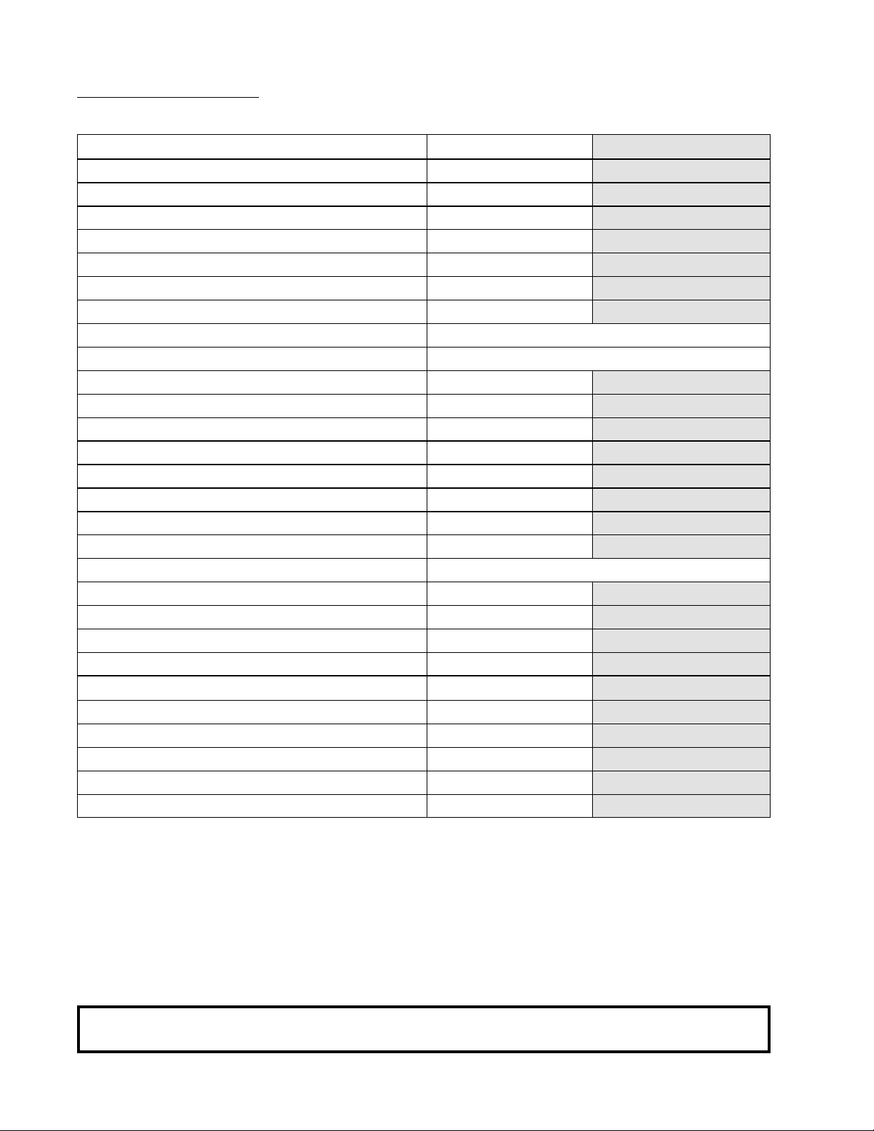
Important
For your convenience, log the following information:
DATE OF PURCHASE MODEL NO.
DISTRIBUTORS NAME
Serial Number(s)
AD-464
Replacement parts can be obtained from your distributor or the ADC factory. When ordering replacement parts from the
factory, you can FAX your order to ADC at (508) 678-9447 or telephone your orders directly to the ADC Parts Department at
(508) 678-9000. Please specify the dryer model number and serial number in addition to the description and part number, so
that your order is processed accurately and promptly.
The illustrations on the following pages may not depict your particular dryer exactly. The illustrations are a composite of the
various dryer models. Be sure to check the descriptions of the parts thoroughly before ordering.
“IMPORTANT NOTE TO PURCHASER”
Information must be obtained from your local gas supplier on the instructions
to be followed if the user smells gas. These instructions must be posted in a
prominent location near the dryer.
Page 3
IMPORTANT
YOU MUST DISCONNECT and LOCKOUT THE ELECTRIC SUPPLY and THE GAS
SUPPLY or THE STEAM SUPPLY BEFORE ANY COVERS or GUARDS ARE
REMOVED FROM THE MACHINE TO ALLOW ACCESS FOR CLEANING, ADJUSTING, INSTALLATION, or TESTING OF ANY EQUIPMENT per OSHA (Occupational
Safety and Health Administration) STANDARDS.
«Attention: Lor des opérations d’entretien
“Caution: Label all wires prior to
disconnection when servicing controls. Wiring
errors can cause improper operation.”
des commandes étiqueter tous fils avant
de les déconnecter. Toute erreur de
câblage peut étre une source de danger et
de panne.»
CAUTION
DRYERS SHOULD NEVER BE LEFT UNATTENDED WHILE IN OPERATION.
WARNING
CHILDREN SHOULD NOT BE ALLOWED TO PLAY ON OR NEAR THE DRYER(S).
CHILDREN SHOULD BE SUPERVISED IF NEAR DRYERS IN OPERATION.
FOR YOUR SAFETY
DO NOT DRY MOP HEADS IN THE DRYER.
DO NOT USE DRYER IN THE PRESENCE OF DRY CLEANING FUMES.
WARNING
UNDER NO CIRCUMSTANCES should the door switch or the heat circuit devices
ever be disabled.
Page 4
WARNING
The dryer must never be operated with any of the back guards, outer tops, or service
panels removed. PERSONAL INJURY or FIRE COULD RESULT.
WARNING
DRYER MUST NEVER BE OPERATED WITHOUT THE LINT FILTER/SCREEN IN
PLACE, EVEN IF AN EXTERNAL LINT COLLECTION SYSTEM IS USED.
IMPORTANT
PLEASE OBSERVE ALL SAFETY PRECAUTIONS displayed on the equipment and/or
specified in the installation and operator's manual included with the dryer.
Dryers must not be installed or stored in an area where it will be exposed to water or weather.
The wiring diagram for the dryer is located in the front electrical control box area.
Page 5

Table of Contents
SECTION I
SAFETY PRECAUTIONS .................................................................................................................. 3
SECTION II
ROUTINE MAINTENANCE .............................................................................................................5
A. Cleaning ..................................................................................................................................... 5
B. Lubrication .................................................................................................................................. 7
C. Adjustments ................................................................................................................................ 8
SECTION III
SPECIFICATIONS .............................................................................................................................. 9
A. Gas Models (ADG-464) ............................................................................................................. 9
B. Steam Models (ADS-464) ........................................................................................................ 10
C. Electrical Service Specifications ................................................................................................. 11
SECTION IV
INSTALLATION REQUIREMENTS ............................................................................................. 12
A. Enclosure/Air Supply/Exhaust Requirements .............................................................................. 12
B. Electrical and Gas Requirements ................................................................................................ 13
SECTION V
COMPONENT DESCRIPTION/REPLACEMENT ....................................................................... 14
A. Tumbler Support and Drive System ........................................................................................... 14
B. Main Air Blower/Heat Reclaimer System ................................................................................... 16
C. Compressed Air System ........................................................................................................... 18
D. Safety Devices .......................................................................................................................... 22
E. Blower (Squirrel Cage Fan) Motor Assembly ............................................................................ 24
F. Blower (Squirrel Cage Fan) Electrical Components .................................................................... 29
G. Tumbler (Basket) System ........................................................................................................... 31
H. Rotational Sensor Assembly ....................................................................................................... 39
I. Top Of Tumbler (Basket) Temperature Door Assembly ............................................................. 41
J. Tumbler (Basket) Electrical Components .................................................................................... 42
SECTION VI
PLC (PROGRAMMABLE LOGIC CONTROLLER) SYSTEM .................................................. 44
A. PLC (Programmable Logic Controller) Description .................................................................... 44
B. PLC (Programmable Logic Controller) Component Replacement ............................................... 48
SECTION VII
BASE SECTION ............................................................................................................................... 76
A. Lint Drawer/Lint Chamber Switches .......................................................................................... 76
B. Resistive Temperature Device .................................................................................................... 79
Page 6

SECTION VIII
SPRINKLER SYSTEM .................................................................................................................... 81
A. Sprinkler System Description .................................................................................................... 81
SECTION IX
AIR JET SYSTEM ............................................................................................................................ 85
A. Air Jet System .......................................................................................................................... 85
SECTION X
STACK VALVE ASSEMBLY ........................................................................................................... 86
A. Pneumatic Valve ........................................................................................................................ 86
SECTION XI
PENDANT ASSEMBLY ................................................................................................................... 91
A. Pendant Assembly Description .................................................................................................. 91
Page 7
SECTION I
SAFETY PRECAUTIONS
CAUTION: The dryer should never be left unattended while in operation.
WARNING: For your safety, the information in this manual must be followed to minimize the risk of
fire or explosion or to prevent property damage, personal injury, or loss of life.
WARNING: The dryer must never be operated with any of the back guards, outer tops, or
service panels removed. PERSONAL INJURY or FIRE COULD RESULT.
1. DO NOT store or use gasoline or other flammable vapors and liquids in the vicinity of this or any other
appliance.
2. Purchaser/user should consult the local gas supplier for proper instructions to be followed in the event the
user smells gas. The instructions should be posted in a prominent location.
3. WHAT TO DO IF YOU SMELL GAS...
a. DO NOT try to light any appliance.
b. DO NOT touch any electrical switch.
c. DO NOT use any phone in your building.
d. Clear the room, building, or area of
e. IMMEDIATELY call your gas supplier from a neighbor's phone. Follow the gas supplier's instructions.
f. If you cannot reach your gas supplier, call the fire department.
4. Installation and service must be performed by a qualified installer, service agency, or gas supplier.
5. Dryer(s) must be exhausted to the outdoors.
6. Although ADC produces a very versatile machine, there are some articles that, due to fabric composition or
cleaning method, should not be dried in it.
WARNING: Dry only water-washed fabrics. DO NOT dry articles spotted or washed in dry cleaning
solvents, a combustible detergent, or "all purpose" cleaner.
EXPLOSION COULD RESULT.
ALL occupants.
WARNING: DO NOT dry rags or articles coated or contaminated with gasoline, kerosene, oil, paint,
or wax.
EXPLOSION COULD RESULT.
3
Page 8
WARNING: DO NOT dry mop heads. Contamination by wax or flammable solvent will create a fire
hazard.
WARNING: DO NOT use heat for drying articles that contain plastic, foam, sponge rubber, or
similarly textured rubberlike materials. Drying in a heated basket (tumbler) may damage
plastics or rubber and also may be a fire hazard.
7. A program should be established for the inspection and cleaning of lint in the burner area, exhaust duct
work, and area around the back of the dryer. The frequency of inspection and cleaning can best be
determined from experience at each location.
WARNING: The collection of lint in the burner area and exhaust duct work can create a potential fire
hazard.
8. For personal safety, the dryer must be electrically grounded in accordance with local codes and/or the
NATIONAL ELECTRIC CODE ANSI/NFPA NO. 70-LATEST EDITION.
NOTE: Failure to do so will VOID THE WARRANTY.
9. UNDER NO CIRCUMSTANCES should the dryer door switches, lint drawer switch, or heat safety
circuit, ever be disabled.
WARNING: PERSONAL INJURY or FIRE COULD RESULT.
10. This dryer is not to be used in the presence of dry cleaning solvents or fumes.
11. Remove articles from the dryer as soon as the drying cycle has been completed.
WARNING: Articles left in the dryer after the drying and cooling cycles have been complete can
create a fire hazard.
12. READ and FOLLOW ALL CAUTION and DIRECTION LABELS ATTACHED TO THE DRYER.
IMPORTANT: Label ALL wires prior to disconnection when servicing the microprocessor controller
(computer) and the ignition module. WIRING ERRORS CAN CAUSE
IMPROPER and DANGEROUS OPERATION.
IMPORTANT: YOU MUST DISCONNECT and LOCKOUT THE ELECTRIC SUPPLY and
THE GAS SUPPLY or THE STEAM SUPPLY BEFORE ANY COVERS or
GUARDS ARE REMOVED FROM THE MACHINE TO ALLOW ACCESS
FOR CLEANING, ADJUSTING, INSTALLATION, or TESTING OF ANY
EQUIPMENT per OSHA (Occupational Safety and Health Administration)
STANDARDS.
4
Page 9
SECTION II
ROUTINE MAINTENANCE
A. CLEANING
A schedule should be established for periodic inspection, cleaning, and removal of lint from various areas of the
dryer, as well as throughout the duct work system. The frequency of cleaning can best be determined from
experience at each location. Maximum operating efficiency is dependent upon proper air circulation. The
accumulation of lint can restrict this air flow. If the guidelines in this section are met, an ADC dryer will provide
many years of efficient, trouble-free, and - most importantly - safe operation.
WARNING: LINT FROM MOST FABRICS IS HIGHLY COMBUSTIBLE. THE
ACCUMULATION OF LINT CAN CREATE A POTENTIAL FIRE HAZARD.
WARNING: KEEP DRYER AREA CLEAR AND FREE FROM COMBUSTIBLE
MATERIALS, GASOLINE, and OTHER FLAMMABLE VAPORS and
LIQUIDS.
NOTE: REMOVE POWER FROM THE MACHINE BEFORE PERFORMING ANY
MAINTENANCE IN THE DRYER.
NOTE: Suggested time intervals shown are for average usage which is considered six (6) to eight (8)
operational (running) hours per day.
SUGGESTED CLEANING SCHEDULE
EVERY THIRD or FOURTH LOAD
Clean the lint screen. A clogged lint screen will cause poor dryer performance. The lint screen is located in
the lint drawer in the base of the dryer. Pull out the lint drawer, brush the lint off the lint screen, and remove
the lint. Inspect the lint screen and replace if torn.
NOTE: The frequency of cleaning the lint screens can best be determined from experience at each
location.
WEEKLY
Open the hinged panels on each side of the tumbler section and remove any lint accumulation from the tumbler
drive motor, drive shafts, gear reducer, drive belts, drive wheels, and drive shaft bearings.
Slide the lint basket all the way out of the dryer and clean any lint accumulation off of the temperature sensor
bracket, which is located above the lint basket.
WARNING: TO AVOID THE HAZARD OF ELECTRICAL SHOCK, DISCONTINUE
ELECTRICAL SUPPLY TO THE DRYER.
5
Page 10

MONTHLY
Empty the compressed air filter bowl.
Clean any lint accumulation from the gas valve and burner area at the top of the dryer, the fan (impellor/
blower) motor, and the fan (impellor) bearings located in the dryer base.
EVERY 6 MONTHS
STEAM MODELS - clean the steam coil fins. We suggest using compressed air and a vacuum cleaner with
brush attachment.
NOTE: When cleaning steam coil fins, be careful not to bend the fins. If fins are bent, straighten
by using a fin comb, which is available from any local air conditioning supply house.
Inspect and remove any lint accumulation in customer furnished exhaust duct work system and from the
dryers internal exhaust ducting.
NOTE: THE ACCUMULATION OF LINT IN THE EXHAUST DUCT WORK CAN
CREATE A POTENTIAL FIRE HAZARD.
NOTE: DO NOT OBSTRUCT THE FLOW OF COMBUSTION and VENTILATION AIR.
CHECK CUSTOMER FURNISHED BACK DRAFT DAMPERS IN THE EXHAUST
DUCT WORK. INSPECT and REMOVE ANY LINT ACCUMULATION WHICH
CAN CAUSE THE DAMPER TO BIND or STICK.
NOTE: When cleaning the dryer cabinet(s), avoid using harsh abrasives. A product intended for the
cleaning of appliances is recommended.
Clean off any lint accumulation on top of the temperature probe and the hi-limit switch located above the lint
basket.
6
Page 11
B. LUBRICATION
MONTHLY
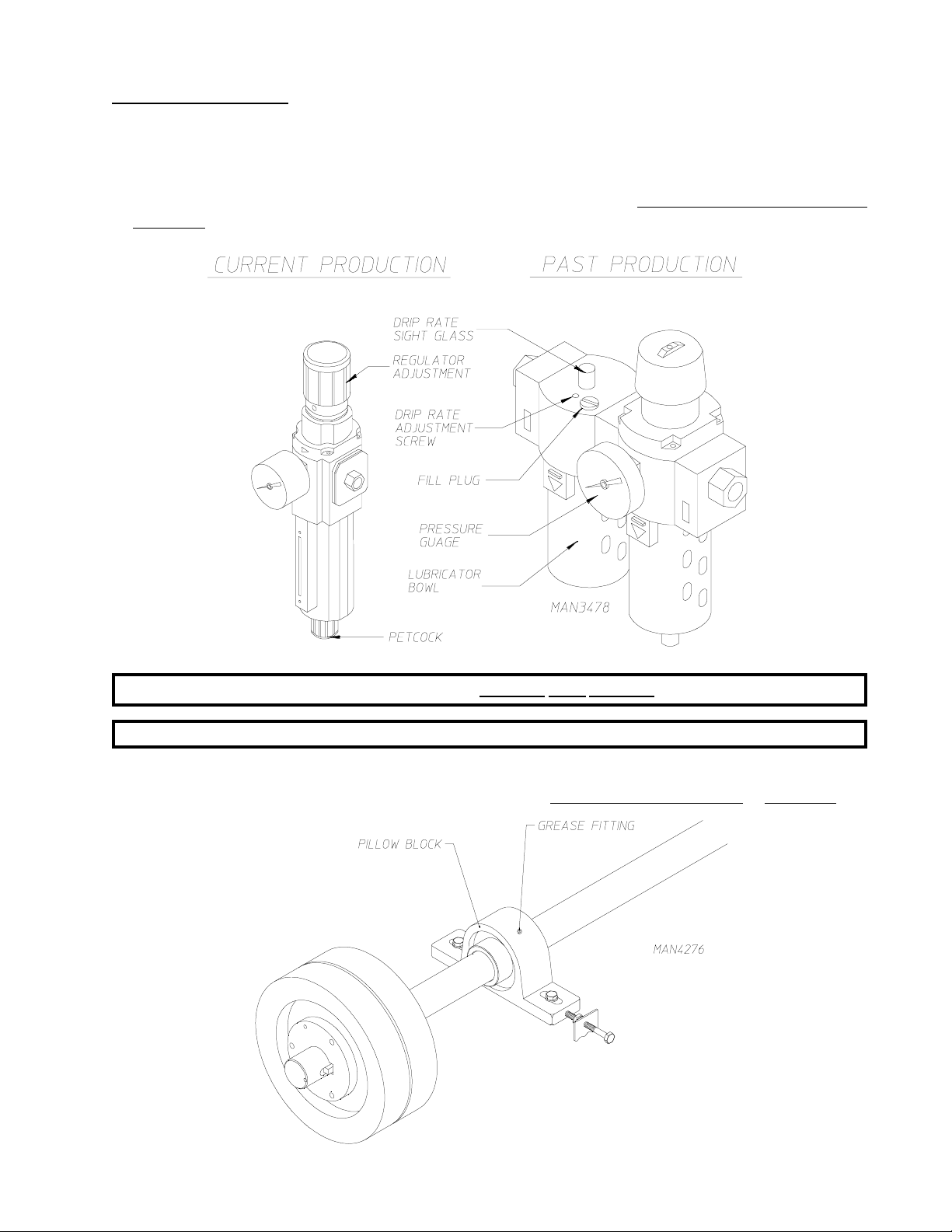
Check compressed air filter bowl for water. Empty by pressing the rubber petcock to the side. Additionally,
check lubricator bowl for oil. If empty, remove the fill plug and add oil. (
misting oil.) Replace the fill plug.
Use petroleum based 10/150 SSU
NOTE: LUBRICATOR SHOULD BE SET AT 1 DROP PER CYCLE.
NOTE: REGULATOR PRESSURE IS TO BE SET AT 80 PSI.
Apply high temperature grease to the four (4) 2" diameter tumbler drive shaft pillow block bearings and the
two (2) 1-3/4" diameter blower shaft pillow block bearings. (Use Shell Alvania #3 grease or equivalent.)
7
Page 12
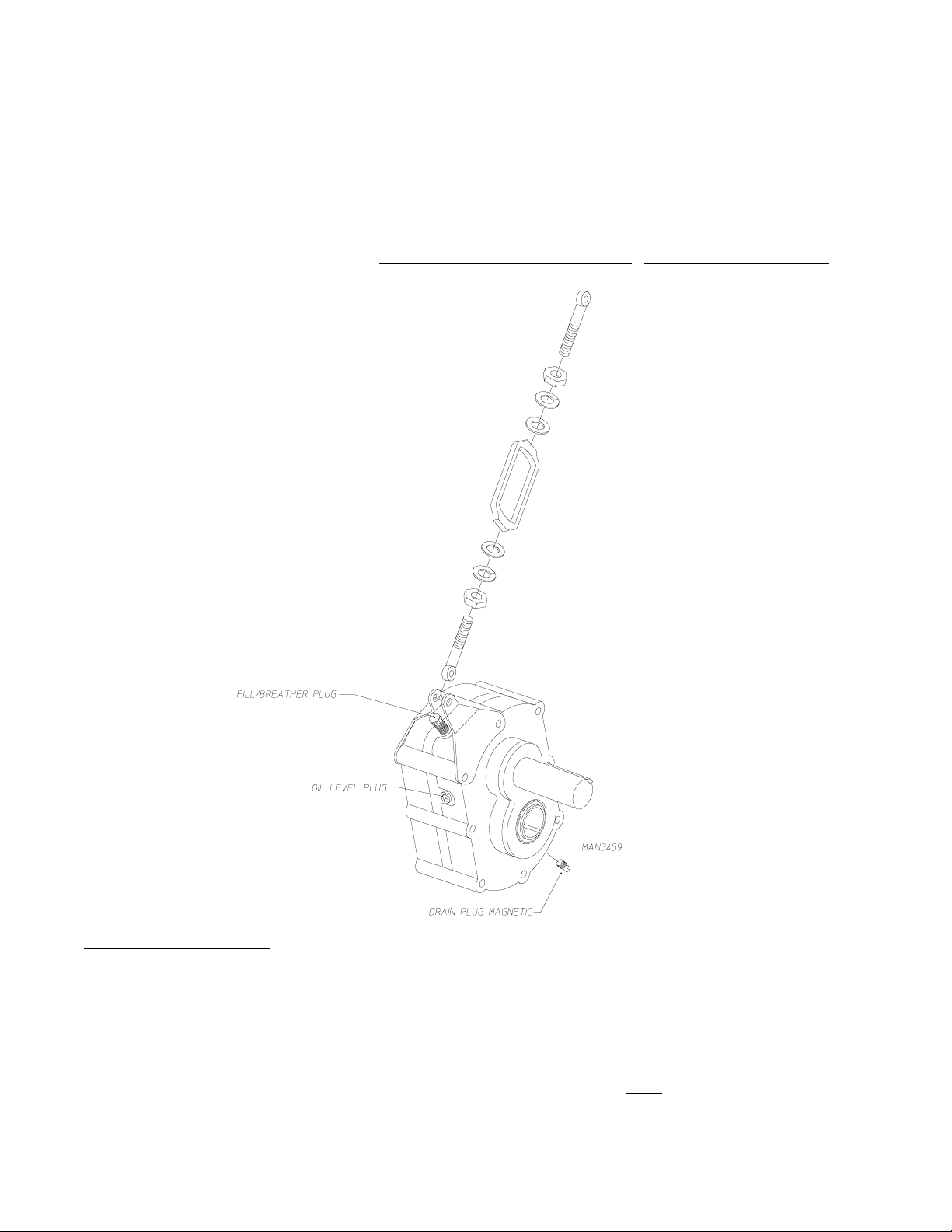
EVERY 6 MONTHS
Change gear oil in the tumbler shaft gear reducer.
1. Remove the drain plug (located at the bottom rear of the reducer).
2. After oil is completely drained replace the drain plug.
3. Remove the vent plug and pour in
SAE 90, or equivalent.
1.4 liters of Mobil Oil DTE HH5G (I.S.O. viscosity grade 460),
C. ADJUSTMENTS
7 DAYS AFTER INSTALLATION and EVERY 6 MONTHS THEREAFTER
Inspect bolts, nuts, screws, (bearing set screws), nonpermanent gas connections (i.e., unions, shut-off
valves, orifices), and grounding connections. Fan (impellor) V-belts, along with the motor and drive belts
should be examined and replaced if necessary. Tighten loose V-belts when necessary. Complete
operational check of controls and valves. Complete operational check of ALL safety devices (i.e., door
switches, lint drawer switch, sail switch, burner and hi-limit thermostats).
8
Page 13

SECTION III
A. GAS MODELS (ADG-464)
SPECIFICATIONS
MAXIMUM CAPACITY (D
TOTAL WEIGHT 9,695 lbs.
TOTAL SHIPPING WEIGHT 9,850 lbs.
TILT HEI GHT 137-1/4"
OPERATING HEIGHT 114-1/2"
FULL TILT DEPTH 117-1/2"
OPERATING DEPTH 95"
WIDTH 122"
TILT LOAD (
TILT UNLOAD
UNLOADING HEIGHT FROM FLOOR 43-3/4"
LOADING HEIGHT FROM FLOOR 65-5/8"
DOOR OPENING 53-1/4" x 49"
BASKET DIAMETER 69-1/8"
BASKET DEPTH 80-5/16"
BASKET VO LUME 175 cu. ft.
MINIMUM LOAD SIZE 250 lbs.
MAXIMUM LOAD SIZE 460 lbs.
BURNER TYPE On/Off
HEAT INPUT* 2,800,000 btu/hr.
BLOWER MOTOR 25 HP
BASKET MOTORS (2
BURNER BLOWER MOTOR 1-1/2 HP
BLOWER MAXIMUM A IRFLOW 13,000 cfm
MAXIMUM DUCT BACK PRESSURE 1.25" (W.C.)
MINIMUM DUCT DIAMEMTER 24"
COMPRESSED AIR PRESSURE REQUIRED 80 psi (±10 psi)
COMPRESSED AIR VOLUME REQUIRED 20 cf/hr
COMPRESSED C ONNECTION 3/8" N.P.T.
Shaded areas are stated in metric equivalents
REAR TI LT
(FRONT TILT
RY WEIGHT
)15º
)15º
MOTORS
) (2) 5 HP
)460 lbs.
209.09 kg
4,397.65 kg
4,467.96 kg
348.6 cm
290.83 cm
298.45 cm
241.3 cm
309.88 cm
111.12 cm
166.69 cm
135.26 cm x 124.46 cm
175.58 cm
203.99 cm
4.96 cu. m
113.64 kg
209.09 kg
On/Off
705,290 kcal/hr
18.65 kw
(2) 3.73 kw
1.12 kw
368 cmm
3.1 mbar
60.96 cm
5.51 bar (±.7)
.57 cm/hr
-
* Gas pressure into the dryer cannot exceed 13" W.C. (water column). If the gas supply pressure is
higher than 13" W.C., an external regulator must be installed.
NOTE: ADC reserves the right to make changes in specifications at any time, without notice or
obligation.
9
Page 14
B. STEAM MODELS (ADS-464)
MAXIMUM CAPACITY (D
RY WEIGHT
) 460 lbs.
TOTAL WEIGHT 11,000 lbs.
TOTAL SHIPPING WEIGHT (
STRETCH WRAP/SKID
) 11,162 lbs.
TILT HEIGHT 137-1/4"
OPERATING HEIGHT 114-1/2"
FULL TILT DEPTH 117-1/2"
OPERATING DEPTH 95"
WIDTH 122"
TILT LOAD (
TILT UNLOA D (
REAR TILT
FRONT TILT
) 15º
) 15º
UNLOA DING HEIGHT FROM FLOOR 43-3/4"
LOA DING HEIGHT FROM FLOOR 65-5/8"
DOOR OPENING 53-1/4" x 49"
135.26 cm x 124.46 cm
BASKET DIAMETER 69-1/8"
BASKET DEPTH 80-5/16"
BASKET VOLUME 175 cu. ft.
MINIMUM LOAD SIZE 250 lbs.
MAXIMUM LOAD SIZE 460lbs.
BOILER HORSEPOWER 60 Bhp
STEAM INLET CONNECTION SIZE* 2-1/2" N.P.T.
STEAM RETURN CONNECTION SIZE (2
BASKET MOTORS (2
MOTORS
)
BLOWER MOTOR
PLACES
)1 1/4" N.P.T.
(2)
5
HP
25
HP
BLOWER MAXIMUM AIRFLOW 13,000 cfm
MAXIMUM DUCT BACK PRESSURE
1.25" (
W. C.
)
MINIMUM DUCT DIAMEMTER 24"
COMPRESSED AIR PRESSURE REQUIRED 80 psi (±10 psi)
COMPRESSED AIR VOLUME REQUIRED 20 cf/hr
COMPRESSED AIR CONNECTION 3/8" N.P.T.
Shaded areas are stated in metric equivalents
209.09 kg
4,949.6 kg
5,063.08 kg
348.6 cm
290.83 cm
298.45 cm
241.3 cm
309.88 cm
111.12 cm
166.69 cm
175.58 cm
203.99 cm
4.96 cu. m
113.64 kg
209.09 kg
-
-
(2)
3.73 kw
18.65 kw
368 cmm
3.1 mbar
60.96 cm
5.63 bar (±.7)
.57 cm/hr
-
* Size of piping to dryer varies with installation conditions. Contact factory for assistance.
NOTE: ADC reserves the right to make changes in specifications at any time, without notice or
obligation.
10
Page 15
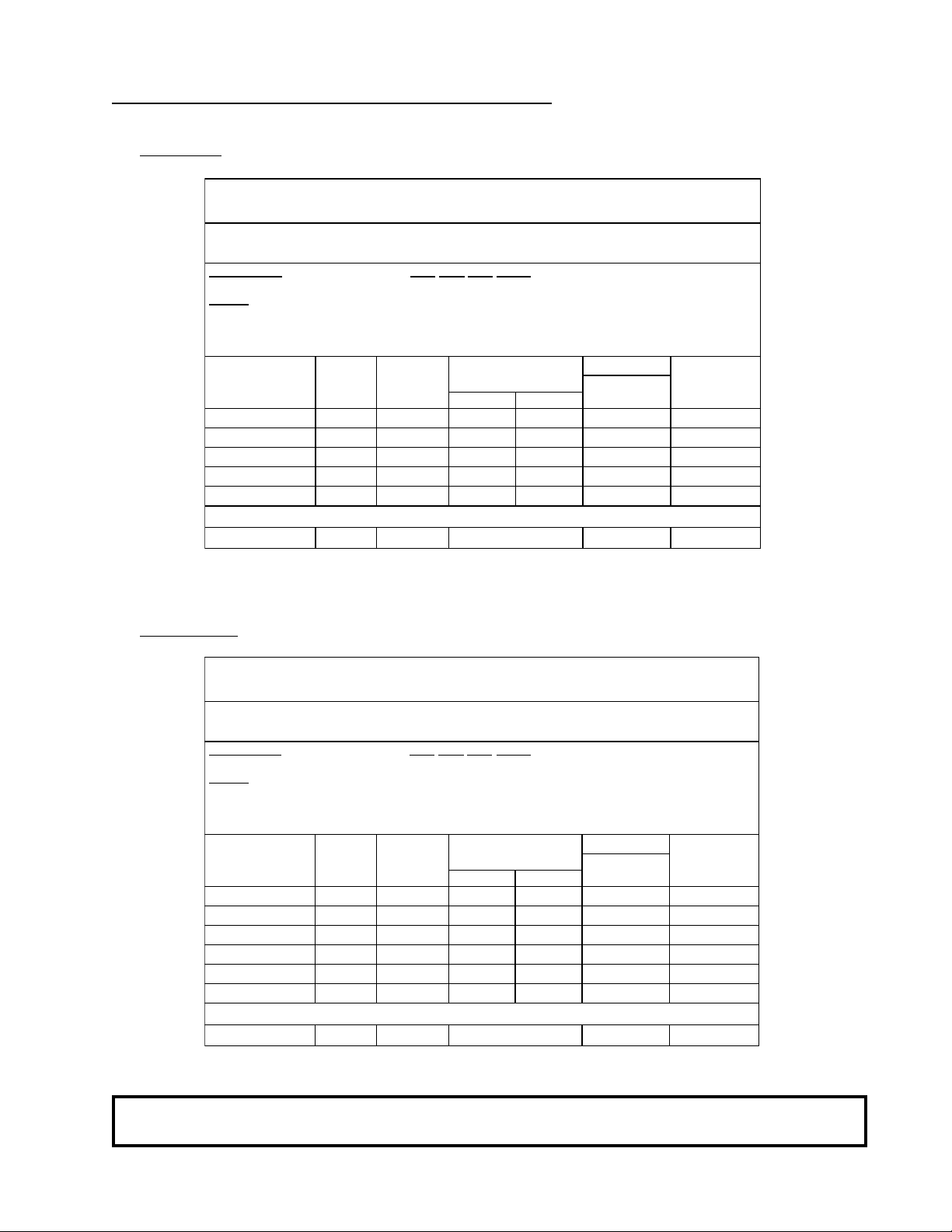
C. ELECTRICAL SERVICE SPECIFICATIONS
1. Gas Models
ADG-464 (GAS)
E
LECTRICAL SERVICE SPECIFICATIONS (PER DRYER
IMPORTANT: 2 08 VAC and 240 VAC ARE NOT THE SAME. When o rdering, specify exact voltage.
)*
NOTES
Dryer Nameplate
* Conta ct factory for information not listed.
** Minimum wire size is #16 AWG Stranded Type Wire...for individual len gths less than 100 feet.
2. Steam Models
IMPORTANT: 2 08 VAC a nd 240 VAC ARE NOT THE SAME. When ordering, specify exact voltage.
A. Fuse ratings are dual-element, time-delay, current limiting, class RK1 or RK5 ONLY.
:
B. Circuit b rea kers are the rmal magnet ic (i ndustrial) type ONLY. For othe rs, cal cu late/ve r if y
correct breaker size according to appliance amp draw rating and type of breaker used.
C. Circuit br eak ers for 3Ø dry ers must be 3-pole type.
SERVICE
VOLTAGE
208 3ø 3/4 107 --- 150 150
240 3ø 3/4 101 98 150 150
380-400 3ø 3/4 --- 53 80 90
416 3ø 3/4 --- 51 60 90
460/480 3ø 3/4 51 --- 60 90
PHAS E
1ø --- 2 3.5 5
WIRE
SERVICE
D
EDICATED SPRINKLER SERVICE
ADS-464 (S
E
LECTRICAL SERVICE SPECIFICATIONS (PER DRYER
APPROX.
AMP DR AW
60 Hz 50 Hz
TEAM
Dual Eleme nt
**
FUSIN G
Tim e D e la y
)
CIRCUIT
BREAKER
)*
NOTES
Dryer Nameplate
* Contact factory fo r information n ot listed.
** Minimum wire size is #16 AWG Stranded Type Wire...for indivi dual lengths less than 100 feet.
B. Circuit breakers are thermal magnetic (industrial) type ONLY. For othe rs, cal cul ate/ver ify
correct breaker size according to appliance amp draw rating and type of breaker used.
C. Circuit breakers for 3Ø dryers mu st be 3-pole type.
SERVICE
VOLTAGE
200 3ø 3 117 --- 150 150
208 3ø 3/4 102 --- 150 150
240 3ø 3/4 96 94 125 150
380-400 3ø 3/4 --- 51 60 90
416 3ø 3/4 --- 51 60 90
460/480 3ø 3/4 49 --- 60 90
PHASE
1ø --- 2 3.5 5
WIR E
SERVICE
D
EDICATED SPRINKLER SERVICE
APPROX.
AMP DRAW
60 Hz 50 Hz
Dual Element
**
FUSING
Time D e la y
BREAKER
CIRCUIT
A. Fuse ratings are dual-element, time-delay, current limiting, class RK1 or RK5 ONLY.
:
NOTE: ADC reserves the right to make changes in specifications at any time, without notice or
obligation.
11
Page 16
SECTION IV
INSTALLATION REQUIREMENTS
Installation should be performed by competent technicians in accordance with local and state codes. In the
absence of these codes, installation must conform to applicable AMERICAN NATIONAL STANDARDS:
National Fuel Gas Code ANSI Z223.1-LATEST EDITION
and/or
National Electric Code ANSI/NFPA No. 70-LATEST EDITION
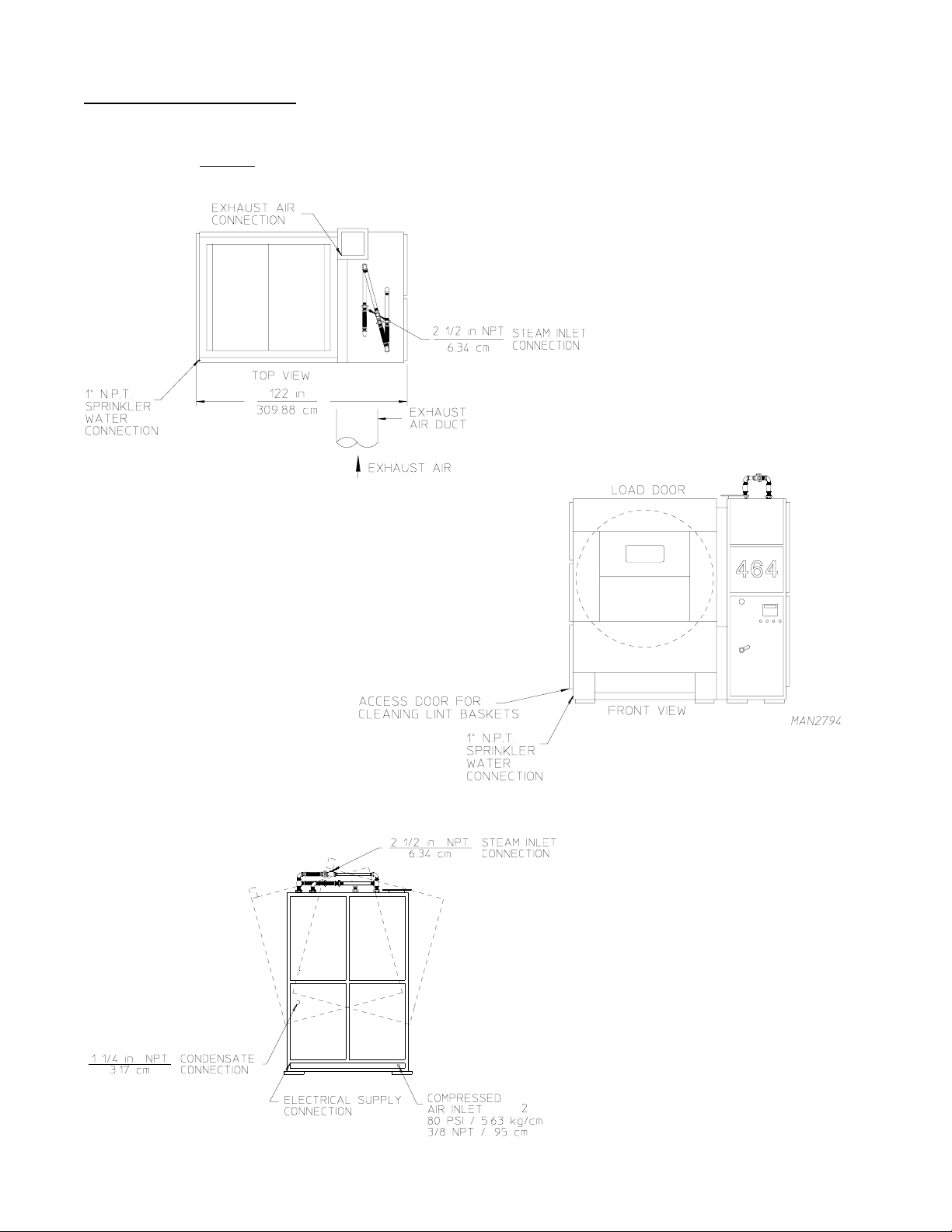
A. ENCLOSURE / AIR SUPPLY / EXHAUST REQUIREMENTS
NOTE: The following information is very brief and general. For detailed descriptions, refer to the
ADG-464 Installation/Operator's Manual (ADC Part No. 112193) for Gas Model dryers and
ADS-464 Installation/Operator's Manual (ADC Part No. 112103) for Steam Model dryers.
Bulkheads and partitions around the dryer should be made of noncombustible materials. Allowances
should be made for the opening and closing of the control door and lint door. Also, allowances should be
made in the rear for ease of maintenance. Refer to the
Part No. 112193) for Gas Model dryers and ADS-464 Installation/Operator's Manual (ADC Part No. 112103)
for Steam Model dryers for recommended distances and minimum allowances required.
ADG-464 Installation/Operator's Manual (ADC
When the dryer is operating, it draws in room air, heats it, passes this air through the basket (tumbler), and
exhausts it out of the building. Therefore, the room air must be continually replenished from the outdoors. If the
make-up air is inadequate, drying time and drying efficiency will be adversely affected. Ignition problems and
burner air switch "fluttering" problems on gas dryers may result, and you also could have premature motor failure
from overheating. The air supply must be given careful consideration to insure proper performance of each
dryer.
IMPORTANT: Make-up air must be provided from a source free of dry cleaning fumes. Make-up
air that is contaminated by dry cleaning fumes will result in irreparable damage to
motors and other dryer components.
Exhaust duct work should be designed and installed by a competent technician. Improperly sized duct work will
create excessive back pressure which will result in slow drying, increased use of energy, and shutdown of the
burner by the lint burner switch, over-burner hi-limit or exhaust limit. Refer to the ADG-464 Installation/Operator's
Manual (ADC Part No. 112193) for Gas Model dryers and ADS-464 Installation/Operator's Manual (ADC Part
No. 112103) for Steam Model dryers for more detail.
CAUTION: IMPROPERLY SIZED OR INSTALLED EXHAUST DUCT WORK CAN
CREATE A POTENTIAL FIRE HAZARD.
12
Page 17
B. ELECTRICAL REQUIREMENTS and GAS REQUIREMENTS
It is your responsibility to have ALL electrical connections made by a properly licensed and competent
electrician to assure that the electrical installation is adequate and conforms with local and state regulations or
codes. In the absence of such codes,
the applicable requirements of the National Electric Code ANSI/NFPA No. 70-LATEST EDITION.
IMPORTANT: Failure to comply with these codes or ordinances and/or the requirements stipulated in
this manual can result in personal injury or component failure.
The dryer installation must meet the AMERICAN NATIONAL STANDARD; National Fuel Gas Code ANSI
Z223.1-LATEST EDITION, as well as, local codes and ordinances, and must be done by a qualified technician.
NOTE: Undersized gas piping will result in ignition problems and slow drying and can create a safety
hazard.
The dryer must be connected to the type of gas (natural or L.P.) indicated on the dryer data label. If this
information does not agree with the type of gas available, contact the distributor who sold the dryer or contact the
factory.
ALL electrical connections, material, and workmanship must conform to
C. OPERATIONAL SERVICE CHECK PROCEDURE
After performing any service or maintenance function, an operational check should be performed to insure that
ALL components are performing properly.
1. Make a complete operational check of ALL the operating controls to insure that the timing is correct,
temperature selection switches are functioning properly.
2. Make a complete operational check of ALL safety related circuits, door switches, hi-limit thermostat, air
pressure switches, RTD (Resistive Temperature Device) probes, etc.
13
Page 18
SECTION V
COMPONENT DESCRIPTION/REPLACEMENT
A. TUMBLER SUPPORT and DRIVE SYSTEM
IMPORTANT: Always keep the tumbler (basket) section of the dryer in an upright position when
moving it.
1. Tumbler
The tumbler is made of five (5) 14 gauge stainless steel perforated panels, five (5) stainless steel lifting ribs,
and two (2) outer tumbler rings. The tumbler is a completely welded assembly so the perforated panels
not removable.
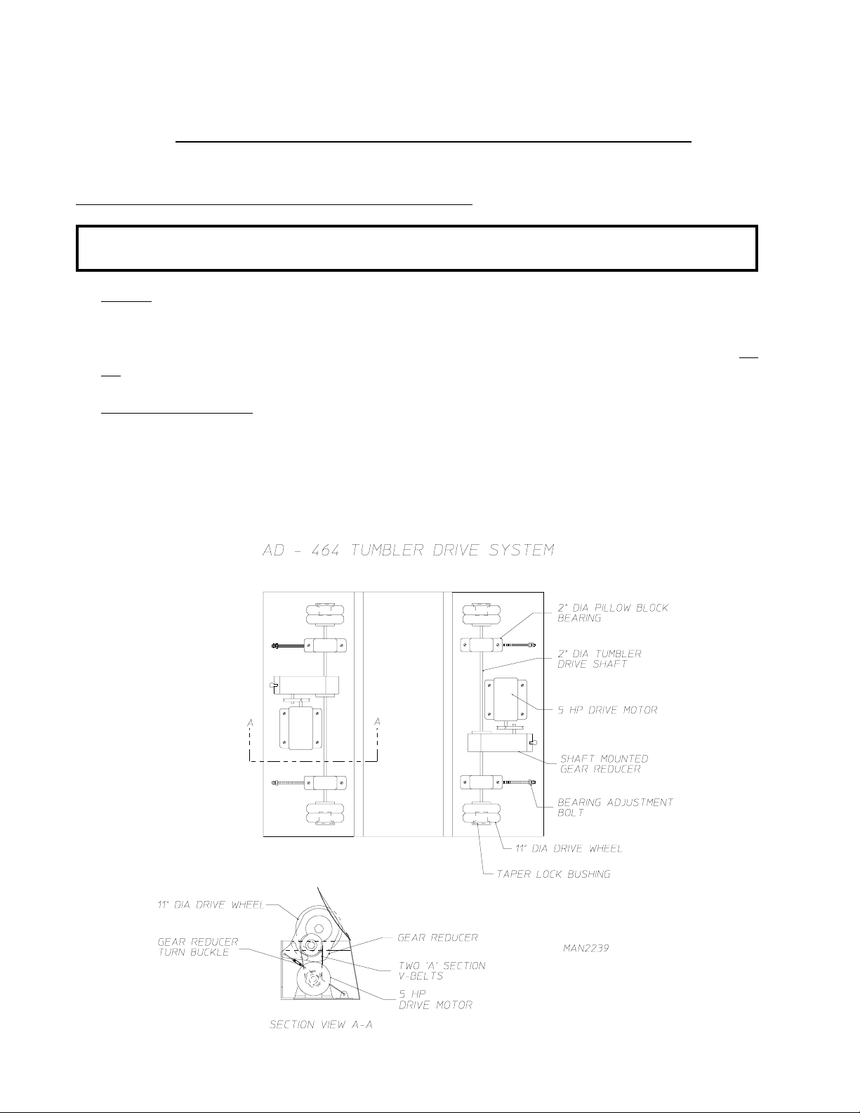
2. Tumbler Support System
The tumbler sits on four (4) 11-inch diameter heavy-duty rubber roller wheels which supports and drives the
tumbler. The rubber wheels are molded into each of four (4) steel hubs. The steel hubs are flattened to the
2-inch diameter drive shafts by taper lock bushings. Each drive shaft is supported by two (2) 2-inch diameter
heavy duty roller bearings. The position of the tumbler is adjusted by moving these bearings in or out with the
four (4) bearings adjustment bolts.
are
14
Page 19
3. Tumbler and Basket Drive System
There are two (2) 5 HP tumbler drive motors. Each motor drives one of the 2-inch diameter tumbler drive
shafts, and the motors spin simultaneously so that ALL four (4) sets drive wheels work together to spin the
tumbler.
Each motor is connected to the drive shaft by two (2) “A” section V-belts, driving a shaft-mounted (5.6 to
ratio) gear reducer. This produces a tumbler shaft speed of 200 RPM to 205 RPM and a tumbler speed of
31.5 RPM. Proper tension is maintained on the V-belts by tightening the gear reducer turnbuckle support.
The oil in each gear reducer must be replaced every six (6) months by 1.4 liters of I.S.O. viscosity Grade
460 gear oil.
Servicing the Drive System
4.
a. Removing a Drive Wheel
The drive wheels are removed through the front and back panels of the dryer, not through the sides. The
front loading door and back loading door panels are hinged at the top. Remove the bolts holding these
panels to tumbler section frame and swing the panel out. The two (2) 1/4-inch poly-flo tubes connected to
the load door piston have to be removed to allow the panel to swing up far enough out to get access to the
drive wheels. Likewise, the following electrical disconnections must be performed (refer to page 32).
15
Page 20
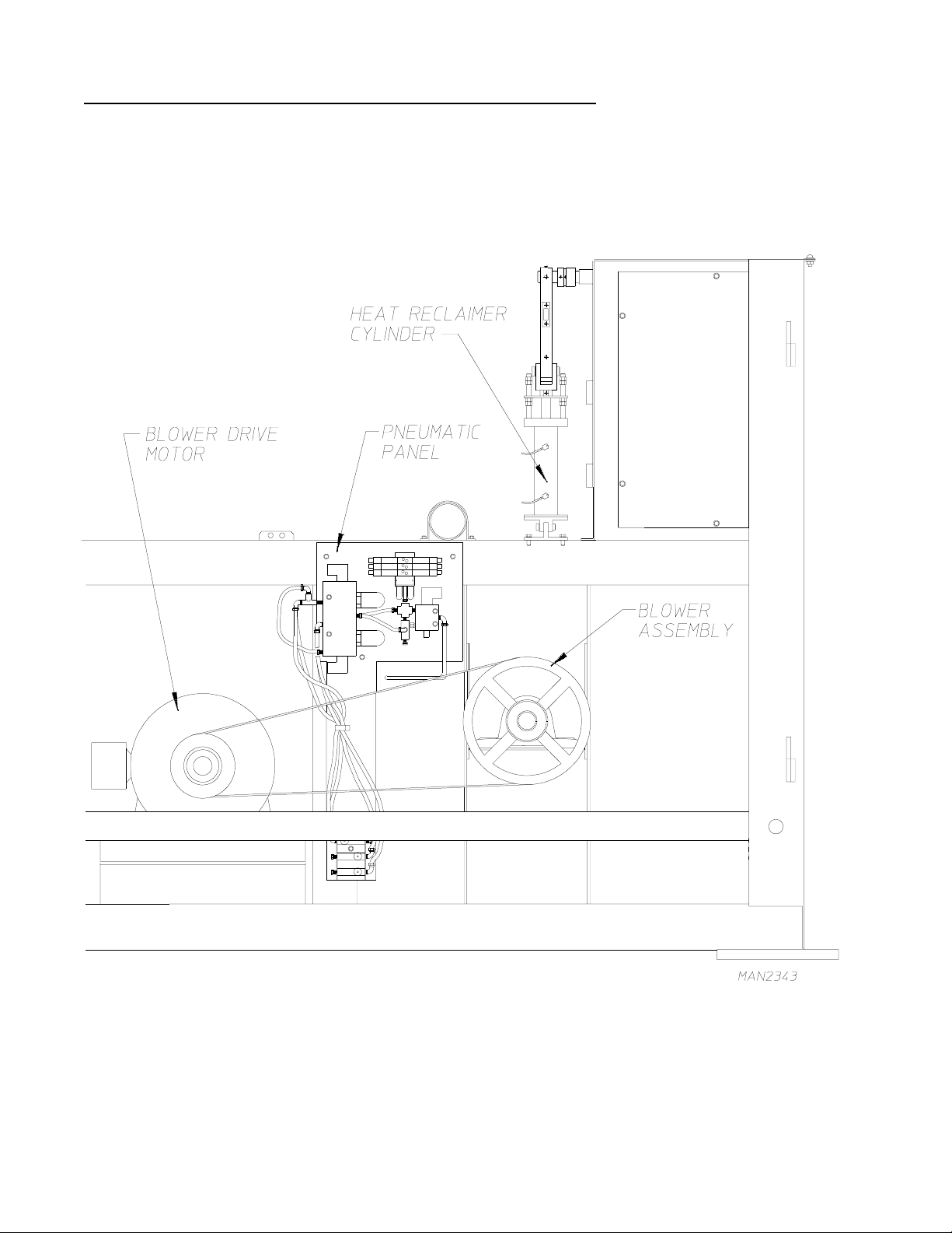
B. MAIN AIR BLOWER/HEAT RECLAIMER SYSTEM
The fan which moves the exhaust air through the dryer is a 22-inch diameter, squirrel cage fan that is driven at
1,100 rpm by a 25 HP motor. This fan moves a maximum of 13,000 cfm air through the dryer.
16
Page 21
The dryer is equipped with a pneumatically operated heat reclaimer damper, which when opened, will recirculate
approximately fifteen percent (15%) of the dryer’s exhaust air.
The heat reclaimer dampener is closed until ignition of flame has been established. Then, the damper piston is
actuated, opening the damper and recirculating fifteen percent (15%) of the exhaust air back over the gas burner
and into the tumbler. The damper remains open for the rest of the drying cycle. On cool down, the damper
closes, exhausting
ALL of the 13,000 cfm which ensures a fast cool down of the load.
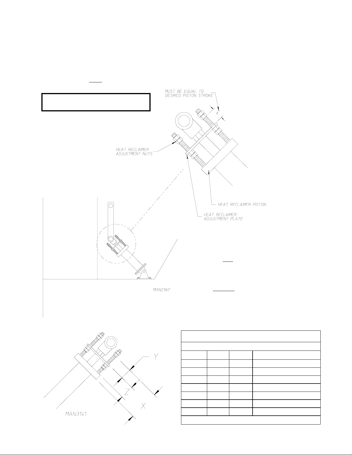
NOTE: Gas Dryers must have a "Y"
dimension of 1-3/16".
HEAT RECLAIMER ADJUSTMENT
1. REMOVE ELECTRICITY FROM THE UNIT.
2. LOOSEN HEAT RECLAIMER ADJUSTMENT NUTS
ON ALL FOUR (4) CORNERS OF THE HEAT
RECLAIMER PISTON.
3. ADJUST THE BOTTOM HEAT RECLAIMER NUTS
DOWN TO THEIR DESIRED POSITION WHICH
WILL GIVE THE PROPER PISTON STROKE.
EXAMPLE: IF THE DESIRED PISTON STROKE IS
4. TIGHTEN TOP HEAT RECLAIMER NUTS DOWN
ONTO THE BOTTOM HEAT RECLAIMER NUTS.
H
EAT RECLAIMER SETTINGS
Z = 1-5/8
Y+Z=X Y %HR Inches Rec lai med
1-1/8" 1/2" 7.46 1-1/4"
2-5/8" 1" 15.67 2-5/8"
3-1/8" 1-1/2" 25.37 4-1/4"
3-5/8" 2" 34.32 5-3/4"
4-1/8" 2-1/2" 43.28 7-1/4"
4-5/8" 3" 50.74 8-1/2"
5-1/8" 3-1/2" 58.95 9-7/8"
TWO (2) INCHES (5.1 CM), THAN THE
DISTANCE "X" IN THE ILLUSTRATION
MUST BE TWO (2) INCHES (5.1 CM).
FULL OP EN 16- 3/4"
17
Page 22
C. COMPRESSED AIR SYSTEM
The compressed air system of the dryer consists of a number of pneumatic pistons located throughout the dryer,
an FRL (Filter/Regulator/Lubricator) assembly, and pneumatic control panel.
1.
Air Pistons
The pistons are actuated by solenoid and flow control valves that are under computer control. The pneumatic
pistons are used to:
• Tilt the dryer for loading and unloading.
• Open and close load and unload doors
• Operate heat reclaimer.
• Operate the cool down damper and the intake air damper.
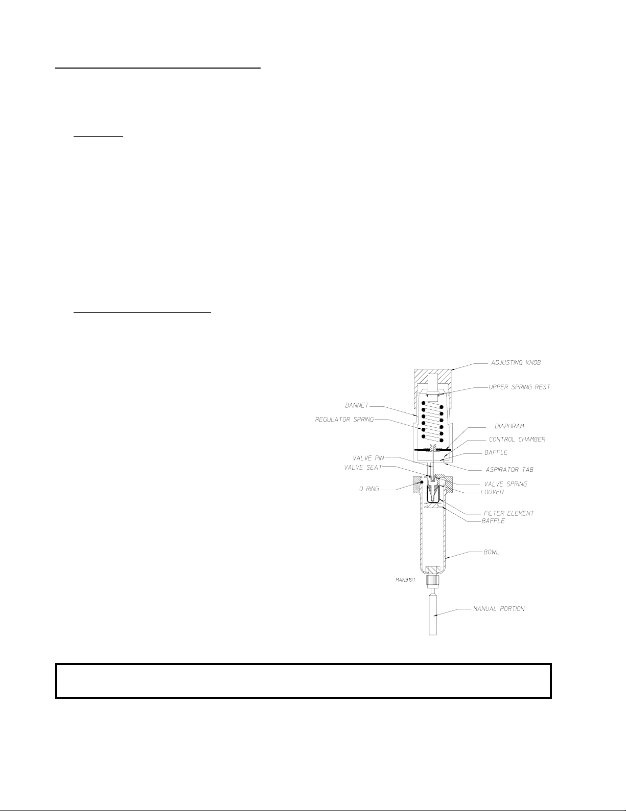
2. Filter and Regulator Assembly
The purpose of the filter is to remove bulk liquids and solid particles from the compressed air stream. The
filter element provides mechanical separation of solids. Centrifugal force inside the filter bowl separates bulk
liquids and larger solid particles.
The filter consists of a louver which causes a
centrifugal spinning action to separate contaminants.
A filter which mechanically separates contaminants
is also present. The filter bowl collects the
contaminants and a baffle prevents turbulence from
picking up contaminants at the bottom of the bowl
and returning them to the air stream.
a. Filter Maintenance
1) To remove filter element ...
Twist the filter bowl 1/8 turn clockwise (CW). Then pull
the bowl down to expose the filter element. To remove
the filter element, unscrew the baffle (this will allow
element removal).
2) To clean filter element ...
The filter element can be cleaned with soap and water.
FILTER / REGULATOR
NOTE: When replacing the filter element bowl care must be taken to ensure that the O-ring does not
get pinched.
18
Page 23
b. Regulator Operation
The adjustment knob simply acts upon a spring rest located on the spring and directly compresses the
spring as it is adjusted. A non-rising low torque adjustment screw is used on this type of filter and regulator.
The upper spring rest is located on top of the regulator spring and transmits force from the adjustment
screw to the spring. Regulators use simple wire coil springs for controlling the downstream regulator
pressure. The bonnet houses the adjustment spring and is used to help retain the diaphragm. The diaphragm
moves up when the downstream pressure reaches its preset pressure level, which in turn closes the valve.
A self-relieving regulator is designed to automatically relieve overpressure in the secondary side of the
regulator.
NOTE: THIS SELF-RELIEVING FEATURE IS NOT DESIGNED TO BLEED THE DOWN-
STREAM PRESSURE
Dryer must be provided with a clean, dry, regulated 80 PSI (+/- 10 PSI) air supply (equivalent
volume - 20 cf/hr).
The regulator should be set at 80 PSI (+/- 10 PSI). To set pressure, pull the adjusting knob up and either
turn the knob clockwise (CW) to increase the pressure or counterclockwise (CCW) to decrease the
pressure.
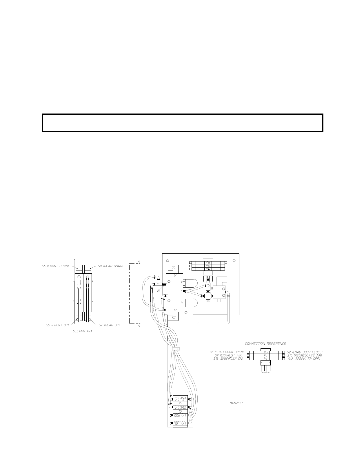
3.
Pneumatic Control Panel
.
The pneumatic control panel of a 2-way tilt dryer has two (2) tilting solenoid valves, one to control the front
set of tilting pistons and a second to control the rear set of tilting pistons. A 1-way tilt dryer has only one (1)
tilting solenoid valve.
Each valve has five (5) 1/2-inch F.P.T. ports and two (2) electric solenoids, one on each side of the valve.
19
Page 24

To tilt the dryer back, a 120 volt signal is applied to the front pistons solenoid connector #S5, and no voltage
is applied to the solenoid connector #S8. The internal spool in the valve will move and 80 PSI of air will enter
the bottom port of the front tilting pistons, extending the front tilting piston rods and tilting the dryer back for
loading. The top piston ports are bled to the atmosphere. To level the dryer after loading, the voltage signals
are reversed. No voltage is applied to the “S5” solenoid, and 120 volts are applied to the “S8” solenoid. The
valve spool will now move so that 80 PSI of air is applied at the top piston ports, while the bottom piston ports
are bled to the atmosphere. The piston rods will now retract, leveling the dryer. On a 2-way tilt dryer, the
rear tilting piston solenoid valve acts in the same manner.
The tilting piston valves are three (3) position valves. This means that, if no voltage is applied to both positions
(“S5” and “S8”) ALL five (5) valve ports are blocked. If the dryer is tilting or leveling and power to the dryer
is shut off, the pistons will lock in position, holding the dryer in a partially tilted position.
The dryer can be made to tilt faster or slower by adjusting the pistons 3/8-inch flow control valves which are
located on the pneumatic control panel.
4.
Internal and External Pilot Air Supply
On 2-way tilt dryers, a pneumatic safety circuit is incorporated to prevent both front and rear tilting pistons
from extending their rods at the same time. When 120 volts is supplied to the “S5” side of the front tilting
piston solenoid valve coil, the round internal spool in the core of the solenoid will move, allowing 80 PSI air to
flow into the bottom ports of the front tilting pistons, while the top ports of these pistons are bled to the
atmosphere. In addition to this 120 volt electrical signal, the spool also requires a 30 PSI supply of
compressed air to change its position. This pilot air can either be supplied internally, tapped off the 80 PSI air
supply connected to port no. 1 through holes in the body of the solenoid valve or it can be supplied externally
through the 1/8-inch F.P.T. connection located on either end of the solenoid valve. If no pilot air is supplied to
the solenoid valve then the spool cannot move, even with voltage supplied to the solenoid valve coil.
This can be used to prevent both sets of tilting pistons from extending their rods at the same time. When the
front tilting piston rods are extended, 80 PSI air is connected to the bottom piston ports, while the top piston
ports are bled to the atmosphere. So, by tapping the external pilot air supply to the rear tilting rods are
extended, then there is no pilot pressure available to the rear tilting piston solenoid valve so that its spool
cannot move and the rear tilting piston rods cannot extend if a 120 volt signal is sent to its “12” side solenoid
valve coil.
The external pilot air supply to the front tilting piston is tapped off the rear tilting piston top port air line so that
whenever the rear piston rods are extended, there is no pilot air supplied to the front tilting piston solenoid
valve and the front tilting piston rods cannot extend. On the solenoid valve supplied on the dryer, the #12 side
valve is externally piloted, while #14 side valve is internally piloted.
A valve can easily be checked for internal or external piloting by removing the two (2) screws which hold the
solenoid operator onto the valve. For an internal pilot air to be supplied to the valve spool. For an external
pilot, the solid sealing disc must be positioned on top of the internal port.
5. Loading Doors and Heat Reclaimer, Cool Down and Intake Air Damper
These solenoid valves are located in the 4-station manifold block on the pneumatic control panel. The front
load door piston, rear unload door piston (optional), and the sprinkler water valve are ALL controlled by their
own 3-way double acting solenoid valve.
The three (3) pistons that control the heat reclaimer damper, cool down damper, and intake air damper are
controlled by a single 3-way double acting solenoid valve.
20
Page 25

To open the front loading door, a 120 volt signal is applied to S1, the coil of the valve that supplies air to the
load door or the heat reclaimer’s bottom port. The valve will open, and 80 PSI of air is supplied to the bottom
port of the piston. The piston rod will extend, and the door will open. No voltage is applied to S2, the coil of
the valve that controls the air supply to the door pistons top port so that this line is bled to the atmosphere.
To close the front loading door or heat reclaimer damper, the voltage signals are reversed, and the loading
door will close.
21
Page 26
D. SAFETY DEVICES
The dryer is equipped with numerous safety devices to ensure that the dryer operates safely. The chart on the
following page (
tripping.
page 23) lists each device with its location, function, computer display message, and result of
22
Page 27

Safety Devices Locations/Functions/Messages
1.
S
AFETY DEVICES
L
OCATION
F
UNCTION
C
OMPUTER
D
ISPLAY MESSAGE
R
ESULT OF
T
RIPP ING
Load Door Switch
Unload door switch (Two
door unit only)
Tilting Switches
Drum Rotation Sensor
Lint Chamber air pressure
switch
Burner Fan Air Flow
Switch
(Gas Dryers Only)
Hi/Lo Gas Pressure
Switch
(Gas Dryers Only)
Heat Reclaimer Damper
Switch
Heat Console Door
Access Door Switch
Exhaust Air Temp Control
Sensor
Left side of
Load door
Right side of
unload door
Top left side of
base module
Left side of
tumbler section
Rear of base
module
Center of heat
console
Lower left of
heat console
section
Right side of
heat console
Inside heat
console
Inside burner
section duct
Ensure s drye r load doors
are closed
Ensures dryer unl oad
doors are closed
"DOOR OPEN" Dryer will not run
"DOOR OPEN" D
Ensu res dryer is l evel " LEVE L FAULT" D
Ensures tumbler is
rotating
Ensures proper air fl ow
through dryer
"DRUM FAULT" S
"AI RFLOW FAULT" S
Ensures proper
combustion air flow into
"HE ATER FAULT" S
the burn er box
Ensures proper gas
supply pressure for
adequate ignition
Ensures that the heat
reclaime r is either
opened or closed
Ensures th at access doors
are closed
Moni tors tumbl er exhaust
air temp
"GAS SUPPLY
FA UL T"
Input L.E.D. #13 of
the PLC is off
"DOOR OPEN" D
"EXHAUST DSFL" S
RYER WILL NOT RUN
RYER WILL NOT RUN
TOPS HEAT ONLY
TOPS HEAT ONLY
TOPS HEAT ONLY
S
TOPS HEAT ONLY
N
ONE
RYER WILL NOT RUN
TOPS HEAT ONLY
Exhaust Air Hi Temp
Control Sensor
Intake Air Temp Control
Sensor (opt ional)
Intake Air Temp Control
Sensor
Burner Hi-Limit Safety
Sensor
Sprinkler Control Safety
Sensor
Lint Drawer Switches
Inside exhaust
duct
Top right of
tumbler section
Top right of
tumbler section
Top of burner
section
Top right of
tumbler section
Above lint
drawer handles
Moni tors tumbl er exhaust
and air temp
Moni tors tumbler air
intake temp
Moni tors tumbler air
intake temp
Monitors air temp above
the burn er box
Open sprinkler system
water valve on hi-temp
condi tion
Disables machine when
draw ers ar e open or if
drawers have not been
clea ned in last five load
"HI -TEMP FAULT" S
"INTAKE DSFL" S
"HI -TEMP FAULT" S
"HI -TEMP FAULT" S
Orange sprinkler
pilo t li ght comes on.
Alarm h orn sou nds.
Lint Drawer D
TOPS HEAT ONLY
TOPS HEAT ONLY
TOPS HEAT ONLY
TOPS HEAT ONLY
O
PENS THE SPINKLER
W
ATER VALVE
P
OWER DOWN THE
AND
W
HOLE DRYER
RYER WILL NOT RUN
23
Page 28
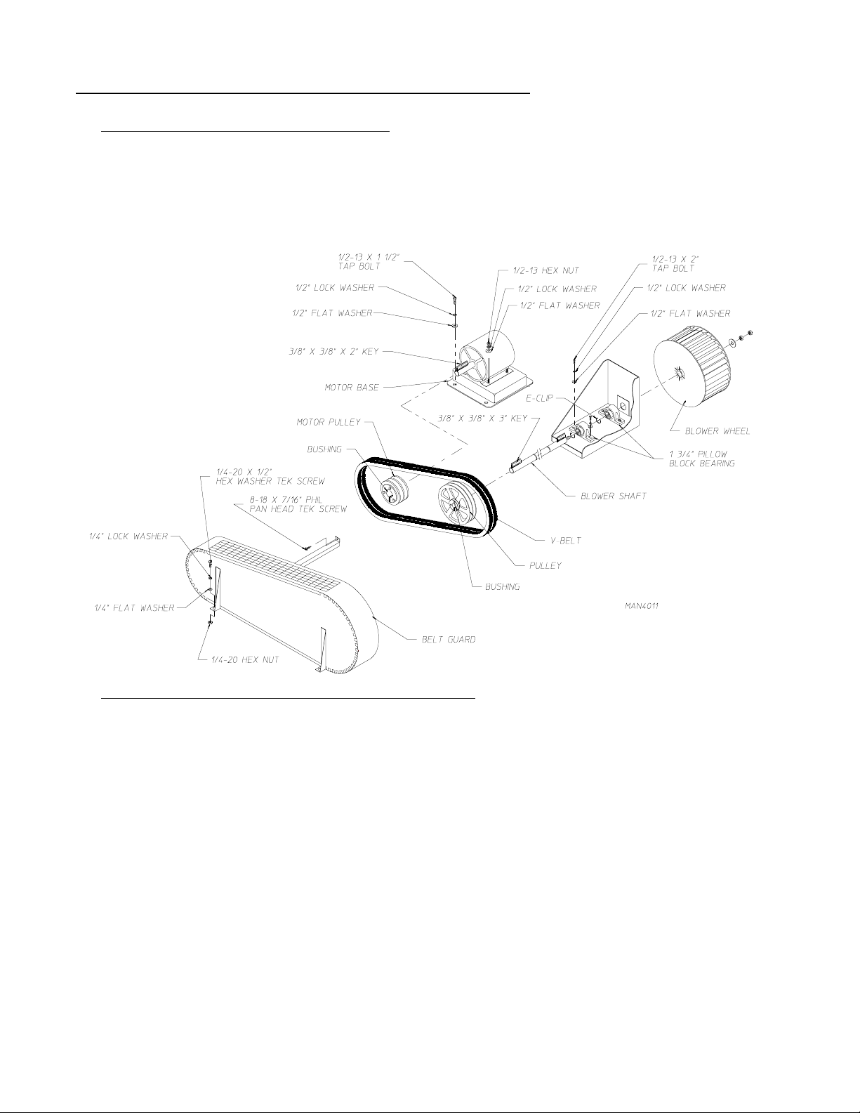
E. BLOWER (Squirrel Cage Fan) MOTOR ASSEMBLY
1. Blower (Squirrel Cage Fan) Motor Description
The dryer uses a 22-1/4 inch diameter blower (squirrel cage fan). It rotates (spins) in a counterclockwise
(CCW) direction, when viewed at the blower motor.
The blower shaft is mounted on two (2) 1-3/4 inch diameter pillow block bearings and is driven by two (2) BX
type V-belts which are connected to a 25 HP blower motor.
The blower motor is mounted
on a adjustable base. The
motors position can be easily
adjusted so that the proper
tension can be maintained on
the V-belts.
2.
Blower (Squirrel Cage Fan) Motor Component Replacement
a. Blower Motor Replacement
1) Discontinue electrical service to the dryer.
2) Remove the belt guard.
3) Mark and identify the wires that will be disconnected for proper reinstallation.
4) Loosen the bolts securing the blower motor to the motor base;
a) Slide the blower motor forward.
b) Remove the V-belts.
c) Remove the loosened bolts.
d) Remove the blower motor being replaced from the dryer.
24
Page 29
5) Remove the bolts from the bushing.
6) Insert the bolts into the threaded holes.
7) Tighten the bolts evenly for motor pulley removal.
8) Mark the inside of the motors' shaft before removing the bushing.
PULLEY REMOVAL
9) Loosen the set screws in the bushing.
MAN3286
10) Remove the bushing.
11) Measure the mark on the motors' shaft (from Step #8) to the end of the shaft and mark the new
motors' shaft.
12) Install new blower on to the motor base.
13) Slide the motor pulley on to the new blower motors' shaft.
14) Slide the bushing onto the shaft until the inside of the bushing meets the mark (from Step #11) on the
new motors' shaft.
PULLEY INSTALLATION
15) Tighten/secure the set screws into the bushing.
16) Insert the bolts into the large holes on the bushing and thread them into
the motor pulley.
17) Tighten the bolts evenly for motor pulley installation.
MAN3286
18) Align the pulleys.
19) Tighten (hand tight only) the bolts for the new motor to the motor base.
Leave enough movement for V-belt adjustment.
20) Replace the V-belts...
a) Adjust to proper tension by adjusting the position of the new blower motor.
b) Align the V-belts.
21) Tighten/secure the new motor to the motor base.
22) Reconnect the wires onto the new motor that were marked and disconnected in Step #3.
A wiring diagram is usually affixed to the side of the motor.
23) Reinstall the belt guard removed in Step #2.
24) Reestablish electrical service to the dryer.
25
Page 30

b. Shrouded Pillow Block Bearing Replacement
1) Discontinue electrical service to the dryer.
2) Remove the belt guard.
3) Loosen the bolts securing the blower motor to the motor base.
4) Remove the V-belts from the motor pulley and the pulley on the blower shaft.
CAUTION: THE BLOWER (Squirrel Cage) FAN IS LOCATED IN THE LINT COMPARTMENT.
PROPERLY LOCK and TAG OUT THE ELECTRICAL SERVICE BEFORE
ENTERING THE LINT COMPARTMENT.
5) Remove both lint drawers.
6) Remove the eight (8) 1/4-20 bolts which secure the blower funnel to the blower housing assembly.
7) Remove the blower funnel.
8) Remove the two (2) left hand jam nuts and the washers.
9) Remove the blower (squirrel cage) fan along with the 3/8" x 3/8" x 3" key from the blower shaft.
10) Remove the four (4) bolts securing the shrouded pillow block bearings from the blower shaft mount.
11) Remove the complete blower shaft assembly with the shrouded pillow block bearings from the dryer.
12) To remove the shrouded pillow block bearing from the blower (squirrel cage fan) side...
a) Loosen the set screws from the shrouded pillow block bearing.
b) Clean the blower shaft prior to removal of the shrouded pillow block bearing.
13) To remove the shrouded pillow block bearing from the pulley side of the blower shaft, the pulley must
be removed first...
a) Remove the bolts from the bushing.
b) Insert the bolts into the threaded holes.
c) Mark the inside of the blower motor shaft before removing.
d) Loosen the set screws on the bushing.
e) Remove the bushing and the pulley.
14) To remove the shrouded pillow block bearing...
a) Loosen the set screw from the shrouded pillow block bearing.
b) Clean the blower shaft prior to the removal of the the shrouded pillow block bearing.
26
Page 31

15) Replace the shrouded pillow block bearing on the blower shaft...
a) Secure the blower shaft to the blower shaft bearing mount.
b) Tighten/secure the set screws in the shrouded pillow block bearing.
NOTE: Install the 3/8" x 3/8" x 3" key on to the blower shaft before installing the blower (squirrel cage
fan).
c) Reinstall the blower (squirrel cage fan) removed in Step #9.
IMPORTANT: MAKE CERTAIN THAT THE BLOWER (Squirrel Cage Fan) ROTATES (Spins)
FREELY.
d) Reinstall the blower funnel removed in Step #7.
16) Reinstall the bushing and the pulley removed in Step #13;
a) Line up the bushing to the mark on the blower shaft, then secure/tighten the set screw.
b) Reinstall the bolts into the original holes and tighten evenly for correct pulley installation.
17) Reposition the blower motor to its' original position;
a) Tighten (hand tight only) the bolts into the motor and the motor base.
b) Slide the blower motor forward.
Align the pulleys before installing the V-belts.
IMPORTANT: DO NOT OVERTIGHTEN V-BELTS.
18) When the V-belts are properly tensioned, secure/tighten the blower motor to the motor base.
19) Reinstall the belt guard removed in Step #2.
20) Reestablish electrical service to the dryer.
c. Blower (Squirrel Cage Fan) Replacement
CAUTION: THE BLOWER (Squirrel Cage Fan) IS LOCATED IN THE LINT COMPARTMENT.
PROPERLY LOCK and TAG OUT THE ELECTRICAL SERVICE BEFORE
ENTERING THE LINT COMPARTMENT.
1) Discontinue electrical service to the dryer.
2) Remove both lint drawers.
3) Remove the eight (8) 1/4-20 bolts which secure the blower funnel to the blower housing assembly.
4) Remove the blower funnel.
27
Page 32

5) Remove the two (2) left hand jam nuts and the washers.
6) Remove the blower (squirrel cage fan) along with the 3/8" x 3/8" x 3" key from the blower shaft.
NOTE: Install the 3/8" x 3/8" x 3" key on to the blower shaft before installing the blower (squirrel cage
fan).
7) To install new blower (squirrel cage) fan, reverse Step #7 thru Step #1.
d.V-Belt Replacement
1) Discontinue electrical service to the dryer.
2) Remove the belt guard.
3) Loosen the bolts securing the blower motor to the motor base;
a. Ease off on the tension bolt.
4) Slide the blower motor forward.
5) Remove and replace V-belts.
NOTE: For proper belt replacement, the V-belts should be replaced in matched sets (both belts).
6) Tighten/secure the tension bolt.
IMPORTANT: DO NOT OVERTIGHTEN V-BELTS.
7) Using a straight edge, make certain that the motor pulley and the V-belts are properly aligned.
8) Secure/tighten the bolts from the motor to the motor base.
9) Reinstall the belt guard removed in Step #2.
10) Reestablish electrical service to the dryer.
e. Blower Shaft Replacement
The procedure to replace the blower shaft is the same procedure used to replace the shrouded pillow
block bearing. (Refer to page 26 and page 27.)
28
Page 33

F. BLOWER (Squirrel Cage Fan) ELECTRICAL COMPONENTS
1. Blower (Squirrel Cage Fan) Controls and Overloads
a) Thermal Magnetic Starter (TMS) Description
The thermal magnetic starter (TMS) is used as a safety device to manually disconnect the motor, thereby
protecting the motor from being damaged in a locked rotor condition. The overload has a dial setting on
the face of the device. To set the overload, refer to your specific electrical diagram. The overload is
specifically designed for motor applications. It has a current curve built into it so the initial high current
draw by the motor
a "START" (Black or Tan-1) and a "STOP" (Red-0). The overload must be in the "START" mode for the
motor to run.
b) Thermal Magnetic Starter (TMS) Replacement
1) Discontinue electrical service to the dryer.
2) Mark L1, L2, L3 and T1, T2, T3 on the wires to the thermal magnetic starter (TMS) for correct
reinstallation.
3) Set the amp (amphere) rating on the TMS according to the electrical schematic supplied with your
dryer.
will not trip the overload. On the face of the overload there are two (2) push buttons,
4) To remove the thermal magnetic starter, pull the tab on the bottom of the TMS, and lift upward.
5) To install new thermal magnetic starter (TMS), reverse Step # 4 thru Step #2.
6) Reestablish electrical service to the dryer.
29
Page 34

2. Auxiliary Contact Block Description
The auxiliary contact block is mounted on the side of the overload. Its' function is to sense an overload trip,
thereby triggering a safety fault which will disable the drying cycle. A motor fault message will appear on the
display of the Telemecanique XBT unit.
a. Auxiliary Contact Block Replacement
1) Disconnect electrical service to the dryer.
2) Remove the thermal magnetic starter (TMS) from the din rail by pulling the tab on the bottom of the
contact block and lift upward.
3) Remove the two (2) wires going to the auxiliary contact block and label for correct reinstallation.
4) There are two (2) types of auxiliary contact blocks...one style has a screw and the other style has a
clip. In both styles, disassembly and assembly is recommended with the thermal magnetic starter
(TMS) in the "STOP" position.
a) To remove the style that has the screw from the TMS, simply remove the screw.
b) To remove the style that has the clip, simply push the clip and twist the auxiliary contact block to
remove.
5) To install new auxiliary contact block, reverse above procedure (Step # 4 thru Step #2).
6) Reestablish electrical service to the dryer.
3.
Varistor (MOV [Metal Oxide Varistor]) Description
The varistor (MOV) is used to suppress any inductive electrical spikes produced by the energizing and coil
voltage.
a) Varistor (MOV [Metal Oxide Varistor]) Replacement
1) Discontinue electrical service to the dryer.
2) Loosen the screws marked A1 and A2 on the contactor.
3) Verify that no additional wires were inadvertently removed.
4) Reverse above procedure to install new varistor.
30
Page 35

G. TUMBLER (Basket) SYSTEM
1. Tumbler (Basket) Drive Description
The tumbler (basket) is supported and driven by four (4) 11-inch diameter heavy duty rubber roller wheels.
The rubber wheels are molded onto each of four (4) steel hubs. The steel hubs are fastened to the 2-inch
diameter tumbler drive shafts by taper lock bushings. Each drive shaft is supported by two (2) 2-inch
diameter heavy duty pillow block bearings. The position of the tumbler is adjusted by moving these bearings
in or out with the four (4) bearing adjustment bolts.
There are two (2) 5 HP tumbler (basket) drive motors. Each motor drives one (1) of the 2-inch diameter
tumbler drive shafts and the motors spin simultaneously so that ALL four (4) sets of drive wheels work
together to rotate/spin the tumbler (basket).
Each motor is connected to the tumbler (basket) drive shaft by two (2) "A" type V-belts driving a shaft
mounted (5.6 to 1 ratio) gear reducer. This produces a tumbler shaft speed of 200 RPM to 205 RPM and a
tumbler speed of 315 RPM. Proper tension is maintained on the V-belt by tightening the gear reducer
turnbuckle support.
a) The oil in each gear reducer must be replaced every six (6) months by
gear oil.
To keep the tumbler (basket) in the middle of the dryer, there are eight (8) 4-7/16 inch diameter retaining
wheels which stabilize the tumblers position from the front and from the back. Four (4) of these are mounted
on the front panel of the dryer (two [2] on the left and two [2] on the right). Access to these wheels is
obtained by removing the vertical front panel and rear panel covers.
1.4 liters I.S.O. viscosity 460
31
Page 36

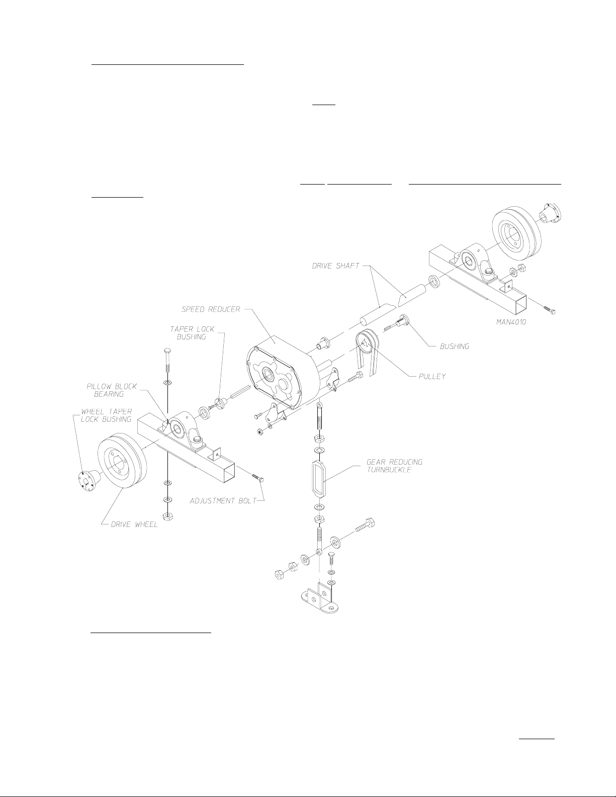
2. Tumbler (Basket) Drive System Replacement
a. Tumbler (Basket) Drive Wheel Replacement
1) Discontinue electrical service to the dryer.
2) Disconnect air supply to the dryer.
3) Remove front panels or rear panels that are secured to the front or rear tumbler section of the dryer
by removing the access bolts.
4) Remove the eight (8) 3/8-16 x 1" hex head bolts, along with the 3/8" flat washers and 3/8" lock
washers securing the panel to the tumbler (basket) section frame and swing the hinged panel out.
5) Disconnect the two (2) 1/4-inch poly-flo tubes connected to the load door piston.
6) Disconnect the following electrical connections;
• The front door position switch disconnect plug is located in the left hand side of the front doors.
Disconnect this plug and feed the cable through the hole located on the right side of the front panel.
• Intake temperature probe disconnect plug is located in the burner/heater section of the dryer just
above the 25 HP motor. Disconnect this plug and route through the hole located on the right side
of the front panel.
• The rear panel controls disconnect plug is located behind the rear panel controls. Disconnect this
plug and feed through the hole towards the left hand drum motor section.
• The rear door position switch disconnect plug is located on the left hand side of the rear doors.
Disconnect this plug and feed the cable through the hole located on the right hand side of the
tumbler (basket) section.
7) Swing the panel up far enough to gain access to the drive wheels.
8) Place a block of wood under the tumbler (basket) to prevent the tumbler from dropping on to the
frame.
9) Loosen the four (4) 5/8-11 x 5" bolts from the 2-inch pillow block bearing.
10) Loosen the two (2) 1/2-13 x 3-1/2" full thread adjustment bolts so that the drive wheel lines up with the
large hole in the frame.
11) Remove the bolts from the wheel taper lock bushing.
12) Insert the bolts into the threaded holes.
13) Tighten the bolts evenly for wheel removal.
14) Mark the inside of the tumbler (basket) drive shaft before removing the wheel taper lock bushing.
15) Loosen the set screws from the taper lock bushing.
32
Page 37

16) Remove the taper lock bushing.
17) Remove the drive wheel.
13) Tighten the bolts evenly for wheel removal.
18) To install new drive wheel, reverse Step #17 thru Step #3.
19) Reconnect air supply disconnected in Step #2.
20) Reestablish electrical power to the dryer.
b. 5 HP Drive Motor Replacement
1) Discontinue electrical service to the dryer.
2) Mark and identify the wires that will be removed for proper reinstallation.
3) Loosen the turnbuckle and remove the V-belts.
4) Remove the bolts securing the drive motor to the motor mount.
5) Remove the drive motor from the dryer.
6) Mark the inside of the drive shaft before removing the wheel taper lock bushing (for proper re-
installation)
7) Remove the taper lock bushing and motor pulley.
a) Remove the bolts securing the taper bushing.
b) Insert the bolts into the threaded holes and tighten the bolts evenly for pulley removal.
c) Loosen the set screws on the taper lock bushing and remove the bushing.
8) Measure the mark on the drive motor shaft to the end of the shaft.
9) Mark the shaft of the new drive motor to the measurements from the old motor.
NOTE: For proper belt replacement, the V-belts should be replaced in matched sets (both belts).
10) Align the taper lock bushing with the mark on the shaft of the new drive motor and install by tightening
the set screw.
11) Insert bolts into the holes of the taper lock bushing and thread into the motor pulley, then tighten
evenly.
12) Install new drive motor and hand tighten the bolts that secure the drive motor to the motor mount.
13) Reinstall the V-belts removed in Step #3.
33
Page 38

14 Check that the motor pulley is properly aligned.
15) Secure the drive motor to the motor mount.
16) Tighten the turnbuckle.
IMPORTANT: DO NOT OVERTIGHTEN TURNBUCKLE.
17) Rewire the new drive motor in the same sequence as the wiring that was removed in Step #2.
A wiring diagram is usually affixed to the side of the motor.
18) Reestablish electrical service to the dryer.
c. V-Belt Replacement
1) Discontinue electrical service to the dryer.
2) Loosen the turnbuckle a tighten the V-belts.
3) Install the new V-belts.
NOTE: For proper belt replacement, the V-belts should be replaced in matched sets (both belts).
4) Tighten the turnbuckle.
IMPORTANT: DO NOT OVERTIGHTEN V-BELTS.
5) Reestablish electrical service to the dryer.
d. Taper Lock Bushing and Drive Motor Pulley Replacement
1) Discontinue electrical service to the dryer.
2) Loosen the turnbuckle remove the V-belts.
3) Mark the inside of the drive motor shaft.
4) Remove the bolts securing the taper lock busing.
5) Insert bolts into the threaded holes on the motor pulley and tighten evenly for pulley removal.
6) Loosen the set screws on the taper lock bushing and remove the bushing.
7) Measure the mark on the motor drive shaft to the end of the shaft.
8) Install the new drive motor pulley.
9) Align the new taper lock bushing with marks on the shaft and install by tightening the set screws
34
Page 39

10) Insert bolts into the holes of the taper lock bushing and thread into the motor pulley, then tighten
evenly.
11) Check that the motor pulley is properly aligned.
16) Reinstall the V-belts removed in Step #2.
17) Tighten the turnbuckle.
IMPORTANT: DO NOT OVERTIGHTEN TURNBUCKLE.
18) Reestablish electrical service to the dryer.
e. Pillow Block Bearing Removal
1) Discontinue electrical service to the dryer.
2) Follow Step #2 thru Step #17 of the Tumbler (Basket) Drive Wheel Replacement instructions
on page 32 and page 33.
3) Carefully file the score marks on the drive shaft from the set screws and lightly sand the shaft with
a light grit sand paper before removing the pillow block bearings.
4) Loosen the set screws and remove the pillow block bearing.
5) For replacement of the pillow block bearings reverse the above procedure, Step #4 thru Step #2.
IMPORTANT: Remove the wooden blocks that were inserted under the tumbler (basket).
6) Reestablish electrical service to the dryer.
f. Gear (Speed) Reducer Replacement
35
Page 40

CAUTION: Replacement gear (speed) reducers are shipped without oil. Add proper amount (1.4
liters) of recommended lubricant before operating. FAILURE TO OBSERVE THESE
PRECAUTIONS WILL RESULT IN DAMAGE TO THE DRYER AND WILL
VOID THE WARRANTY.
CAUTION:
TO MUCH OIL IN THE GEAR REDUCER WILL CAUSE OVERHEATING and
TOO LITTLE OIL WILL RESULT IN GEAR FAILURE. CHECK THE OIL LEVEL
REGULARLY. FAILURE TO OBSERVE THESE PRECAUTIONS WILL
RESULT IN DAMAGE TO THE DRYER AND WILL VOID THE
WARRANTY.
1) Discontinue electrical service to the dryer.
2) Measure the distance of the gear (speed) reducer from the rear of the dryer to assist in positioning the
gear reducer on the drive shaft during reinstallation.
3) Follow Step #2 thru Step #4 of Pillow Block Bearing Removal instructions on page 35.
4) Loosen the turnbuckle and remove the V-belt.
Remove the bottom turnbuckle mounting bolt.
5) Remove the three (3) bolts from the taper lock bushing and insert two (2) of these bolts into the
threaded holes and tighten evenly to remove the taper lock bushing from the gear (speed) reducer.
6) Repeat Step #5 to remove the other taper lock bushing.
7) Slide the drive shaft through the hole in the frame of the tumbler section enough to remove the gear
(speed) reducer from the shaft.
8) Remove the gear (speed) reducer from the drive shaft.
9) Check the position of both the drain plug and the breather plug.
10) Check the turnbuckle mounting pad on the gear (speed) reducer for the correct application.
11) Install the new gear (speed) reducer on to the drive shaft along with the taper lock bushing and the
pillow block bearing (set screws in the pillow block bearing face the end of the drive shaft).
12) Slide the drive shaft back into position then install the drive and wheel taper lock bushing.
13) Properly align the gear (speed) reducer, pillow block bearings, and drive wheels on to the drive shaft
and secure/tighten.
14) Secure the gear (speed) reducer to the drive shaft by reinstalling the three (3) bolts into the taper lock
bushing and tighten evenly for proper mounting.
15) Repeat Step #14 to reinstall the other taper lock bushing.
16) Reinstall the bolt into the turnbuckle and mounting bracket.
36
Page 41

17) Reinstall V-belts and tighten the turnbuckle.
IMPORTANT: DO NOT OVERTIGHTEN TURNBUCKLE.
18) Prior to operating the new gear (speed) reducer, fill with 1.4 liters of SAE 90 gear oil.
19) Mount the pillow block bearing on the mounting pads (using the bolts that were removed).
IMPORTANT: DO NOT OVERTIGHTEN BOLTS.
20) Reverse Step #3 from the Pillow Block Removal instructions on page 35.
IMPORTANT: Remove the wooden blocks that were inserted under the tumbler (basket).
NOTE: Verify correct mounting position of the gear (speed) reducer. Make the necessary corrections
and/or adjustments to the gear reducer for proper mounting. Changing the drain plug, the
breather plug, as well as the turnbuckle mounting pad may be required.
NOTE: Inspect ALL of the work performed, checking for security of parts and proper alignment.
21) Reestablish electrical service to the dryer.
g. Retaining Wheel Replacement
1) Discontinue electrical service to the dryer.
2) Remove the front or the rear loading door side panels secured to the front or the rear of the dryer by
removing the sixteen (16) 5/16-18 x 3/4" tap bolts, along with the 5/16" flat washers and the 5/16" lock
washers.
3) Remove the hardware (i.e., bolt, flat washer, spherical washers, and hex nut) from the wheel mount.
4) Remove the retaining wheel that is to be replaced.
5) Install the new retaining wheel.
Reinstall the flat washer and then
the spherical washer on to the
3/8-16 x 3-1/4" bolt, then insert into
the hole of the retaining wheel. Add
the second spherical washer to the
bolt. Holding the retaining wheel
in position, slide the bolt through
the retaining wheel and out of the
hole on the other side of the mount
assembly. Add a 3/8" lock washer
along with a 3/8-16 hex nut to the
bolt hand tight.
37
Page 42

WARNING: ALL SERVICE and TROUBLESHOOTING SHOULD BE PREFORMED BY
A QUALIFIED PROFESSIONAL or SERVICE AGENT.
WARNING: WHILE MAKING ADJUSTMENTS, OBSERVE ALL SAFETY
PRECAUTIONS DISPLAYED ON THE DRYER or SPECIFIED IN THIS
MANUAL.
6) Reestablish electrical service to the dryer.
Proceed to Retaining Wheel Adjustment instructions immediately below.
h. Retaining Wheel Adjustment
1) With the dryer operating, turn the off-set hex hub on the retaining wheel until the wheel lightly spins,
then stops as the tumbler (basket) rotates. (This is the proper adjustment of the retaining wheels.)
NOTE: Over compression of the retaining wheels against the tumbler (basket) will cause premature
failure of the retaining wheels.
2) Tighten the 3/8-16 hex nut on the bolt once the proper adjustment has been achieved.
3) Discontinue electrical service from the dryer.
4) Replace the front or the rear loading door panels.
5) Reestablish electrical service to the dryer.
i. Drive Shaft Replacement
1) Discontinue electrical service to the dryer.
2) Follow Step #2 thru Step #7 of the Gear (Speed) Reducer Replacement instructions on page 35
and page 36.
3) Carefully place the gear (speed) reducer on the floor and continue to remove the drive shaft from the
dryer.
4) Measure ALL scribe marks from the old shaft and transfer the marks on to the new drive shaft for
proper component replacement.
5) To install new drive shaft reverse Step #4 thru Step #2.
CAUTION: USE EXTREME CARE WHEN SETTING RETAINING WHEEL TENSION.
PERSONAL INJURY MAY RESULT.
NOTE: Proper retaining wheel tension has been achieved when the wheel spins and stops when a slight
pressure is applied (to the retaining wheel itself).
6) Reestablish electrical service to the dryer.
38
Page 43

H. ROTATIONAL SENSOR ASSEMBLY
The rotational sensor is a self-contained, motion detector proximity sensor, designed to detect a predetermined
stopped drum (basket/tumbler) condition. The rotational sensor is used as a safety device, once the drum has
stopped rotating for more than 12-seconds. After this 12-second interval has been reached, the sensor goes into
an open state, removing power to PLC (Programmable Logic Controller) input #10. This interruption of power to
input #10 signals the PLC that there is a tumbler (basket) fault. This turns control relay #6 (CR6) off, which
opens the heat circuit. When the rotational sensor is active (closed) the indicator on the sensor is on. The
rotational sensor drops approximately 4 VAC when the dryer is active. When the rotational sensor is off, the is
an approximate 120 VAC voltage drop.
WARNING: UNDER NO CIRCUMSTANCES SHOULD THE OUTPUT OF THE
ROTATIONAL SENSOR BE GROUNDED. DAMAGE WILL RESULT. A
CURRENT LIMITING DEVICE IS REQUIRED.
1. Rotational Sensor
a. Rotational Sensor Replacement
1) Discontinue electrical service to the dryer.
2) Remove the tumbler (basket) section bottom left hand panel.
a) Remove the four (4) 5/16-18 x 2-1/4" bolts.
b) Remove the panel.
3) Remove the left tilt guard.
a) Remove the six (6)
5/16-18 x 3/4" tap
bolts.
b) Remove the guard.
4) Remove the cover from the tumbler
(basket) junction box.
5) Remove the two (2) wires that go to the
rotational sensor from the tumbler (basket)
junction box.
6) Remove the adjustment/mounting nut.
7) Cut tie wraps holding cable.
8) Remove rotational sensor.
9) To install new rotational sensor, reverse Step #8 thru Step #4.
10) Reestablish electrical service to the dryer.
39
Page 44

(1) Rotational Sensor Adjustment
Distance Adjustment;
• Pull the rotational sensor as far away from the basket (tumbler) as possible.
• Spin/rotate the basket (tumbler) until the target (target lines up behind one of the basket ribs)
is aligned with the rotational sensor.
Mark basket (tumbler) rib with tape.
• The rotational sensor
the target until there is a 3/16" gap.
Time Adjustment;
• Jog basket (tumbler) for 10-seconds.
• Time the rotational sensor (the
time is measured from the last
time the target (tapered rib) goes
by the rotational sensor and the indicator light
on the sensor goes out.
• The measured time
• If an adjustment is required, remove the adjustment cap on the proximity sensor.
• Turn potentiometer on the proximity sensor
• Retime the sensor.
• Adjust as needed.
has to be adjusted towards
has to be 12-seconds.
11) Reinstall the left tilt guard removed in Step #3 (refer to previous page [page 39]).
12) Reinstall the tumbler (basket) section bottom left hand panel removed in Step #2 (refer to previous
page [page 39]).
40
Page 45

I. TOP OF TUMBLER (Basket) TEMPERATURE DOOR ASSEMBLY
1. Intake Temperature Probe/Sprinkler Temperature Probe
The intake temperature probe and sprinkler temperature probe are 100 ohm (100 Ω) Resistive Temperature
Device (RTD) probes located on the top of the tumbler (basket) section of the dryer. The intake temperature
probe measures the intake temperature of the dryer and is monitored by the hi-temperature controller. The
sprinkler temperature probe measures the temperature in the tumbler (basket) section of the dryer and is
monitored by the sprinkler controller.
• There are ten (10) TEK screws that must be removed prior to the removal of the top cover. Both intake
temperature and sprinkler temperature RTD probes are located under the top cover.
a) Intake Temperature Probe/Sprinkler Temperature Probe Replacement
1) Discontinue electrical service to the dryer.
2) Remove the ten (10) 1/4-20 x 1/2" TEK screws securing the top cover to the tumbler (basket) section
of the dryer.
3) Lift outer edge of the top cover and remove the cover from the tumbler (basket) section.
4) Remove the wiring from the temperature probe (probe being replaced) from the terminal block which
is located in the junction box on the top of the tumbler (basket) section of the dryer.
5) Remove the compression fitting securing the temperature probe to the mounting plate.
6) To install new temperature probe, reverse Step #5 thru Step #2.
IMPORTANT: When reconnecting new temperature probe to the terminal block, verify correct wire
placement or the probe will be in alarm status or in an open condition.
7) Reestablish electrical service to the dryer.
41
Page 46

J. TUMBLER (Basket) ELECTRICAL COMPONENTS
1. Drive Motor Controls and Overloads
a) Thermal Magnetic Starter (TMS) Description
The thermal magnetic starter (TMS) is used as a safety device to manually disconnect the motor, thereby
protecting the motor from being damaged in a locked rotor condition. The overload has a dial setting on
the face of the device. To set the overload, refer to your specific electrical diagram. The overload is
specifically designed for motor applications. It has a current curve built into it so the initial high current
draw by the motor
a "START" (Black or Tan-1) and a "STOP" (Red-0). The overload must be in the "START" mode for the
motor to run.
b) Thermal Magnetic Starter (TMS) Replacement
1) Discontinue electrical service to the dryer.
2) Mark L1, L2, L3 and T1, T2, T3 on the wires to the thermal magnetic starter (TMS) for correct
reinstallation.
3) Set the amp (amphere) rating on the TMS according to the electrical schematic supplied with your
dryer.
will not trip the overload. On the face of the overload there are two (2) push buttons,
4) To remove the thermal magnetic starter, pull the tab on the bottom of the TMS, and lift upward.
5) To install new thermal magnetic starter (TMS), reverse Step # 4 thru Step #2.
6) Reestablish electrical service to the dryer.
42
Page 47

Auxiliary Contact Block Description
2.
The auxiliary contact block is mounted on the side of the overload. Its' function is to sense an overload trip,
thereby triggering a safety fault which will disable the drying cycle. A motor fault message will appear on the
display of the Telemecanique XBT unit.
a. Auxiliary Contact Block Replacement
1) Discontinue electrical service to the dryer.
2) Remove the thermal magnetic starter (TMS) from the din rail by pulling the tab on the bottom of the
contact block and lift upward.
3) Remove the two (2) wires going to the auxiliary contact block and label for correct reinstallation.
4) There are two (2) types of auxiliary contact blocks...one style has a screw and the other style has a
clip. In both styles, disassembly and assembly is recommended with the thermal magnetic starter
(TMS) in the "STOP" position.
a) To remove the style that has the screw from the TMS, simply remove the screw.
b) To remove the style that has the clip, simply push the clip and twist the auxiliary contact block to
remove.
5) To install new auxiliary contact block, reverse Step # 4 thru Step #2.
6) Reestablish electrical service to the dryer.
3.
Varistor (MOV [Metal Oxide Varistor]) Description
The varistor (MOV) is used to suppress any inductive electrical spikes produced by the energizing and coil
voltage.
a) Varistor (MOV [Metal Oxide Varistor]) Replacement
1) Discontinue electrical service to the dryer.
2) Loosen the screws marked A1 and A2 on the contactor.
3) Verify that no additional wires were inadvertently removed.
4) Reverse above procedure to install new varistor.
43
Page 48

SECTION VI
PLC (PROGRAMMABLE LOGIC CONTROLLER) SYSTEM
A. PLC (Programmable Logic Controller) DESCRIPTION
The heart of the dryer is a TSX17 PLC (Programmable Logic Controller) with twenty-one (21) inputs and twelve
(12) outputs. The TSX17 PLC also uses two (2) expansion modules, a relay output module with six (6) outputs,
and a 4 mA - 20 mA (milliamphere) analog input module with four (4) inputs. The operator interface for the
TSX17 PLC is the XBT digital display unit.
The TSX17 PLC's (Programmable Logic Controller's) main module zero ("0") inputs are as follows:
• The "0" is used to sense that the 110 VAC control voltage has been turned on via the master control relay. If
the master control failed to be turned on, the XBT unit will display "CNTRL VOLT OFF" (control voltage
off).
• Input 1 monitors the overloads (OL) for motors OL1, OL2, OL3, OL4, and on gas dryers OL8. The over-
loads have auxiliary contacts in them that are tied in series from the control voltage to Input 0,1. In a
case that an overload trips, the XBT unit will display a "motor fault."
• Input 0,2 is used to monitor that the burner fan is on during a heat cycle. (This is not used on steam dryers
and is tied to Input 0,10 on steam dryers.) In a case were there is a call for heat and the burner fan
does not turn on, the dryer will display a "heater fault."
• Input 0,3 main function is to sense if one (1) of the high limits have tripped due to excessively high
temperature in the dryer. If the high limit trips, the XBT unit will display "HI-TEMP FAULT."
• Input 0,4 monitors the gas pressure. If a high gas pressure or a low gas pressure situation arises, voltage is
removed from Input 0,4 causing a heat cycle to be discontinued and a "GAS SUPPLY FAULT" to
be displayed. On steam models, this input is tied to the PLC's (Programmable Logic Controller's)
110 VAC power source.
• Input 0,5 is used to sense a clogged lint screen or obstruction in the exhaust via an air switch that is located in
the lint collection area. A fault in the air flow produces an "AIR FLOW FAULT" message.
• Input 0,6 is used to monitor the front load door if this load door is closed by means of DS1, A (Door Switch 1,
A contacts). A drying cycle will not begin until Input 0,6 is on. If a cycle is started and the door is
open, the XBT unit will display "DOOR OPEN."
• Input 0,7 monitors the rear door via the DS2, A (Door Switch 2, A) contacts. A cycle
the doors are closed. If a cycle is started with the rear door open, the XBT unit will display "DOOR
OPEN." in the case of one (1) door dryer, Input 0,7 is tied to 110 VAC.
• Input 0,8 is used to monitor the two (2) lint drawers. This is achieved through two (2) proximity switches, one
for each lint drawer. There is a magnet on each of the lint drawers, which when aligned with the
proximity switch causes a contact closure which brings 110 VAC to Input 0,8. When a cycle is
started and a lint drawer is not closed, the XBT unit will display "CHK. LINT DRAWER" (check
lint drawer).
cannot be begin until
44
Page 49

• Input 0,9 is used to sense if the burner doors are closed. This is accomplished through DS4A and DS5A
(Door Switch 4, A and Door Switch 5 , A) contact sets. If a drying cycle is attempted, the XBT
unit will display "DOOR OPEN."
• Input 0,10 is used to monitor a stopped tumbler (basket) condition. An inductive proximity sensor is located
in the left wrapper of the tumbler (basket) section. Behind one of the ribs on the front side of the
tumbler (basket), a steel target is mounted. As the target passes the proximity switch, it turns its
output on (110 VAC), turning on Input 0,10. If the target does not pass the proximity switch within 12-seconds the output turns off, shutting the heat off and the XBT unit will display "DRUM
FAULT."
• Input 0,11 and Input 0,12 are used to determine that the dryer is in a level position before a drying cycle can
be initiated (started/run). Each set of tilting pistons has a level switch in conjunction
with it. If a drying cycle is attempted with a level switch in the normally open
position, the XBT unit will display "LEVEL FAULT."
• Input 0,13 is used as a Visual Display Only for dryers manufactured prior to January 31, 1997. On dryers
manufactured as of January 31, 1997, Input 0,13 still has no direct control and is used only as a
display. However, on dryers manufactured as of January 31, 1997, there is a proximity switch
used to sense that the exhaust probe access door is closed. If the door is open, the dryer will shut
down and a "DOOR OPEN" message will be displayed via the TSX17 Programmable Logic
Controller (PLC) Input 0,9.
• Input 0,14 is used to sense that the burner controller has turned on the incoming gas valve during a heat cycle,
which in turn activates the heat reclaimer.
• Input 0,15 and Input 0,16are used as an operator interface in conjunction with the pendent. With 110 VAC
on, Input 0,15 the dryer will prepare for loading. The load door will open and
depending on options and programming, the dryer may tilt (
0,15 or Input 0,16 on, the dryer will level, close door, and a drying cycle can be
initiated (started). Input 0,16 is used for unloading, open door, and if applicable, the
rear will tilt up.
• Input 0,17 is used for Jog Forward. It turns/spins the tumbler (basket) in a clockwise (CW) rotation while in
a load or unload condition.
• Input 0,18 is used for Jog Reverse. It turns/spins the tumbler (basket) in a counterclockwise (CCW) rotation
while in a load or unload condition.
• Input 0,19 is only used on dryers manufactured with Rear Doors. When Input 0,19 is on, the rear doors will
open and the front of the dryer will tilt to unload if the pistons as well as the software are
configured for this operation. If Input 0,15 or Input 0,16 are on, then Input 0,19, will have no affect
on the dryer
• Input 0,20 (Drum Reverse) and Input 0,21 (Drum Forward) are used to jog the load during a rear panel un-
load (Input 0,19 on).
Front Up). With Input
45
Page 50

The main module of the TSX17 PLC (Programmable Logic Controller) also has eleven (11) outputs to control
various functions of the dryer. The outputs are relay contacts, whereby each of the relays have a common
terminal tied to 110 VAC.
• Output 0,0 is used to control the Main Blower Contactor. On a call for fan, the output supplies 110 VAC to the
coil of the fan motor contactor. As long as none of the overloads have tripped, the contactor will
engage (pull in) starting the dryer.
• Output 0,1 activates the
two (2) 5 horsepower (HP) drive motors.
• Output 0,2 is used to reverse the direction of the drive motors.
• Output 3 was previously used to activate an intended lint collection system. The output was to be used from
the beginning of a cycle until 1-minute after the completion of the cycle.
• Output 4 is used to initiate the burner controller at the beginning of a heat cycle. During a heat cycle, the out-
put stays on enabling the standing pilot to be active (on) as long as the burner controller safeties
have all been met. If ALL the safeties are met, the incoming gas valve will turn on. This puts the
dryer in a high fire standby.
• Output 5 is used to cycle high fire on and off in conjunction with Output 4 during the heat cycle. This is the
output that maintains the set point temperature.
• Output 6 and Output 7 are used to control the Main Load Door. Output 6 controls the load door opens
• Output 8 and Output 9 are used to control the Rear Door. Output 8 controls the unload door open solenoid
Drum (tumbler) Forward Contactor, which starts the tumbler (basket) running via the
solenoid (S1) and Output #7 controls the load door close solenoid (S2).
(S3) and Output 9 controls the unload door close solenoid (S4).
• Output 10 is the Front Up control. When it turns on, 110 VAC is supplied to the front up solenoid (S5) through
the rear door level switch (LS2B).
• Output 11 controls the Front Door solenoid (S6). When 110 VAC is supplied to the front door solenoid, air is
supplied to the top ports of the piston leveling the dryer.
Due to the amount of outputs needed, an additional output module is added to the TSX17 PLC (Programmable
Logic Controller). This output module consists of relay contacts with the common tied to 110 VAC.
• Output 1,0 is used to tilt the rear of the dryer up for unloading purposes. If the front of the dryer is up, the front
door level switch (LS1B) closed to allow the rear up solenoid (S7) to engage.
• Output 1,1 supplies 110 VAC to the rear down solenoid (S8).
• Output 1,2 and Output 1,3 are used to control the position of the Heat Reclaimer. When Output 1,2 is on, the
heat reclaimer is in the exhaust air mode. ALL the air moved by the blower goes
out of the exhaust. When Output 1,2 turns off and Output 1,3 turns on, the dryer
goes into a recirculating mode (heat reclaimer on) whereby a percentage of the air
no longer goes out of the exhaust but goes over the burner as preheated air. The
heat reclaimer is on as long the dryer is in a heat mode.
46
Page 51

• Output 1,4 is the blower (fan)
the
Air Jet turns on for 30-seconds.
• Output 1,5 is the End of Cycle light. Once the dryer has reached the end of a cycle, the output turns on,
illuminating the
asserted on the pendant.
ANALOG INPUT MODULE
The Analog Input Module is used to measure the temperature in the exhaust of the dryer. The Analog Input
Module measures a 4 mA - 20 mA (milliamphere) signal (controlled by the TX58 Resistive Temperature
Device [RTD] in conjunction with the 100Ω (100 ohm) Platinum Resistance Thermometer and converts it to
a corresponding temperature. The RTD has predetermined temperature to resistance characteristics. The
following chart has a few examples;
Air Jet which is used to clean lint off of the fan (blower). At the end of a cycle,
End of Cycle light. The output will turn off once a load or unload command is
Fº Cº R
ESISTANCE
(Ω)
230 001
5742901
6803111
9913948.531
The TX58 RTD (Resistive Temperature Device) converts the resistance of the RTD to a 4 mA - 20 mA
(milliamphere) current loop. The current in the loop is equal to .022222 mA/(ºF - 32) + 4 mA (measurement
in celsius [centigrade] is .04 mA/ºC + 4 mA.
Example: 200º F - 32 = 168 x .022222 = 3.73 mA + 4 mA = 7.73 mA
93º C x .04 mA = 3.72 + 4 mA = 7.72 mA
The power source for the TX58 RTD is PS1 (Power Supply 1) is a 24 VDC power supply mounted on the
main electrical panel.
NOTE: There is approximately a 10º F (18º C) differential between the actual and the displayed
temperature on the XBT unit.
TELEMECANIQUE XBT UNIT
The
Telemecanique XBT Unit is the user interface to the dryer. ALL the user commands are loaded into the
XBT unit at the factory. System parameters are stored in the TSX17 PLC (Programmable Logic Controller)
via the XBT unit interface. These are the drying recipes and parameters such as Load Level, Spin Time,
Dwell Time, etc. The power source for the XBT unit is a 24 VDC power supply mounted on the main
electrical panel. A data cable connects the XBT unit to the TSX17 PLC for communication purposes.
HOUR CLOCK
The dryer has a Hour Clock to keep track of how many hours the dryer has been running. The clock runs off
the 24 VAC power supply through a set of contacts on the blower contactor. When the blower contactor
closes, it also closes an additional set of contacts to activate the clock.
47
Page 52

B. PLC (Programmable Logic Controller) COMPONENT REPLACEMENT
1. TSX17 PLC (Programmable Logic Controller) Assembly
The TSX17 Programmable Logic Controller (PLC) is made up of three (3) components. The first and main
component is the TSX17 PLC, then the Relay Outputs, and the Analog Inputs. The TSX17 PLC has a ram
back-up lithium battery.
a. TSX17 PLC (Programmable Logic Controller) Component Replacement
1) Discontinue electrical service to the dryer.
2) Remove the coaxial (coax) cable from the TSX17 PLC.
3) Remove the four (4) screws securing the two (2) smoke colored bus terminal strips from the top and
bottom of the TSX17 PLC.
4) Remove the two (2) screws securing the buss terminator from the TSX17 PLC.
5) Lift the cover off of the relay output component.
6) Remove the buss terminator from the TSX17 PLC.
7) Insert a standard flat head screwdriver into the "red" or "orange" tab and push down. At the same
time, lift upward on the TSX17 PLC. This will remove the PLC from the rail.
8) To install new TSX17 PLC, reverse Step #7 thru Step #2.
9) Reestablish electrical service to the dryer.
2. Relay Output/Analog Input Module
a. Relay Output/Analog Input Module Replacement
1) Discontinue electrical service to the dryer.
2) Mark and identify the wires that will be removed for proper reinstallation.
3) Lift the cover off of the relay output and analog input then remove the two (2) screws securing the
buss terminator to the module.
a) The buss terminator must also be removed from the TSX17 PLC and moved aside.
4) Insert a standard flat head screwdriver into the "red" or "orange" tab and push down. At the same
time, lift up on the module being replaced.
5) To install new module, reverse Step #4 thru Step #2.
6) Reestablish electrical service to the dryer.
48
Page 53

3. Lithium Battery
a. Lithium Battery Replacement
1) Discontinue electrical service to the dryer.
2) Remove the battery cover which is located directly above the buss terminator on the TSX17 PLC
(Programmable Logic Controller) by sliding the cover in an upward direction.
NOTE: The lithium battery is attached to the cover and plugged into the module.
3) Remove the plug from the module, then remove the battery from the cover.
4) To install new lithium battery, reverse Step #3 thru Step #1.
49
Page 54

4. Under Voltage Disconnect
The dryer uses a 110 VAC under voltage disconnect. This 110 VAC is supplied from the sprinkler circuit.
The sprinkler circuit is part of the safety circuit of the dryer. If the sprinkler circuit is in an alarm condition,
the 110 VAC supply to the under voltage disconnect will become discontinued, shutting down the dryer.
NOTE: For steam models that do not have the sprinkler option skip Step #4.
a. Under Voltage Disconnect Replacement
1) Discontinue electrical service to the dryer.
2) Mark and remove wires from L1, L2, and L3.
3) Mark and remove wires from L4, L5, and L6.
4) Mark and remove wires from L and N.
5) Loosen and remove the door handle extension from the under voltage disconnect.
6) Remove the two (2) #8-32 x 2" Phillips round head machine screws.
7) To install new under voltage disconnect, reverse Step #6 thru Step #2.
8) Reestablish electrical service to the dryer.
50
Page 55

5. Hi-Limit Controller
The dryer utilizes six (6) channel controller (HLC-1) to monitor various locations on the dryer for over
temperature faults. The hi-limit controller enables the dryer to continually monitor up to six (6) Resistive
T emperature Devices (R TD's) at one time. Each channel is individual with set points. The hi-limit controller
scans each channel, and in the event of an alarm, the scanning will halt (stop), and the Single-Pole-DoubleThrow (SPDT) will change states signaling a fault. The hi-limit controller will remain in alarm until the reset
button is pushed and the temperature has fallen below the set-point temperature. The scan rate can be
adjusted from 4 to 12-seconds per channel.
• Channel #1 is used to monitor the exhaust for an over temperature situation.
• Channel #2 is used as an over burner monitor (for Gas Models Only).
• Channel #3 is used to monitor intake temperature (for Gas Models Only).
• The remaining channels are spares that can be used for future expansion.
a. Hi-Limit Controller Replacement
1) Discontinue electrical service to the dryer.
2) Loosen the four (4) screws hold the hi-limit mounting
bracket.
3) Slide the mounting bracket off of the screws through the
keyhole.
4) Disconnect the plug going to the hi-limit controller.
5) Remove the two (2) screws holding the mounting slides.
6) Remove the two (2) slides.
7) To install new hi-limit controller, reverse Step #6 thru Step #2.
8) Reestablish electrical service to the dryer.
HI-L
IMIT CONTROLLER TEMPERATURE SPECIFICATIONS
G
AS
ºF ºC
HI-L
IMIT NAME
ºF ºC
S
TEAM
HI-L
Current
Production
Past
Production
IMIT NAME
RTD 1 2 2 5 107 Exhaust Temp. Limit 2 2 5 107 E xhaus t Temp . Limit
RTD 2 200 93 Over Burner Temp. 650 343 Intake Temperature
RTD 3 650 343 Intake Temperature 500 260
RTD 4 5 0 0 2 60
RTD 5 5 0 0 2 60
N/A*
N/A*
500 260
500 260
RTD 6 5 0 0 2 60 N /A * 5 00 2 6 0
* Not appl icable. ..co ntro ller chan nels mu st be s et to 500º F (260 ºC).
51
N/A*
N/A*
N/A*
N/A*
Page 56

6. Gas Burner and Ignition System
The dryer's gas burner system operates on a on or off gas rate sequences to accurately control the tumbler’s
(basket's) drying temperature. Maximum firing rate is 2.8 million btu/hr.
Upon a call from heat, the dryer computer sends a 120 volt signal to the burner controller module (BCM)
which initiates and controls the ignition sequences. The BCM insures that
closed before turning on the combustion air burner fan, then checks to ensure that the burner fan air switch
has closed. The pilot gas flame is then established, the flame rod, (which sits in this pilot flame), comes in
contact with the flame and signals the BCM. The main motorized gas valves open in sequence, and full
operational flame is achieved.
The burner controller module (BCM) has five (5) L.E.D.’s on its cover and two (2) neon’s on the mounting
base for ease of troubleshooting, as well as dip switches inside for ease of programming.
ALL the safety switches are
The burner controller module controls
gas valve. When the drying set point temperature is reached, the dryer’s computer closes the top
motorized gas valve, shutting off full flame.
ALL of the gas burner ignition components, except for the motorized
52
Page 57

a. Major Burner Components
1) Burner Controller Module (BCM)
The burner controller module (BCM) provides effective burner flame safeguard control through
adjustable purge and trial-for-ignition timing. The BCM insures that ALL dryer safety switch circuits
are closed, delays ignition to allow the combustion chamber to vent, and insures that a healthy pilot
flame is established before opening the main gas valves. Five (5) L.E.D.’s (light emitting diodes)
on the cover of the BCM allow for easy troubleshooting. Dip switches on the back of the module
allow for easy programming.
(a) Dip Switches Selections
(1) Loosen the two (2) screws on the burner control module cover and pull the module cover off
of its base. The dip switches are on the back of the cover.
Switch #1 - Recycling Mode
With this switch in the “ON” position, the burner will recycle the ignition sequence once during
each drying cycle after a burner fan air switch or main flame failure, but only if the failure
occurs more than 35-seconds after ignition. If this switch is “OFF," the burner will lock out at
once.
Switch #2 - Intermittent Pilot
This switch is “ON” for intermittent pilot or “OFF” for interrupted pilot. ADC utilizes intermit
tent pilot so that the pilot flame stays lit during the entire drying cycle. With interrupted pilot,
the pilot flame would go out once the main flame is established. This is used mainly on oil
burners lit by a gas pilot.
Switch #3 - Trial for Ignition (TFI) Time
When this switch is “ON” a Trial for Ignition (TFI) of ten (10) seconds is set. If it is in the
“OFF” position, the TFI is five (5) seconds. The Trial for Ignition Time is the length of time
that the pilot is given to light. A ten (10) second TFI is best for the dryer.
Switch #4, Switch #5, Switch #6, Switch #7- Purge Time
Switch #8 is for post purge selection.
With switch #8 in the "ON" position,
the post purge time will be 15-seconds.
When switch #4, switch #5, switch #6,
and switch #7 are in the “OFF”
position, the post purge time
seconds.
will be 0-
53
Page 58

b. L.E.D. (Light Emitting Diode) and Neon Displays of the BCM (Burner Controller Module)
1) Operating Interlock - L.E.D. is lit when;
ALL safety interlock switches are closed, applying a 110 VAC signal to terminal #7 of the burner
controller module (BCM).
2) Operating Interlock - L.E.D. is not lit when;
One (1) or more safety interlock switches (burner doors, load door, optional unload door, gas pressure,
lint pressure, hi-temp alarm contacts, tumbler [basket] stopped, and lint drawer) are open. If any of
the safety interlocks switches are open the burner ignition sequence will not be attempted.
3) Air Failure - L.E.D. is lit if;
• Burner fan air switch is not closed within 10 seconds of start-up of blower
• Burner fan air switch is open during firing cycle.
4) System Unsafe - L.E.D. is lit if;
• A loose connection on the flame rod or spark plug.
•
ALL purge time dip switches are in the off position.
• Flame is detected out of sequence.
• Inductance is detected on sensor wires.
• Wiring fault on terminals #3, #4, and #5.
• An internal controller failure.
• Air switch closed before start-up.
5) Flame Signal - L.E.D. is lit when;
• The flame rod is in contact with the pilot flame and the burner controller module (BCM) converts
a microampere (microamp) current between the flame rod and ground into a three (3) 11 volt DC
signal that can be measured on the BCM. Inset one (1) probe of a DC volt Meter into the flame
signal port and put the other probe to ground. The meter will read out the three (3) 11 volt DC
flame signal. If the flame signal L.E.D. (light emitting diode) flickers on and off, this is a result of
a weak flame signal which can be caused by an intermittent wiring connection between the flame
rod and BCM, a faulty ground connection, bad ground of the dryer, weak pilot flame or dirty or
defective flame rod.
6) Burner Controller Power On Indicator - Neon is lit when;
• Burner Controller has its supply voltage of 120 VAC.
7) Burner for Air Switch Status Indicator - Neon is lit when:
• Air switch is closed after start-up of blower (fan) and interlocks are ALL closed.
54
Page 59

8) Burner Fan Air Switch Status Indicator - Neon is not lit;
• Air switch is not closed after start-up of burner fan.
• Door interlocks are open.
• A Combustion burner screen is clogged.
• A door on the dryer is open.
9) Test/Reset Button
When this button is pushed in, the burner controller module (BCM) will halt the ignition sequence,
once the pilot flame is established. This allows the pilot flame to be adjusted.
c. Flame Rod and Spark Plug
The pilot flame is lit by the spark plug, while flame sensing is done through the flame rod. The spark plug
is energized when the pilot solenoid slave opens, igniting the pilot flame. The flame rod sits in the pilot
flame and sends a 3 volt DC to 11 volt DC signal to the burner controller module when it is in contact with
the pilot flame. The pilot flame should be about the size of a tennis ball and should heat the flame rod so
it is red hot.
d. Burner Fan System
The burner fan provides additional combustion air for proper gas combustion. The fan provides approximately
900 cfm of air in this burner box. The airflow is obtained when the air pressure is measured at the air
pressure tap on the gas burner box approximately 1.25-inches water (3.1 millibars). The combustion air
system is comprised of the components described on
page 53 and page 54.
55
Page 60

1) Burner Fan Air Switch
The differential in air pressure is measured by the burner fan air switch, which is located next to the
burner fan motor. If the combustion air is inadequate, this switch will prevent ignition. The setting of
this switch is adjustable, and it should be set at approximately .59-inches (15 mm) of water column
(W.C.) because of slight variances in spring tension characteristics, range settings, and markings are
nominal.
2) Burner Fan and Motor
The combustion air is produced by a 6-1/4" squirrel cage fan attached to a 1-1/2 HP, 3,600 RPM
motor. The motor must spin counterclockwise (CCW) as viewed from the rear of the motor.
3) Combustion Air Lint Filter
The combustion air lint filter is made of a fine mesh stainless steel screen which must be cleaned
regularly. This screen prevents any lint from entering the burner box.
56
Page 61

4) Combustion Air Damper
To produce the required combustion airflow, this damper can be adjusted. Remove the screen to get
access to the damper. Moving the damper closer to the blower inlet opening will reduce the combustion
airflow, and moving it away from the blower inlet opening will increase the airflow. To measure the
combustion airflow, attached a manometer to the air pressure tap on the burner box. The air pressure
should measure 1.25- inches (31.75 mm) to 1.5-inches (38.1 mm) water column (W.C.).
e. Pilot Gas Supply Line
1) The pilot gas supply line consists of a manual shut-off valve, pressure regulator, electric solenoid valve,
back-loaded pressure regulator, and an adjustable gas cock.
2) The gas pressure in this line should be approximately 3.5-inches (88.9 mm) water column (W.C.) for
natural gas and 1.5-inches (38.1 mm) water column for L.P. (liquid propane) gas. This will provide
a bushy pilot flame, which produces a signal through the flame rod that is converted to 3 to 11 volts DC
in the burner controller module (BMC).
a) This flame can be adjusted in two (2) ways.
(1) Pilot Inlet Pressure Regulator
Remove the cap and turn the slotted adjustment screw clockwise (CW) for more gas and
counterclockwise (CCW) for less gas.
(2) Adjustable Pilot Gas Cock
Remove the cap and turn the slotted adjustment screw clockwise (WC) for less gas and
counterclockwise (CCW) for more gas.
b) The pilot line contains a back-loaded pressure regulator with an impulse line connected to the gas
burner inlet. The regulator will maintain a constant pilot supply pressure in the burner due to an
increase in temperature.
f. Main Gas Supply Line
The main gas supply line consists of a pressure regulator, two (2) motorized shut-off valves, HI/LO gas
pressure switch, manual shut-off valve.
The gas pressure at the burner should be 2.5-inches (63.5 mm) water column (W.C.) for natural gas and
1.25-inches (31.8 mm) water column for L.P. (liquid propane) gas. This pressure is measured by a
manometer at the manual shut-off valve just top motorized valve.
1) Motorized Gas Valve
DO NOT adjust this regulator.
The two (2) 2-inch F.P.T. motorized valve are “ON/OFF” gas flow control valves. The valves motors
operate on 120 VAC and are electrically “cascaded” so that upper valve will not open until lower valve
has fully opened. A limit switch inside the lower motorized valve provides the signal that the valve is
fully opened. These valves will open only when the burner controller module (BCM) is receiving a
signal from the flame rod proving that the pilot flame is established.
57
Page 62

Top Motorized Gas Valve
The valve sets the gas rate of 2,800,000 btu/hr (705,290 kcal/hr). To achieve this rate, the gas pressure
must be set for 2.5-inches (63.5 mm) water column for natural gas and 1.25-inches (31.8 mm) water
column for L.P. (liquid propane) gas. To adjust. loosen the pan head screw located on the front of the
top motorized valve, while holding the valve body, turn the flow adjustment clockwise (CW) for less
gas and counterclockwise (CCW) for more gas. Retighten the pan head screw when correct gas flow
is achieved. There is a switch located on the back of the top gas valve that verifies valve closure. The
burner controller module (BCM) will go into a system unsafe error and the burner
burner sequence.
2) Sequence of Operation
With dryer power on, a 120 volt signal is sent to terminal #1 and terminal #2 of the burner controller
module (BCM). A power indicator light has been added to the controller base for troubleshooting.
a. Drying cycle is started
b. Dryer computer calls for heat.
will not begin a
58
Page 63

c) The burner controller module (BCM) checks that
(terminal #7 of the [BCM]). If this is the case, then the green “operating interlocks” L.E.D. (light
emitting diode) on the BCM will light. If a safety switch is open, the green L.E.D.
the red “SYSTEM UNSAFE” L.E.D. will light. The ignition sequence will stop.
ALL safety switches are closed, the BCM will start the burner fan motor (BCM terminal #8).
If
The BCM waits 10-seconds to allow the blower motor to get up to speed, and then checks that the
burner fan combustion air switch (BCM terminal #6) circuit is closed. If this circuit is open during
the drying cycle, the “Air Failure” L.E.D. will light. The gas valve will close, and a “HEATER
FAULT” message will be displayed.
In order to prevent this air switch from being jumped out, the BCM checks to insure that this circuit
is open prior to start-up, then “SYSTEM UNSAFE” L.E.D. will light.
If the air flow switch closes after the burner fan is turned on, the pilot solenoid valve (BCM
terminal #3) is opened for ten (10) seconds, and a spark is produced (BCM terminal #4) by the
burner spark plug, igniting the pilot flame.
The flame rod, which extends into the pilot flame, has 300 VAC on it from the BCM (terminal
#S1). The flame lets the current flow from the flame rod to ground, which is then converted to 3 to
11 volts DC by the BCM. The “flame signal” L.E.D. on the BCM lights up.
ALL of the dryer’s safety circuits are closed
will not light, and
The spark plug will turn off 1.5-seconds after the pilot flame is detected. If the pilot flame should
fail during the ten (10) seconds period that the pilot solenoid is open. The BCM will reenergize the
spark. If the pilot flame is not established at the end of this 10-second period, the system will lock
out and the “FLAME FAILURE” L.E.D. will light.
The 10-second period when the pilot solenoid opens and a spark is produced is called the trial-forignition (TFI) time. It is selected at either 5-seconds or 10-seconds by a dip switch located on the
back cover of the BCM.
The 3 volt DC to 11 volt DC signal from the flame rod to the BCM can be measured by;
(1) Closing the manual shut-off valve in the main gas line to the burner. Leave the pilot manual
valve open.
(2) Push the Test and Reset button on the cover of the burner control module in to the “test”
position.
(3) Start a drying cycle...
The burner controller module (BCM) will halt the ignition sequence after the pilot is ignited.
The pilot flame should be about the size of a tennis ball and should make the flame cord red
hot.
(4) Insert the positive probe of a DC Volt Meter in to the “flame signal” port on the cover of the
burner controller module (BCM). Connect the negative probe to ground.
59
Page 64

(5) If signal is less than 3 volts DC, then the pilot may be too small or too large, there may be a
wiring connection between the flame rod and burner controller module (BCM), the flame rod
may be dirty, (wash it with soap and water) or defective, or the grounding may be faulty.
Once the flame probe signal is detected by the BCM, it waits 5-seconds to allow the pilot to
stabilize and then opens the main motorized gas valves (terminal #5 on the BCM) in sequence.
The lower valve opens first. Upon full opening, its external switch closes, enabling the second
motorized valve to open and full flame to be achieved.
If flame failure occurs within 35-seconds period, the BCM will recycle the ignition sequence
once. If flame fails a second time, the system will lock out and the “FLAME FAILURE” pilot
will light.
Once main flame is established, the burner will remain in the full fire mode until the drying set
point temperature has been reached. At this point, the dryer computer will cycle the top
motorized gas valve closed the position. The “OFF” mode will be maintained until the dryer’s
temperature falls below the drying set point temperature. The motorized valve will then be
returned to the full fire position. The ON/OFF motor of the motorized valve, it moves to the full
fire position. “OFF” is achieved when no voltage is applied to the motorized valve.
g. Gas Burner Start-Up
1) New gas lines are filled with air and must be purged before the burner will light. To do this close the
upper manual shut-off valve, but leave the pilot line shut-off open. Push in the test and reset button on
the cover of the burner controller module (BCM). This will “freeze” the ignition sequence when the
pilot flame ignites. This allows time to examine the pilot flame, and measure the flame rod signal to the
BCM.
2) Connect a pressure gauge or water tube to the pilot gas pressure tap. Start the dryer. Follow the
ignition process by referring to the “Sequence of Operation” section of this manual.
3) When the pilot flame is ignited, the pilot gas pressure should measure 3.5-inches (38.1 mm) water
column (W.C.) for natural gas and 1.5-inches (88.9 mm) water column (W.C.) for L.P. (liquid
propane) gas. The pilot flame should be about as big as a tennis ball.
4) Once the pilot has been properly set, remove the pressure gauge from the pilot line connect a differential
pressure gauge between the main gas pressure tap (HI port) and the air pressure tap (LO port) on the
side of the gas burner box. The lines connecting the gauge to these taps must be long enough to allow
the gauge to sit outside of the dryer so that the burner section access door can be closed when the
dryer runs. Running the dryer with these doors open will give an incorrect air pressure reading.
5) Once this differential gauge is installed, open the main gas shut-off valve and push the test and reset
button on the burner controller module (BCM) so that the button springs out. Restart the dryer. The
ignition process should now continue to the full gas flow state. The differential gauge should read
2.5-inches (63.5 mm) water column (W.C.) for natural gas and 1.25-inches (31.8 mm) water column
(W.C.) for L.P. (liquid propane) gas. If it does not, adjust the top gas valve as described in “Top
Motorized Gas Valve” on
page 58.
60
Page 65

h. Burner Air Switch
The dryer uses a burner air switch on its burner components. The differential air pressure is measured by
this air switch, which is located next to the burner fan motor. If the combustion air is inadequate, this
switch will prevent ignition. The setting of this burner air switch is adjustable, and is preset at the factory.
1) Burner Air Switch Replacement
(a) Discontinue electrical service to the dryer.
(b) Remove the two (2) 1/4" x 1/8" M.P.T.
straight brass connectors from the burner
fan air switch.
(c) Remove the 5/16-18 x 3/4" tap bolt as well
as the 5/16" lock washer.
(d) Mark and identify the wires for correct re-
placement on the new burner air switch.
(e) Remove the cord grip from the burner fan
air switch.
(f) To install new burner air switch, reverse Step #e thru Step #b.
Reestablish electrical service to the dryer
(g) .
61
Page 66

i. Burner Squirrel Cage Fan Components
The combustion air is produced by a 6-1/4" squirrel cage fan, attached to a 1-1/2 HP, 3,600 RPM motor.
This motor must spin counterclockwise (CCW) as viewed from the rear of the motor.
1) Burner Fan Motor
a) Burner Fan Motor Replacement
(1) Discontinue electrical service to the dryer.
(2) Remove the four (4) #8-18 x 7/16" TEK screws which secure the inlet ring to the combustion
air blower housing.
(3) Remove the two (2) 1/2-20 left hand jam nuts as well as the 1/2-inch flat washer.
(4) Remove the 6-1/4" squirrel cage fan.
(5) Remove the motor cover plate to reveal the wiring.
(6) Mark and identify wiring for correct replacement on to the new motor.
(7) Remove the cord grip and wiring harness from the motor.
(8) Remove the four (4) 3/8-16 x 3/4" hex head bolts securing the motor to the combustion air
blower housing.
(9) To install new burner fan motor, reverse Step #8 thru Step #2.
(10) Reestablish electrical service to the dryer.
2) Burner Fan Squirrel Cage
a) Burner Fan Squirrel Cage Replacement
(1) Discontinue electrical service to the dryer.
(2) For removal of the 6-1/4" squirrel cage fan, follow Step #2 thru Step #4 of the Burner Fan
Motor Replacement instructions above.
62
Page 67

(3) For replacement of new 6-1/4" squirrel cage fan, reverse Step #4 thru Step #2 of the Burner
Fan Motor Replacement instructions on the previous page (
(4) Reestablish electrical service to the dryer.
3) Burner Fan Electrical Components
a) Burner Fan Thermal Magnetic Starter (TMS)
The thermal magnet starter (TMS) is used as a safety device to manually disconnect the motor so
that it will be protected from damage in the event of a locked rotor condition. The overload has a
dial setting on the face of the device. To set the overload, refer to the specific electrical diagram.
The overload is specifically designed for motor applications. It has a current curve built into it so
the initial high current draw by the motor will not trip the overload. On the face of the overload are
two (2) push-buttons; "START" (Black or Tan) and "STOP" (Red - 0). The overload has to be in
the "START" mode for the motor to run.
(1) Thermal Magnetic Starter (TMS) Replacement
(a) Discontinue electrical service to the dryer.
(b) Mark L1, L2, L3, and T1, T2, T3 on the wires to the TMS for correct replacements.
page 62).
(c) Set the amp (amphere) rating on the TMS according to the electrical schematic supplied
with the dryer.
(d) To remove the thermal magnetic starter (TMS), pull the tab on the bottom of the TMS and
lift upwards.
(e) To install the new thermal magnetic starter (TMS), reverse Step d thru Step b.
(f) Reestablish electrical service to the dryer.
(2) Auxiliary Contact Block
The auxiliary contact block is mounted on the side of the overload. Its function is to sense an
overload trip, thereby triggering a safety fault which will disable the drying cycle.
(a) Auxiliary Contact Block Replacement
(1) Discontinue electrical service to the dryer.
(2) Remove the thermal magnetic starter (TMS) from the din rail by pulling the tab on the
bottom of the auxiliary contact block and lift upwards.
(3) Remove the two (2) wires going to the auxiliary contact block and label them for
correct reinstallation.
(4) There are two (2) types of auxiliary contact blocks...one type has a screw and the
other type has a clip. In either type, disassembly and assembly is recommended with
the thermal magnetic starter (TMS) in the stop position.
63
Page 68

(5) To install the new auxiliary contact block, reverse Step #4 thru Step #2.
(6) Reestablish electrical service to the dryer.
(3) Varistor (Metal Oxide Varistor [MOV])
The metal oxide varistor (MOV) is used to suppress any inductive electrical spikes produced
by the energizing and collapsing of coil voltage.
(a) Varistor (Metal Oxide Varistor [MOV]) Replacement
((1)) Discontinue electrical service to the dryer.
((2)) Loosen the screws marked A1 and A2 on the contactor.
((3)) Verify that no additional wires were inadvertently removed.
((4)) To install the new metal oxide varistor (MOV), reverse Step #3 thru Step #1.
j. Burner Door Switch
The burner door switch is a part of the dryer's safety circuit. If at any time during a drying cycle the
burner doors are open, the Programmable Logic Controller (PLC) Input #9 will go off, shutting the dryer
down and displaying "DOOR OPEN." (Verify that the burner door switches
are not out of adjustment.)
a) Burner Door Switch Adjustment
1) With burner doors closed, verify if PLC (Programmable
Logic Controller) Input #9 is off.
2) Loosen the 1/4-20 x 3/4" hex head machine
bolts.
NOTE: Adjust one switch at a time.
3) Adjust the burner door switch to
the outside of the dryer and
tighten the 1/4-20 x 3/4" hex
head machine bolts.
4) Close the burner doors and
verify if PLC Input #9 is on. If
PLC Input #9 is off, adjust the
other burner door switch.
64
Page 69

b) Burner Door Switch Replacement
1) Discontinue electrical service to the dryer.
2) Loosen the 1/4-20 x 3/4" hex head machine bolts as well as the 1/4-20 hex nut.
3) Remove the four (4) Phillips head screws securing the burner switch cover plate to the switch
body.
4) Mark, identify, and remove the wires from the burner door switch for correct replacement.
5) Remove the cord grip from the switch body.
6) To install new burner door switch, reverse Step #5 thru Step #2.
7) Reestablish electrical service to the dryer.
Steam Heat System
7.
The steam dryer uses six (6) steam coils to produce a heat input of 60 Bhp (boiler horsepower). The dryer
utilizes three (3) separate dampers to direct air in the drying process or cool down process of a cycle.
The first damper is the cool down damper located on the top of the dryer, and is used to bring fresh, room
temperature air into the tumbler (basket). When the dryer is in the cool down mode or has reached its set
point temperature, the damper will be in the open position further reducing increases in tumbler (basket)
temperature. When there is a call for heat, the damper closes, thereby requiring ALL of the air entering the
tumbler (basket) to go through the steam coils.
An inlet air damper is located in the middle of the right hand section of the dryer. During a call for heat, this
damper opens, which allows ambient air into the dryer, which then goes through the steam coils, heating the
air. During cool down, or if the dryer has reached its set point temperature, the damper closes eliminating air
from going through the steam coils.
The heat reclaimer is used to divert a portion of the exhausted air and run it through the steam coil, reheating
the air. Depending on the stroke at which the heat reclaimer has been set, the amount of reclaimed air will
vary. The heat reclaimer is only opened during a call for heat. Once the dryers' set point temperature is
reached or during a cool down mode the heat reclaimer will be closed.
Heat Mode Air Flow - during a call for heat, solenoid S10 turns on and air first enters the dryer on the bottom
right side of the dryer. The air then passes through the open inlet air damper, then
passes through the six (6) steam coils to heat the air. Next, the air enters the tumbler
(basket) heating the load inside. The air then goes through the lint screen. Once the
air is filtered by the lint screen it is forced out of the exhaust by the blower. A
percentage of the air being exhausted gets reheated by the heat reclaimer to be used
again. (Refer to the Drying Cycle illustration [top illustration] on page 66.)
Temperature Set Point/Cool Down Mode - during a cool down mode, solenoid S10 turns off and solenoid S9
turns on. In this mode, the air enters through the cool down
damper on top of the dryer and enters the tumbler (basket). The
air then passes through the lint basket and gets pushed out of the
exhaust by the blower wheel. (Refer to the Cool Down Cycle
illustration [bottom illustration] on page 66.)
65
Page 70

66
Page 71

Heat Reclaimer - the dryer is equipped with a pneumatically operated heat reclaimer, which when open, will
recirculate approximately fifteen percent (15%) of the dryers' exhausted air. The heat
reclaimer damper is closed until ignition of flame has been established.
a. Heat Reclaimer Piston Replacement
1) Discontinue electrical service to
the dryer.
2) Discontinue the air supply to
the dryer.
3) Remove the C-clip from one end
of the clevis pin.
4) Remove the set screw from the
clevis rod.
5) Remove the clevis rod from the piston.
6) Measure the distance between the
adjustment nut and adjustment plate
for correct piston stroke.
7) Remove the eight (8) 5/16-18 hex nuts as well as the four (4) 5/16" lock washers from the heat
reclaimer adjustment rods.
8) Remove the heat reclaimer adjustment plate.
9) Remove the air lines from the top and bottom of the piston.
10) Remove the 1/4" x 1/4" M.P.T. elbow from the top and bottom of the piston.
11) Remove the C-clip from one side of the heat reclaimer base pin.
12) Remove the heat reclaimer base pin from the heat reclaimer piston.
13) Remove the heat reclaimer piston from the eye bracket.
14) To install new heat reclaimer piston, reverse Step #13 thru Step #3.
15) Reestablish the air supply to the dryer.
16) Reestablish electrical service to the dryer.
b. Heat Reclaimer Adjustment.
1) Discontinue electrical service to the dryer.
2) Loosen the heat reclaimer nuts on
ALL four (4) corners of the heat reclaimer piston.
67
Page 72

3) Adjust the bottom heat reclaimer nuts down to their desired positions to obtain the proper piston
stroke.
Example: If the desired piston stroke is 2-inches (5.1 cm), then the distance "X" in the
illustration below must be 2-inches (5.1 cm).
4) Tighten the top heat reclaimer nuts down onto the bottom heat reclaimer nuts.
H
EAT RECLAIMER SETTINGS
Z = 1-5/8
Y+Z=X Y %HR Inches Reclaimed
1-1/8" 1/2" 7.46 1-1/4"
2-5/8" 1" 15.67 2-5/8"
3-1/8" 1-1/2" 25.37 4-1/4"
3-5/8" 2" 34. 32 5-3/4"
4-1/8" 2-1/2" 43.28 7-1/4"
4-5/8" 3" 50. 74 8-1/2"
5-1/8" 3-1/2" 58.95 9-7/8"
FULL OPEN 16-3/4"
Intake Air Damper/Cool Down Damper - steam model dryers require the use of both an intake air damper
and a cool down damper. During the heat cycle, the intake air
damper is opened to allow fresh air to be drawn across the steam
coils. On the cool down cycle, the inlet air damper closes and the
cool down damper opens. This draws fresh air into the tumbler
(basket) section exhausting
ALL of the 13,000 cfm (368 cmm)
airflow, which insures a fast cool down of the load. (Refer to the
bottom illustration on page 66.)
a. Intake Air Damper Replacement
1) Discontinue electrical service to the dryer.
2) Discontinue the air supply to the dryer.
3) Remove the character panel on the right hand side of the dryer - the 464 perforated panel - to access
the pneumatic piston of the air intake damper.
4) Remove the two (2) 1/4" poly x 1/4" M.P.T. connectors from the piston.
5) Remove the C-clip from one end of the 1/2" clevis pin.
6) Remove the 7/16-20 clevis rod from the piston.
7) Remove the piston from the piston support.
8) To install new intake air damper piston, reverse Step #8 thru Step #3.
9) Reestablish the air supply to the dryer.
10) Reestablish electrical service to the dryer.
68
Page 73

b. Cool Down Damper Piston Replacement
1) Discontinue electrical service to the dryer.
2) Discontinue the air supply to the dryer.
3) Remove the two (2) 1/4" poly x 1/4" M.P.T. connectors from the piston.
4) Loosen the 1/4-20 x 3/8" set screw from the clevis and remove the clevis pin.
5) Remove the piston from the damper cylinder mounting plate.
6) To install new cool down damper piston, reverse Step #8 thru Step #3.
7) Reestablish the air supply to the dryer.
8) Reestablish electrical service to the dryer.
8. Load Door System
Load Door Assembly - the dryer uses a piston operated cable assembly to open and close the load doors. When
the piston is in the retracted position, the doors are closed. The top and bottom section
of the load doors have upper and lower, as well as, right and left side clamp plates
attached to the doors. The cable (wire rope) is attached to the doors with four (4) cable
clamp plates. The cable clamp plate is secured to the clamp plate with a 5/16-18 x 3/4"
bolt and 5/16" lock washer.
a. Door Piston Replacement
1) Discontinue electrical service to the dryer.
2) Discontinue the air supply to the dryer.
3) Block the bottom load door in the closed position prior to disassembly of any parts.
IMPORTANT: FAILURE TO BLOCK THE BOTTOM LOAD DOOR SECURELY IN THE
CLOSED POSITION MAY RESULT IN PERSONAL INJURY.
4) Remove the two (2) 1/4" x 1/4" poly connectors from the piston.
5) Loosen the turnbuckle so that the cable becomes slack.
6) Loosen the set screw securing the cylinder clevis assembly to the piston shaft.
7) Remove the 5/16-24 x 1/4" socket head cap screw and 5/16" lock washer from the piston base.
8) Unscrew the piston shaft from the cylinder clevis assembly.
9) To install new door piston, reverse Step #8 thru Step #3.
10) Reestablish the air supply to the dryer.
11) Reestablish electrical service to the dryer.
69
Page 74

b. Cable (Wire Rope) Replacement
1) Discontinue electrical service to the dryer.
2) Discontinue the air supply to the dryer.
3) Block the bottom load door in the closed position prior to disassembly of any parts.
IMPORTANT: FAILURE TO BLOCK THE BOTTOM LOAD DOOR SECURELY IN THE
CLOSED POSITION MAY RESULT IN PERSONAL INJURY.
4) Loosen the turnbuckle so that the cable becomes slack.
5) Remove the two (2) cable (wire rope) clamps from the wire rope.
6) Loosen the four (4) cable (wire rope) clamp plates from the wire rope.
7) Remove the cable (wire rope).
70
Page 75

NOTES: For proper cable (wire rope) routing, starting at the piston;
A. Replace the cable (wire rope) thimble and wire rope clamp to one side of the cable.
B. Secure the cable (wire rope) to the piston mount with the 3/8-16 x 1" bolt, 3/8" fender
washer, 3/8" lock washer, and 3/8-16 hex nut.
C. Feed the cable (wire rope) through the cylinder clevis assembly and around the outer
lower right cable pulley, to the upper right cable pulley, to the inner lower right cable
pulley, to the inner lower left cable pulley, to the outer lower left cable pulley, and to the
cylinder clevis assembly.
D. Feed the cable (wire rope) through the wire rope clamp.
E. Feed the cable (wire rope) thimble through the turnbuckle adjustment rod.
F. Feed the cable (wire rope) around the wire rope thimble.
G. Feed the end of the cable (wire rope) through the wire rope clamp and tighten.
H. Adjust the turnbuckle to the proper cable (wire rope) tension.
8) To install new cable (wire rope), reverse Step #7 thru Step #3. (Refer to previous page [page 70].)
9) Reestablish the air supply to the dryer.
10) Reestablish electrical service to the dryer.
c. Load Door Glass Window Replacement
1) Remove ALL of the old silicone from around the door glass.
2) Clean glass door opening (with alcohol) to
remove ALL foreign residue.
3) Carefully clean new door glass with alcohol
prior to installation.
4) Apply a bead of silicone (ADC Part No. 170730)
to the outer perimeter of the door glass opening.
5) Carefully insert new door glass within the
door glass opening.
IMPORTANT: Allow a full 72 hours
for the silicone to cure.
6) Carefully trim excess silicone (with a razor blade)
after the cure time.
71
Page 76

d. Load Door Closed Switch Replacement
1) Discontinue electrical service to the dryer.
2) Loosen and remove the two (2) screws securing the junction cover.
3) Remove the junction cover.
4) Mark and identify the wires that will be removed for proper reinstallation.
5) Remove the wires from the terminals.
6) Loosen and remove the two (2) mounting screws.
7) Loosen and remove the cord grip cap.
8) Remove the cord grip.
9) To install the new load door closed switch, reverse Step #8 thru Step #2.
10) Mount the coil spring lever arm in the 1 o'clock position.
NOTE: Verify that the body orientation and head orientation are correct.
IMPORTANT: Verify that the load door closed switch is not in the vertical position or damage
will result.
11) Hold the coil spring lever arm and tighten up (snug up) on the nut.
12) Hold pivot point with a screwdriver and tighten the nut.
13) Reestablish electrical service to the dryer.
72
Page 77

e. Load Door Closed Switch Adjustment
1) Discontinue electrical service to the dryer.
2) To adjust the coil spring lever arm, hold the arm with a #10 metric (10 mm) wrench and loosen the nut.
3) Place the coil spring lever arm in the 1 o'clock position.
IMPORTANT: Verify that the load door closed switch is not in the vertical position or damage
will result.
4) Hold the coil spring lever arm and tighten up (snug up) on the nut.
5) Hold pivot point with a screwdriver and tighten the nut.
6) Reestablish electrical service to the dryer.
f. Main Door Switch Replacement
1) Discontinue electrical service to the dryer.
2) Mark and identify the wires that will be removed
for proper reinstallation.
3) Remove the wires
4) To remove a contact block, loosen and remove
the mounting screw.
NOTE: Contact Block #1 and Contact Block #2 is normally closed (N.C.) while Contact Block #3
and Contact Block #4 is normally open (N.O.).
5) To remove or replace operator, loosen the two (2) screws that hold the switch body away from the
door.
6) Quarter turn the operator (in the direction shown in the above illustration) and remove.
7) Reinstall the wires removed in Step #3.
8) Reestablish electrical power to the dryer.
g. Switch Bulb Replacement
1) Discontinue electrical service to the dryer.
2) Unscrew clear lens shield.
3) Unscrew colored lens.
4) Remove diffuser.
73
Page 78

5) With finger tip, gently push and turn bulb to unlock.
NOTE: A piece of tubing with an inside diameter the size of the bulb may assist in bulb removal and
replacement.
6) To install new bulb, reverse Step #5 thru Step #2. (Refer to previous page [page 73].)
7) Reestablish electrical service to the dryer.
h. End of Cycle Light Replacement
1) Discontinue electrical service to the dryer.
2) Loosen and remove the cap screw on the top of the cap.
3) Remove the cap.
4) Loosen and remove the screw going into the lens.
5) Twist out lens and remove bulb/light.
6) To install new bulb, reverse Step #5 thru Step #2.
7) Reestablish electrical service to the dryer.
i. Tilt Switch Replacement
1) Discontinue electrical service to the dryer.
2) Remove the base panel from the left hand side of the dryer.
CAUTION: DO NOT PLACE HANDS BETWEEN THE DRYER BASE AND THE
TUMBLER (Basket/Drum) SECTION. SERIOUS INJURY CAN RESULT.
3) Unscrew tilt switch.
4) Loosen and remove the two (2) screws securing the junction cover.
5) Remove the junction cover.
6) Mark each wire for proper replacement.
7) Remove wires from terminal.
8) Loosen and remove the two (2) mounting
screws.
9) Loosen and remove cord grip cap.
10) Remove cord grip.
74
Page 79

11) Place pivot arm in the 1 o'clock position for the front tilt switch and in the 11 o'clock position for the
rear tilt switch.
Verify that the body orientation and head orientation are correct.
Verify that the tilt switch arm is not in the vertical position or damage will result.
12) Holding the tilt arm, tighten up (snug up) on the nut.
13) Hold pivot point with a screwdriver and tighten the nut.
14) Replace base panel.
15) Reestablish electrical service to the dryer.
j. Tilt Switch Adjustment
1) Discontinue electrical service to the dryer.
2) Remove the base panel from the left hand side of the dryer.
CAUTION: DO NOT PLACE HANDS BETWEEN THE DRYER BASE AND THE
TUMBLER (Basket) SECTION. SERIOUS INJURY CAN RESULT.
3) To adjust the pivot arm; hold the arm and with a #10 metric wrench and loosen the nut.
4) Place pivot arm in the one o'clock position for the front tilt switch and in the 11 o'clock position for the
rear tilt switch.
Verify that the tilt switch arm is not in the vertical position
or damage will result.
5) Holding the tilt arm, tighten up (snug up) on the nut.
6) Hold pivot point with a screwdriver
and tighten the nut.
7) Replace base panel.
8) Reestablish power to the dryer.
75
Page 80

SECTION VII
BASE SECTION
A. LINT DRAWER/LINT CHAMBER SWITCHES
1. Lint Drawer Switches
The dryer utilizes two (2) magnetic proximity switches (wired in series) to indicate a lint drawer closed
status. The magnetic proximity switch is a device whereby the contacts within the device close when it
comes in to close proximity of a magnetic field. If either of the proximity switches are opened, the entire
circuit will be open.
• The switch can be checked for failure using an ohm/continuity meter; power down the dryer and place an
ohm meter across the two (2) leads that come from the switch. With a magnet in front of the switch...it
should measure a closed circuit. When the magnet is removed the circuit should measure an open
circuit.
a. Proximity Switch Replacement
1) Discontinue electrical service to the dryer.
2) Remove the screws securing the junction box cover.
3) Mark and identify the wires that will be removed for proper reinstallation.
4) Disconnect the two (2) leads of the defective proximity switch from the terminal block.
5) Remove cap and lock washer from the cord grip.
6) Gently pry the rubber bushing out of the cord grip.
7) Pull the proximity switch out of the bushing.
8) Replace the proximity switch.
9) Gently reinstall the rubber bushing removed in Step #6.
10) Reinstall lock washer (removed in Step #5) and reinstall the
cap from grip but
11) Adjust the distance between the
proximity switch and the magnet
to 3/8".
do not tighten.
12) Tighten cap on the cord grip.
13) Reverse Step #4 thru Step #2.
14) Reestablish electrical service to the dryer.
76
Page 81

Lint Chamber Air Pressure Switch
2.
The lint chamber air pressure switch utilized in the dryer is used to insure that there is proper air flow through
the dryer. If there is a problem with this air pressure switch an "AIR FAULT" error message will be
displayed via the L.E.D. (light emitting diode) on the Telemecanique XBT digital display unit.
a. Probable causes for an "AIR FAULT" error message;
1) Clogged lint screen.
2) Air pressure setting incorrect.
3) Air pressure switch (PS3) or wiring back to the PLC (Programmable Logic Controller).
b. Possible solutions;
1) Perform preventive maintenance and lint screen cleaning procedures.
2) Set correct air pressure setting.
3) For a quick check of the air pressure switch wiring, perform the following:
• Run a drying cycle.
• Does the air pressure switch's indicator come "ON"?
• If yes, switch and its adjustment.
• If no, check switch and its adjustment.
• Verify that the PLC (Programmable Logic Controller) input L.E.D. (light emitting diode) #5 comes
on.
• Does L.E.D. #5 come "ON" when the switch is active?
• If yes, wiring is okay.
• If no, check the following:
• Air pressure switch, its setting and wiring.
• Check wiring back to base electrical junction box.
4) Junction Box
• Check PLC (Programmable Logic Controller).
• Refer to electric diagrams;
• Electrical panel diagram.
• Junction box diagram.
• Retest; verify that the signal is operational.
77
Page 82

c. Lint Chamber Air Switch Replacement
1) Discontinue electrical service to the dryer.
2) Remove the 1/4" x 1/8" M.P.T. straight connector.
3) Remove the 5/16-18 x 3/4" tap bolt, as well as the 5/16" lock washer.
4) Mark and identify the wires that will be removed for proper reinstallation.
5) Remove the cord grip from the lint chamber air switch.
6) To install new lint chamber air switch, reverse Step #5 thru Step #2.
7) Reestablish electrical service to the dryer.
78
Page 83

B. RESISTIVE TEMPERATURE DEVICE (RTD)
1. RTD (Resistive Temperature Device)
The gas dryer utilizes five (5) Resistive Temperature Devices (RTD's);
• One (1) RTD probe is used to control the drying temperature in the tumbler (basket).
• One (1) RTD probe is used to detect an over temperature condition in the dryers' intake.
• One (1) RTD probe is used to monitor for an over temperature condition in the over burner.
• One (1) RTD probe is used to detect an over temperature condition in the dryers' exhaust.
• One (1) RTD probe is used to monitor for an over temperature condition in the sprinkler system.
The steam dryer utilizes two (2) or three (3) Resistive Temperature Devices (RTD's);
• One (1) RTD probe is used to control the drying temperature in the tumbler (basket).
• One (1) RTD probe is used to detect an over temperature condition in the dryers' exhaust.
• The third RTD probe is present if the dryer is equipped with the "optional" sprinkler system.
The RTD probe operates as a resister that increases in resistance as temperature increases. At 32º F (0º C)
the RTD probe reads 100 ohms (100 Ω) with the probe out of circuit. The RTD probe has predetermined
temperature to resistance characteristics (i.e., at 77º F [25º C] the RTD probe should read 109.73 ohms
[109.73 Ω]).
a. RTD (Resistive Temperature Device) Replacement
NOTE: For RTD (Resistive Temperature Device) probe locations refer to the three (3) illustrations on
page 80.
1) Discontinue water supply to the dryers' sprinkler system.
2) Discontinue electrical service to the dryer.
3) Remove probe(s) junction box cover.
4) Identify wire(s) from defective RTD probe(s).
5) Mark the position of the wire(s) in the terminal block that will be removed for proper reinstallation.
6) Remove wire(s) from terminal block.
7) Loosen compression fitting(s) and remove defective probe(s).
8) To install new probe(s), reverse Step #7 thru Step #3.
9) Reestablish electrical service to the dryer.
10) Reestablish water supply to the dryers' sprinkler system.
79
Page 84

2. RTD (Resistive Temperature Device) Locations
OVER BURNER HI-LIMIT
INTAKE HI-LIMIT/SPRINKLER
MAN4146
EXHAUST TEMPERATURE/EXHAUST HI-LIMIT
80
Page 85

SECTION VIII
SPRINKLER SYSTEM
A. SPRINKLER SYSTEM DESCRIPTION
The sprinkler circuit on the dryer requires a dedicated single-phase (1ø) supply from the dryers' voltage. The
sprinkler hi-limit temperature is 700º F (371.11º C). In the event of a hi-limit condition, contact #7 and contact #8
on the sprinkler controller will open, disabling the 120 volt supply to the under voltage disconnect. The disconnect
will open thereby disabling the power (electrical supply) to the dryer. Another set of contacts will close, sounding
the alarm horn and energize the sprinkler pneumatics. This will allow air into the sprinkler valve causing it to open
which will allow water to flow.
NOTE: The sprinkler as well as the alarm will remain on until the "amber" colored sprinkler reset button
is pressed and the temperature in the tumbler (basket) falls below 700º F (371.11º C).
1.
Description Of Components
a. Resistive Temperature Device (RTD)
The RTD (Resistive Temperature Device) probe is located above the
tumbler (basket). The probe is a 100 ohm (100 Ω) platinum RTD. As
the drying temperature increases or decreases, the resistance value
corresponds to the ambient temperature (i.e., 100 ohms [10 Ω] will be
equivalent to 32º F [0º C], 109 ohms [109 Ω] will be equivalent to 37º F
[24º C]).
b. Sprinkler Valve
The sprinkler valve is a 3-way, air piloted, normally closed (N.C.) solenoid valve.
With pilot air pressure applied, the valve opens allowing water to flow
c. Sprinkler Solenoid Valve
The sprinkler solenoid valve is a 3-port/2-posion solenoid valve that is
used to supply pilot air to the sprinkler valve.
81
Page 86

d. Sprinkler Digital Temperature Controller
The sprinkler digital temperature controller is a programmable microprocessor (computer). It is used to
monitor temperature via a Resistive Temperature Device (RTD).
NOTE: Operating parameters are preset at the factory and should not require any adjustment.
82
Page 87

2. Sprinkler System Component Replacement
a. Resistive Temperature Device (RTD) Replacement
The sprinkler digital temperature controller is a programmable microprocessor (computer). It is used to
monitor temperature via a Resistive Temperature Device (RTD).
NOTE: For RTD (Resistive Temperature Device) probe location, refer to the top illustration on page 80.
1) Discontinue water supply to the dryers' sprinkler system.
2) Discontinue electrical service to the dryer.
3) Remove probe(s) junction box cover.
4) Identify wire(s) from defective RTD probe(s).
5) Mark the position of the wire(s) in the terminal block that will be removed for proper reinstallation.
6) Remove wire(s) from terminal block.
7) Loosen compression fitting(s) and remove defective probe(s).
8) To install new probe(s), reverse Step #7 thru Step #3.
9) Reestablish electrical service to the dryer.
10) Reestablish water supply to the dryer.
b. Sprinkler Valve Replacement
1) Turn the water supply to the dryer off.
2) Discontinue electric service to the dryer.
3) Disconnect compressed air supply from the dryer.
4) Loosen and remove the hose clamp.
5) Remove any residual water to the valve.
6) Remove 1/4" air tubing going to the valve.
7) Remove the two (2) U-bolts holding the sprinkler valve assembly.
MAN3190
8) Unscrew the sprinkler valve from the tubing.
9) To install new sprinkler valve, reverse Step #8 thru Step #3.
9) Reestablish electrical service to the dryer.
10) Reestablish water supply to the dryer.
83
Page 88

84
Page 89

SECTION IX
AIR JET SYSTEM
A. AIR JET SYSTEM
The dryer utilizes an air jet system so that at the end of each drying cycle 80 PSI of compressed air is blown
across the blower squirrel cage fan to remove any lint build up that occurred during the drying cycle.
1.
Air Jet Valve
a. Air Jet Valve Replacement
1) Discontinue air supply to the dryer.
2) Discontinue electrical service to the dryer.
3) Remove the poly-flow tubing from the brass tee and the brass cross.
4) Remove the stainless steel air jet tubing from the pneumatic solenoid (air jet valve).
5) Remove the two (2) 1/4-20 x 2-1/4" hex head machine screws mounting the air jet valve to the
pneumatic panel.
6) Remove the screw securing the air jet coil harness from the air jet valve.
7) To install new air jet valve, reverse Step #6 thru Step #3.
8) Reestablish electrical survive to the dryer.
9) Reestablish air supply to the dryer.
85
MAN4087
Page 90

SECTION X
STACK VALVE ASSEMBLY
A. PNEUMATIC VALVE
The stack valve assembly consists of two (2) styles of pneumatic solenoids;
• The first type of solenoid is a 2-position/4-way/4-port single operator with a spring return. This valve has a
120 VAC coil and spring return. With no power to the coil, air goes out of the B port and the A port gets
exhausted. When the coil is energized, air enters the A port and the B port gets exhausted.
• The second type of solenoid is a 2-position/4-way/4-port double operator. This valve has two (2) 120 VAC
coils. With the A coil is energized, air enters the A port and the B port gets exhausted. When the B coil is
energized, air exhausts the A port and the B port gets charged.
In certain positions, when a spring return piston is used, one (1) of the ports may be plugged with a plug port.
The 28 mm profile bar with 1/8" cylinder ports (Blank Station) is used as the mounting medium for the solenoid
valves. Two (2) ports are drilled through the center of the Blank Station; one is for the inlet air and the other for
the exhaust air. Small holes are drilled through the station at each location to tap off of these ports. There are
also additional holes drilled that connect to the individual ports (A port and B port). If a position valve
then a Blank Station with a gasket is placed over the holes to block any air leaks.
is not used,
The coil can be tested for continuity with a standard ohm meter. With no power applied to the dryer, remove the
coil plug. Place your leads across the 1 (+) and 2 (-) pin coming from the coil. The resistance measured should
be approximately 700 ohms (700 Ω). If the resistance is correct then the chances are that the coil is okay. These
coils are ALL 120 VAC operated.
86
Page 91

Solenoid Coil
1.
a. Coil Replacement
1) Discontinue air supply to the dryer.
2) Discontinue electrical service to the dryer.
3) For models with a sprinkler system, discontinue water supply to the dryers' sprinkler system.
4) Loosen coil plug screw and remove the plug.
5) Carefully remove the coil mounting screw.
IMPORTANT: TAKE NOTICE ... small components!!!
6) Note the sequence of the plunger components (i.e., return spring, plunger, etc.).
7) Install new coil making sure that component reinstallation (i.e., return spring, plunger, etc.) is in the
correct sequence.
8) Replace coil plug remove in Step #4.
9) Reestablish water supply to the dryer.
10) Reestablish electrical service to the dryer.
11) Reestablish air supply to the dryer.
87
Page 92

2. Solenoid Valve
a. Valve Replacement
1) Discontinue air supply to the dryer.
2) Discontinue electrical service to the dryer.
3) For models with a sprinkler system, discontinue water supply to the dryers' sprinkler system.
4) Loosen coil plug screw and remove the plug.
5) Carefully remove the two (2) valve mounting screws.
Take notice of the gasket.
6) Install new valve body.
CAUTION: DO NOT pinch the gasket.
7) Replace coil plug remove in Step #4.
8) Reestablish water supply to the dryer.
9) Reestablish electrical service to the dryer.
10) Reestablish air supply to the dryer.
3. Tubing
a. Tubing Replacement
1) Discontinue air supply to the dryer.
2) Discontinue electrical service to the dryer.
3) For models with a sprinkler system, discontinue water supply to the dryers' sprinkler system.
4) Push tubing in and at the same time push black ring on disconnect in, then while holding ring, pull tubing.
5) Install new tubing into the connector.
6) Pull on tubing to verify proper connection.
7) Reestablish water supply to the dryer.
8) Reestablish electrical service to the dryer.
9) Press sprinkler reset button (for models with a sprinkler system.
10) Reestablish air supply to the dryer.
88
Page 93

MAN4223
89
Page 94

4. Internal Pilot and External Pilot Air Supply
On two-way tilt dryers, a pneumatic safety circuit is incorporated to prevent both front and rear tilting pistons
from extending their rods at the same time. When 120 volts is supplied to the “S5” side of the front tilting
piston solenoid valve coil, the round internal spool in the core of the solenoid will move, allowing 80 PSI air to
flow into the bottom ports of the front tilting pistons, while the top ports of these pistons are bled to the
atmosphere. In addition to this 120 volt electrical signal, the spool also requires a 30 PSI supply of
compressed air to change its position. This pilot air can either be supplied internally, tapped off the 80 PSI air
supply connected to port no. 1 through holes in the body of the solenoid valve or it can be supplied externally
through the 1/8" F.P.T. connection located on either end of the solenoid valve. If no pilot air is supplied to the
solenoid valve. Then the spool cannot move, even with voltage supplied to the solenoid valve coil.
This can be used to prevent both sets of tilting pistons from extending their rods at the same time. When the
front tilting piston rods are extended, 80 PSI air is connected to the bottom piston ports, while the top piston
ports are bled to the atmosphere. So, by tapping the external pilot air supply to the rear tilting rods are
extended, then there is no pilot pressure available to the rear tilting piston solenoid valve so that its spool
cannot move and the rear tilting piston rods cannot extend if a 120 volt signal is sent to its “12” side solenoid
valve coil.
The external pilot air supply to the front tilting piston is tapped off the rear tilting piston top port air line so that
whenever the rear piston rods are extended, there is no pilot air supplied to the front tilting piston solenoid
valve and the front tilting piston rods cannot extend. On the solenoid valve supplied on the dryer, the “12” side
valve is externally piloted, while “14” side valve is internally piloted.
A valve can easily be checked for internal or external piloting by removing the two (2) screws which hold the
solenoid operator onto the valve. For an internal pilot air to be supplied to the valve spool. For an external
pilot, the solid sealing disc must be positioned on top of the internal port.
90
Page 95

SECTION XI
PENDANT ASSEMBLY
A. PENDANT ASSEMBLY DESCRIPTION
The pendant assembly is used on both the gas and steam model dryer. Within the pendant assembly there is a
three (3) position selection switch used to tilt the dryer in the load tilted, unload tilted, or level position. When the
load tilted or unload tilted selection is made, the load/unload door will open once the door signal has been received,
and the dryer will tilt. The jog forward/jog reverse push buttons, when depressed individually, will cause the
tumbler (basket) to turn clockwise (CW) for forward and counterclockwise (CCW) for reverse. If both push
buttons are depressed together the jog feature is disabled due to the mechanical interlock with the pendant
assembly. This feature is used as a safety device to prevent both drive motors from being energized in opposite
directions.
The EMERGENCY STOP (E STOP) button is a push-to-stop and twist-to-release switch. When the E STOP
button has been depressed the control power to the dryer is disabled. Voltage is still present at the dryer even
though the EMERGENCY STOP (E STOP) has been depressed.
1.
Pendant Assembly Switch
a. Pendant Assembly Switch Replacement
1) Discontinue electrical service to the dryer.
2) Remove the four (4) screws that secure the pendant body together.
3) Mark and identify the wires that will be removed for proper reinstallation.
4) Remove the wires from the contact block being replaced.
5) To install new contact block,
reverse Step #4 thru Step #2.
6) Reestablish electrical power to the
dryer.
91
Page 96

ADC 450186 1- 05/27/99-25 2- 01/14/00-15
 Loading...