

Page 1
AD-360X2 Phase 7
Parts Manual
American Dryer Corporation
88 Currant Road
Fall River, MA 02720-4781
Telephone: (508) 678-9000 / Fax: (508) 678-9447
E-mail: techsupport@amdry.com
www.amdry.com
011404MGOLDSTEIN/gbennett ADC Part No. 450257
Page 2

Retain This Manual In A Safe Place For Future Reference
American Dryer Corporation products embody advanced concepts in engineering, design, and safety. If this product is
properly maintained, it will provide many years of safe, efficient, and trouble-free operation.
ONLY qualified technicians should service this equipment.
OBSERVE ALL SAFETY PRECAUTIONS displayed on the equipment or specified in the installation manual included with
the dryer.
The following FOR YOUR SAFETY caution must be posted near the dryer in a prominent location.
FOR YOUR SAFETY
Do not store or use gasoline or
other flammable vapors or liquids
in the vicinity of this or any other
appliance.
We have tried to make this manual as complete as possible and hope you will find it useful. ADC reserves the right to make
changes from time to time, without notice or obligation, in prices, specifications, colors, and material, and to change or
discontinue models.
POUR VOTRE SÉCURITÉ
Ne pas entreposer ni utiliser dessence
ni dautres vapeurs ou liquides
inflammables dans le voisinage de cet
appareil ou de yout autre appareil.
Important
For your convenience, log the following information:
DATE OF PURCHASE ____________________________ MODEL NO. __________________________________________
RESELLERS NAME _______________________________________________________________________________________
Serial Number(s) ________________________________________________________________________________________
________________________________________________________________________________________
AD-360X2 Phase 7
________________________________________________________________________________________
Replacement parts can be obtained from your reseller or the ADC factory. When ordering replacement parts from the factory,
you can FAX your order to ADC at (508) 678-9447 or telephone your order directly to the ADC Parts Department at
(508) 678-9000. Please specify the dryer model number and serial number in addition to the description and part number, so
that your order is processed accurately and promptly.
The illustrations on the following pages may not depict your particular dryer exactly. The illustrations are a composite of the
various dryer models. Be sure to check the descriptions of the parts thoroughly before ordering.
IMPORTANT NOTE TO PURCHASER
Information must be obtained from your local gas supplier on the instructions
to be followed if the user smells gas. These instructions must be posted in a
prominent location near the dryer.
Page 3
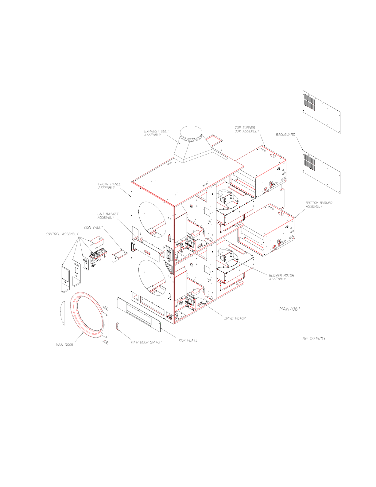
Quick Reference Diagram
For Detailed Information See The Table Of Contents On Next Page.
Page 4

Table of Contents
Front Panel Assembly ............................................................................................................................. 3
Right Coin Computer Panel Type II......................................................................................................... 4
Left Coin Computer Panel Type II .......................................................................................................... 5
Coin Chute Assembly ............................................................................................................................. 6
Coin Box/Vault Assembly (Left and Right) ............................................................................................... 7
Main Door Steel Assembly .............................................................................................................. 8, 9
Main Door Switch Assembly ................................................................................................................. 10
Basket (Tumbler)/Support Assemblies ................................................................................................... 11
Top Locking Lint Basket Assembly ....................................................................................................... 12
Bottom Locking Lint Basket Assembly .................................................................................................. 13
Separator Assembly .............................................................................................................................. 14
Rotational Sensor/Sail Switch and Teflon
Lint Coop and Adjustment Wheel Bracket Assembly ............................................................................. 16
Left Rear Wheel Bracket (3-Bolt) ......................................................................................................... 17
Right Rear Wheel Bracket (3-Bolt) ....................................................................................................... 18
Microprocessor Temperature Sensor Bracket Assembly ........................................................................ 19
Top Burner Box Assembly .............................................................................................................. 20, 21
Bottom Burner Box Assembly ......................................................................................................... 22, 23
Blower Motor Assembly ....................................................................................................................... 24
Rear Electrical Panel ............................................................................................................................. 25
Drive Motor/Motor Mount Assemblies .................................................................................................. 26
Exhaust Duct Assembly ......................................................................................................................... 27
Rear Back Guard Assembly .................................................................................................................. 28
®
Backup Washer Plate ........................................................... 15
Wrapper Gasket ................................................................................................................................... 29
Page 5
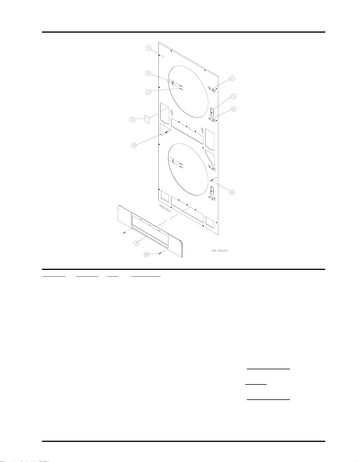
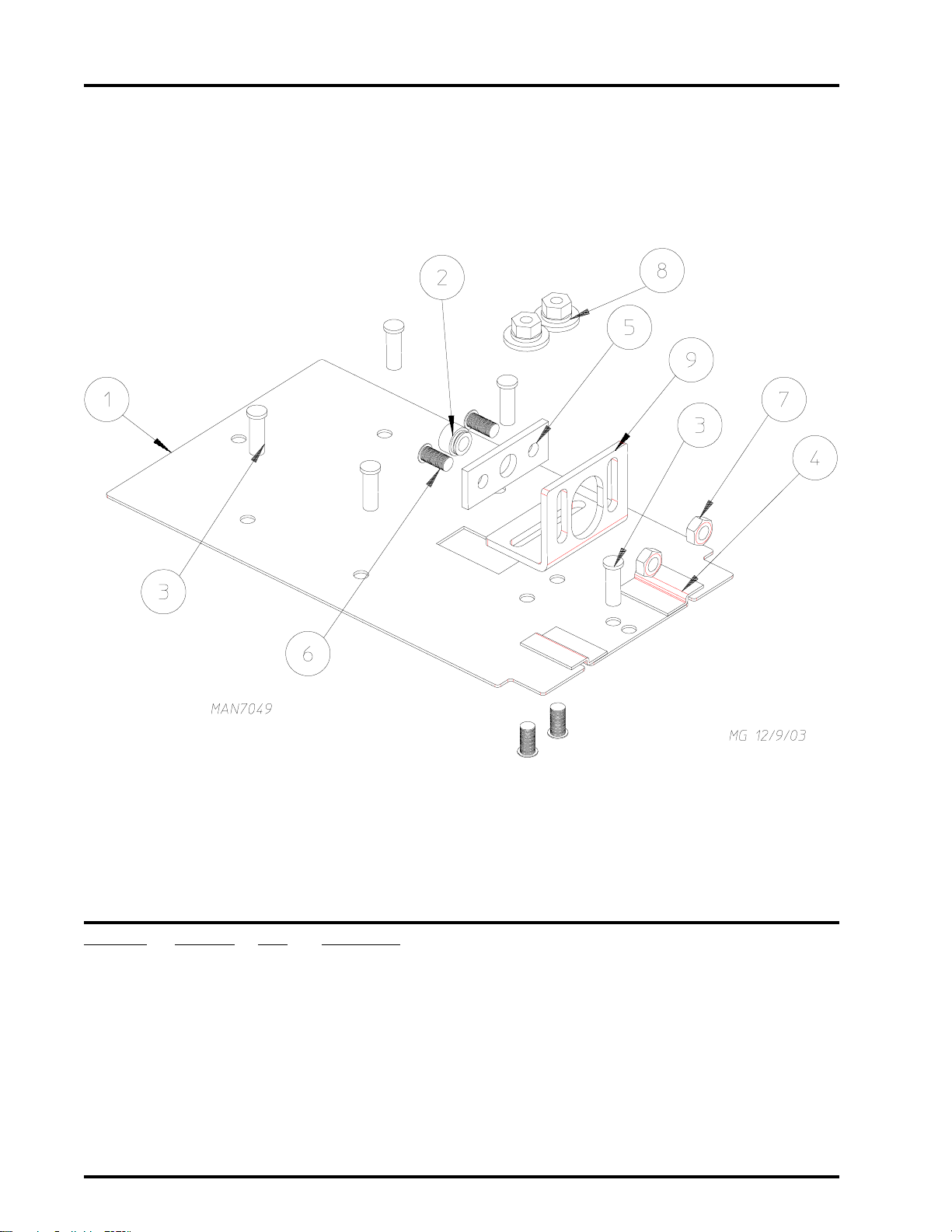
Coin Front Panel Assembly
3
Illus. No. Part No. Qty. Description
1 884117 1 White Right Hand Coin Front Panel Assembly
(includes illus. nos. 1, 2, 3, and 7)
884118 1 Bisque Right Hand Coin Front Panel Assembly
(includes illus. nos. 1, 2, 3, and 7)
884119 1 Stainless Steel Right Hand Coin Front Panel Assembly
(includes illus. nos. 1, 2, 3, and 7)
2 881987 2 Friction Door Latch Kit
(includes illus. nos. 2 and 3)
3 154215 4 5/32 x 1/4 Rivet
4 -------- 1 Top Hinge Block Assembly
(refer to Main Door Steel Assembly on page 12 and 13)
5 -------- 1 Main Door Switch
(refer to Main Door Switch Assembly on page 14)
6 -------- 1 Bottom Hinge Block Assembly
(refer to Main Door Steel Assembly on page 12 and 13)
7 354267 2 Arrow Backup Plate
8 150517 10 #10-16 x 1-1/2 Hex Head TEK Screw
9 882798 1 Black Kick Plate
10 150311 2 #10-16 x 3/4 Hex Head TEK Crimptite Screw
11 150309 8 #10-16 x 1/2 Hex Head TEK Crimptite Screw
Telephone: (508) 678-9000 Fax: (508) 678-9447
Page 6
4
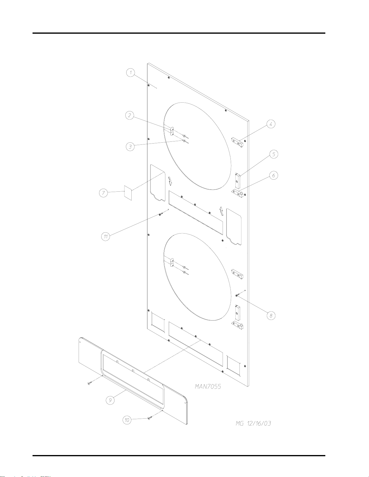
Non-Coin Front Panel Assembly
American Dryer Corporation 88 Currant Road / Fall River, MA 02720-4781
Page 7

Non-Coin Front Panel Assembly
Illus. No. Part No. Qty. Description
1 884120 1 White Right Hand Front Panel Assembly
(includes illus. nos. 1, 2, 3, and 7)
884121 1 Bisque Right Hand Front Panel Assembly
(includes illus. nos. 1, 2, 3, and 7)
2 881987 2 Friction Door Latch Kit
(includes illus. nos. 2 and 3)
3 154215 4 5/32 x 1/4 Rivet
4 -------- 1 Top Hinge Block Assembly
(refer to Main Door Steel Assembly on
5 -------- 1 Main Door Switch
(refer to Main Door Switch Assembly on page 14)
6 -------- 1 Bottom Hinge Block Assembly
(refer to Main Door Steel Assembly on page 12 and 13)
7 354267 2 Arrow Backup Plate
8 150517 10 #10-16 x 1-1/2 Hex Head TEK Screw
9 882798 1 Black Kick Plate
10 150311 2 #10-16 x 3/4 Hex Head TEK Crimptite Screw
11 150309 8 #10-16 x 1/2 Hex Head TEK Crimptite Screw
5
page 12 and 13)
Telephone: (508) 678-9000 Fax: (508) 678-9447
Page 8
6
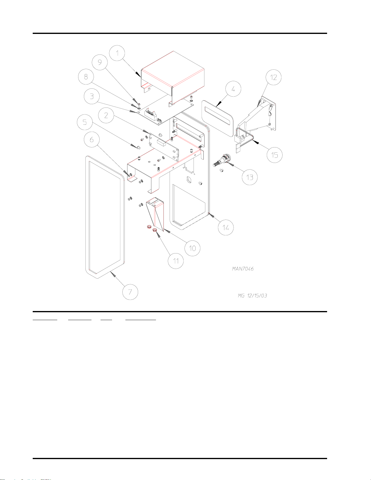
Right Coin Computer Panel Assembly
Illus. No. Part No. Qty. Description
1 354293 1 Computer Cover
2 137270 1 16 x 1 Large Character Display
3 887007 1 Phase 7 Coin Board (prior to February 1, 2004)
887011 1 Phase 7 Coin Board (as of February 1, 2004)
4 112575 1 Phase 7 Keypad
5 150201 4 #10-32 x 1/4 Phillips Pan Head Tap Screw
6 152102 4 M3 Metric Hex Nut
7 117603 1 1/8 x 9/16 Noise Suppressor Tape
8 153010 8 #6 Internal/External Star Washer
9 150005 4 #6-32 x 1/4 Phillips Round Head Machine Screw
10 354192 1 Optic Switch Protector
11 151001 2 #8-32 Pal Nut
12 852317 1 Phase 7 25¢ Coin Acceptor Assembly
13 182621 1 Control Panel Lock Assembly
14 860078 1 Phase 7 Coin Control Panel (panel only)
15 883774 1 Hanke Phase 7 Optic Switch Assembly
American Dryer Corporation 88 Currant Road / Fall River, MA 02720-4781
Page 9
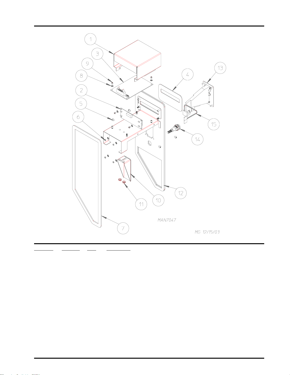
Left Coin Computer Panel Assembly
7
Illus. No. Part No. Qty. Description
1 354293 1 Computer Cover
2 137270 1 16 x 1 Large Character Display
3 887007 1 Phase 7 Coin Board (prior to February 1, 2004)
887011 1 Phase 7 Coin Board (as of February 1, 2004)
4 112575 1 Phase 7 Keypad
5 150201 4 #10-32 x 1/4 Phillips Pan Head Tap Screw
6 152102 4 M3 Metric Hex Nut
7 117603 1 1/8 x 9/16 Noise Suppressor Tape
8 153010 1 #6 Internal/External Star Washer
9 150005 4 #6-32 x 1/4 Phillips Round Head Machine Screw
10 354192 1 Optic Switch Protector
11 151001 2 #8-32 Pal Nut
12 860080 1 Phase 7 Coin Control Panel (panel only)
13 852317 1 Phase 7 25¢ Coin Acceptor Assembly
14 182621 1 Control Panel Lock Assembly
15 883774 1 Hanke Phase 7 Optic Switch Assembly
Telephone: (508) 678-9000 Fax: (508) 678-9447
Page 10
8
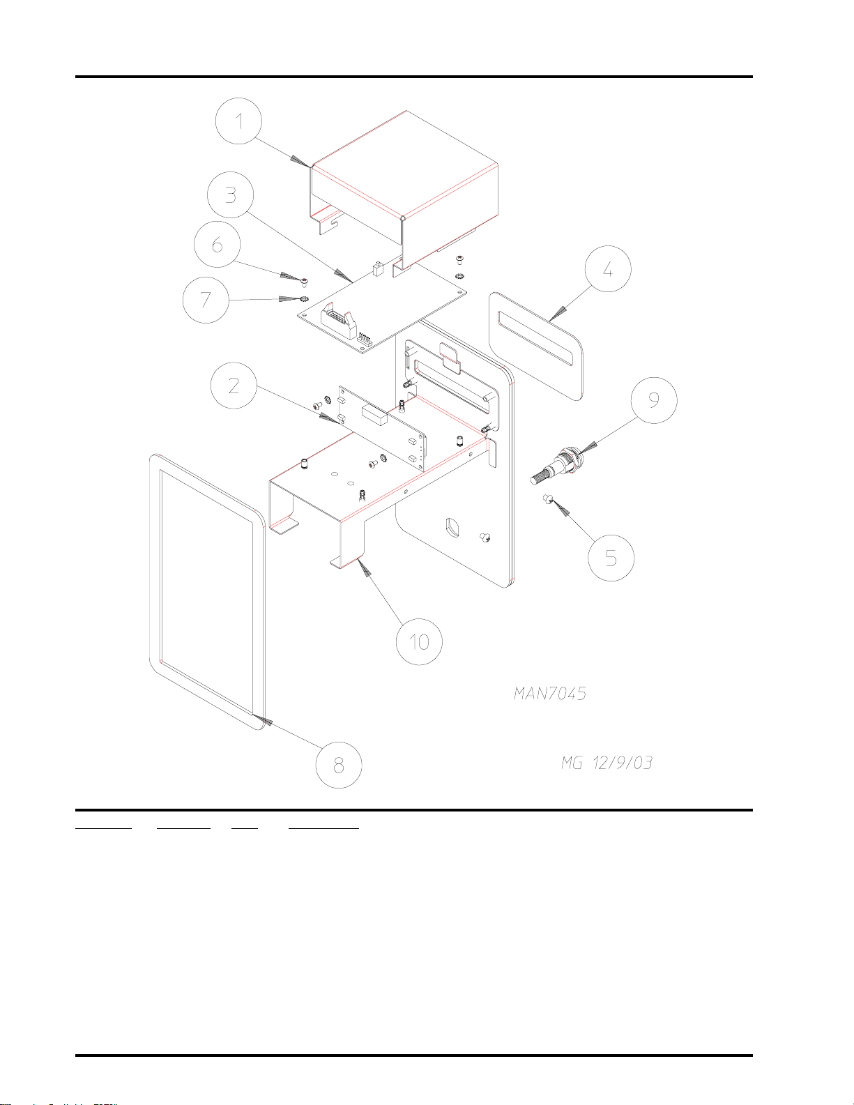
Non-Coin Computer Panel Assembly
Illus. No. Part No. Qty. Description
1 354293 1 Computer Cover
2 137270 2 16 x 1 Large Character Display
3 887007 1 Phase 7 Coin Board (prior to February 1, 2004)
887011 1 Phase 7 Coin Board (as of February 1, 2004)
4 112575 1 Phase 7 Keypad
5 150201 4 #10-32 x 1/4 Phillips Pan Head Tap Screw
6 150005 4 #6-32 x 1/4 Phillips Round Head Machine Screw
7 153010 4 #6 Internal/External Star Washer
8 117603 1 1/8 x 9/16 Noise Suppressor Tape
9 182621 1 Control Panel Lock Assembly
10 860096 1 Phase 7.3 Non-Coin Computer Panel
American Dryer Corporation 88 Currant Road / Fall River, MA 02720-4781
Page 11
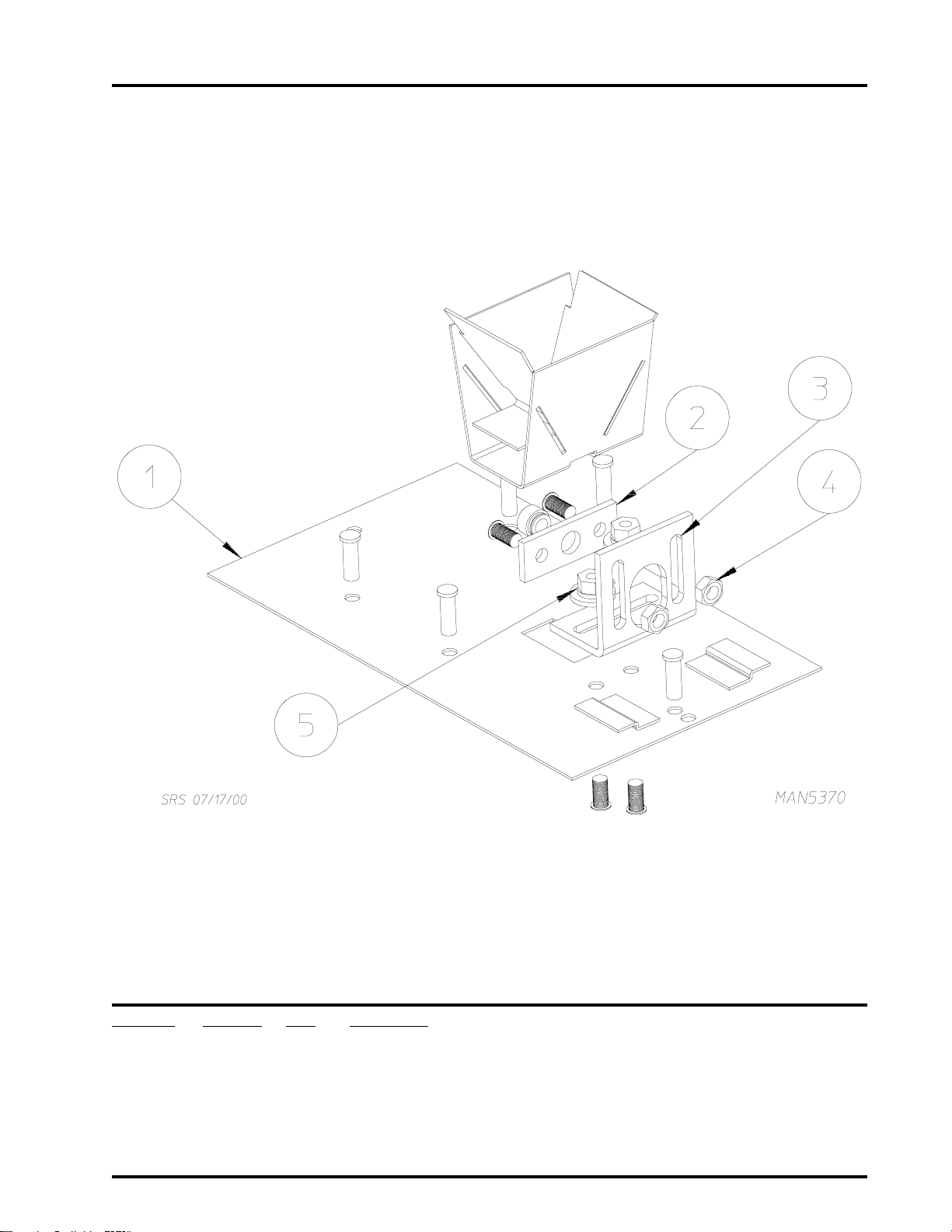
Coin Chute Assembly
9
Illus. No. Part No. Qty. Description
1 884113 1 Coin Chute Assembly Complete
(includes illus. nos. 1 through 5)
2 882937 1 Control Panel Lock Plate
3 354046 1 Easy Card Lock Bracket
4 152002 2 1/4-20 Hex Nut
5 152014 2 1/4-20 Free Spin Wash Nut
Telephone: (508) 678-9000 Fax: (508) 678-9447
Page 12
10
Easy Debit Card Coin Chute Assembly
Illus. No. Part No. Qty. Description
1 354114 1 Coin Chute Plate
2 153599 1 5/16-18 Clinch Nut
3 153557 5 1/4" x 3/4" Clinch Stud
4 354176 2 Control Panel Slide Clip
5 354181 1 Control Panel Lock Plate
6 153526 4 1/4" x 1/2" Clinch Stud
7 152002 2 1/4-20 Hex Nut
8 152014 2 1/4-20 Free Spin Wash Nut
9 354046 1 Easy Card Lock Bracket
884124 1 Easy Debit Card Coin Chute Assembly
American Dryer Corporation 88 Currant Road / Fall River, MA 02720-4781
Page 13

Coin Box/Vault Assembly (Left and Right)
11
Illus. No. Part No. Qty. Description
1 882740 1 Black Left/Right Coin Box Face Plate ONLY
882745 1 Left Coin Box with Black Face Plate (less lock)
2 882672 1 Coin Box Lock Kit (includes 2 locks keyed alike)
3 160136* 1 Coin Box Lock Key ONLY
4 882742 1 Black Left Coin Vault ONLY
5 882740 1 Black Left/Right Coin Box Face Plate ONLY
882746 1 Right Coin Box with Black Face Plate (less lock)
6 882741 1 Black Right Coin Vault ONLY
* Specify key number when ordering.
Telephone: (508) 678-9000 Fax: (508) 678-9447
Page 14

12
Main Door Steel Assembly
American Dryer Corporation 88 Currant Road / Fall River, MA 02720-4781
Page 15

Main Door Steel Assembly
Illus. No. Part No. Qty. Description
1 881150 1 Black Main Door Assembly Complete
(includes illus. nos. 1, 2, and 8 through 15)
881207 1 Stainless Steel Main Door Assembly Complete
(includes illus. nos. 1, 2, and 8 through 15)
2 102354 1 Door Gasket
170730 1 Clear Glass Adhesive (10.3 oz. cartridge)
170731 Black Glass Adhesive (10.3 oz. cartridge)
3 881152 1 Black Top Hinge Block Assembly
(includes illus. nos. 3 and 4)
881208 1 Stainless Steel Top Hinge Block Assembly
4 150445 2 1/4-20 x 3/4 Black Cap Head Setscrew
5 153031 1 1/4 Nylon Washer
6 881151 1 Black Bottom Hinge Block Assembly
(includes illus. nos. 5, 6, and 7)
881209 1 Stainless Steel Bottom Hinge Block Assembly
7 150445 2 1/4-20 x 3/4 Black Cap Head Setscrew
150443 2 1/4-20 x 3/4 Stainless Steel Cap Head Setscrew
8 150683 3 1/4-20 x 5/8 Black Carriage Bolt
150682 3 1/4-20 x 5/8 Stainless Steel Carriage Bolt
(for models with stainless steel doors)
9 152014 3 1/4-20 Free Spin Wash Nut
10 151010 1 #10-32 Black Hex Acorn Nut
151009 1 #10-32 Stainless Steel Hex Acorn Nut
11 150120 1 Door Latch Screw
12 150683 3 1/4-20 x 5/8 Black Carriage Bolt
150682 3 1/4-20 x 5/8 Stainless Steel Carriage Bolt
(for models with stainless steel doors)
13 152014 3 1/4-20 Free Spin Wash Nut
14 881210 1 Black Main Door Handle ONLY
170333 1 Stainless Steel Main Handle ONLY
15 102211 1 Door Glass
13
Telephone: (508) 678-9000 Fax: (508) 678-9447
Page 16

14
Main Door Switch Assembly
Illus. No. Part No. Qty. Description
1 153566 2 #6-32 x 7/8 Clinch Stud
2 152013 2 #6-32 Hex Nut
3 153010 2 #6 Internal/External Star Washer
4 137005 1 Door Switch
5 122636 2 Flag Terminal
6 881211 1 Black Main Door Switch Housing ONLY
353209 1 Stainless Steel Main Door Switch Housing ONLY
881153 1 Black Main Door Switch Housing Complete
(includes illus. nos. 1, 2, 3, 4, and 6)
800474 1 Stainless Steel Main Door Switch Housing Complete
(includes illus. nos. 1, 2, 3, 4, and 6)
7 150301 2 #8-18 x 7/16 Phillips Pan Head TEK Screw
American Dryer Corporation 88 Currant Road / Fall River, MA 02720-4781
Page 17

Basket (Tumbler)/Support Assemblies
15
Illus. No. Part No. Qty. Description
1 154210 40 5/32 x 3/16 Pop Rivet
2 354217 1 Spacer Plate
3 153048 1 Inner Friction Teflon® Pad
4 116332 1 94 x 2-1/2 x 1/8 Felt Collar
5 882765 1 One Arm Basket (tumbler) Support Assembly
(includes illus. nos. 2, 3, and 5)
6 882766 1 Basket (tumbler) Assembly For One Arm Basket (tumbler) Support
(includes illus. nos. 1, 4, and 9)
882990 1 One Arm Basket (tumbler) and Support Assembly Complete
(includes illus. nos. 1 through 7 and 9)
7 154210 6 5/32 x 3/16 Pop Rivet
8 100191 1 12 Rib 105 Long (J) High Temperature Belt
9 115907 1 Inner Ring Felt Collar
401010 1 #847 Adhesive For Felt Collar (5 oz. tube)
Telephone: (508) 678-9000 Fax: (508) 678-9447
Page 18

16
Top Locking Lint Basket Assembly
Illus. No. Part No. Qty. Description
1 115904 1 Lint Basket Felt
2 154210 5 5/32 x 3/16 Pop Rivet
3 160140 1 Key ONLY For XX4451
4 160066 1 1/16" Offset x 1-1/8" Long Cam
5 117605 4 1/4 x 3/8 Neoprene Sponge Tape (sold by the foot)
6 882787 1 Top Locking Lint Basket with Lock (white)
(includes illus. nos. 1 through 7)
7 160038 1 Lint Basket Lock with Cam (no key)
160050 1 Lint Basket Lock (no cam and key) For Stainless Steel ONLY
American Dryer Corporation 88 Currant Road / Fall River, MA 02720-4781
Page 19

Bottom Locking Lint Basket Assembly
17
Illus. No. Part No. Qty. Description
1 115904 1 Lint Basket Felt
2 154210 5 5/32 x 3/16 Pop Rivet
3 160140 1 Key ONLY For XX4451
4 160066 1 1/16" Offset x 1-1/8" Long Cam
5 117604 4 1/8 x 3/8 Neoprene Sponge Tape (sold by the foot)
6 882797 1 Bottom Locking Lint Basket Assembly with Lock (black)
(includes illus. nos. 1 through 7)
7 160038 1 Lint Basket Lock with Cam (no key)
Telephone: (508) 678-9000 Fax: (508) 678-9447
Page 20

18
Top Lint Basket Assembly
Illus. No. Part No. Qty. Description
1 115904 1 Lint Basket Felt
2 154210 5 5/32 x 3/16 Pop Rivet
3 117604 4 1/4 x 3/8 Neoprene Sponge Tape (sold by the foot)
4 884123 1 White Lint Basket Assembly (includes illus. nos. 1 through 4)
American Dryer Corporation 88 Currant Road / Fall River, MA 02720-4781
Page 21

Bottom Lint Basket Assembly
19
Illus. No. Part No. Qty. Description
1 115904 1 Lint Basket Felt
2 154210 5 5/32 x 3/16 Pop Rivet
3 117605 4 1/4 x 3/8 Neoprene Sponge Tape (sold by the foot)
4 884122 1 Black Lint Basket Assembly (includes illus. nos. 1 through 4)
Telephone: (508) 678-9000 Fax: (508) 678-9447
Page 22

20
Separator Assembly
Illus. No. Part No. Qty. Description
1 152014 18 1/4-20 Free Spin Wash Nut
2 882926 1 Inner Ring Separator Bracket
882717 1 Inner Ring Separator Assembly
(includes illus. nos. 1 through 3)
3 115903 1 Basket (tumbler) Separation Felt
American Dryer Corporation 88 Currant Road / Fall River, MA 02720-4781
Page 23

Rotational Sensor/Sail Switch and Teflon® Backup Washer Plate
21
Illus. No. Part No. Qty. Description
1 353283 1 Rotational Sensor Bracket
2 319202 1 Sail Switch Flat Damper
3 154004 1 Tinnerman Twin Speed Nut
4 154002 1 1/8 Push On Fastener
5 153528 1 8/32 x 1/2 Self-Clinching Stud
6 152014 2 1/4-20 Free Spin Wash Nut
7 150303 2 Phillips Pan Head Screw
8 122200 1 Sail Switch
9 105550 1 Sail Switch Rod
883934 1 Teflon® Backup Washer and Magnet Assembly
(includes illus. nos. 10 through 12, 17, and 18)
10 353282 1 Thrust Bearing Backup Washer
11 353281 1 Backup Washer Rivet Spacer
12 154218 1 1/8 Diameter Aluminum Rivet
13 153053 1 5/16 Lock Washer
14 150640 1 5/16-18 X 7/8 Hex Bolt
15 354217 1 Plate Spacer
16 153048 1 Inner Friction Pad
17 153047 1 Outer Teflon® Friction Pad
18 102102 1 1 x 3/4 x 0.197 Door Magnet
19 822735 1 Phase 7 Rotational Sensor Switch
Telephone: (508) 678-9000 Fax: (508) 678-9447
Page 24

22
Lint Coop and Adjustment Wheel Bracket Assembly
Illus. No. Part No. Qty. Description
1 354067 1 Thrust Wheel Mount
2 150682 4 1/4-20 x 5/8 Stainless Steel Carriage Bolt
3 154284 2 Basket (tumbler) Wheel Spacer
4 154267 2 M10 x 25 mm Shoulder Screw
5 154013 2 M8 Hex Nut
6 153002 2 5/16 Split Lock Washer
7 180032 2 Duratred Idler Wheel
8 122002 1 Arcolectric Door Switch
9 150309 2 #10-16 x 1/2 Hex Head TEK Crimptite Screw
10 354156 1 Lint Switch Bracket
11 152014 6 1/4-20 Free Spin Wash Nut
12 154210 20 5/32 x 3/16 Pop Rivet
13 854029 1 Lint Coop
14 152001 2 #8-32 x 3/8 Hex Nut
15 354171 1 Harness Stiffener
American Dryer Corporation 88 Currant Road / Fall River, MA 02720-4781
Page 25

Left Rear Wheel Bracket (3-Bolt)
23
Illus. No. Part No. Qty. Description
1 150220 1 3/8-24 Hex Nut
2 150510 3 1/4-20 x 3/4 Hex Head Machine Bolt
3 153007 3 1/4 Split Lock Washer
4 883004 1 Left Rear Roller Wheel Bracket ONLY (3-bolt)
883125 1 Left Rear Roller Wheel Bracket Assembly with Hardware (3-bolt)
5 883101 1 Thruster Wheel
Telephone: (508) 678-9000 Fax: (508) 678-9447
Page 26

24
Right Rear Wheel Bracket (3-Bolt)
Illus. No. Part No. Qty. Description
1 883005 1 Right Rear Roller Wheel Bracket ONLY (3-bolt)
883126 1 Right Rear Roller Wheel Bracket Assembly with Hardware (3-bolt)
2 150220 1 3/8-24 Hex Nut
3 150510 3 1/4-20 x 3/4 Hex Head Machine Bolt
4 153007 3 1/4 Split Lock Washer
5 883101 1 Thruster Wheel
American Dryer Corporation 88 Currant Road / Fall River, MA 02720-4781
Page 27

Microprocessor Temperature Sensor Bracket Assembly
25
Illus. No. Part No. Qty. Description
1 882682 1 Temperature Sensor Bracket Assembly Complete
(includes illus. nos. 1 through 6, 8, and 12 through 14)
354117 1 Sensor Bracket ONLY
2 152013 2 #6-32 Hex Nut
3 153010 2 #6 Star Washer
4 150005 2 #6-32 x 1/4 Phillips Round Head Machine Screw
5 883025 1 Microprocessor Temperature Sensor Probe Assembly
(includes illus. nos. 5, 6, and 12 through 14)
6 154007 2 1/4 Push On Fastener
7 152014 2 1/4-20 Free Spin Wash Nut
8 130119 1 Temperature Sensor
9 121494 2 3/16 Push Mount Wire Tie
10 122700 4 Pin Terminal ONLY
11 122604 1 4-Position Connectors (male)
12 121028 2 1/4 Push On Terminal
13 122701 4 Socket Terminal ONLY
122801 Pin/Socket Extraction ToolNot Illustrated
14 122605 1 4-Position Connectors (female)
Telephone: (508) 678-9000 Fax: (508) 678-9447
Page 28

26
Top Burner Box Assembly
American Dryer Corporation 88 Currant Road / Fall River, MA 02720-4781
Page 29

Top Burner Box Assembly
Illus. No. Part No. Qty. Description
1 141138 1 Two Port Burner Manifold
2 128927 1 1/2 24 VAC (natural gas) Gas Valve
3 142710 1 3/4 x 4 Black Nipple
4 354146 2 Bottom Burner Baffle
5 150512 2 1/4-20 x 1/2" Hex Head Machine Bolt
6 130400 1 Temperature Sensor
7 354162 1 Direct Spark Ignition (DSI) Module Mounting Panel
8 354163 1 Pipe Bracket
9 142505 1 3/4 x 1/2 x 1/2 Tee
10 142700 1 1/2 Close Nipple
11 801048 1 Direct Spark Ignition (DSI) Johnson Control
12 121300 1 Open/Closed Bushing
13 128915 1 Ignition with Flame Probe
14 141137 2 Stainless Steel Burner Tube
15 150299 2 #10 x 1 Hex Washer TEK Screw
16 121400 1 7/8 Universal Bushing
17 128919 1 36 Ignition Cable
18 140844 2 Burner Orifice
19 354049 1 Gas Valve Mounting Bracket
20 354100 1 Manifold Support
21 354170 1 Burner Tube Hood
22 153018 2 1/4 Flat Washer
23 318700 1 Small Burner Tube Bracket
24 153562 2 #6-32 x 3/4 Black Self-Clinching Stud
25 152013 2 #6-32 Hex Nut
26 150309 31 #10-16 x 1/2 Hex Head TEK Crimptite Screw
27 120910 1 Green Ground Screw
28 152002 2 1/4-20 Hex Nut
29 153007 2 1/4 Split Lock Washer
30 142601 1 3/4 Black Union
31 860073 1 Phase 7 Burner Box
27
Telephone: (508) 678-9000 Fax: (508) 678-9447
Page 30

28
Bottom Burner Box Assembly
American Dryer Corporation 88 Currant Road / Fall River, MA 02720-4781
Page 31

Bottom Burner Box Assembly
Illus. No. Part No. Qty. Description
1 141138 1 Two Port Burner Manifold
2 141137 2 Stainless Steel Burner Tube
3 128927 1 1/2 24 VAC (natural gas) Gas Valve
4 143118 1 1/2 x 1/2 x 60 Stainless Steel Flex Hose
5 354146 2 Bottom Burner Baffle
6 128915 1 Ignition with Flame Probe
7 801048 1 Direct Spark Ignition (DSI) Johnson Control
8 354162 1 Direct Spark Ignition (DSI) Module Mounting Panel
9 142506 1 1/2 x 1/2 Street Elbow
10 318700 1 Small Burner Tube Bracket
11 130400 1 Temperature Sensor
12 128919 1 36 Ignition Cable
13 354170 1 Burner Tube Hood
14 354261 1 Flexible Gas Line Bracket
15 354100 1 Manifold Support
16 140844 2 Burner Orifice
17 354049 1 Gas Valve Mounting Bracket
18 150512 2 1/4-20 x 1/2" Hex Head Machine Bolt
19 121300 1 Open/Closed Bushing
20 121400 1 7/8 Universal Bushing
21 150299 2 #10 x 1 Hex Washer TEK Screw
22 153562 2 #6-32 x 3/4 Black Self-Clinching Stud
23 152013 2 #6-32 Hex Nut
24 150309 29 #10-16 x 1/2 Hex Head TEK Crimptite Screw
25 153007 2 1/4 Split Lock Washer
26 152002 2 1/4-20 Hex Nut
27 120910 1 Green Ground Screw
28 153018 4 1/4 Flat Washer
29 860073 1 Phase 7 Burner Box
29
Telephone: (508) 678-9000 Fax: (508) 678-9447
Page 32

30
Blower Motor Assembly
Illus. No. Part No. Qty. Description
1 181038 1 1/4 hp 115/230v/60 Hz Blower Motor
2 153050 4 1/2 x 1-1/16 Flat Washer
3 152006 2 1/2-20 Left Hand Jam Nut
4 100731 1 1/8 x 3/32 x 1-1/8 Key
5 153007 4 1/4 Split Lock Washer
6 153001 4 5/16 Flat Washer
7 153002 4 5/16 Split Lock Washer
8 152004 4 5/16-18 Hex Nut
9 154279 4 5/16-18 x 3/4 Carriage Bolt
10 117604 1 1/8 x 3/8 Neoprene Sponge Tape (sold by the foot)
11 150111 4 1/4-20 x 1/2 Phillips Round Head Machine Screw
12 884039 1 Blower Motor Mount ONLY
13 802029 1 12-1/2 Riveted Impellor with 1/2 Bore
884040 1 Blower Motor and Mount Assembly Complete
(includes illus. nos. 1 through 13)
American Dryer Corporation 88 Currant Road / Fall River, MA 02720-4781
Page 33

Rear Electrical Panel (Top and Bottom)
31
Illus. No. Part No. Qty. Description
1 860063 1 Transformer Assembly
2 151000 2 #6-32 Pal Nut
3 150002 2 #6-32 x 1 Phillips Round Head Screw
4 150103 2 #8-32 x 3/4 Phillips Round Head Machine Screw
5 120714 1 Quick Connect Power Block
6 132475 2 Double Pole 24v Contactor
7 150301 3 #8-18 x 7/16 Phillips Pan Head TEK Screw
8 112075 1 Ground Label
9 136008 1 Fuse Holder
10 114103 1 Electrical Service Label
11 121010 1 L-70 14-4 Terminal Lug
12 120910 1 Green Ground Screw
13 153021 2 1/4 External/Internal Shakeproof Washer
14 152002 2 1/4-20 Hex Nut
15 151001 2 #8-32 Pal Nut
16 120712 1 12 Position Block 250v 25A
17 136049 1 3/4-Amp (Slo-Blo) Fuse
18 824828 2 R.C. Network Assembly
Telephone: (508) 678-9000 Fax: (508) 678-9447
Page 34

32
Drive Motor/Motor Mount Assemblies
Illus. No. Part No. Qty. Description
1 354263 1 Sheave
2 154274 1 3/8-16 x 2-1/4 Long Spade Bolt
3 153001 4 5/16 Flat Washer
4 152004 4 5/16-18 Hex Nut
5 153002 4 5/16 Split Lock Washer
6 100250 1 Efson Back Side Idler Assembly
7 121350 1 13/32 x 3/8 I.D. Bronze Bushing
8 150600 1 3/8-16 x 1-1/2 Hex Head Tap Bolt
9 154266 1 5/16-18 x 3/8 x 3/8 Shoulder Screw
10 154276 1 1/4-20 x 1/4 x 5/8 Shoulder Bolt
11 152005 2 3/8-16 Hex Nut
12 150508 4 3/8-16 x 3/4 Hex Machine Bolt
13 153005 5 3/8 Split Lock Washer
14 153004 4 3/8 x 1 O.D. Flat Washer
15 154279 4 5/16-18 x 3/4 Carriage Bolt
16 157010 1 1-7/8 Extension Spring
17 181035 1 1/4 hp 115v 60 Hz Motor
18 854014 1 Idler Arm
19 854012 1 Motor Mount
20 154321 1 5/16-24 x 3/8 Allen Setscrew
American Dryer Corporation 88 Currant Road / Fall River, MA 02720-4781
Page 35

Exhaust Duct Assembly
33
Illus. No. Part No. Qty. Description
1 154200 8 5/32 Pop Rivet
2 860098 2 Blower Motor Assembly with Riveted Impellor
3 354171 2 Harness Stiffener
4 153018 8 1/4 Flat Washer
5 150510 8 1/4-20 x 3/4 Hex Head Machine Bolt
6 153007 8 1/4 Split Lock Washer
7 354078 2 Exhaust Access Plate
8 150309 12 #10-16 x 1/2 Hex Head TEK Screw
9 154210 43 5/32 x 3/16 Pop Rivet
10 854015 2 Air Plenum Assembly
11 854051 1 Lower Blower Housing
12 854049 1 Upper Blower Housing
13 151001 1 #8-32 Pal Nut
14 150103 4 #8-32 x 3/4 Phillips Round Head Machine Screw
Telephone: (508) 678-9000 Fax: (508) 678-9447
Page 36

34
Rear Back Guard Assembly
Illus. No. Part No. Qty. Description
1 103500 4 Leveling Leg
2 883070 2 Back Guard Short
3 150300 12 #10-16 x 1/2 TEK Screw
4 883071 1 Top Pocket Flex Gas Line Bracket
5 883160 1 Bottom Pocket Flex Gas Line Pivot Support
6 883073 1 Rear Right Side Panel Support Assembly
7 143118 1 1/2 x 1/2 x 60 Stainless Steel Flex Hose
American Dryer Corporation 88 Currant Road / Fall River, MA 02720-4781
Page 37

Wrapper Gasket
35
Illus. No. Part No. Qty. Description
1 102310 4 Wrapper Gasket (sold by the foot)
401010 1 3M Mastic
2 860045 1 Left Wrapper Assembly
3 860044 1 Right Wrapper Assembly
4 852319 1 Axial Sensor Probe Assembly
5 354243 1 Inner Back Cover Plate
6 360155 1 Left Side Air Blockage Plate
7 360153 1 Right Side Air Blockage Plate
Telephone: (508) 678-9000 Fax: (508) 678-9447
Page 38

ADC 450257 1- 02/10/04 - 0
 Loading...