

Tumble Dryer
AD-25V / AD-30V / AD-50V / AD-758V
EN – Installation/Operator Manual
GB, IE
To avoid errors and damage to the dryer,
please read these instructions carefully
before attempting to install or operate
American Dryer Corporation
88 Currant Road
Fall River MA 02720-4781 USA
Telephone: +1 (508) 678-9000 / Fax: +1 (508) 678-9447
e-mail: techsupport@amdry.com
www.adclaundry.com
ADC Part No. 113686-1
Safety Precautions ______________
Only qualified personnel should install, service,
or adjust this equipment.
The information in this manual must be followed to minimize
the risk of fire or explosion and to prevent property damage,
personal injury, or loss of life.
Do not allow children to play on or in the dryer.
Children must be supervised when near an operating dryer.
The appliance can be used by children aged
from 8 years and above and persons with
reduced physical, sensory and mental
capabilities or lack of experience and
knowledge if they have been given supervision
or instruction concerning use of appliance in a
safe way and understand the hazards involved.
Do not modify this appliance.
Do not bypass or disable any door or drawer switch.
Do not bypass or disable any heat safety circuit.
Do not operate with any guards or service panels removed.
Do not operate if the lint filter is not in place.
Do not use dryer in the presence of dry cleaning fumes.
Do not spray aerosols near the dryer while it is operating.
Dry only water washed fabrics. Do not dry articles spotted or
washed in dry cleaning solvents, combustible detergents,
industrial chemicals, or “all-purpose” cleaner.
Do not dry rags or articles coated or contaminated with gasoline,
kerosene, oil, paint, or wax.
Items that have been spotted or soaked with vegetable or
cooking oil constitute a fire hazard and should not be dried.
Do not dry mop heads. Contaminations from wax or flammable
solvents are a fire hazard.
Do not store or use gasoline or other flammable liquids or vapors
in the vicinity of this appliance.
A qualified technician must be called if any high-limit thermostat
trips to investigate, and resolve, the issue.
Disconnect power before resetting any safety device.
Do not use heat for drying articles that contain plastic, foam,
sponge rubber, or similarly textured rubber materials.
Lint buildup in the burner area, exhaust duct, and around the
machine is a fire hazard and must be cleaned frequently.
You must disconnect and lockout the electric supply and the
gas supply, before removing any guards.
Label all wires prior to disconnection when servicing the dryer.
Every drying cycle finishes with a cool-down period to remove
heat from the dry load. Never stop the dryer before the end of
the drying cycle unless the load is quickly removed and spread
out to allow the heat to dissipate quickly.
Fabric softeners or similar products should only be used as
recommended by the fabric softener manufacturer.
Exhaust duct outlet should be checked periodically for
blockages, and if any found, removed.
Use this dryer only for its intended purpose, drying fabrics.
Purchaser and user should consult the local gas supplier for
proper instructions to be followed in the event the user smells
gas. The instructions should be posted in a prominent location.
What To Do If You Smell Gas:
• Do not try to operate any appliance.
• Do not touch any electrical switch.
• Do not use any phone in your building.
• Clear the room, building, and area of all occupants.
• Immediately call your gas supplier from a neighbor’s
phone. Follow the gas supplier’s instructions.
• If you cannot reach your gas supplier, call the fire
department.
Table of Contents ________________________________________________________________________
SAFETY PRECAUTIONS ........................................................................................................................ 2
TECHNICAL SPECIFICATIONS .............................................................................................................. 4
INSTALLATION PROCEDURES ............................................................................................................. 6
LOCATION REQUIREMENTS ................................................................................................................. 6
UNPACKING / SETTING UP ................................................................................................................... 6
DRYER ENCLOSURE REQUIREMENTS .............................................................................................. 6
FRESH (MAKE-UP) AIR SUPPLY REQUIREMENTS ............................................................................ 6
EXHAUST REQUIREMENTS .................................................................................................................. 6
ELECTRICAL INFORMATION (50HZ) .................................................................................................... 8
GAS INFORMATION.............................................................................................................................. 10
GAS TYPE CONVERSION .....................................................................................................................11
BURNER PRESSURE MEASURE AND ADJUST ................................................................................ 12
STEAM INFORMATION......................................................................................................................... 12
WATER INFORMATION ........................................................................................................................ 14
START-UP .............................................................................................................................................. 14
PREOPERATIONAL TEST .................................................................................................................... 14
OPERATING INSTRUCTIONS.............................................................................................................. 14
ROUTINE MAINTENANCE.................................................................................................................... 15
SERVICE / PARTS INFORMATION ...................................................................................................... 15
DATA LABEL INFORMATION ................................................................................................................ 15
WARRANTY INFORMATION ................................................................................................................ 16
2 American Dryer Corp. 113686-1

This Page Is
Intentionally Left Blank
113686-1 www.adclaundry.com 3
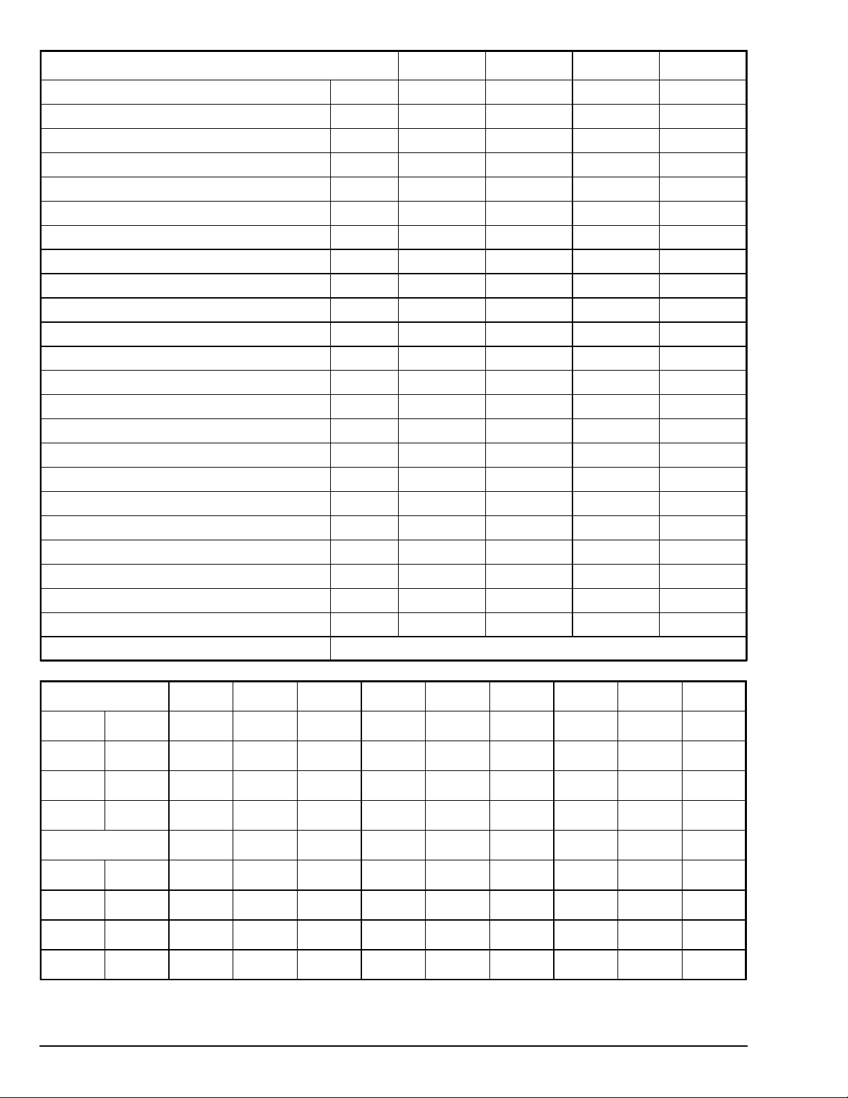
Technical Specifications AD-25V AD-30V AD-50V AD-758V
Maximum Capacity (Dry Weight) kg
Tumbler Volume liters
Tumbler (Diameter x Depth) cm
Door Opening (Diameter) cm
Airflow (50Hz) (Gas-Electric / Steam) cmm
Heat Rate (Gas) kW
Heat Rate (Steam) – Normal Load Bhp
Steam Consumption kg/hr
Airborne Sound Level dB(A)
Tumbler (Drive) Motor (Non Reversing / Reversing) kW
Blower (Fan) Motor (Non Reversing / Reversing) kW
Net Weight (Approximate) (Gas-Electric / Steam) kg
Shipping Weight (Approximate) (Gas-Electric / Steam) kg
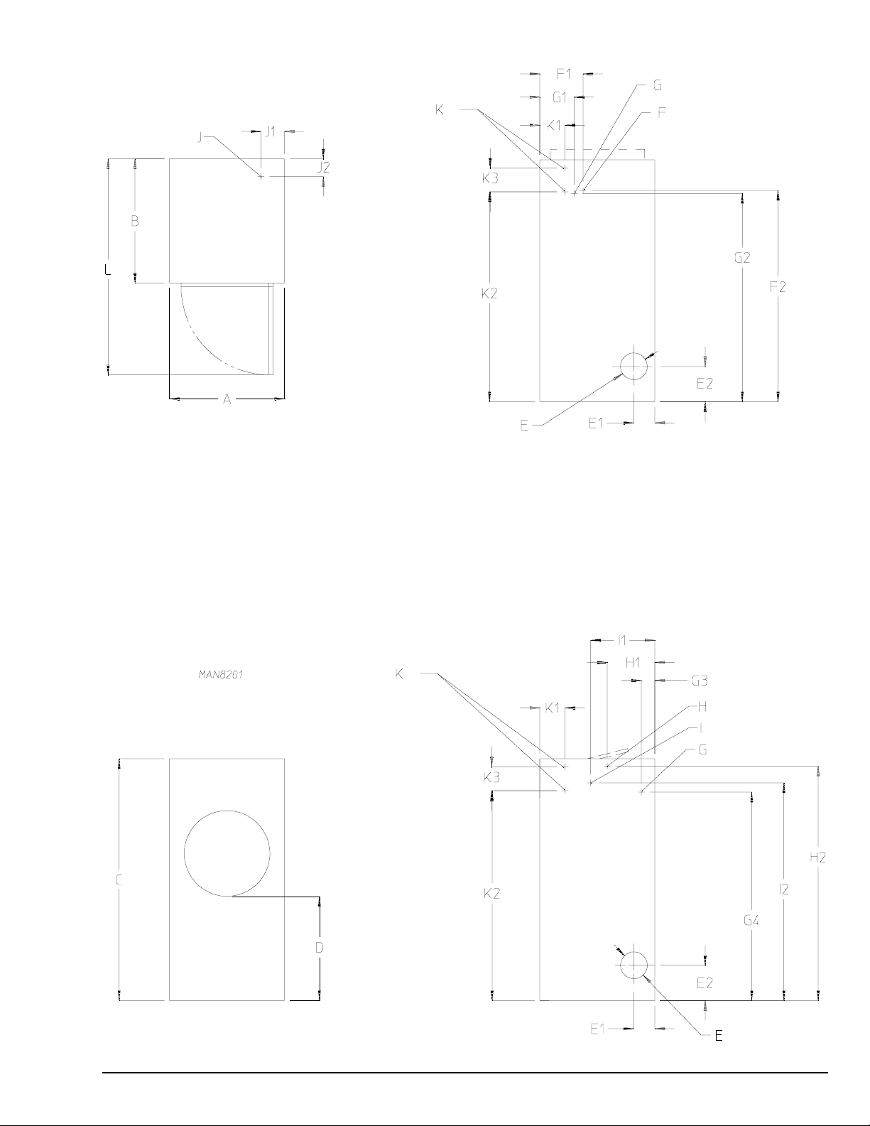
Cabinet Width (A) cm
Cabinet Depth (B) cm
Cabinet Height (C) (+8 cm for Electric) cm
Door Sill Height (D) cm
11.3 13.6 22.7 34.0
262 354 518 609
83.2 x 48.3 83.2 x 65.1 83.2 x 95.3 92.1 x 91.4
54.6 54.6 54.6 79.7
10.9 / 10.9 10.9 / 10.9 17.7 / 17.7 23.6 / 28.3
22.9 27.8 44.0 51.3
2.9 3.0 4.1 7.2
44.8 47.2 64.4 124.7
<70 <70 <70 <70
0.37 / 0.37 0.37 / 0.37 0.56 / 0.37 0.75 / 0.37
— / 0.37 — / 0.37 — / 0.37 — / 0.75
185 / 197 235 / 262 295 / 310 327 / 370
202 / 215 250 / 278 318 / 332 351 / 394
87.0 87.0 87.0 97.2
72.7 93.7 123.2 119.4
182.9 182.9 182.9 190.8
84.2 84.2 84.2 71.1
Exhaust Connection (Diameter) (E) cm
Gas Connection (F) ISO 7/1
Water Connection (G) ISO 7/1
Steam Supply Connection (H) FNPT
Steam Return Connection (I) FNPT
Air Connection – Pneumatic Damper - Steam (J) FNPT
Electric Connection (Gas / Steam Heat) (K)
E1 E2 F1 F2 G1 G2 G3 G4 H1
25V cm
30V cm
50V cm
758V cm
25V cm
30V cm
15.9 26.7 35.6 160.0 29.5 157.5 10.2 157.5 19.4
15.9 26.7 32.7 159.7 26.0 157.5 10.2 157.5 36.0
15.9 26.7 30.5 160.7 23.5 157.5 10.2 157.5 32.5
20.3 47.6 36.2 164.5 30.5 162.6 10.8 162.6 37.6
H2 I1 I2 J1 J2 K1 K2 K3 L
175.6 27.9 163.0 17.8 13.3 19.1 158.8 7.0 142.2
177.2 48.6 164.5 17.8 13.3 19.1 158.8 7.0 163.2
20.3 20.3 20.3 20.3
Rc 1/2Rc 1/2Rc 1/2Rc 3/4
R 3/4 R 3/4 R 3/4 R 3/4
1111
1111
1/8 1/8 1/8 1/8
50V cm
758V cm
177.2 44.8 164.5 17.8 13.3 19.1 158.8 7.0 192.4
180.5 51.8 171.5 17.8 13.3 19.1 163.8 7.0 215.9
NOTE: The manufacturer reserves the right to make changes in specifications at any time, without notice or obligation.
4 American Dryer Corp. 113686-1
113686-1 www.adclaundry.com 5

Installation Procedures __________________
Location Requirements
The temperature of the installation location must remain
between 4° C and 55° C.
The dryer must not be installed or stored in an area where it
will be exposed to water and/or weather.
The dryer should be located where a minimum amount of
exhaust ducting will be necessary.
The dryer must be installed on a sound level floor capable of
supporting its weight. Any carpeting must be removed.
Install a lockable door to prevent the public from accessing the
rear of the dryer.
The appliance must not be installed behind a lockable door, a
sliding door or a door with a hinge on the opposite side to that
of the tumble dryer, in such a way that a full opening of the
tumble dryer door is restricted.
Unpacking / Setting Up
Dryer must be handled in an upright position at all times.
Remove protective shipping material (i.e. plastic wrap and
optional shipping box) from the dryer.
Remove the pallet. Remove the 4 bolts securing the base of
the dryer to the pallet (one in each corner of the cabinet base).
Remove the back guard for access to the 2 rear bolts. Remove
the lint door or drawer to reach the 2 front bolts.
If the dryer is to be slid into its final position, ensure that all four
leveling legs (one in each corner) are extended slightly so the
dryer will slide on these legs (not the cabinet frame).
Once the dryer is in position, adjust the leveling legs so it is
level side-to-side. To increase bearing life and improve
efficiency, the dryer should be tilted slightly to the rear.
Dryer Enclosure Requirements
Clearance to combustible material
A Minimum 30 cm (46 cm recommended)
B Minimum 30 cm (61 cm recommended)
C Minimum 5 cm
D Minimum 10 cm
E Maximum 10 cm
Clearance to nearest obstacle
F Open Door:
AD-25V, AD-30V, AD-50V: 76 cm, AD-758V: 102 cm
G 2.5 cm (To allow control door to open)
H 2.5 cm
I 1.5 mm
J 1.5 mm
Fresh (Make-Up) Air Supply
Requirements
The dryer draws in air, heats it, passes it through
the tumbler, and exhausts it outside.
Adequate ventilation has to be provided to avoid the back flow
of gases into the room from appliances burning fuels, including
open fires.
Insufficient fresh air supply could diminish dryer performance.
Make-up air must be free of dry cleaning solvent fumes.
Locate fresh air openings away from exhaust vent discharge.
Locate the openings behind the dryer to avoid room drafts.
2
An unrestricted opening to the outdoors of 500 cm
AD-25V, 610 cm2 for each AD-30V, 970 cm2 for each AD-50V
and 1,130 cm2 for each AD-758V is required (Based on 22 cm
per kW).
Separate make-up air openings are not required. Common
openings, located evenly between the dryers, are acceptable.
The size of the make-up air opening must be increased by
33% to compensate for the use of registers or louvers.
for each
Exhaust Requirements
Single (independent) dryer venting is recommended.
Dryers must be exhausted to the outdoors.
The dryer shall not be exhausted into any gas vent, chimney,
wall, ceiling, or concealed space of a building.
Exhaust ductwork should be designed and installed by a
qualified professional. Improperly sized ducting will result in
slow drying and possible dryer malfunction.
Exhaust back pressure should be a minimum of 0 mb and a
maximum of 0.75 mb (1.75 mb for 758V).
The design of the flue system shall be such that any condensate
formed when operating the appliance from cold shall either be
retained and subsequently re-evaporated or discharged.
Use metal ducting or other noncombustible material.
Avoid 90° turns; use gentle (30° or 45°) bends instead.
Elbow radius should be at least 1.5 times the duct diameter.
Avoid using screws or other fasteners that project into the
exhaust airflow and collect lint.
There must be 5 cm of clearance if the duct passes through
any wall, ceiling, or roof made of combustible materials.
Protect the end of the exhaust duct from the weather outside.
2
6 American Dryer Corp. 113686-1

Single Dryer Venting (50Hz)
Multiple Dryer Venting
25V, 30V 50V 758V
A (mm) 203 203 203
B (mm) 870 870 972
Multiple Dryer Venting - Through an End Wall
C (mm) 203 254 254
D (mm) 254 356 305
E (mm) 305 406 356
F (mm) 356 457 406
L1+L2 (m) 12.2 19.7 6.0
Multiple Dryer Venting - Through Roof or Rear Wall
AD-25V AD-30V AD-50V AD-758V
A (m) 30 30 9.5 12
B (mm) 203 203 203 203
Multiple Dryer (Common) Venting (50Hz)
If separate exhaust ducts are not possible then ducts from
multiple dryers may be channeled into a "common main duct."
No more than four dryers should be commonly vented.
The individual ducts should enter the bottom or side of the main duct at an angle of not more than 45° in the direction of airflow. The
main duct diameter should increase before each individual duct is added.
G (mm) 203 305 254
H (mm) 305 406 356
I (mm) 356 457 406
J (mm) 406 508 457
L1+L2+L3 (m) 12.3 26.1 7.9
Multiple Dryer Venting – Through End Wall (3x 90° Turns)
113686-1 www.adclaundry.com 7

Multiple Dryer Venting – Through Roof or Rear Wall (5x 90° Turns)
Electrical Information (50Hz) ___
Electric installation must be performed by qualified
personnel in accordance with national and local
safety regulations.
The dryer must be electrically earthed (grounded) in accordance
with national and local codes.
Individual earth circuit must be provided to each dryer.
Failure to properly earth the dryer will void the warranty.
An external means of power removal (disconnect device) must
be provided.
Each dryer should be connected to a properly sized, and
independently protected, branch circuit.
The electric supply must match exactly what is specified on
the dryer's rating plate (data badge).
Electrical Connections
The electrical input connections are made into the rear of the
dryer (refer to the Technical Specifications page).
A strain relief must be used where wires enter the dryer.
Gas and Steam Heated Dryers
Single-Phase Connection
8 American Dryer Corp. 113686-1

Three-Phase Connection
Electric Heated Dryers
Single-Phase Connection
Electrical Specifications (50Hz) – Gas and Steam Models
Electric Service 25V 30V 50V 758V
Non-Reversing
220-240V 1 ~ 10 10 10 13
220-240V 3 ~ 6 6 6 10
380-416V 3 ~ 6666
Reversing
220-240V 3 ~ 10 10 10 13
380-416V 3 ~ 6666
Electrical Specifications (50Hz) – Electric Models
AD-25V
220V 1~ 15
220V 3~ 20
230V 3~ 22
240V 3~
380V 3~
380V 3N~
400V 3~
400V 3N~
416V 3~
416V 3N~
Oven
(kW)
Non-Reversing Reversing
Amps —— Amps ——
68 100 N/A N/A
56 80 59 80
59 80 62 80
24
27
13
15
17
20
23
22
25
20
24
27
61 80 64 80
69 100 – –
26 40 – –
29 40 – –
30 40 – –
37 50 – –
41 63 43 63
37 50 – –
41 63 43 63
32 50 – –
39 50 – –
43 63 44 63
Three-Phase Connection
AD-30V
220V 1~
230V 1~
240V 1~
220V 3~
230V 3~
240V 3~
380V 3~
380V 3N~
400V 3~
400V 3N~
416V 3~
416V 3N~
Oven
(kW)
17
20
18.5
22
20
24
17
20
26
18.5
22
28
20
24
30
17
20
26
18.5
22
28
20
24
30
Non-Reversing Reversing
Amps —— Amps ——
81 125
95 125
84 125
99 125
88 125
105 150
49 63 51 80
56 80 59 80
72 100 75 100
50 63 53 80
59 80 61 80
74 100 76 100
53 80 56 80
62 80 65 100
76 100 80 100
28 40 29 40
33 50 34 50
42 63 43 63
29 40 30 40
34 50 35 50
43 63 44 63
30 40 31 40
36 50 37 50
44 63 45 63
N/A N/A
N/A N/A
N/A N/A
113686-1 www.adclaundry.com 9
AD-758V
Oven
(kW)
Non-Reversing Reversing
Amps —— Amps ——
220V 1~
20
100 125
N/A N/A
26
127 160
230V 1~
22
104 160
N/A N/A
28 130 200
240V 1~
24
108 106
N/A N/A
30
133 200
220V 3~
20
61 80 60 80
26 77 100 76 100
230V 3~
22
63 80 63 80
28
78 100 78 100
240V 3~
24
66 100 66 100
30
80 100 80 100
380V 3~
380V 3N~
20
39 50 35 50
26 48 63 44 63
400V 3~
400V 3N~
22
40 50 36 50
28
48 63 45 63
416V 3~
416V 3N~
24 41 63 38 50
30
50 63 46 63
AD-50V
Oven
(kW)
Non-Reversing Reversing
Amps —— Amps ——
220V 1~ 17
83 125 N/A N/A
230V 1~ 18.5
85 125 N/A N/A
240V 1~ 20 88 125 N/A N/A
220V 3~
20
56 80 59 80
26
74 100 75 100
230V 3~
22
60 80 62 80
28
75 100 77 100
240V 3~
24
61 80 65 100
30
76 100 79 100
380V 3~
380V 3N~
20
36 50 34 50
26
45 63 43 63
30
48 63 49 63
400V 3~
400V 3N~
22
37 50 35 50
28 45 63 44 63
416V 3~
416V 3N~
24
38 50 37 50
30
46 63 45 63
AU / NZ Approved Gas Types
NG LPG
Approved Gas Types
1
st
Family
I
1ab
(8) DK, SE
2
nd
Family
I2H (20)
AT, BG, CH, CZ, DK, EE, ES, FI,
GB, GR, HR, IE, IT, LT, LV, NO, PT,
RO, SE, SI, SK, TR
I
2E
(20) DE, LU, PL
I
2E+
(20/25) BE
I
2Er
(20/25) FR
I2L (25) NL
3
rd
Family
I
3+
(28-30/37)
BE, CH, CY, CZ, EE, ES, FR, GB,
GR, IE, IT, LT, PT, LV, SK
I
3P
(37) CZ, PL, SI, SK, TR
I
3B/P
(30)
CZ, CY, DK, EE, FI, HU, IS, LT, LV,
MT, NL, NO, SE, SI, SK, TR
I
3B/P
(50) AT, DE, NL, HU
If the gas connection is made with a flexible hose, it must be
suitable for the appliance category in accordance with national
safety regulations of the country of destination.
Mount a shutoff valve upstream from the dryer.
Test all connections for leaks.
The burner will attempt to light for maximum of 8-seconds (2
retries).
The dryer must be restrained to prevent straining the gas supply
connection (fastening holes are provided in the top of the dryer
for this purpose). The length and design of the restraint should
be suitable to prevent strain on the gas line if the dryer is moved.
If the dryer is to be moved then the following steps must be
taken:
• Disconnect electrical power to the dryer.
• Close all external gas supply shutoff valves.
• Disconnect the gas supply line.
• Remove the restraint from the dryer.
Before installation, check that the local distribution conditions,
nature of gas and pressure, and the adjustment of the
appliances are compatible.
This appliance must only be installed in the country that is
indicated on the rating plate (data badge). If the appliance is to
be installed in a country other than the one indicated, a new
rating plate must be obtained from the manufacturer.
Refer to the Technical Specifications section for minimum gas
supply pipe size (do not reduce). Piping should conform to local
and national requirements. In AU/NZ, refer to AS/NZS 5601.1
for guidance on gas supply pipe size for this appliance
installation.
10 American Dryer Corp. 113686-1
Gas Information _________________
Gas installation should be performed by qualified
personnel in accordance with national and local
safety regulations.

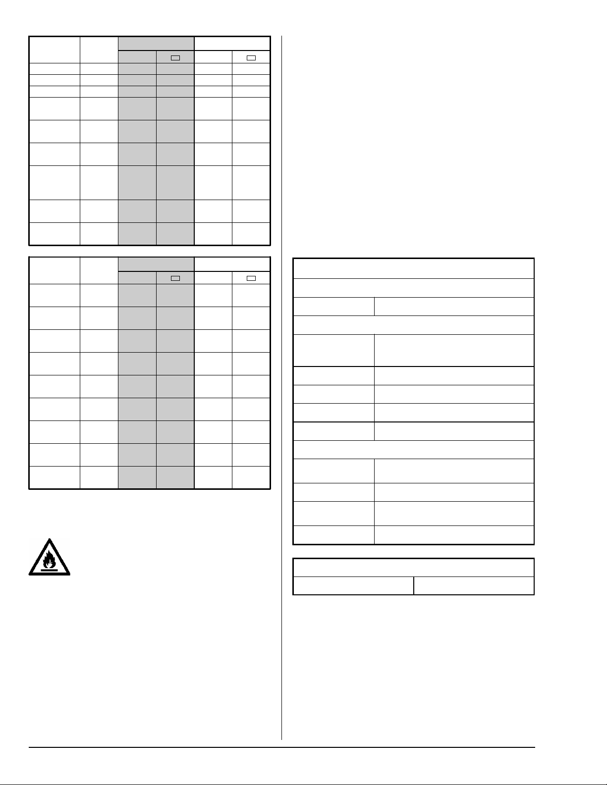
Gas Specifications
Gas Characteristics
Gas Type
(Category)
Gas
Symbol
H
MJ/m
To w ns Ga s
)
(I
1ab
Natural
/ I2E)
(I
2H
Natural
)
(I
2L
** Natural
)
(I
2E+
** Butane or
** Propane (I
Mix Butane &
Propane (I
3B/P
Propane
)
(I
3P
* Consult factory for elevations over 610m for correct burner injector size(s).
** Gas valve's internal regulator is disabled.
G110
G120
G20 37.78 17-25 9.0
G25 32.49 20-30 12.0
G20 37.78 20 –
G25 32.49 25 –
G30 125.81 28-30 –
)
3+
G31 95.65 37 –
G30 125.81 30/50 20.0
)
G31 95.65 37 25.0
15.87
17.77
Supply
s
Pressure
3
(mbar) mbar m3/H mm m3/H mm m3/H mm m3/H mm
6-15 3.5
Burner
Pressure
* ADG-25V * ADG-30V * ADG-50V * ADG-758V
2 Injectors 2 Injectors 3 Injectors 4 Injectors
Gas
Rate
Size
5.20 5.410 6.31 5.791 – –––
2.21 3.048 2.69 3.264 4.13 3.264 4.96 3.264
2.66 3.048 3.24 3.264 4.98 3.264 5.97 3.264
2.21
2.438
2.66 3.24 4.98 5.97
0.70
1.702
0.88 1.08 1.65 1.98
0.70 1.778 0.85 1.994 1.30 1.994 1.56 1.930
0.88 1.778 1.08 1.994 1.65 1.994 1.98 1.930
Injecto r
Gas
Rate
2.69
0.85
Inje cto r
Size
2.705
1.930
Gas
Rate
4.13
1.30
Injecto r
Size
2.794
1.930
Gas
Rate
4.96
1.56
Inje cto r
Size
2.705
1.854
AU and NZ Gas Specifications
Gas Characteristics
Supply
Gas Type
Pressure
kPa kPa m
NG 1.7 - 3.2 0.87
LPG 2.75 2.50 0.70 1.702 0.85 2.057 1.30 2.057 1.56 1.854
* Consult factory for elevations over 610m for correct burner injector size(s).
Burner
Pressure
Gas Type Conversion
This appliance must only operate with
the gas type indicated on the dryer's
rating plate. If the appliance is
converted for use with a gas type other than the one indicated,
a new rating plate must be obtained from the manufacturer.
Burner conversion must be performed by qualified personnel
in accordance with national and local safety regulations.
The required conversion kit will depend on the gas type and
the country the dryer is installed in.
Parts Required for Conversion:
1. Rating Plate (Data Badge)
2. Injector (refer to Gas Specification Chart)
* ADG-25V * ADG-30V * ADG-50V * ADG-758V
2 Injectors 2 Injectors 3 Injectors 4 Injectors
Gas
Rate
3
/H mm m3/H mm m3/H mm m3/H mm
Inje cto r
Size
Gas
Rate
Inje cto r
Size
Gas
Rate
Inje cto r
Size
Gas
Rate
2.21 3.048 2.69 3.454 4.13 3.454 4.96 3.264
3. Gas valve conversion kit:
Gas Valve Conversion Kit
Converting To Gas Valve Kit
I
/ I
2E+
3+
I
/ I
3B/P
3P
NG (AU / NZ)
I
/ I2H / I
ab
2E(LL)
/ I
2L
NG (AU / NZ)
* Disables gas valve's regulator. Adjust the gas supply pressure to the value
shown in the Gas Specification Chart.
* 140411
140413
140418
Inje cto r
Size
113686-1 www.adclaundry.com 11

Conversion Instructions
(Refer to figure)
1. Discontinue electrical power to the dryer.
2. Close shutoff valve in the dryer’s gas supply line.
3. Disconnect gas valve wiring (label wires first).
4. Disconnect the union (A) between the external shutoff and
the gas valve (B).
5. Remove screws (C) and remove the gas valve (B) with
manifold (D) assembly from the dryer.
6. Replace the main burner injector (E) with the correct injector
(see Gas Specification Chart).
7. Instructions on how to convert the gas valve is included
with the gas valve conversion kit (see chart).
8. Reverse step 4 to install the gas valve (B) with manifold
(D) assembly.
9. Open shutoff valve in the dryer’s gas supply line.
10. Test all connections for leaks.
11. Connect gas valve wires.
12. Continue electric power.
13. Provide proper gas pressure to the injector (see chart):
Gas supply pressure for categories I
regulated in the dryer's gas supply line.
All other gas categories require adjustment of the gas
valve's internal regulator; instructions below.
14. Replace the original rating plate with the rating plate.
and I3+ must be
2E+
Burner Pressure Measure and Adjust
(Refer to figure)
1. Discontinue electrical power to the dryer.
2. Turn the gas valve's switch (H) to "OFF" position.
3. Back out the miniature screw inside the outlet pressure
tap ("out P") (G).
4. Attach a manometer to pressure tap (G).
5. Turn the gas valve's switch (H) to the "ON" position.
6. Continue electrical power to the dryer.
7. Run a "heat" cycle and wait for burner ignition.
8. Gas manifold pressure can now be measured.
9. If the gas pressure does not need adjustment then
disconnect electric power and go to step 10, otherwise:
9.1. Disconnect electrical power to the dryer.
9.2. Regulator screw is under the regulator cap (F).
9.3. Remove the regulator cap (F) and turn the plastic
adjustment screw to alter the pressure (clockwise to
increase, or counterclockwise to decrease).
9.4. Continue electrical power to the dryer.
9.5. Run a "heat" cycle and wait for burner ignition.
9.6. Gas manifold pressure can now be measured.
9.7. If the manifold pressure needs further adjustment then
return to "Step 9.1."
9.8. Disconnect electrical power to the dryer.
9.9. Replace the regulator cap (F).
10. Turn the gas valve's switch (H) to "OFF" position.
11. Remove manometer and tighten pressure tap screw (G).
12. Turn the gas valve's switch (H) to "ON" position.
13. Continue electrical power to the dryer.
Steam Information ______________
Steam installation should be performed by
qualified personnel in accordance with national
and local safety regulations.
Care must be taken when leveling a steam dryer to promote
good steam coil drainage. Return lines should be level or
pitched down slightly for good drainage.
The steam supply to the coil must be from the top of a welldripped steam main. If the supply run-out to the dryer exceeds
6 meters then it should be dripped just before the control valve
with a proper trap and dirt pocket.
The normal pH level for copper-type steam coils must be
maintained between 8.5 and 9.5. For steel-type steam coils
the pH level must be between 9.5 to 10.5. These limits are
required to limit the acid attack of the steam coils.
Properly sized steam supply, and return, lines are required to
avoid poor performance.
Clean, dry steam must be provided to the dryer.
The steam supply connection into the main supply line must
be made with a minimum 25 cm riser. This will prevent any
condensate from draining towards the dryer.
The steam supply line to the dryer must include a 30 cm riser
along with a drip trap and check valve. This will prevent any
condensate from entering the steam coil.
Flexible hoses or couplings must be used. The dryer vibrates
slightly when operating which could cause steam connections
to crack if they are hard piped.
Horizontal sections of steam supply piping should be pitched
back towards the steam supply header (minimum slope of 1
cm for every meter) to allow any condensation to flow back
into the header. Install a bypass trap in any low point to eliminate
wet steam.
Failure to comply with the above requirements can result in
water hammer, premature component failure, and will void the
warranty.
12 American Dryer Corp. 113686-1

Steam Supply Requirements
Maximum Pressure 862 kPa
Minimum Pressure 689 kPa
Shutoff valves for each dryer should be installed in the supply
line, return line, and drip trap return line. This will allow the
dryer to be isolated from the steam supply if the dryer will be
serviced.
The supply and return lines should be insulated to save energy
and provide safety to maintenance personnel.
Pneumatic Steam Damper Arrangement
(Refer to figure)
A clean and dry compressed air supply (A) (5.5 bar ± 0.7 bar )
is required for dryers with a pneumatic piston (B) and damper
(C) arrangement.
The air connection is made to the steam damper solenoid valve
(D), which is located at the rear inner top area of the dryer just
in front of the rear electric service relay box (E).
Damper operation was calibrated prior to shipping. Airflow to
the piston (B) can be regulated by adjusting the flow control
valve (F). Turn the knob (G) clockwise to reduce airflow. Turn
the knob (G) counterclockwise to increase airflow.
1. Steam Coil
2. Vacuum Breaker
3. Solenoid Valve (for steam coil without damper)
4. Flexible Hose or Coupling
5. Riser
6. Strainer
7. Manual Shutoff Valve
113686-1 www.adclaundry.com 13
8. Drop
9. Dirt Leg
10. Drip Trap
11. Check Valve
12. Inverted Bucket Steam Trap
13. Return Main
14. Supply Main

Steam Damper System Operation
(Refer to the figure)
The steam damper arrangement allows the coil to be charged
continuously (eliminates repeated expansion and contraction).
During the heat cycle the damper (C) is in the open position.
Air (H) is heated as it passes through the hot coil (J) and into
the tumbler during the drying process.
During the cooldown cycle the damper (C) is in the closed
position. Air (H) will bypass the hot coil (J) and the cool air will
enter the tumbler during the cooldown phase.
Cooldown Cycle
Damper position
Heat Cycle
Damper position
Start-Up ___________________________________
Check:
• Gas dryers – All shutoff valves should be open.
• All back panels (guards) should be in position.
• Service doors should be securely closed.
• Lint door or drawer should be fully closed.
• The tumbler (drum) should rotate freely.
Tumbler Coating
The tumbler has a protective coating that should be wiped clean
with water and mild detergent solution (nonflammable).
Alternatively, tumble a load of old garments that are wetted
with water and mild detergent solution (nonflammable).
Preoperational Test
A performance check is needed after the dryer is fully installed
and before the dryer is ready for use.
Start the dryer (refer to the Operating Instructions below).
Gas heat – Check for flame ignition (may need more than one
attempt to purge air from the gas supply pipe).
Electric heat – Check the contactor(s) are cycling the electric
oven (heater) properly.
Steam heat – Check the damper (or steam solenoid valve, if
equipped) is functioning properly. Dampers should not bind or
slam during operation. If the damper motion is not smooth
and quiet then the flow control must be adjusted.
Water Information _______________
(If dryer is equipped with F.S.S.)
Water installation should be performed by qualified
personnel in accordance with national and local safety
regulations.
If the water system activates then you must have the dryer
inspected by a qualified agency. Do not operate the dryer.
Electric power to the dryer must be on at all times in order for
the fire suppression system (F.S.S.) to function.
The water connection is made into the rear of the dryer (refer
to the Technical Specifications page).
Use a new hose to connect to the water supply.
A flexible supply line, with coupling, must be used to avoid
damaging the water solenoid valve.
Water supply pipe size should be at least 1/2-inch (nominal)
(21.3 mm) and the supply pressure should be 275 ± 137 kPa.
Protect water lines from freezing if they will be exposed to
freezing-cold temperatures.
Safety Related Circuits
The dryer should stop when the main door is opened.
The dryer should stop when the lint door is opened.
If any failed test cannot be corrected, or if other concerns are
detected, contact your local service organization or dealer.
Ready for Use
If all tests are acceptable then the machine is ready for use.
Installer must instruct the end user on how to operate the dryer
before leaving.
Operating Instructions
Coin Models
The display will show “Ready, Insert
the dryer is ready for use.
Insert the required coin(s). The display will show “Select
Temperature” when the “amount-to-start” has been satisfied.
Select the desired cycle by pressing “HI,” “MED,” or “LO.”
The dryer will start and display the cycle and remaining time.
Press “
Non-Coin Models
The display will show “Ready” when the dryer is ready for use.
Press the letter on the keypad to select the desired cycle.
The dryer will start and display the cycle and remaining time.
Press “
Press the “
resume the current cycle, or select a different cycle to restart.
” to pause the dryer. Select desired cycle to restart.
” to stop the dryer.
” key again to clear the dry cycle, press “ ” to
amount
to Start” when
14 American Dryer Corp. 113686-1

Routine Maintenance _____________________
A schedule should be established for the periodic inspection,
cleaning, and lint removal. The frequency of cleaning can best
be determined from experience at each location. Ideal drying
performance depends on sufficient airflow. Lint accumulation
can restrict airflow and is also a fire hazard.
Avoid using harsh chemicals when cleaning the dryer.
Suggested Cleaning Schedule
(Based on approximately 6-8 hours of daily operation)
To avoid electric shock and contacting
moving parts, discontinue electrical
supply any time a panel (without an
interlock switch) or guard is removed.
Every Three or Four Loads
Clean the lint screen – located behind the lint door (lower front
panel). The 50V and 758V have a lint drawer that slides out for
cleaning. Replace the lint screen if it is torn or damaged.
Weekly
Clean lint accumulation from the lint chamber, thermostat and
operating temperature sensor (located just below the drum).
Steam dryers: carefully clean steam coil fins (which are easily
damaged). We suggest using a vacuum cleaner with brush
attachment. Straighten bent fins with a fin comb.
Data Label Information ___________________
When contacting ADC, certain information is required to ensure
proper service/parts information from ADC. This information is
on the data label affixed to the right side panel area at the rear
of the dryer. When contacting ADC, please have the model
number and serial number available.
1. MODEL – Dryer model number.
2. SERIAL NUMBER – Unique identification number.
3. GAS TYPE – Gas type the dryer is constructed for.
4. HEAT INPUT – Rate of combustion
5. ORIFICE SIZE – Injector opening (in mm).
6. ELECTRIC SERVICE – Electric supply type.
7. GAS PRESSURE – Supply and regulated pressure.
CE Rating Plate
90 Days
Clean any lint accumulation in and around the dryer.
Particular attention must be given to the removal of lint from
the burner area - located behind the upper front panel (control
door) and the area near the drive and fan motors.
Caution: Avoid touching the igniter and flame-sensor probes.
6 Months
Remove lint accumulation in the fresh-air intake openings and
in the exhaust ductwork.
Remove lint that may interfere with any back-draft damper.
Check all back-draft dampers for proper operation.
Service / Parts Information ______________
Service must be performed by a qualified technician. If service
is required, contact the reseller who sold you the equipment. If
the reseller cannot be reached then contact our Service
Department for a reseller in your area.
Replacement parts can be obtained from your reseller or the
ADC factory. When ordering replacement parts from the factory,
you can FAX your order to ADC at +1 (508) 678-9447 or
telephone our Parts Department at +1 (508) 678-9000. Please
be prepared to provide the dryer model number, serial number,
description of the part, and the part number (if known).
This dryer is equipped with a manually resettable high-limit
thermostat in the lint compartment area.
The wiring diagram for the dryer is located behind the control
panel.
AGA Rating Plate
113686-1 www.adclaundry.com 15

Warranty Information _____________________
For any warranty-related issues, please contact our Warranty
Department at +1 (508) 678-9000.
If you need a copy of the warranty covering your dryer please
contact the reseller who sold you the equipment. If the reseller
cannot be contacted then call our Warranty Department.
Before calling, please have the dryer model and serial number
(from rating plate) and the installation date of the dryer.
The rating plate can be found behind the control panel on some
dryers and inside the back guard on other dryers.
All warranty claims or inquiries should be addressed to our
Warranty Parts Department. To expedite warranty claim, please
follow these procedures:
Do not ship any part to us without proper authorization (Return
Material Authorization or R.M.A.) from the factory. An R.M.A. is
only valid for 30 days.
Ship the failed component, a copy of the R.M.A., and any other
supporting documentation.
Label or tag each part with the model and serial number (from
the rating plate) of the dryer it was removed from. Warranty
tags (Part No. 450064) are available (no charge) from ADC.
Describe the nature of the failure (be specific).
Provide the date that the dryer was installed.
Provide the date when the component failed.
Specify if the part is being returned for a credit, replacement,
or refund. If a part is marked for a credit or a refund, please
provide the invoice number of the replacement part purchase.
You must clearly note your company’s complete name and
address on the outside of the package.
All returns should be shipped to the factory with adequate
insurance and “proof-of-delivery” from the shipping company.
No replacements, credits, or refunds will be issued for
components damaged during transit. All returns must be
properly packaged to prevent such damage, and any claims
are the responsibility of the shipper.
Shipping charges are your responsibility. Any C.O.D. or “Collect”
shipments will be refused.
You will be notified if your warranty claim cannot be processed
due to insufficient or missing information. We must receive this
information within 30 days otherwise the claim will be rejected
and the part will be discarded.
For your convenience, log the following information:
This product embodies advanced concepts in engineering,
design, and safety. If this product is properly maintained, it will
provide many years of safe, efficient, and trouble-free operation.
We have tried to make this manual as complete as possible
and hope that you will find it useful. The manufacturer reserves
the right to make changes from time to time and without notice
or obligation. The illustrations included in this manual may not
depict your particular dryer exactly.
NOTES ______________________________________________________
_____________________________________________________________
_____________________________________________________________
_____________________________________________________________
_____________________________________________________________
_____________________________________________________________
_____________________________________________________________
_____________________________________________________________
_____________________________________________________________
_____________________________________________________________
_____________________________________________________________
_____________________________________________________________
Date of Purchase: ________________________________
Model Number: __________________________________
Reseller's Name: _________________________________
Serial Number: ___________________________________
_______________________________________________
_______________________________________________
ADC Part No. 113686 1 - 12/18/15
_____________________________________________________________
_____________________________________________________________
_____________________________________________________________
 Loading...