

Page 1

AD-170
Par ts Manual
Phase 5
For Models Mfd. prior to October 7, 1994
American Dryer Corporation
88 Currant Road
Fall River, MA 02720-4781
Telephone: (508) 678-9000 / Fax: (508) 678-9447
E-mail: techsupport@amdry.com
www.amdry.com
ADC Part No. 450126 -8
Page 2

Retain This Manual In A Safe Place For Future Reference
American Dryer Corporation products embody advanced concepts in engineering, design, and safety . If this product
is properly maintained, it will provide many years of safe, efficient, and trouble free operation.
ONLY qualified technicians should service this equipment.
OBSERVE ALL SAFETY PRECAUTIONS displayed on the equipment or specified in the inst allation manual included
with the dryer.
The following “FOR YOUR SAFETY” caution must be posted near the dryer in a prominent location.
FOR YOUR SAFETY
Do not store or use gasoline or
other flammable vapors and
liquids in the vicinity of this or
any other appliance.
We have tried to make this manual as complete as possible and hope you will find it useful. ADC reserves the right
to make changes from time to time, without notice or obligation, in prices, specifications, colors, and material, and
to change or discontinue models.
Ne pas entreposer ni utiliser d’essence
ni d’autres vapeurs ou liquides
inflammables à proximité de cet appareil
ou de tout autre appareil.
POUR VOTRE SÉCURITÉ
Important
For your convenience, log the following information:
DATE OF PURCHASE ___________________________________________________ MODEL NO. ______________
RESELLER’S NAME _________________________________________________________________________________
Serial Number(s) ____________________________________________________________________________________
AD-170
____________________________________________________________________________________________________
____________________________________________________________________________________________________
Replacement parts can be obtained from your reseller or the ADC factory. When ordering replacement parts from
the factory, you can FAX your order to ADC at (508) 678-9447 or telephone your order directly to the ADC Parts
Department at (508) 678-9000. Please specify the dryer model number and serial number in addition to the description
and part number, so that your order is processed accurately and promptly.
The illustrations on the following pages may not depict your particular dryer exactly . The illustrations are a composite
of the various dryer models. Be sure to check the descriptions of the parts thoroughly before ordering.
“IMPORTANT NOTE TO PURCHASER”
Information must be obtained from your local gas supplier on the
instructions to be followed if the user smells gas. These
instructions must be posted in a prominent location near the dryer.
Page 3

Table of Contents
Control Door Assembly...............................................................................................................................................4
Microprocessor Control Panel Assembly....................................................................................................................5
Single Timer Control Panel Assembly ........................................................................................................................6
Control Box Assembly ................................................................................................................................................7
Front Panel / Main Door Assemblies..........................................................................................................................8
Main Door Switch Assembly.....................................................................................................................................10
Drop Lint Door Assembly.......................................................................................................................................... 11
Lint Drawer / Lint Drawer Switch Box Assemblies....................................................................................................12
Tumbler / Support Assemblies .................................................................................................................................13
Tumbler Bearing Mount Assembly ...........................................................................................................................14
Idler Bearing Mount Assembly................................................................................................... ...............................15
Totally Enclosed, Fan-Cooled Tumbler Motor Mount Assembly ...............................................................................16
Blower Motor Mount Assembly for 60 Hz Gas Models ONLY...................................................................................17
Blower Motor, Fan, and Shaf t Assembly for 60 Hz Steam Models and 50 Hz Gas Models ONL Y ...........................18
Blower Motor, Fan, and Shaf t Assembly for 50 Hz Steam Models ONL Y.................................................................20
Direct Spark Ignition Burner Assembly for Gas Models ONLY .................................................................................22
Steam Damper Assembly .........................................................................................................................................24
Microprocessor Temperature Sensor Bracket Assembly .........................................................................................25
Timer Temperature Sensor Bracket Assembly.........................................................................................................26
Direct Spark Ignition Module Mount Assembly for Gas Models ONLY .....................................................................27
Sail Switch Assembly ...............................................................................................................................................28
Microprocessor Reversing Control Box Assembly ................................................................................................... 29
Timer Reversing Control Box Assembly...................................................................................................................30
Back Guard Assembly..............................................................................................................................................31
Additional Parts Available .........................................................................................................................................32
Page 4
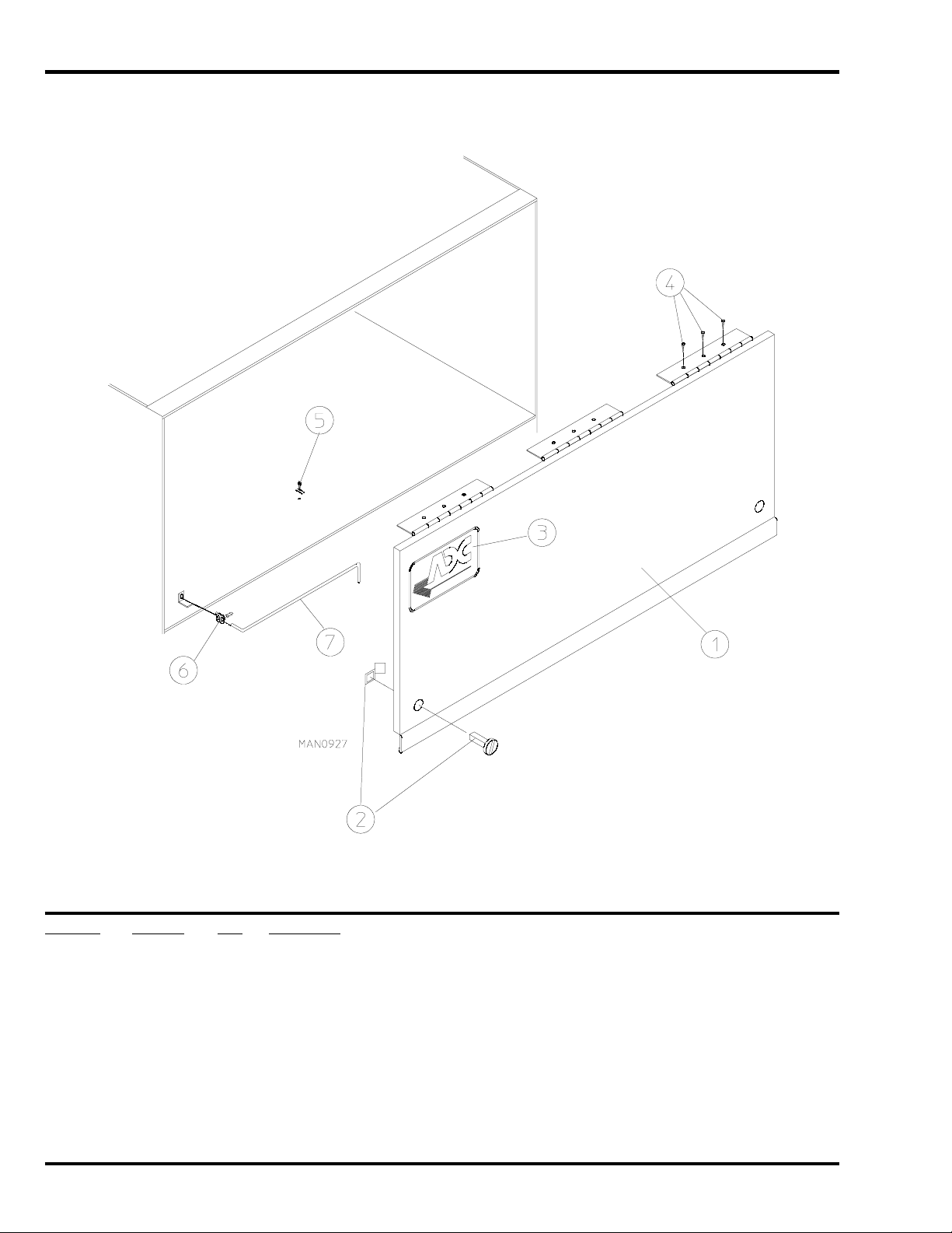
Control Door Assembly
Illus. No. Part No. Qty. Description
1* 820944 1 Control Door Assembly ONLY (for Gas Models Only)
820963 1 Short Control Door ONLY (for Steam Models Only)
2 160005 2 Spring Turn Latch (2-piece)
3 112360** 1 ADC Logo ONLY
870011 1 Logo Double Tape Kit
4 150415 9 #10-16 x 1/2” Phillips Round Head Crimptite Screw
5 102600 1 Control Door Support Rod Catch
6 102601 1 Control Door Rod Retainer Clip
7 102505 1 Control Door Support Rod
* Specify color when ordering.
** Logo tape kit not included and must be ordered separately.
4 American Dryer Corporation 450126- 8
Page 5
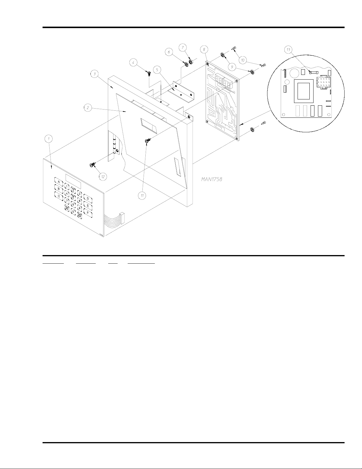
Microprocessor Control Panel Assembly
Illus. No. Part No. Qty. Description
1 112535 1 Non-Coin English Keypad Label Assembly
112276 1 Non-Coin Stick-On Labels
(English Only) … Not Illustrated
112275 1 Non-Coin Stick-On Labels
(Spanish, Italian, and Hebrew) … Not Illustrated
112277 1 3-Language Non-Coin Stick-On Labels
(English, Spanish, and Hebrew) … Not Illustrated
112278 1 5-Language Non-Coin Stick-On Labels
(Italian, Dutch, French, German, and Chinese) … Not Illustrated
2 820935 1 Swing Out Computer Drawer Complete
(includes illus. nos. 1 through 10 and 13)
3 820912 1 Control Box Door
4 150000 1 #6-32 x 1/4” Slotted Round Head Screw
5 332200 1 Computer Drawer Angle
6 153010 2 #6 Star Washer
7 152010 2 #6-32 Hex Nut
8 137231 1 Phase 5 Non-Coin Reversing Microprocessor Controller ONLY
9 153010 4 #6 Star Washer
10 150005 4 #6-32 x 1/4” Phillips Round Head Machine Screw
11 150000 1 #6-32 x 1/4” Slotted Round Head Machine Screw
12 150000 3 #6-32 x 1/4” Slotted Round Head Machine Screw
13 136048 1 1/8-Amp (Slo-Blo) Fuse
IMPORTANT: Check label on computer chip to verify correct part number.
450126-8 www.amdry.com 5
Page 6
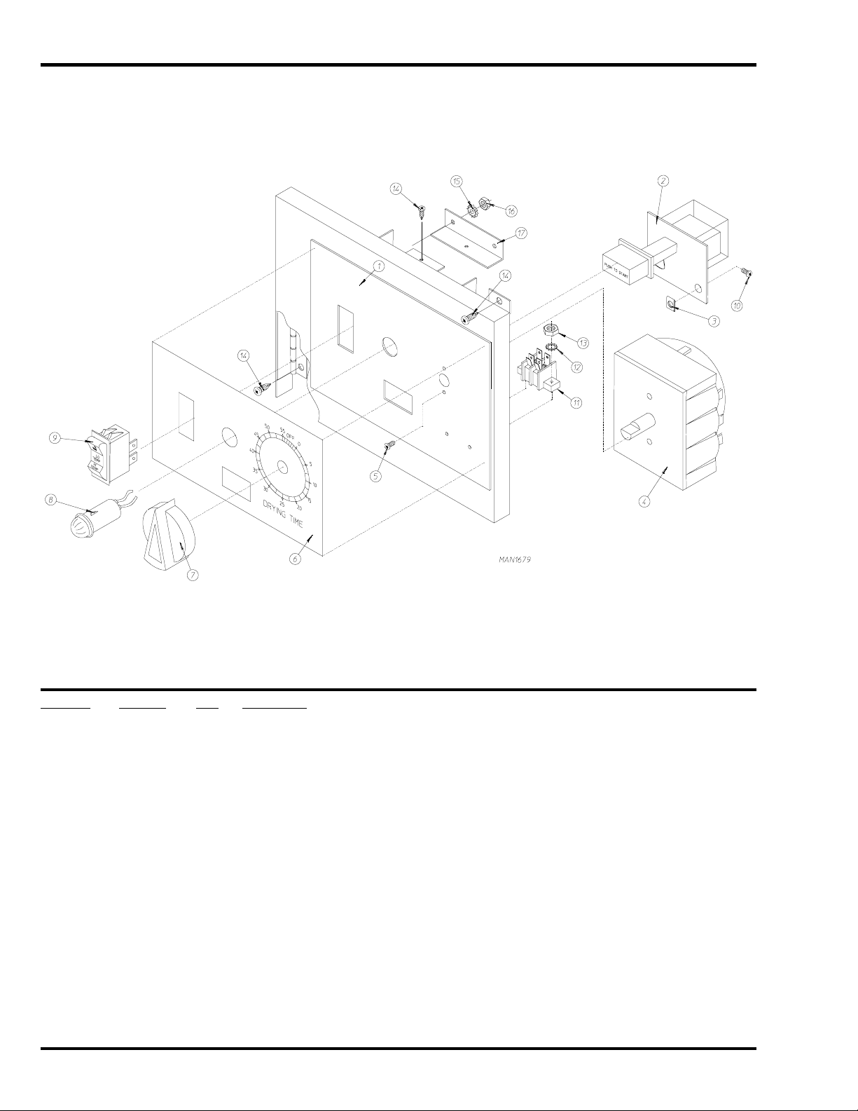
Single Timer Control Panel Assembly
Illus. No. Part No. Qty. Description
1 880940 1 Single Timer Control Panel Assembly Complete
(includes illus. nos. 1 through 17)
821015 1 Single Timer Control Panel ONLY
2 131917 1 Push-to-Start Relay – 24 VAC
3 154001 2 #10-24 Speed Nut
4 124025 1 60 Minute Timer – 24 VAC
5 150110 2 #8-32 x 1/4” Phillips Round Head Screw
6 112048 1 Single Timer Label
7 124103 1 Arrow Timer Knob
8 123005 1 Red Light Indicator – 24 VAC
9 122400 1 Rocker Heat Selector Switch
10 150207 2 #10-24 x 1/2” Round Head Machine Screw
11 120707 1 Terminal Strip
12 153010 2 #6 Star Washer
13 152000 2 #6-32 Hex Nut
14 150301 5 #8-18 x 7/16” Phillips Pan Head TEK Screw
15 153012 2 #8 Star Washer
16 152001 2 #8-32 Hex Nut
17 332257 1 Single Timer Drawer Stop
6 American Dryer Corporation 450126- 8
Page 7
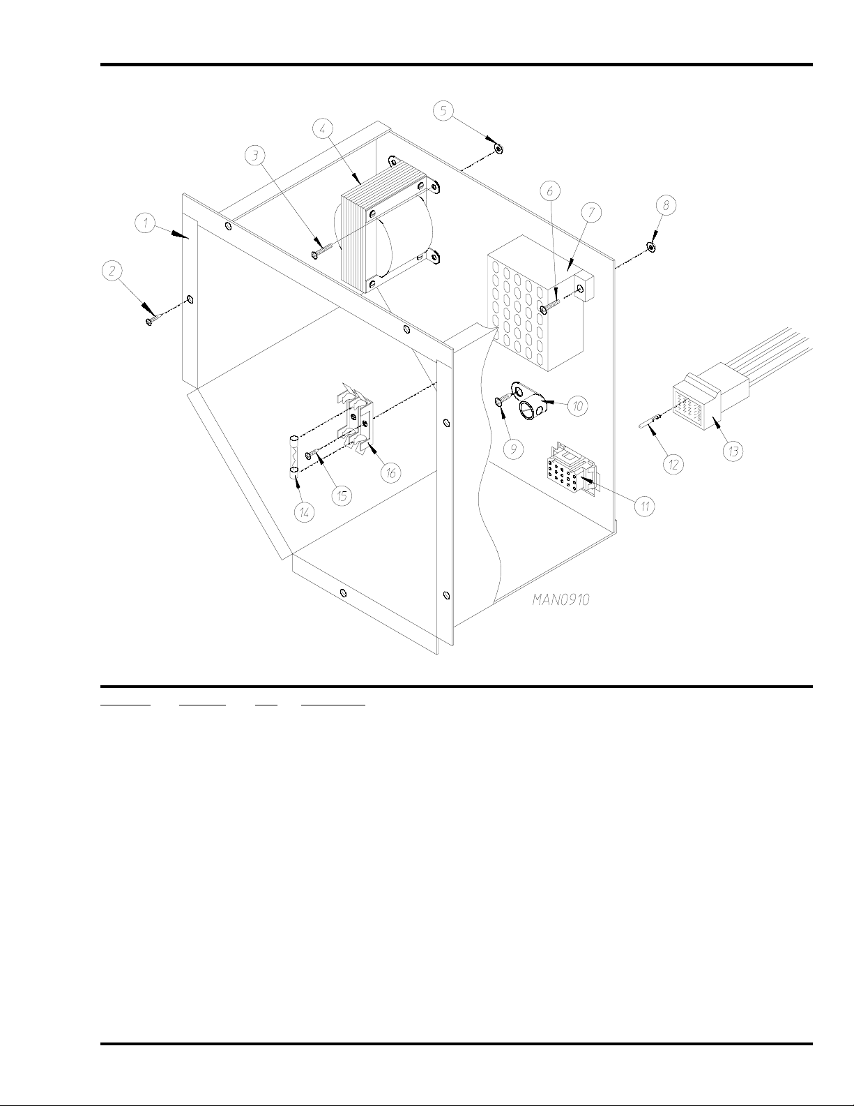
Control Box Assembly
Illus. No. Part No. Qty. Description
1 820940 1 Control Box Assembly Complete
(includes illus. nos. 1, 2, 6 through 10, 14, 15, and 16)
2 150301 6 #8-32 x 7/16” Phillips Round Head TEK Screw
3 150100 2 #8-32 x 1/2” Round Head Machine Screw
4 141403 1 24 VAC Transformer
5 151001 2 #8-32 Pal Nut
6 150002 2 #6-32 x 1” Round Head Machine Screw
7 120715 1 30-Position Terminal Block
8 151000 2 #6-32 Pal Nut
9 150415 1 #10-16 x 1/2” Phillips Round Head Crimptite Screw
10 121010 1 L-70 Ground Lug
11 122626 1 15-Pin Socket Connector
12 122704 14 Pin Terminal
13 122625 1 15-Pin Connector
14 136057 2 1/2-Amp (Slo-Blo) Fuse
15 150301 1 #8-32 x 7/16” Phillips Round Head TEK Screw
16 136008 2 Fuse Block / Strip
— 122800 1 Microprocessor (female) Pin Extraction Tool
— 122801 1 Pin / Socket Extraction Tool
450126-8 www.amdry.com 7
Page 8
Front Panel / Main Door Assemblies
8 American Dryer Corporation 450126- 8
Page 9

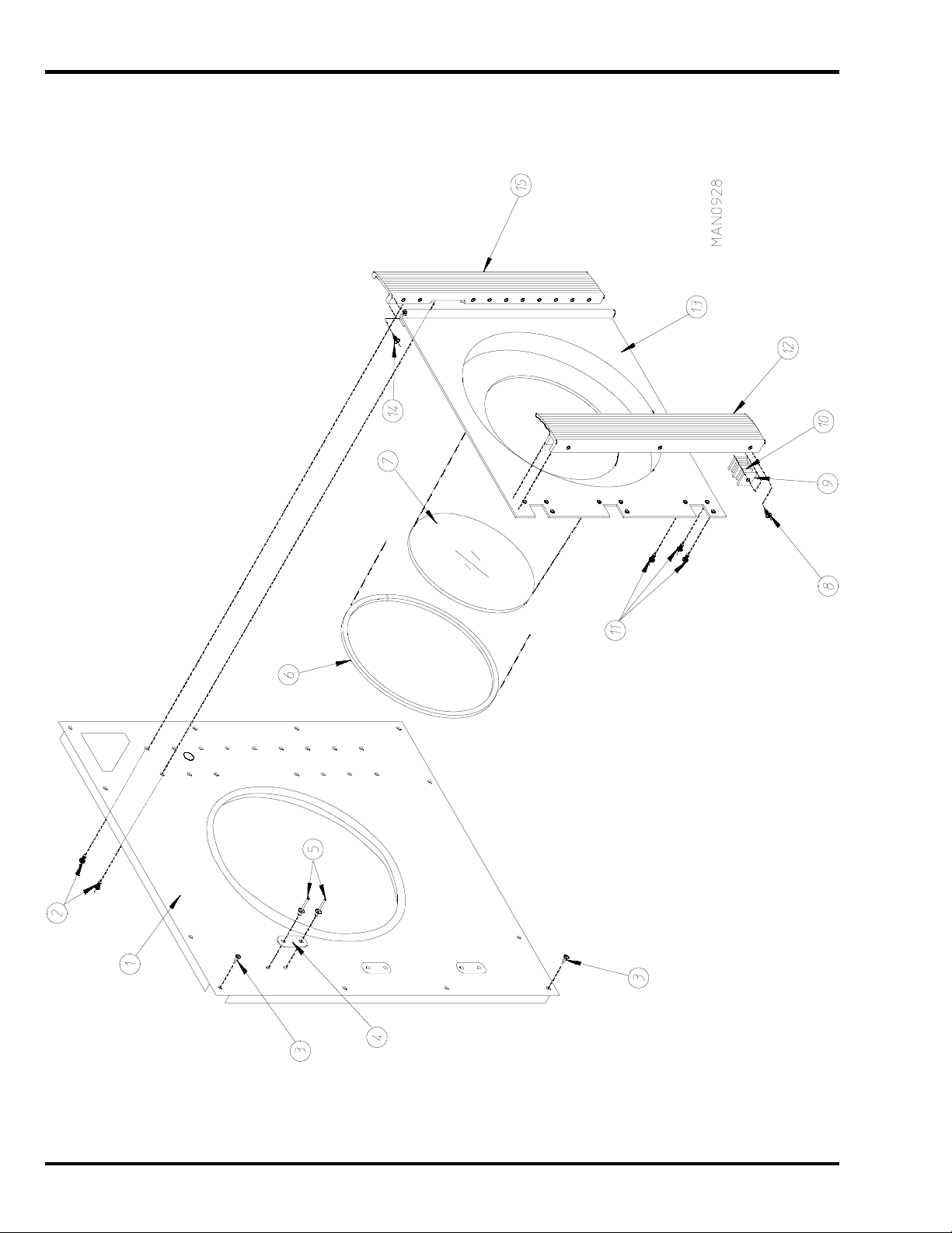
Front Panel / Main Door Assemblies
Illus. No. Part No. Qty. Description
1* 820929 1 Right-Hand Front Panel Assembly
(includes illus. nos. 1, 4, and 5)
2 150415 15 #10-16 x 1/2” Phillips Round Head Crimptite Screw
3 150412 12 #10-16 x 3/4” Phillips Round Head Crimptite Screw
4 170340 3 3-1/2” Stainless Steel Striker Pad
5 154200 6 5/32” Pop Rivet
6 102308 1 Door Gasket ONLY (94” length)
7 102210 1 20-7/16” Door Glass ONLY
170730 1 Door Glass Adhesive (10.3 oz. cartridge)
8 150401 3 #10-24 x 1-1/4” Phillips Taptite Screw
9 306801 6 Magnet Keeper ONLY
10 102100 6 1” x 1” x 1/4” Main Door Magnet ONLY
11 150415 9 #10-16 x 1/2” Phillips Round Head Crimptite Screw
12 180151 1 35” Granite Main Door Handle ONLY
(for models mfd. as of March 8, 1993)
180150 1 35” Gray Main Door Handle ONLY
(for models mfd. prior to March 8, 1993)
13 800265* 1 Main Door Assembly Complete with Granite Handle
(for models mfd. as of March 8, 1993)
(includes illus. nos. 6 through 13)
800127* 1 Main Door Assembly Complete with Gray Handle
(for models mfd. prior to March 8, 1993)
(includes illus. nos. 6 through 13)
800266 1 Stainless Steel Main Door Assembly Complete with Granite Handle
(for models mfd. as of March 8, 1993)
(includes illus. nos. 6 through 13)
800128 1 Stainless Steel Main Door Assembly Complete with Gray Handle
(for models mfd. prior to March 8, 1993)
(includes illus. nos. 6 through 13)
800122* 1 Main Door Assembly with Glass and Gasket ONLY
(includes illus. nos. 6, 7, and 13)
800125 1 Stainless Steel Main Door Assembly with Glass and Gasket ONLY
(includes illus. nos. 6, 7, and 13)
14 150430 11 #10 x 1/2” Phillips Self-Drilling Screw
15 180156 1 35” Granite Main Door Hinge Block ONLY
(for models mfd. as of March 8, 1993)
180155 1 35” Gray Main Door Hinge Block ONLY
(for models mfd. prior to March 8, 1993)
* S pecify color when ordering.
450126-8 www.amdry.com 9
Page 10
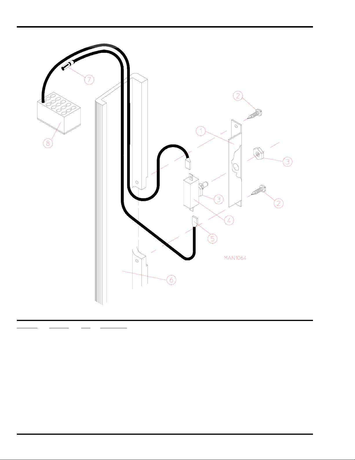
Main Door Switch Assembly
Illus. No. Part No. Qty. Description
1 313208 1 Door Switch Bracket
2 150415 2 #10-16 x 1/2” Phillips Round Head Crimptite Screw
3 152003 2 3/8-32 x 1/2” x 1/16” Door Switch Nut
4 136995 1 Door Switch
(for models mfd. as of June 26, 1992)
137006 1 Door Switch
(for models mfd. prior to June 26, 1992)
5 121028 2 1/4” x .032 Insulated Terminal
6 180156 1 35” Granite Main Door Hinge Block
(for models mfd. as of March 8, 1993)
180155 1 35” Gray Main Door Hinge Block
(for models mfd. prior to March 8, 1993)
7 122705 2 Socket Mate to Split Pin
8 122626 1 15-Pin Cap Housing ONLY (M / L)
10 American Dryer Corporation 450126- 8
Page 11
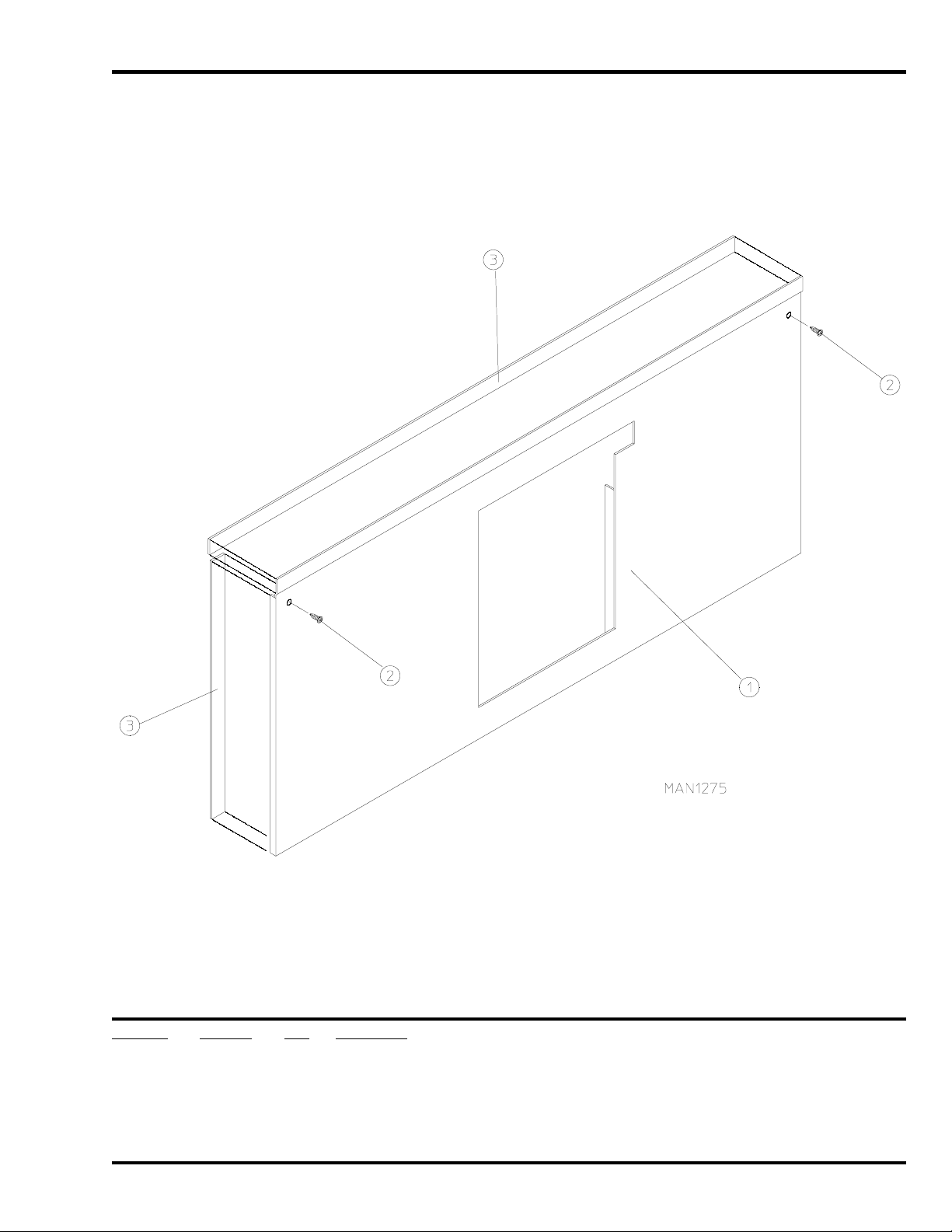
Drop Lint Door Assembly
Illus. No. Part No. Qty. Description
1* 820945 1 Drop Lint Door Assembly
(includes illus. nos. 1 and 3)
2 150415 5 #10-16 x 1/2” Phillips Round Head Crimptite Screw
3 117600 9 Noise Suppressor Tape (sold by the foot)
* Specify color when ordering.
450126-8 www.amdry.com 11
Page 12
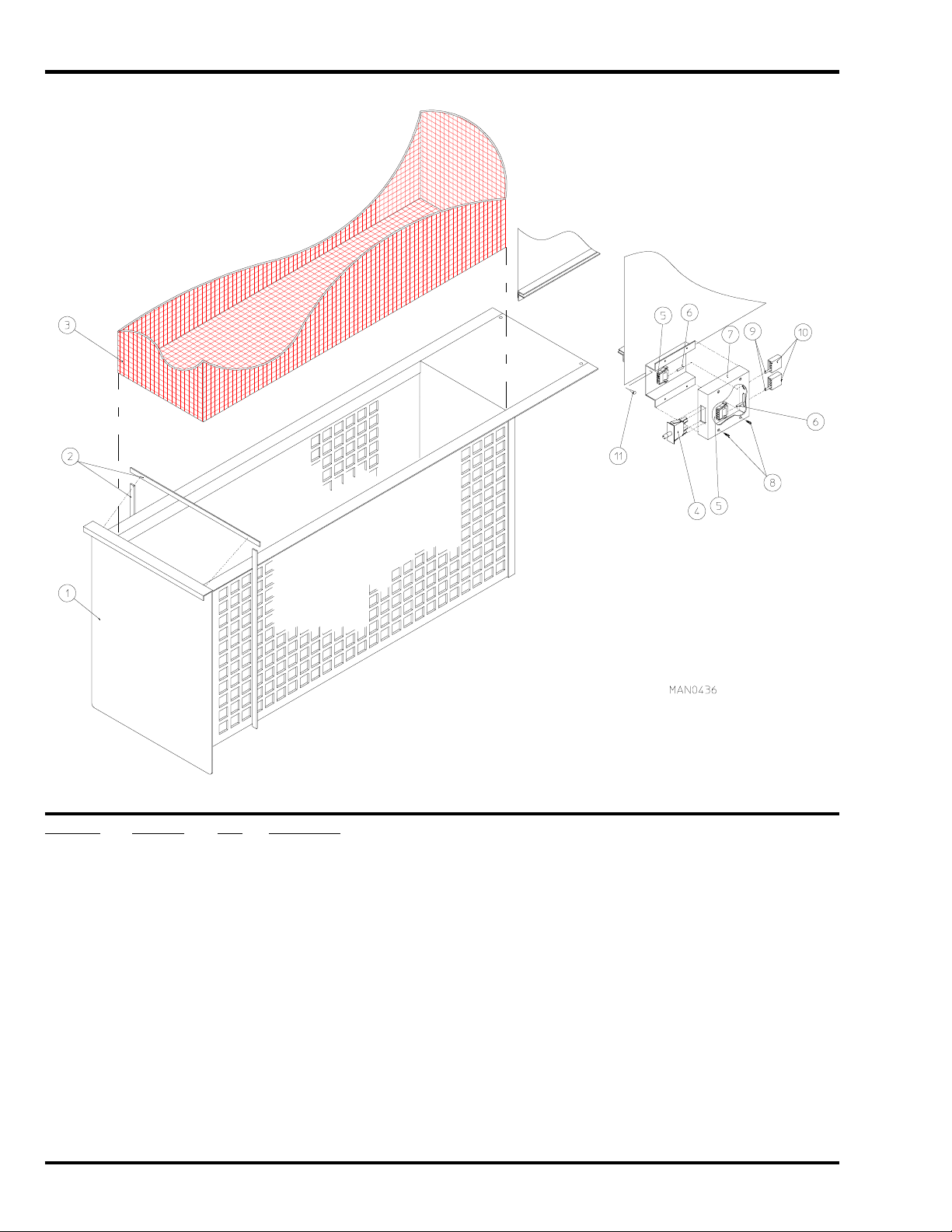
Lint Drawer / Lint Drawer Switch Box Assemblies
Illus. No. Part No. Qty. Description
1* 820955 1 Lint Drawer Assembly Complete
(includes illus. nos. 1 and 2)
2 117602 7 Noise Suppressor Tape (sold by the foot)
3 820925 1 Lint Screen Assembly
4 122116 1 Lint Drawer Switch
5 122605 2 4-Pin Socket Connector
6 122701 8 Socket Terminal
122801 1 Pin / Socket Extraction Tool
7 800264 1 Lint Drawer Switch Box Assembly Complete
(includes illus. nos. 4 through 7)
304034 1 Lint Drawer Switch Box ONLY
8 150301 4 #8-18 x 7/16” Phillips Pan Head TEK Screw
9 122700 8 Pin Terminal
10 122604 2 4-Pin Connector
11 150301 2 #8-18 x 7/16” Phillips Pan Head TEK Screw
* Specify color when ordering.
12 American Dryer Corporation 450126- 8
Page 13
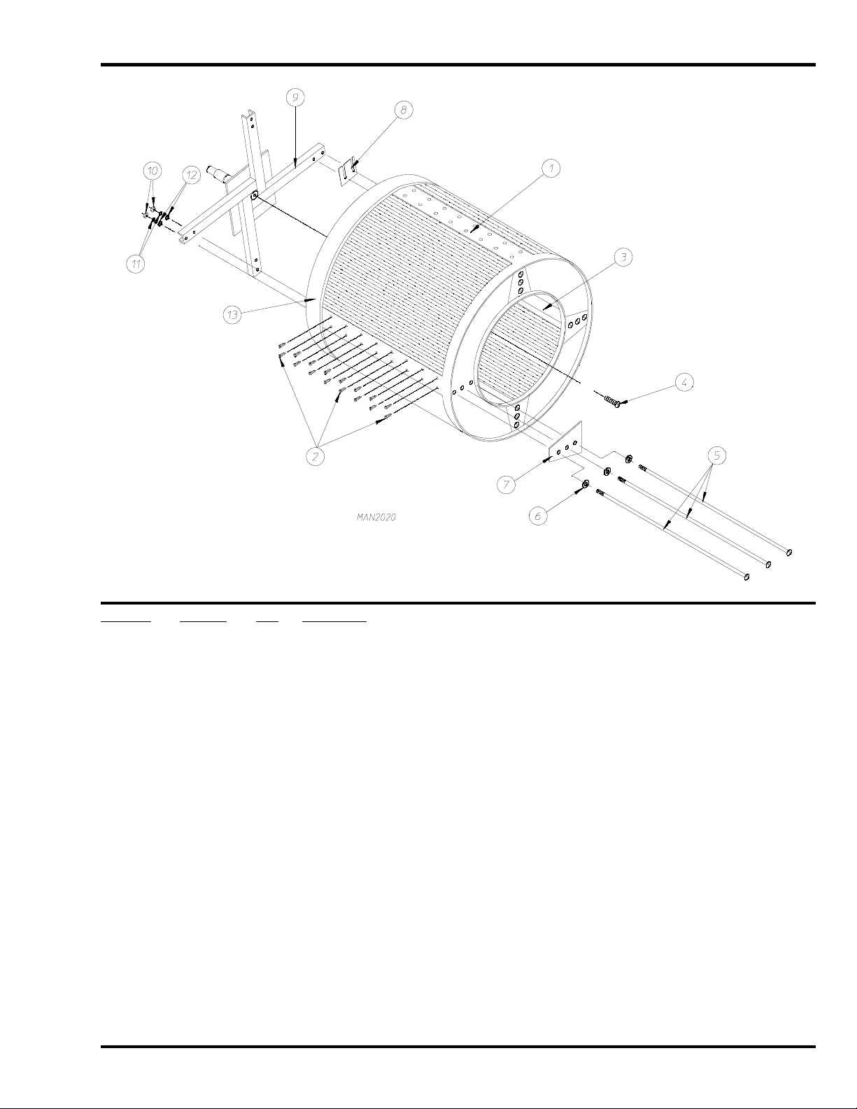
Tumbler / Support Assemblies
Illus. No. Part No. Qty. Description
1 820979* 1 Tumbler ONLY without Felt Collar
821001 1 Tumbler and Support Assembly Complete with Rotational Sensor Option
(for models mfd. as of March 1, 1993)
(includes illus. nos. 1 through 13)
820927 1 Tumbler and Support Assembly Complete without Rotational Sensor Option
(includes illus. nos. 1 through 13)
2 150415 64 #10-16 x 1/2” Phillips Round Head Crimptite Screw
3 332140 4 Tumbler Rib
4 150500 1 5/16-18 x 3/4” Socket Button Head Screw
5 880967 12 1/2-13 x 44” Tie Rod Kit with Hardware
(includes 1 each ONLY of illus. nos. 5, 6, 10, and 11)
6 153011 12 9/16” Flat Washer
7 332139 4 Basket Reinforcing Plate
8 332177 ** Tumbler Shim
9 821000 1 Tumbler Support with Rotational Sensor Option
(for models mfd. as of March 1, 1993)
820909 1 Tumbler Support without Rotational Sensor Option
10 152011 12 1/2-13 Hex Nut
11 153026 12 1/2” Lock Washer
12 153014 12 7/16” Flat Washer
13 116007 1 Felt Collar
— 401010 1 #847 Adhesive for Felt Collar
* Felt collar not included and must be ordered separately.
** As required.
450126-8 www.amdry.com 13
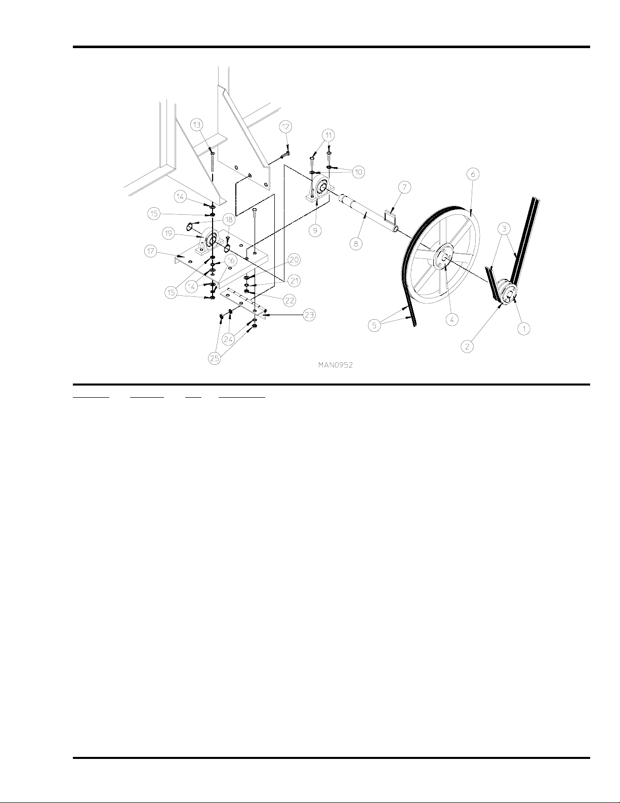
Page 14

Tumbler Bearing Mount Assembly
Illus. No. Part No. Qty. Description
1 101137 1 2-1/4” SFX Bushing
2* 100137 2 AB91 V-Belt
3 101182 1 25” Tumbler Pulley
4 150602 4 5/8-11 x 3” Hex Head Machine Bolt
5 153016 4 5/8” Flat Washer
6 100223 1 3-1/8” Pillow Block Bearing ONLY
7 153016 4 5/8” Flat Washer
8 153015 4 5/8” Lock Washer
9 152010 4 5/8-11 Hex Nut
10 150600 2 3/8-16 x 1-1/2” Hex Head Machine Bolt
11 152005 2 3/8-16 Hex Nut
12 820910 1 Tumbler Bearing Mount
13 100223 1 3-1/8” Pillow Block Bearing
14 150604 2 1/2-20 x 3” Square Head Machine Bolt
15 152012 2 1/2-20 Hex Nut
16 152005 2 3/8-16 Hex Nut
17 153005 2 3/8” Lock Washer
18 153004 4 3/8” Flat Washer
19 150600 2 3/8-16 x 1-1/2” Hex Head Machine Bolt
20 153004 2 3/8” Flat Washer
21 100801 2 5/8” Retaining Ring
22 332153 1 5/8” Hinge Pin
23 100810 2 3-1/8” Retaining Ring
24 153018 2 1/4” Flat Washer
25 153007 2 1/4” Lock Washer
26 150512 2 1/4-20 x 1/2” Hex Head Machine Bolt
27 824807 1 Rotational Sensor Assembly
28 880841 1 Rotational Sensor Mounting Bracket
* Replace in matched sets (both belt s).
14 American Dryer Corporation 450126- 8
Page 15
Idler Bearing Mount Assembly
Illus. No. Part No. Qty. Description
1 101152 1 SH x 1-3/8” Bushing
2 101143 1 2B 3.8 SH Pulley
3* 100137 2 AB91 V-Belt
4 101184 1 SK x 1-3/8” Bore Bushing
5* 100102 2 3V740 V-Belt
6 101112 1 19” Idler Pulley
7 100730 1 1/4” x 1/4” x 4-5/8” Key
8 332152 1 Idler Shaft
9 880879 1 1-3/8” Pillow Block Bearing with Setscrews and Grease Fitting
10 153004 4 3/8” Flat Washer
11 150600 4 3/8-16 x 1-1/2” Hex Head Machine Bolt
12 150504 6 1/4-20 x 1/2” Hex Head Machine Bolt
13 150509 2 5/16-18 x 3” Hex Head Machine Bolt
14 153001 6 5/16” Flat Washer
15 152004 6 5/16-18 Hex Nut
16 153002 8 5/16” Lock Washer
17 820932 1 Idler Bearing Mount Assembly Complete
(includes illus. nos. 8 through 11 and 17 through 25)
332151 1 Idler Bearing Mount ONLY
18 100802 2 1-3/8” Retaining Ring
19 880879 1 1-3/8” Pillow Block Bearing with Setscrews and Grease Fitting
20 153004 4 3/8” Flat Washer
21 153005 4 3/8” Lock Washer
22 152005 4 3/8-16 Hex Nut
23 103005 1 Idler Adjustment Hinge
24 153002 6 1/4” Lock Washer
25 152004 6 1/4-20 Hex Nut
* Replace in matched set s (both belts).
450126-8 www.amdry.com 15
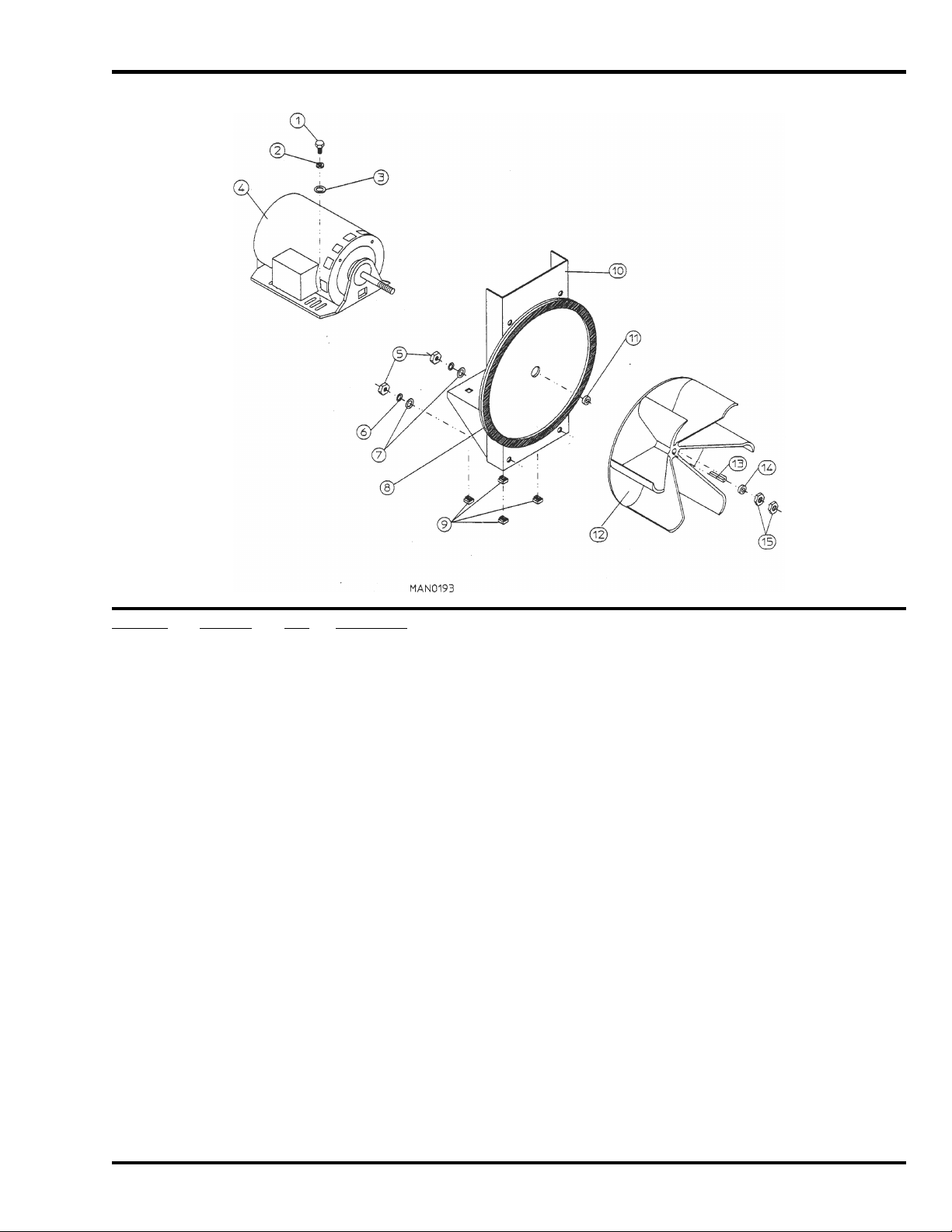
Page 16

Totally Enclosed, Fan-Cooled Tumbler Motor Mount Assembly
Illus. No. Part No. Qty. Description
1 101121 1 5/8” SK Bushing
2 101114 1 2.65” Pulley (for 60 Hz Models Only)
101120 1 3.15” Pulley (for 50 Hz Models Only)
3* 100102 2 3V740 V-Belt
4 120200 1 3/8” x 90° Connector
5 150501 4 5/16-18 x 3/4” Hex Head Machine Bolt
6 153001 4 5/16” Flat Washer
7 100050 1 1 hp 208 / 230 / 380 / 460v 50 / 60 Hz 3ø Totally Enclosed, Fan-Cooled Motor (56Z frame)
8 800952 1 Tumbler Motor Mount ONLY (56Z frame)
820941** 1 50 / 60 Hz Totally Enclosed, Fan-Cooled Tumbler Motor Mount Assembly Complete
(includes illus. nos. 1 and 4 through 11)
NOTE: Motor Pulley Must Be Ordered Separately
9 152004 4 5/16-18 Hex Nut
10 153002 4 5/16” Lock Washer
11 153001 4 5/16” Flat Washer
12 152004 4 5/16-18 Hex Nut
13 153002 4 5/16” Lock Washer
14 153001 4 5/16” Flat Washer
15 150619 1 3/8-16 x 3” Hex Head Machine Bolt
16 152005 2 3/8-16 Hex Nut
* Replace in matched sets (both belt s).
** Specify voltage when ordering.
IMPORTANT: For voltages higher than 460v / contact the factory for correct part number of motor or motor mount assembly.
16 American Dryer Corporation 450126- 8
Page 17
Blower Motor Mount Assembly
For 60 Hz Gas Models ONLY
Illus. No. Part No. Qty. Description
1 150501 4 5/16-18 x 3/4” Hex Head Machine Bolt
2 153002 4 5/16” Lock Washer
3 153001 4 5/16” Flat Washer
4 100051 1 3 hp 208 / 230 / 460 / 3ø / 50 / 60 Hz Motor (56Z frame)
5 152004 4 5/16-18 Hex Nut
6 153002 4 5/16” Lock Washer
7 153001 4 5/16” Flat Washer
8 117600 4 Noise Suppressor Tape (sold by the foot)
9 154000 4 5/16-18 Tinnerman Nut
10 880828 1 3 hp Blower Motor Mount ONLY (56Z frame)
(for models mfd. as of September 11, 1992)
820924 1 3 hp Blower Motor Mount ONLY (56Z frame)
(for models mfd. prior to September 11, 1992)
880829 1 3 hp Blower Motor Mount Assembly Complete
(for models mfd. as of September 11, 1992)
(includes illus. nos. 1 through 4 and 8 through 15)
820942 1 3 hp Blower Motor Mount Assembly Complete
(for models mfd. prior to September 11, 1992)
(includes illus. nos. 1 through 4 and 8 through 15)
11 153063 1 Motor Washer
12 100609 1 20” Aluminum Impellor (Fan / Blower)
13 100703 1 1/2” x 1/2” x 2” Key
14 153063 * 5/8” Motor Washer
15 152006 2 1/2-20 Left-Hand Jam Nut
* Replace in matched set s (both belts).
IMPORTANT: For voltages higher than 460v, contact the factory for correct part number of motor or motor mount assembly.
450126-8 www.amdry.com 17
Page 18

Blower Motor, Fan, and Shaft Assembly
For 60 Hz Steam Models and 50 Hz Gas Models ONLY
18 American Dryer Corporation 450126- 8
Page 19

Blower Motor, Fan, and Shaft Assembly
For 60 Hz Steam Models and 50 Hz Gas Models ONLY
Illus. No. Part No. Qty. Description
1* 100118 2 5L-310 V-Belt
2 101134 1 2B x 4.6 Motor Pulley
101138 1 SDS x 1-1/8” Bushing
3 100704 1 1/4” x 1/4” x 1-3/4” Key
4 100045 1 5 hp 230 / 460 / 3ø / 50 / 60 Hz Motor
5 150617 4 3/8-16 x 1” Hex Head Machine Bolt
6 153004 4 3/8” Flat Washer
7 332198 1 Motor Adjustment Bracket
8 153004 4 3/8” Flat Washer
9 153005 4 3/8” Lock Washer
10 152005 4 3/8-16 Hex Nut
11 1 01143 1 2B x 3.8 Pulley
101152 1 SH x 1-3/8” Bushing
12 100706 1 5/16” x 5/16” x 1-3/8” Key
13 332195 1 Impellor (Fan / Blower) Shaft
14 100802 2 1-3/8” Retaining Ring
15 880879 2 1-3/8” Pillow Block Bearing with Setscrews and Grease Fitting
16 116014 1 3” x 3” Impellor (Fan / Blower) Shaft Gasket
17 150606 4 1/2-13 x 2” Hex Head Machine Bolt
18 153016 4 1/2” Flat Washer
19 820990 1 Blower Motor Mount ONLY
(for models mfd. as of September 11, 1992)
820960 1 Blower Motor Mount ONLY
(for models mfd. prior to September 11, 1992)
820974 1 ADS-170 60 Hz / ADG-170 50 Hz Blower Motor Mount Assembly Complete
(for models mfd. as of September 11, 1992)
(includes illus. nos. 1 through 22 and 26 through 34)
820981 1 ADS-170 60 Hz / ADG-170 50 Hz Blower Motor Mount Assembly Complete
(for models mfd. as of September 11, 1992)
(includes illus. nos. 1 through 22 and 26 through 34)
20 153016 4 1/2” Flat Washer
21 153026 4 1/2” Lock Washer
22 152011 4 1/2-13 Hex Nut
23 152005 8 3/8-16 Hex Nut
24 153005 8 3/8” Lock Washer
25 153004 8 3/8” Flat Washer
26 150609 2 1/2-13 x 4-1/2” Hex Head Machine Bolt
27 152011 2 1/2-13 Hex Nut
28 117600 6 Noise Suppressor Tape (sold by the foot)
29 100609 1 20” Aluminum Impellor (Fan / Blower)
30 100708 1 3/16” x 3/16” x 2-1/16” Key
31 153065 1 Fan / lmpellor Washer
32 152006 2 1/2-20 Left-Hand Jam Nut
33 820965 1 Belt Guard ONLY
34 150522 4 1/4-20 x 1” Hex Washer TEK Screw
* Replace in matched set s (both belts).
450126-8 www.amdry.com 19
Page 20

Blower Motor, Fan, and Shaft Assembly
For 50 Hz Steam Models ONLY
20 American Dryer Corporation 450126- 8
Page 21

Blower Motor, Fan, and Shaft Assembly
For 50 Hz Steam Models ONLY
Illus. No. Part No. Qty. Description
1* 100119 2 5L-320 V-Belt
2 101135 1 2B x 5.4 Motor Pulley
101138 1 SDS x 1-1/8” Bushing
3 100704 1 1/4” x 1/4” x 1-3/4” Key
4 100045 1 5 hp 230 / 460 / 3ø / 50 / 60 Hz Motor
5 150617 4 3/8-16 x 1” Hex Head Machine Bolt
6 153004 4 3/8” Flat Washer
7 332198 1 Motor Adjustment Bracket
8 153004 4 3/8” Flat Washer
9 153005 4 3/8” Lock Washer
10 152005 4 3/8-16 Hex Nut
11 101148 1 2B x 4.0 Pulley (replaces 2B x 3.8 pulley previously used)
101152 1 SH x 1-3/8” Bushing
12 100706 1 5/16” x 5/16” x 1-3/8” Key
13 332195 1 Impellor (Fan / Blower) Shaft
14 100802 2 1-3/8” Retaining Ring
15 880879 2 1-3/8” Pillow Block Bearing with Setscrews and Grease Fitting
16 116014 1 3” x 3” Impellor (Fan / Blower) Shaft Gasket
17 150606 4 1/2-13 x 2” Hex Head Machine Bolt
18 153016 4 1/2” Flat Washer
19 820990 1 Blower Motor Mount ONLY
(for models mfd. as of September 11, 1992)
820960 1 Blower Motor Mount ONLY
(for models mfd. prior to September 11, 1992)
820977 1 50 Hz Blower Motor Mount Assembly Complete
(for models mfd. as of September 11, 1992)
(includes illus. nos. 1 through 22 and 26 through 34)
820982 1 50 Hz Blower Motor Mount Assembly Complete
(for models mfd. prior to September 11, 1992)
(includes illus. nos. 1 through 22 and 26 through 34)
20 153016 4 1/2” Flat Washer
21 153026 4 1/2” Lock Washer
22 152011 4 1/2-13 Hex Nut
23 152005 8 3/8-16 Hex Nut
24 153005 8 3/8” Lock Washer
25 153004 8 3/8” Flat Washer
26 150609 2 1/2-13 x 4-1/2” Hex Head Machine Bolt
27 152011 2 1/2-13 Hex Nut
28 117600 6 Noise Suppressor Tape (sold by the foot)
29 100609 1 20” Aluminum Impellor (Fan / Blower)
30 100708 1 3/16” x 3/16” x 2-1/16” Key
31 153065 1 Impellor / Fan Washer
32 152006 2 1/2-20 Left-Hand Jam Nut
33 820965 1 Belt Guard ONLY
34 150522 4 1/4-20 x 1” Hex Washer TEK Screw
* Replace in matched set s (both belts).
450126-8 www.amdry.com 21
Page 22

Direct Spark Ignition Burner Assembly
For Gas Models ONLY
22 American Dryer Corporation 450126- 8
Page 23

Direct Spark Ignition Burner Assembly
For Gas Models ONLY
Illus. No. Part No. Qty. Description
1 820988* 1 Natural Gas Direct Spark Ignition Burner Assembly Complete Less Orifices
(includes illus. nos. 1 through 16 and 18 through 35)
820989* 1 Liquid Propane Gas Direct Spark Ignition Burner Assembly Complete Less Orifices
(includes illus. nos. 1 through 16 and 18 through 35)
820987 1 Burner Box ONLY
2 332117 1 Pipe Bracket
3 150415 2 #10-16 x 1/2” Phillips Round Head Crimptite Screw
4 142817 1 1” x 28-1/2” Pipe
5 141302 1 1” Union Shutoff
6 142724 1 1” x 2” Nipple
7 142602 1 1” Union
8 142581 1 1” x 5” Nipple
9 142548 1 1” x 90° Elbow
10 142581 1 1” x 5” Nipple
11 332119 1 Gas Valve Pipe Bracket
12 150415 2 #10-16 x 1/2” Phillips Round Head Crimptite Screw
13 140017 1 1” 24 VAC Redundant (natural gas) Gas Valve
882945 1 1” 24 VAC Redundant (liquid propane) Gas Valve
140018 1 1” 24 VAC Gas Valve Liquid Propane Conversion Kit
14 150415 2 #10-16 x 1/2” Phillips Round Head Crimptite Screw
15 332119 1 Gas Valve Pipe Bracket
16 141240 1 4-Port Manifold
17** 140832 4 #4 Burner Orifice (natural gas) ONLY
140819 4 #30 Burner Orifice (liquid propane gas) ONLY
18 150415 4 #10-16 x 1/2” Phillips Round Head Crimptite Screw
19 332114 1 Manifold Support
20 150415 8 #10-16 x 1/2” Phillips Round Head Crimptite Screw
21 141110 4 Burner Tube
22 150415 2 #10-16 x 1/2” Phillips Round Head Crimptite Screw
23 332121 1 Burner Tube Support
24 150415 2 #10-16 x 1/2” Phillips Round Head Crimptite Screw
25 150415 6 #10-16 x 1/2” Phillips Round Head Crimptite Screw
26 –––––– 1 Sail Switch
(refer to Sail Switch Assembly on page 28)
27 332113 1 Burner Box Cover Plate
28 150415 1 #10-16 x 1/2” Phillips Round Head Crimptite Screw
29 331290 1 Ignitor / Flame-Probe Sight Hole Disc
30 128914 1 Ignitor / Flame-Probe Assembly
305410 1 Direct Spark Ignition Ignitor Gap Feeler Gauge … Not Illustrated
31 884278 1 High Voltage Wire (for models with 1/4” spade connection at module)
880330 1 High Voltage Wire (for models with spike style connection at module)
32 150415 2 #10-16 x 1/2” Phillips Round Head Crimptite Screw
33 151000 2 #6-32 Pal Nut
34 130401 1 330° Hi-Limit
35 150001 2 #6-32 x 1” Round Head Machine Screw
* Orifices not included and must be ordered separately.
** Consult factory for elevations over 2,000 feet.
450126-8 www.amdry.com 23
Page 24

Steam Damper Assembly
Illus. No. Part No. Qty. Description
1 165017 1 Steam Coil Assembly
2 153002 6 5/16” Lock Washer
3 152004 6 5/16-18 Hex Nut
4 152002 4 1/4-20 Hex Nut
5 153007 4 1/4” Lock Washer
6 820321 2 Steam Damper Hinge Assembly
7 820994 1 Steam Damper Assembly
(includes illus. nos. 7, 10, and 11)
8 153007 4 1/4” Lock Washer
9 152002 4 1/4-20 Hex Nut
10 115995 96 Steam Damper Gasket (sold by the inch)
11 102350 1 Steam Damper Foam (68-1/2” length)
12 151007 1 7/16-20 Stainless Steel Acorn Nut
13 100499 1 1-1/2” Bore x 3” Stroke Piston
14 100500 1 Piston Support Bracket
15 152002 4 1/4-20 Hex Nut
16 153007 4 1/4” Lock Washer
17 100472 1 1/4” x 1/8” Connector
18 143110 1 1/4” Tubing (sold by the foot)
19 100472 1 1/4” x 1/8” Connector
20 100496 1 1/8” Needle Valve
21 143238 1 1/8” Close Nipple
22 100498 1 3-Way Micro Valve – 24 VAC
23 150002 2 #6-32 x 1” Slotted Machine Screw
24 153010 2 #6 Star Washer
25 152000 2 #6-32 Hex Nut
26 330987 1 Micro Valve Support Bracket
27 152002 2 1/4-20 Hex Nut
28 153007 2 1/4” Lock Washer
29 100520 1 1/8” N.P.T. Silencer (muffler)
24 American Dryer Corporation 450126- 8
Page 25

Microprocessor Temperature Sensor Bracket Assembly
Illus. No. Part No. Qty. Description
1 820968 1 Microprocessor Temperature Sensor Bracket Complete
(includes illus. nos. 1 through 10)
820967 1 Temperature Sensor Bracket ONLY
2 150000 2 #6-32 x 1/4” Round Head Machine Screw
3 153010 2 #6 Star Washer
4 130112 1 225° Large Automatic Reset Thermostat (Side Terminals)
5 152000 2 #6-32 Hex Nut
6 121028 2 1/4” x .032 Insulated Terminal
7 122701 4 Socket Terminal
8 122605 1 4-Pin Socket Connector
9 154007 2 1/4” Push-On Fastener
10 880251 1 1/4” Temperature Sensor Probe Assembly
(includes illus. nos. 6 through 10)
11 150301 4 #8-18 x 7/16” Phillips Pan Head TEK Screw
450126-8 www.amdry.com 25
Page 26

Timer Temperature Sensor Bracket Assembly
Illus. No. Part No. Qty. Description
1 821016 1 Timer Temperature Sensor Bracket Complete
(includes illus. nos. 1 through 13)
820999 1 Timer Temperature Sensor Bracket ONLY
2 150005 5 #6-32 x 1/4” Round Head Machine Screw
3 153010 5 #6 Star Washer
4 130101 1 180° Large Thermostat
5 152000 2 #6-32 Hex Nut
6 121028 4 1/4” x .032 Insulated Terminal
7 122701 4 Socket Terminal
8 122605 1 4-Pin Socket Connector
9 150301 4 #8-18 x 7/16” Phillips Pan Head TEK Screw
10 130109 1 140° Large Thermostat
11 130107 1 160° Large Thermostat
12 130103 1 225° Large Automatic Reset Thermostat
13 831701 1 Sensor Jumper (4)
26 American Dryer Corporation 450126- 8
Page 27

Direct Spark Ignition Module Mount Assembly
For Gas Models ONLY
Illus. No. Part No. Qty. Description
1 883849 1 Direct Spark Ignition Module
2 820100 1 Direct Spark Ignition Module Mount Assembly ONLY
3 121400 3 Universal Bushing
4 152014 3 1/4-20 Free Spin Wash Nut
5 150301 1 #8-18 x 7/16” Phillips Pan Head TEK Screw
6 153010 4 #6 Star Washer
7 152000 4 #6-32 Hex Nut
450126-8 www.amdry.com 27
Page 28
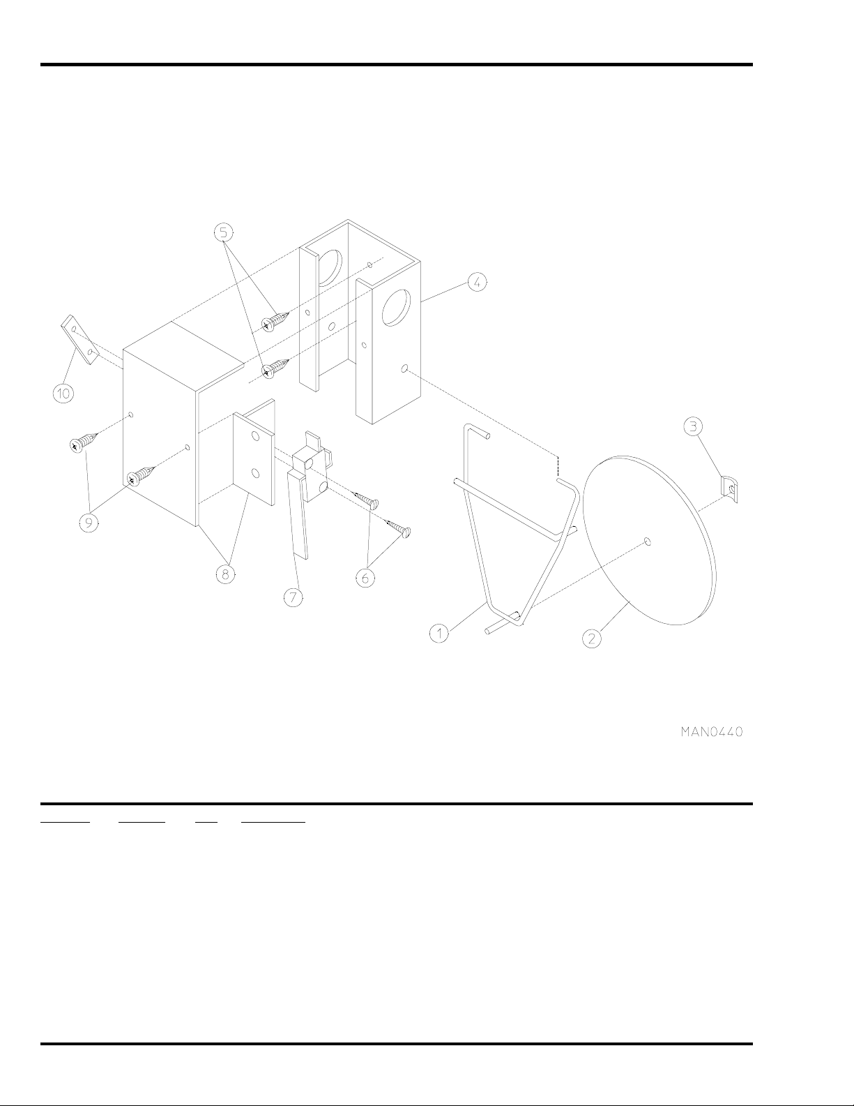
Sail Switch Assembly
Illus. No. Part No. Qty. Description
1 105500 1 Sail Switch Actuator Rod
2 319202 1 Sail Switch Damper (flat)
3 154002 1 1/8” Push-On Fastener
4 802800 1 Sail Switch Box with Cover and Bracket ONLY
802801 1 Sail Switch Box Assembly Complete
(includes illus. nos. 1 through 4 and 6 through 10)
5 150300 2 #10 x 1/2” Hex Washer TEK Screw
6 150303 2 #4 x 3/4” Pan Head “A” Machine Screw
7 122200 1 Sail Switch ONLY
8 802799 1 Sail Switch Box Cover and Bracket
9 150415 2 #10-16 x 1/2” Phillips Round Head Crimptite Screw
10 154004 1 Twin Speed Nut
28 American Dryer Corporation 450126- 8
Page 29

Microprocessor Reversing Control Box Assembly
Illus. No. Part No. Qty. Description
1 150301 6 #8-18 x 7/16” Phillips Pan Head TEK Screw
2 322815 1 Control Box Cover Plate (8-1/2” x 15-1/2”)
(for models mfd. as of January 4, 1993)
322808 1 Control Box Cover Plate (8-1/2” x 12”)
(for models mfd. prior to January 4, 1993)
3 137060 1 Arc Suppressor Board (3)
4 137013 4 Nylon Standoff
5 153002 1 5/16” Lock Washer
6 152004 1 5/16-18 Hex Nut
7 150108 4 #8-32 x 1/2” Pan Head Machine Screw
8 120704 1 3-Position Power Distribution Block
9 132445 1 Impellor (Fan / Blower) Contactor
10 322816 1 Contactor Mounting Panel (7” x 15-1/2”)
(for models mfd. as of January 4, 1993)
322807 1 Contactor Mounting Panel (7” x 10-1/2”)
(for models mfd. prior to January 4, 1993)
11 151001 4 #8-32 Pal Nut
12 150108 4 #8-32 x 1/2” Pan Head Machine Screw
13 132431 1 Reversing Contactor – 24 VAC
132432 1 Contactor Replacement Coil – 24 VAC
14 151001 4 #8-32 Pal Nut
15 132023 1 208-240 Volt Step Down Transformer – 24 VAC
132059 1 380 Volt Step Down Transformer – 24 VAC
132062 1 416 Volt Step Down Transformer – 24 VAC
132053 1 460 / 480 Volt Step Down Transformer – 24 VAC
16 150300 2 #10 x 1/2” Hex Washer TEK Screw
450126-8 www.amdry.com 29
Page 30

Timer Reversing Control Box Assembly
Illus. No. Part No. Qty. Description
1 150301 6 #8-18 x 7/16” Phillips Pan Head TEK Screw
2 322815 1 Control Box Cover Plate (8-1/2” x 15-1/2”)
(for models mfd. as of January 4, 1993)
322808 1 Control Box Cover Plate (8-1/2” x 12”)
(for models mfd. prior to January 4, 1993)
3 132198 1 Reversing Timer (50/60 Hz) – 24 VAC
4 150108 2 #8-32 x 1/2” Pan Head Machine Screw
5 153002 1 5/16” Lock Washer
6 152004 1 5/16-18 Hex Nut
7 150108 4 #8-32 x 1/2” Pan Head Machine Screw
8 120704 1 3-Position Power Distribution Block
9 132445 1 Impellor (Fan / Blower) Contactor
10 322816 1 Contactor Mounting Panel (7” x 15-1/2”)
(for models mfd. as of January 4, 1993)
322807 1 Contactor Mounting Panel (7” x 10-1/2”)
(for models mfd. prior to January 4, 1993)
11 151001 4 #8-32 Pal Nut
12 150108 4 #8-32 x 1/2” Pan Head Machine Screw
13 132431 1 Reversing Contactor – 24 VAC
132432 1 Contactor Replacement Coil – 24 VAC
14 151001 4 #8-32 Pal Nut
15 132023 1 208-240 Volt Step Down Transformer – 24 VAC
132059 1 380 Volt Step Down Transformer – 24 VAC
132062 1 416 Volt Step Down Transformer – 24 VAC
132053 1 460 / 480 Volt Step Down Transformer – 24 VAC
16 150300 2 #10 x 1/2” Hex Washer TEK Screw
30 American Dryer Corporation 450126- 8
Page 31

Back Guard Assembly
Illus. No. Part No. Qty. Description
1 820908 1 Back Guard Assembly (for Gas Models)
820978 1 Back Guard Assembly (for Steam Models)
2 152004 4 3/8-16 Hex Nut
3 153002 4 3/8” Lock Washer
4 153001 4 3/8” Flat Washer
5 322815 1 Control Box Cover Plate (8-1/2” x 15-1/2”)
(for models mfd. as of January 4, 1993)
322808 1 Control Box Cover Plate (8-1/2” x 12”)
(for models mfd. prior to January 4, 1993)
450126-8 www.amdry.com 31
Page 32

Additional Parts Available
Part No. Description
112027 “Water Washed Fabrics” Label
112040 “Lint Compartment” Label
112041 “Caution – Exhausted” Label
112534 “Phase 5 OPL Program Location Summary” Label
117505 Aluminum Duct Tape (sold by the foot)
120100 3/8” Straight (BX) Connector
120300 3/8” x 45° (BX) Connector
120400 3/8” Red Jacket (BX) Insulator
120500 3/8” Jiffy Clip (BX Retainer Clip)
120600 3/8” Greenfield (BX)
120800 1/4” In-Line Connector
120802 Red Butt Connector
120902 #74B Wire Nut
120903 Crimp-On Wire Nut
121014 1/4” Insulated (female) Terminal
121499 4” Harness Tie
121500 7” Harness Tie
121503 Harness Tie Mounting Clip
122804 Manometer (water column test gauge)
404500 Almond Brush-In-Cap Bottle Touch-Up Paint
404502 White Brush-In-Cap Bottle Touch-Up Paint
404506 Almond “B” Brush-In-Cap Bottle Touch-Up Paint
404507 Cornflower Blue Brush-In-Cap Bottle Touch-Up Paint
32 American Dryer Corporation 450126- 8
Page 33

Notes
450126-8 www.amdry.com 33
Page 34

ADC Part No. 450126 8 - 12/15/08 - 0
 Loading...