

Page 1

Fiber Distribution Terminal
ACE-142S/142V Cabinet
User Manual
ADCP-96-015
Issue 1
July 2004
19603-A
1290491 Rev A
Page 2

ADCP-96-015 • Issue 1 • July 2004 • Preface
COPYRIGHT
© 2004, ADC Telecommunications, Inc.
All Rights Reserved
Printed in the U.S.A.
REVISION HISTORY
ISSUE DATE REASON FOR CHANGE
1 07/2004 Original release.
LIST OF CHANGES
The technical changes incorporat ed into this issue are lis ted below.
PAGE IDENTIFIER DESCRIPTION OF CHANGE
All Original release
TRADEMARK INFORMATION
ADC and ADC Telecommunications are regis tered trademarks of ADC Telecomm unications, Inc.
Telcordia is a registered trademark of Telcordi a Technologies, Inc.
DISCLAIMER OF LIABILITY
Contents herein are current as of the date of publication. ADC reserves the right to change the contents without prior notice. In no
event shall ADC be liable for any damages resulting from loss of data, loss of use, or loss of profits and ADC further
disclaims an y and all liability for indirec t, incidental, special, consequen tial or other similar dam ages. This discl aimer of
liability applies to all products, publications and services during and after the warranty period.
This publ ication may be verified at any time by contacting ADC’s Technical Assistance Cent er at 1-800-366-3891, ex tension 73475
(in U.S. A . or Canada) or 952-9 17-3475 (outside U.S.A. and Canada), or by e-mail to bcg_tac@adc. com .
Page ii
ADC Telecommunications, Inc.
P.O. Box 1101, Minneapolis, Minnesota 55440-1101
In U.S.A. and Canada: 1-800-366-3891
Outside U.S.A. and Canada: (952) 938-8080
Fax: (952) 917-1717
Page 3

TABLE OF CONTENTS
TABLE OF CONTENTS
Content Page
ABOUT THIS MANUAL . . . . . . . . . . . . . . . . . . . . . . . . . . . . . . . . . . . . . . . . . . . . . . . . . . . . . . . . . . . . . . . . . . . . . . . . . v
Related Publications . . . . . . . . . . . . . . . . . . . . . . . . . . . . . . . . . . . . . . . . . . . . . . . . . . . . . . . . . . . . . . . . . . . . . . . . . . v
ADMONISHMENTS . . . . . . . . . . . . . . . . . . . . . . . . . . . . . . . . . . . . . . . . . . . . . . . . . . . . . . . . . . . . . . . . . . . . . . . . . . . v
GENERAL SAFETY PRECAUTIONS . . . . . . . . . . . . . . . . . . . . . . . . . . . . . . . . . . . . . . . . . . . . . . . . . . . . . . . . . . . . . . . . . v
STANDARDS CERTIFICATION . . . . . . . . . . . . . . . . . . . . . . . . . . . . . . . . . . . . . . . . . . . . . . . . . . . . . . . . . . . . . . . . . . . . vi
LIST OF ACRONYMS AND ABBREVIATIONS . . . . . . . . . . . . . . . . . . . . . . . . . . . . . . . . . . . . . . . . . . . . . . . . . . . . . . . . . . . vi
1 DESCRIPTION . . . . . . . . . . . . . . . . . . . . . . . . . . . . . . . . . . . . . . . . . . . . . . . . . . . . . . . . . . . . . . . . . . . . . . . . . . 1
1.1 ACE-142S/142V Cabinet . . . . . . . . . . . . . . . . . . . . . . . . . . . . . . . . . . . . . . . . . . . . . . . . . . . . . . . . . . . . . 1
1.2 Accessories and Replacement Parts. . . . . . . . . . . . . . . . . . . . . . . . . . . . . . . . . . . . . . . . . . . . . . . . . . . . . 4
2 BEFORE STARTING THE INSTALLATION . . . . . . . . . . . . . . . . . . . . . . . . . . . . . . . . . . . . . . . . . . . . . . . . . . . . . . . . 5
2.1 Installation Overview . . . . . . . . . . . . . . . . . . . . . . . . . . . . . . . . . . . . . . . . . . . . . . . . . . . . . . . . . . . . . . . 5
2.2 Unpacking and Inspection. . . . . . . . . . . . . . . . . . . . . . . . . . . . . . . . . . . . . . . . . . . . . . . . . . . . . . . . . . . . 5
2.3 Cabinet Installation Hardware . . . . . . . . . . . . . . . . . . . . . . . . . . . . . . . . . . . . . . . . . . . . . . . . . . . . . . . . . 6
2.4 Tools and Materials Required for Installation . . . . . . . . . . . . . . . . . . . . . . . . . . . . . . . . . . . . . . . . . . . . . . 6
2.5 Cabinet Mounting . . . . . . . . . . . . . . . . . . . . . . . . . . . . . . . . . . . . . . . . . . . . . . . . . . . . . . . . . . . . . . . . . 7
3 MOUNTING THE CABINET ON A FIBERGLASS MOUNTING SLEEVE . . . . . . . . . . . . . . . . . . . . . . . . . . . . . . . . . . . . . . 8
3.1 Installation Recommendations . . . . . . . . . . . . . . . . . . . . . . . . . . . . . . . . . . . . . . . . . . . . . . . . . . . . . . . . 8
3.2 Excavation . . . . . . . . . . . . . . . . . . . . . . . . . . . . . . . . . . . . . . . . . . . . . . . . . . . . . . . . . . . . . . . . . . . . . . 9
3.3 Placement of the FMS . . . . . . . . . . . . . . . . . . . . . . . . . . . . . . . . . . . . . . . . . . . . . . . . . . . . . . . . . . . . . . 9
3.4 Cable Conduit Installation. . . . . . . . . . . . . . . . . . . . . . . . . . . . . . . . . . . . . . . . . . . . . . . . . . . . . . . . . . . 10
3.5 Grounding System Installation. . . . . . . . . . . . . . . . . . . . . . . . . . . . . . . . . . . . . . . . . . . . . . . . . . . . . . . . 10
3.6 Back Fill. . . . . . . . . . . . . . . . . . . . . . . . . . . . . . . . . . . . . . . . . . . . . . . . . . . . . . . . . . . . . . . . . . . . . . . 10
3.7 Mounting the Cabinet on the FMS-20000. . . . . . . . . . . . . . . . . . . . . . . . . . . . . . . . . . . . . . . . . . . . . . . . . 10
4 MOUNTING THE CABINET ON A CONCRETE PAD . . . . . . . . . . . . . . . . . . . . . . . . . . . . . . . . . . . . . . . . . . . . . . . . . 15
4.1 Installation Recommendations . . . . . . . . . . . . . . . . . . . . . . . . . . . . . . . . . . . . . . . . . . . . . . . . . . . . . . . 15
4.2 Cable Conduit Installation. . . . . . . . . . . . . . . . . . . . . . . . . . . . . . . . . . . . . . . . . . . . . . . . . . . . . . . . . . . 15
4.3 Base Installation . . . . . . . . . . . . . . . . . . . . . . . . . . . . . . . . . . . . . . . . . . . . . . . . . . . . . . . . . . . . . . . . . 15
4.4 Concrete Pad Construction . . . . . . . . . . . . . . . . . . . . . . . . . . . . . . . . . . . . . . . . . . . . . . . . . . . . . . . . . . 17
4.5 Grounding System Installation. . . . . . . . . . . . . . . . . . . . . . . . . . . . . . . . . . . . . . . . . . . . . . . . . . . . . . . . 18
4.6 Mounting the Cabinet on the Concrete Pad . . . . . . . . . . . . . . . . . . . . . . . . . . . . . . . . . . . . . . . . . . . . . . . 18
5 FEEDER CABLE INSTALLATION AND SPLICING . . . . . . . . . . . . . . . . . . . . . . . . . . . . . . . . . . . . . . . . . . . . . . . . . . 22
5.1 Bottom Cover Removal. . . . . . . . . . . . . . . . . . . . . . . . . . . . . . . . . . . . . . . . . . . . . . . . . . . . . . . . . . . . . 22
5.2 Cabinet Grounding Wire Connection . . . . . . . . . . . . . . . . . . . . . . . . . . . . . . . . . . . . . . . . . . . . . . . . . . . . 22
5.3 Feeder Cable Installation . . . . . . . . . . . . . . . . . . . . . . . . . . . . . . . . . . . . . . . . . . . . . . . . . . . . . . . . . . . 23
5.4 Feeder Cable and Splitter Input Fiber Splicing . . . . . . . . . . . . . . . . . . . . . . . . . . . . . . . . . . . . . . . . . . . . . 26
6 DISTRIBUTION CABLE INSTALLATION AND SPLICING. . . . . . . . . . . . . . . . . . . . . . . . . . . . . . . . . . . . . . . . . . . . . . 29
6.1 Distribution Cable Installation . . . . . . . . . . . . . . . . . . . . . . . . . . . . . . . . . . . . . . . . . . . . . . . . . . . . . . . . 29
6.2 Bottom Cover Installation . . . . . . . . . . . . . . . . . . . . . . . . . . . . . . . . . . . . . . . . . . . . . . . . . . . . . . . . . . . 32
6.3 Distribution Cable and Connector Panel Pigtail Splicing . . . . . . . . . . . . . . . . . . . . . . . . . . . . . . . . . . . . . . 33
7 GUIDELINES FOR USING ROUND SPLICE TRAYS . . . . . . . . . . . . . . . . . . . . . . . . . . . . . . . . . . . . . . . . . . . . . . . . . 37
8 PRE-INSTALLED DISTRIBUTION CABLE CONFIGURATION . . . . . . . . . . . . . . . . . . . . . . . . . . . . . . . . . . . . . . . . . . . 41
ADCP-96-015 • Issue 1 • July 2004 • Preface
© 2004, ADC Telecommunications , Inc.
Page iii
Page 4

ADCP-96-015 • Issue 1 • July 2004 • Preface
TABLE OF CONTENTS
TABLE OF CONTENTS
Content Page
9 CONNECTOR PANEL INSTALLATION . . . . . . . . . . . . . . . . . . . . . . . . . . . . . . . . . . . . . . . . . . . . . . . . . . . . . . . . . 42
10 SPLITTER MODULE INSTALLATION . . . . . . . . . . . . . . . . . . . . . . . . . . . . . . . . . . . . . . . . . . . . . . . . . . . . . . . . . . 43
11 ROUTING AND CONNECTING THE SPLITTER OUTPUT FIBERS . . . . . . . . . . . . . . . . . . . . . . . . . . . . . . . . . . . . . . . . 45
11.1 Storing The Splitter Output Fibers . . . . . . . . . . . . . . . . . . . . . . . . . . . . . . . . . . . . . . . . . . . . . . . . . . . . . 45
11.2 Enabling Service To a Subscriber . . . . . . . . . . . . . . . . . . . . . . . . . . . . . . . . . . . . . . . . . . . . . . . . . . . . . 46
12 MAINTENANCE AND REPAIR PROCEDURES . . . . . . . . . . . . . . . . . . . . . . . . . . . . . . . . . . . . . . . . . . . . . . . . . . . . 47
12.1 Painting. . . . . . . . . . . . . . . . . . . . . . . . . . . . . . . . . . . . . . . . . . . . . . . . . . . . . . . . . . . . . . . . . . . . . . . 47
12.2 Adapter Replacement . . . . . . . . . . . . . . . . . . . . . . . . . . . . . . . . . . . . . . . . . . . . . . . . . . . . . . . . . . . . . 47
12.3 Connector Replacement . . . . . . . . . . . . . . . . . . . . . . . . . . . . . . . . . . . . . . . . . . . . . . . . . . . . . . . . . . . . 48
13 CUSTOMER INFORMATION AND ASSISTANCE. . . . . . . . . . . . . . . . . . . . . . . . . . . . . . . . . . . . . . . . . . . . . . . . . . . 49
_________________________________________________________________________________________________________
Page iv
© 2004, ADC Telecommunications , Inc.
Page 5

ABOUT THIS MANUAL
This publication provides a complete description of the Fiber Distribution Terminal (FDT)
ACE-142 S/142V Cabinet. Also included are procedures for mounting the cabine t, installing and
splicing the feeder and distribution cables, installing additional connector panels and splitter
modules, connecting the splitter output fibers to the distribution fibers, and replacing damaged
components.
RELATED PUBLICATIONS
Listed below are related manuals and their publication numbers. Copies of these publications
can be ordered by contacti ng the ADC T e chnical Assi stance Center at 1-800-366- 389, ext ension
73475 (in U.S.A. or Canada) or 1-952-917-3475 (outside U.S.A. and Canada).
Title ADCP Number
Round Splice Tra y Cable Routing Instructions 90-321
Optical Fiber Systems Cleaning and Mating Instructions 90-159
ADCP-96-015 • Issue 1 • July 2004 • Preface
ADMONISHMENTS
Important safety admonishments are used thr oughout this manual to warn of possible hazards to
persons or equipment. An admonishment identifies a possible hazard and then explains what
may happen if the hazard is not avoided. The admonishments — in the form of Dangers,
Warnings, and Cautions — must be followed at all times. These warnings are flagged by use of
the triangular alert icon (seen below) and are listed in descending order of severity of injury or
damage and likelihood of occurrence.
Danger: Danger is used to indicate the presence of a hazard that will cause severe personal
injury, death, or substantial property damage if the hazard is not avoided.
Warning: Warning is used to indicate the presence of a hazard that can cause s evere personal
injury, death, or substantial property damage if the hazard is not avoided.
Caution: Caution is used to indicate the presence of a hazard that will or can cause minor
personal injury or property damage if the hazard is not avoided.
GENERAL SAFETY PRECAUTIONS
Warning: Wet conditions increase the potential for receiving an electrical shock when
installing or using electrically-powered equipment. To prevent electrical shock, never install or
use electrical equipment in a wet locat ion or during a lightning storm.
© 2004, ADC Telecommunications , Inc.
Page v
Page 6

ADCP-96-015 • Issue A • June 2001 • Preface
Danger: Do not look into the ends of any optical fiber. Exposure to laser radiation may result.
Do not assume the laser power is turned-off or that the fiber is disconnected at the other end.
Danger: Use adequate lifting equipment when moving or installing Fiber Distribution Terminal
cabi n ets . Verify t ha t th e m ax im um l ift w eig ht rat ing of t he e qu ip m ent is su ffic ient t o h and le th e
weight of the cabinet.
Danger: Do not stand under a Fiber Distribution Terminal cabinet as it is being hoisted into
position for mounting. A failure of the lifting equipment or apparatus could result in serious
personal injury.
Warning: Before digging, check with all local utilities for the presence of buried cables or
pipes. Contact with underground cables or pipes, especially electric power cables and gas
service lines, could interrupt local utility service and cause serious personal injury and
extensive property damage.
STANDARDS CERTIFICATION
Telcordia: This equipment complies with the applicable sections of GR-2898-CORE (Issue 2,
December 1999)
LIST OF ACRONYMS AND ABBREVIATIONS
The acronyms and abbreviations used in this manual are detailed in the following list:
AWG American Wire Gauge
C Centigrade
F Fahrenheit
FDT Fiber Distribut ion Terminal
FMS Fiberglass Mounting Sleeve
FTTP Fiber To The Premises
OSP Outsid e Plan t
PMF Pad Mount Frame
Page vi
© 2004, ADC Telecommunications , Inc.
Page 7
1 DESCRIPTION
This section provides a description of the ACE-142S/142V cabinet plus specifications. Also
included is a listing of the various acc es s orie s and kits .
1.1 ACE-142S/142V Cabinet
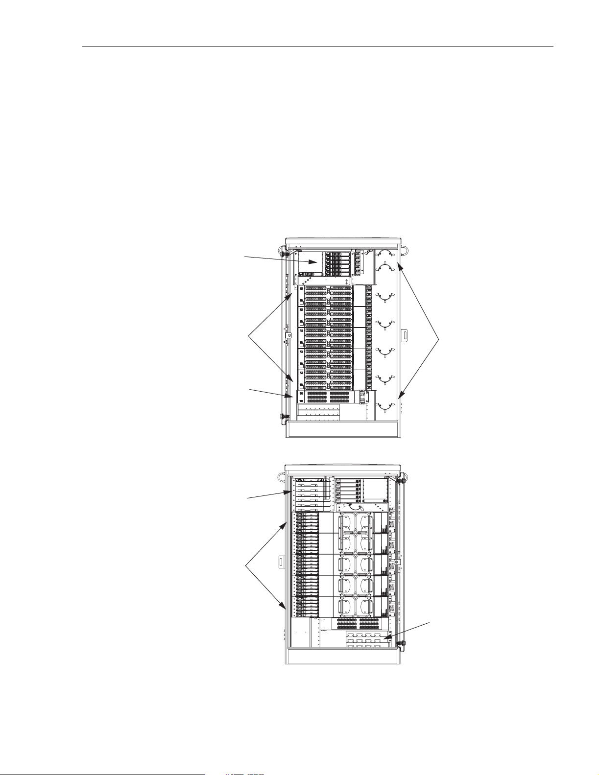
The ACE-142S/142V cabinet is a secure, above-ground, outdoor fiber optic distribution cabinet
that is designed to hold the splice trays, splitters, connector panels, and connector storage panel
required for various Fiber To The Premises (FTTP) applications. A typical ACE-142S/142V
cabinet (with split ter modules and connector panels installed) is shown in Figure 1.
SPLITTER
MODULES
ADCP-96-015 • Issue 1 • July 2004
CONNECTOR
PANELS
CONNECTOR
STORAGE PANEL
(PARKING LOT)
FEEDER CABLE
SPLICE TRAYS
DISTRIBUTION
CABLE
SPLICE TRAYS
RADIUS LIMITERS
FOR SPLITTER
OUTPUT FIBER
SLACK STORAGE
FRONT
REAR
Figure 1. Typical ACE-142S/142V Cabinet
CABLE
CLAMPS
19620-A
Page 1
© 2004, ADC Telecommunications , Inc.
Page 8

ADCP-96-015 • Issue 1 • July 2004
The outsid e plant (OSP) fe eder and dist ribution cables e nter the cabinet from the botto m rear
side. Clamps are provided for securing each cable to the inside of the cabinet. The bottom of the
cabinet is e nclose d with a t wo-piec e removable m oistu re ba rrier. The cable ent ry/exit hol es ar e
fitted with grommets to resist the entry of dust and moisture. On an optional basis, the cabinet
may be ordered with the distribution cables pre-installed.
The ACE-142S/142V cabinet is constructed of heavy gauge aluminum and is coated with an
almond-colored finish. The cabinet doors are equipped with tamper-resistant latches with hasps
for padlocks , stainless steel hinges, and door catches to prevent accidental closing. Acc ess to the
cabinet requ ires a
the sides of the cabinet to allow use of hoisting equipment. A grounding bus is provided within
the cabinet for grounding the cabinet and cables per local practice.
The ACE-142S/142V cabinet can accommodate up to thirty-seven round splice trays, up to
twelve 1x8 or 1x32 splitter modules, and five 72-position c onnector panels equipped with APC/
SC adapters. Seven splice tray slots are provided for feeder cable splices. Thirty splice tray slots
are provided for distribution cable splices. The ACE-142S/142V cabinet is equipped with two
doors that provide fro nt and rear access to the opti cal components. Th e specifications for the
ACE-142S/142V cab i net are p rovid ed in Table 1.
216B key tool (accessory) to operate the latches. Lifting eyes are attached to
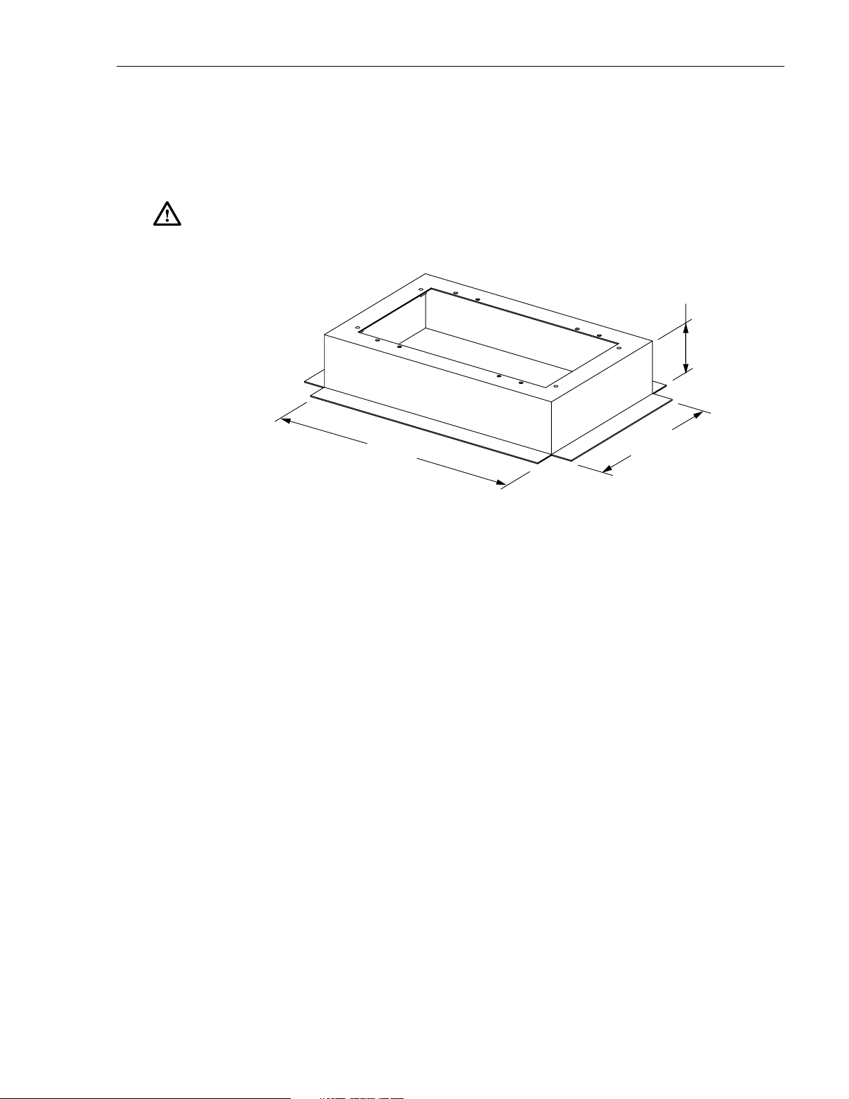
Table 1. ACE-142S/142V Cabinet Specifications
PARAMETER SPECIFICATION
Cabinet
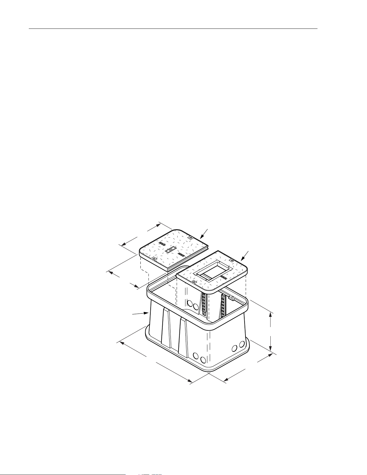
Dimensions (W x D x H) – See Figure 2 27.5 x 19.7 x 47.5 inches (699 x 500.4 x 1206.5 mm)
Weight (fully loaded) 210 lbs (95.3 kg)
Certification (Pending) GR-2898-CORE (Issue 2, December 1999)
Distribution ports 360 (with 5 connector panels installed)
Distribution port connectors APC/SC
Splitter module capacity (1x8 or 1x32) 12
Splice tray capa city (round)
Feeder cable
Distribution cable
Total feeder cable splices 84 (7 splice trays with 12 spli ces per tray)
Total distrib ution cable splices 360 (30 splice trays with 12 splices per tray)
Splitter Modules
Splitter module output pigtails 2 mm with APC/SC connectors
Splitter module input pigtail 2 mm
Test bandpass 1260–1360 nm
7
30
1480–1500 nm
1550–1560 nm
Overall bandpass 1260–1625 nm
Page 2
© 2004, ADC Telecommunications , Inc.
Page 9

Table 1. ACE-142S/142V Cabinet Specifications, continued
PARAMETER SPECIFICATION
Insertion loss at test bandpass
1x8 standard APC/SC
1x32 standard APC/SC
11.1 dB Maximum (Including connector)
17.8 dB Maximum (Including connector)
Return loss at test ba ndpass
1x8 standard APC/SC
1x32 standard APC/SC
30.8 IN.
(78.2 CM)
>55 dB
>55 dB
ADCP-96-015 • Issue 1 • July 2004
47.5 IN.
(120.7 CM)
27.3 IN.
(69.3 CM)
Figure 2. ACE-142S/142V Cabinet Dimensions
© 2004, ADC Telecommunications , Inc.
19.7 IN.
(50.1 CM)
19606-A
Page 3
Page 10

ADCP-96-015 • Issue 1 • July 2004
1.2 Accessories and Replacement Parts
Refer to Table 2 and Table 3 for a listing o f the various acces sories and replacem ent parts th at
are available for the ACE-142S/142V cabinet.
Table 2. ACE-142S/142V Cabinet Accessories and Replacement Parts
DESCRIPTION CATALOG NUMBER
Mounting Kits
Fiberglass Mounting Sleeve (se e Figure 3 for dimensions) FMS-20000
FMS sleeve cover FCVR-200CVR
FMS adapter cover FCVR-200ACE 1000
Concrete pad mount frame (PMF) kit ACE-100PMF
Ground spacer ACE-ACCSPCRO6S-102
Cable Hardware Kit s
Blocking kit, loose buffer tube FBK-OSP002
Clamping kit OSP-CLPSST
Grounding kit, loose buffer tube
GND-STPKIT
Cable grommet kit ACE-ACC-CBLGRMT
Miscellaneous
OSP-216BKEY1
216B key tool (required to open cabinet door)
Splice wheel, HS FST-DRS12-HS
Splice wheel, mechanical FST-DRS12 - M T
Touch-up paint - Almond ACE-ACC-PTALMD
Filter replacement kit OSP-FLTRKIT1
Cleaning kit FPC-CLNKIT1
Straight retainer kit FBA-ASCZ-S/R
Table 3. ACE-142S/142V Cabinet Splitter Modules
DESCRIPTION OF SPLITTER MODULE CATALOG NUMBER
1x8, standard, APC/SC FPS-SPK1AOJ
1x32, standard, APC/SC FPS-SPK1JOJ
Page 4
© 2004, ADC Telecommunications , Inc.
Page 11

2 BEFORE STARTING THE INSTALLATION
This section provides general installation considerations, unpacking and inspection procedures,
and lists the tools and materia ls required for cabinet installation.
2.1 Installation Overview
Installation of the ACE-142S/142V cabinet involves the fo llowing main tasks:
Installing a Support Base–The cabinet must be mounted on a suitable support base. The
following two mounting options are available:
• Fiberglass M ounti ng Sl eeve (FM S)–The FMS provides a stable mounting platform plus
storage space under the cabinet for OSP cable slack. The FMS may also be used as a
splicing va ult for the OSP feeder and distribution cables.
• Poured Concrete Pad–Concrete slab with Pad Mounting Frame (PMF). The PMF
provides a stainless-steel frame for mounting the cabinet. The PMF ensures that the
cabinet will be securel y anchor ed to the concrete slab.
ADCP-96-015 • Issue 1 • July 2004
Mounting the Cabinet–After the support base is installed, the cabinet is secured to the support
base.
Feeder and Di stribution Ca ble Installa tion–The cabinet OSP feeder and distribution cables
are routed into the cabinet and spliced.
Connector Panel Installation-Additional connector panels are installed in the cabinet if
needed.
Spli tter in stal la t i o n–Additional splitters are installed in the cabinet if needed.
2.2 Unpacking and Inspection
This section provides instructions for opening the shipping boxes, verifying that all parts have
been recei ved, and verifying that no shipping damag e has occurred.
Use the following pr ocedure to unpack and inspect the cabinet and all accessorie s:
1. Open the shi pping carton(s) and carefully unpack the cabinet and any accessories from the
protective packing material.
2. Open the cabinet doors (requires 216B key tool) and check for broken or missing parts. If
there are damages, contact ADC (see Section 13) for an RMA (Return Material
Authorization) and to reorder if replacement is required.
© 2004, ADC Telecommunications , Inc.
Page 5
Page 12

ADCP-96-015 • Issue 1 • July 2004
2.3 Cabinet Installation Hardware
The cabi net i s s hipp ed with fastener s (see Table 4) for securing the ACE-142S/142V cabinet to
the FM S or the PMF.
Table 4. Cabinet Installation Fasteners
ITEM QUANTITY
3/8 x 1-inch hex head capscrews 4
3/8-in ch fl at wa sh er s 4
3/8-i n ch lo ck wa sh er s 4
2.4 Tools and Materials Required for Installation
The followin g tools and materials are required for cabinet insta llation:
All Installations
• 9/16-inch w rench
•Hammer
• Wire cutter
• Utility knife
• Screwdriver (flat blade)
• Tape measure
•Pen or marker
• 216B key tool (required to open cabinet door)
• Padlock (optional)
• Grounding system, copper wire, and grounding clamp (per local requirements)
• Splicing equipment for splicing OSP feeder and distribution cables
• Lifting equipment f or hoisting the cabinet into position for mounting
Fiberglass M ounting Sleeve Instal lat ion s
• Fiberglass Mounting Sleeve (FMS), FMS sleeve cover, FMS adapter cover (see Table 2)
• Excavation and earth moving equipment
• Stone aggre gate
• Tamping equipment
•Level
• Hole saw and drill (use to cut holes for cable conduit if pre-drilled holes are not usable)
• Landscaping equipm ent and site restoration supplies
Page 6
© 2004, ADC Telecommunications , Inc.
Page 13

Concrete Pad Installations
• Pad Mount Frame kit for ACE-142
• Excavation and earth moving equipment
• Concrete finishing equipment
• Approximately 10 cu. ft. concrete
• Sand or gravel
• Tamping equipment
• 2 x 6 inch framing lumber
• 1 x 4 inch woo den stakes (4)
• Nails and construct ion screws
• Utility wire (to secure PMF during installation)
•Saw
• Drill with screwdriver bits
• Square
ADCP-96-015 • Issue 1 • July 2004
•Level
• Landscaping equipm ent and site restoration supplies
2.5 Cabinet Mounting
The next two sections provides instructions for mounting the cabinet on either a fiberglass
mounting sleeve or concrete pad. Use whichever procedure is appropriate for the inst allation.
© 2004, ADC Telecommunications , Inc.
Page 7
Page 14
ADCP-96-015 • Issue 1 • July 2004
3 MOUNTING THE CABINET ON A FIBERGLASS MOUNTING SLEEVE
The FMS-20000, shown in Figure3, is a fiberglass and polymer concrete sleeve that may be
used to support the cabinet at ground level. The FMS may also be used as a splicing vault. Four
vertical racks are molded into the sides of the FMS to accommodate removable rungs (not
provided). The rungs provide support for splice cases or OSP cable storage.
3.1 Installation Recommendations
The site chosen for the installation must conform to all local codes and any permits required
must be obtained prior to the start of installation. The location must be accessible and provide
adequate parking for worker and vehicle safety.
The installed cabinet must not create a visual or physical obstruction to vehicular or pedestrian
traffic. Ensure that there is sufficient space on all sides to facilitate cabinet installation.
Depending on the landscaping requirements, the top surface of the mounting sleeve may be
located from 0 to 4 inches (10.2 cm) above the surrounding grade.
29.81 IN.
FIBERGLASS
MOUNTING
SLEEVE (FMS)
FMS COVER
38.5 IN.
FMS ADAPTER
COVER
30.0 IN.
68.0 IN.
47.0 IN.
19161-B
Page 8
© 2004, ADC Telecommunications , Inc.
Figure 3. Fiberglass Mounting Sleeve (FMS-20000)
Page 15
3.2 Excavation
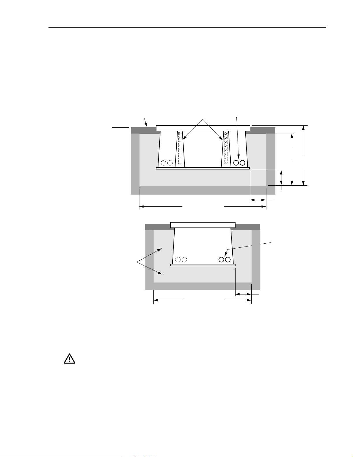
The excavation must be large enough to provide a fill base that will maintain stability for the
FMS and the cabinet mounted on it. There must be room for 12 inches (30.5 cm) of fill below
and on each side of the FMS. The excavation dimensions for the FMS 20000 are shown in
Figure 4. Excavate a rectangular hole for the FMS.
ADCP-96-015 • Issue 1 • July 2004
TOPSOIL OR
DECORATIVE ROCK
GRADE
TAMP AGGREGATE AS
HOLE IS FILLED
VERTICAL RACKS
FOR MANHOLE
CABLE SUPPORT BARS.
SIDE VIEW
STONE
AGGREGATE FILL
COMPACTED SOIL
92 IN (234 CM)
END VIEW
STONE
AGGREGATE FILL
CONDUIT
ENTRANCE
HOLES
38 IN
(96.5 IN)
42 IN
(106.7 CM)
12 IN
(30.5 CM)
CONDUIT
ENTRANCE
HOLES
3.3 Placement of the FMS
Danger: Use adequate lifti ng equi pme nt wh en ins tal li ng the FMS. Do not s tan d in th e hole w hil e
placing the FMS in position. An unexpected shift of the FMS could result in personal injury.
Use the following procedures to place the FMS into the excavation.
1. Fill the bottom of the hole with stone aggregate, tamping it as it is filled to build a 12 inch
(30.5 cm) layer with a level surface. The stone aggregate will provide a stable base to
support the FMS.
COMPACTED SOIL
71 IN (180 CM)
(30.5 CM)
Figure 4. Excavation Recommendations for FMS-20000
© 2004, ADC Telecommunications , Inc.
12 IN
19090-B
Page 9
Page 16

ADCP-96-015 • Issue 1 • July 2004
Note: Use crushed rock 3/8-inch or less in size mixed with stone dust (per local practice)
to fill the hole. The name of the material may differ in different geographical areas.
Possible names are Class 5, stone dust, aughts (0s) and ones (1s), or stone aggregate
2. Use appropriate lifting equipment to place the FMS into the center of the hole. Lifting
loops are provided on eit her side of the FMS for attaching a sling or chain.
3. Use a carpenter’s level to verify that the FMS is level. If it is necessary to add or remove
fill for leveling, tamp any added fill to maintain the base stability.
3.4 Cable Conduit Installation
Select the conduit entrance hole(s) for the OSP feeder and distribution cables. Refer to Figure 4
for the location of the holes. If necessary, additional conduit entrance holes may be cut using a
power drill and hole saw. Place and route the conduit into the entrance hole(s). If preferred, the
FMS may be installed without conduit . OSP cables may be routed into the FMS at any point tha t
is convenient. Cut the cable entrance hole to match the size of the cable.
3.5 Grounding System Installation
Install a grounding system (not provi ded ) that meets all loc al electr ical codes. C heck local codes
for grounding system installation, use of clamps, wire size, and any other grounding
requirements. Typically, #6 AWG copper wire is used for the grounding wire. Install the
grounding syste m inside the FMS where it will not interfere with the conduit or cables. Connect
the grounding wire to the grounding system. Leave sufficient slack in the grounding wire to
allow it to be routed into the cabinet after the cabinet is mounted on the sleeve.
3.6 Back Fill
If installing conduit, hand shovel stone aggregate under the conduit to avoid damage from the
power tamper. Complete the back fill as follows:
1. Add stone aggregate evenly around the FMS and tamp. Fill to approximately 6 inches
(15.2 cm) from the top of the excavation.
2. Complete the back-fill with crushed rock or topsoil depending on the landscaping
requirements. The top surface of the mounting sleeve may be located from 0 to 4 inches
(10.2 cm) above the surrounding grade (see Figure 4).
3.7 Mounting the Cabinet on the FMS-20000
The following sections provide instructions for mounting the ACE-142S/142V cabinet on the
FMS-20000. With the ACE-142S cabinet, the distribution cables must be installed after the
cabinet is mounted. With the ACE-142V cabinet, the distribution cables are pre-installed in the
cabinet by the factory. If mounting an ACE-142S cabinet, refer to Section 3.7.1 for the cabinet
mounting procedure. If mounting an ACE-142V cabinet with pre-installed distribution cables,
refer to Section 3.7.2 for t he cabinet mounting proce dur e. Use the 216B key tool to un-latch and
latch the cabinet doors as need ed during the mounting process.
Page 10
© 2004, ADC Telecommunications , Inc.
Page 17
ADCP-96-015 • Issue 1 • July 2004
Warning: Use appropriate lifting equipment when moving or installing the cabinet. Do not
stand under a cabinet as it is being hoisted into position for mounting. A failure of the lifting
equipment could result in serious personal injury.
3.7.1 Mounting the ACE-142S Cabinet on the FMS-20000
Use the following procedure to mount an ACE-142 cabinet on the FMS-20000:
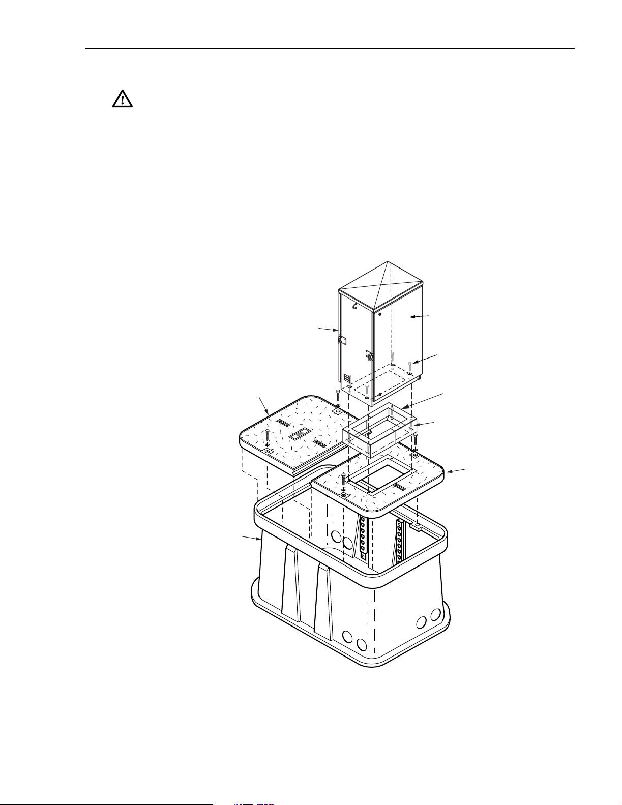
1. Install the FMS adapter cover onto the FMS and secu re using the t wo capscrews and flat
washers provided with the cover as shown in Figure 5. Tighten each capscrews securely.
ACE-142S
CABINET
FRONT
(REAR)
FMS SLEEVE
FMS-20000
COVER
HEX BOLTS, FLAT
WASHERS, AND
NUTS (4 PLACES)
GROUND SPACER
(ACCESSORY)
CAPSCREWS, LOCK
WASHERS, AND FLAT
WASHERS (4 PLACES)
FMS ADAPTER
COVER
19607-B
Figure 5. Mounting the ACE-142S Cabinet on the FMS-20000
© 2004, ADC Telecommunications , Inc.
Page 11
Page 18

ADCP-96-015 • Issue 1 • July 2004
2. If a ground spacer (accessory) will not be installed, proceed to step 7. If a ground spacer
will be installed, align the ends of the left ground spacer section with the ends of the right
ground spacer section and then press the two sections together.
3. Place the assembl ed ground spacer in position for mounting on the adapter cov er.
4. Align the mounting holes in the ground spacer with the mounting holes in the adapter
cover.
5. Secure the ground spacer to the adapter cover using the f our capscrews, four lock washers,
and four flat washers provided with the cabinet. Tighten all capscrews securely.
6. Open the rear door of the cabinet and remove the back section of the cabinet bottom cover
as described in Section 5.1. Then return to step 7 of this procedure to finish mounting the
cabinet.
7. Using appropriate lifting equipment, hold the cabinet in position for mounting onto the
ground spacer or adapter cover.
8. Lo wer the cabinet onto the groun d spa cer or adapter cover and align the mounting hole s in
the bottom of the cabinet with the holes in the spacer or cover.
9. If the installation includes a ground spacer, secure the cabinet to the spacer using the four
hex bolts, four flat washers and four nuts provided with the spacer. If the installation does
not include a ground spacer, secure the cabinet to the adapter cover using the four hex
bolts, lock flat washers, and four flat washers provided with the cabinet. Tighten all
fasteners secur ely.
10. If the FMS will be used as a splicing vault for the OSP feeder and distribution cables,
install the requi red spli ce en clo su re.
11. Install the FMS sleeve cover onto the FMS and secure using the two capscrews and
washers provided with the cover. Tighten both capscrews securely.
3.7.2 Mounting The ACE-142V Cabinet on the FMS-20000
Use the following pr ocedure to mount the ACE-142V cabinet on the FMS-20000:
1. Mount the FMS adapter cover on the FMS and secure using the two capscrews and flat
washers provided with the cover as shown in Figure 6. Tighten each cap screw securely.
2. If a ground spacer (accessory) will not be installed, proceed to step 7. If a ground spacer
will be installed, align the ends of the left ground spacer section with the ends of the right
ground spacer section and then press the two sections together.
3. Place the assembl ed ground spacer in position for mounting on the adapter cov er.
4. Align the mounting holes in the ground spacer with the mounting holes in the adapter
cover.
5. Secure the ground spacer to the adapter cover using the f our capscrews, four lock washers,
and four flat washers provided with the cabinet. Tighten all capscrews securely.
6. Open the rear door of the cabinet and remove the back section of the cabinet bottom cover
as described in Section 5.1. Then return to step 7 of this procedure to finish mounting the
cabinet.
Page 12
© 2004, ADC Telecommunications , Inc.
Page 19

ACE-142V
CABINET
ADCP-96-015 • Issue 1 • July 2004
FMS SLEEVE
FMS-20000
COVER
FRONT SIDE
REAR SIDE
HEX BOLTS, FLAT
WASHERS, AND
NUTS (4 PLACES)
GROUND SPACER
(ACCESSORY)
CAPSCREWS, LOCK
WASHERS, AND FLAT
WASHERS (4 PLACES)
FMS ADAPTER
COVER
19814-A
Figure 6. Mounting The ACE-142V Cabinet on the FMS-20000
7. Using appropriate lifting equipment, hold the cabinet in position over the FMS-20000 so
the cabinet is suspended over the rectangular opening in the top of the ground spacer or
adapter cover.
8. Carefully route the distribution cables through the rectangular opening in the ground
spacer or adapter cover and into the FMS-20000.
Note: The cables are coiled on spools for shipment. On each spool is a label that lis ts each
fiber subunit within the cabl e and the connect or panels wh ere each subunit is term inated.
After the cable is unspooled, label each cable with the corresponding fiber subunit and
connector panel designa tions. In additi on, tag or label the stub end of each cabl e so that the
cable can be identif ie d after being routed to the splice enclosure.
9. Lo cate the ends of the c onduit sect ions that were installed in the bottom of the FMS-20000.
© 2004, ADC Telecommunications , Inc.
Page 13
Page 20

ADCP-96-015 • Issue 1 • July 2004
10. Feed each distribution cable into the appropriate conduit section and route to the splice
enclosure (not provided). An y excess cable slack may be stored in the bottom of the FMS.
Note: A separate splice enclosure (not provided) is required for splicing the cabinet OSP
distribution cables to the system OSP distribution cables. If preferred, the splice enclosure
for the distribution cables may be mounted within the FMS-20000.
11. Lo wer the cabinet onto the groun d spa cer or adapter cover and align the mounting hole s in
the bottom of the cabinet with the holes in the cover.
12. If the installation includes a ground spacer, secure the cabinet to the spacer using the four
hex bolts, four flat washers and four nuts provided with the spacer. If the installation does
not include a ground spacer, secure the cabinet to the adapter cover using the four
capscrews, four lock washe rs , a nd fou r fl at w as hers p r ovide d with t he cabinet. Tighten al l
fasteners secur ely.
13. Install the FMS sleeve cover onto the FMS and secure using the two capscrews and
washers provided with the cover. Tighten both capscrews securely.
Page 14
© 2004, ADC Telecommunications , Inc.
Page 21
4 MOUNTING THE CABINET ON A CONCRETE PAD
The Pad Mount Frame (PMF), shown in Figure 7, is a stainless steel frame that provides a
mounting base for the cabinet when installed in a concrete pad foundation.
Caution: Mounting the cabinet directly on a concrete pad may cause chemical corrosive action
to the cabinet. Use only the Pad Mount Frame (PMF) as a mounting base for the cabinet. Do
not use caulking compounds as a sealer between the cabinet and the PMF.
ADCP-96-015 • Issue 1 • July 2004
5.5 IN.
(14.0 CM)
4.1 Installation Recommendations
The site chosen for the installation must conform to all local codes and any permits required
must be obtained prior to the start of installation. The location must be accessible and provide
adequate parking for worker and vehicle safety. Situate the concrete pad along the trench that
was used for routing the OSP fibe r cables for the system.
The installed cabinet must not create a visual or physical obstruction to vehicular or pedestrian
traffic. Ensure that there is sufficient space on all sides to facilitate cabinet installation.
Depending on the landscaping requirements, the top surface of the concrete pad may be located
from 0 to 3 inches (7.6 cm) above the surrounding grade.
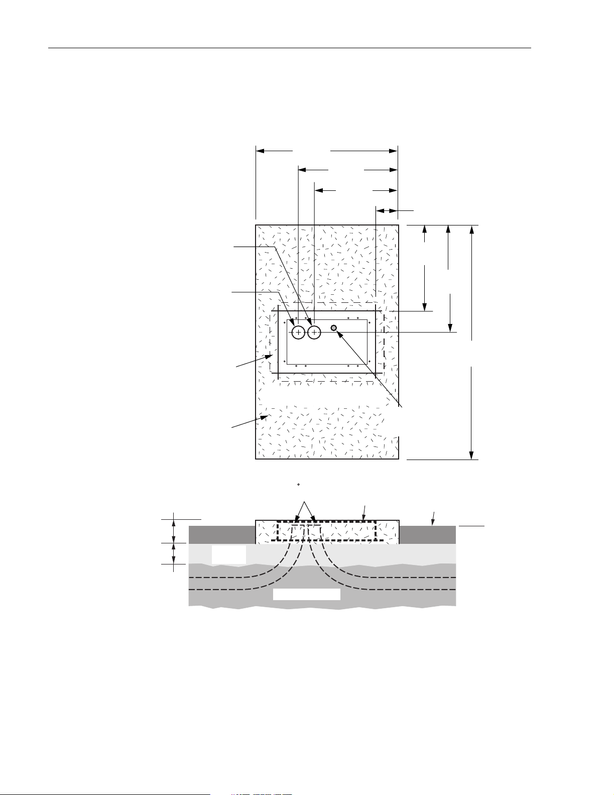
4.2 Cable Conduit Installation
Install the cable conduit from below as shown in Figure 8 and position it so that the top of each
upward bend will be located within the PMF opening at the indicated point. When installed, the
top of the conduit should be lo cate d 1 to 2 inches (2.54 to 5.08 cm) below the top of the finished
concrete pad. Install the conduit before pouring the pad.
25.8 IN.
(65.5 CM)
Figure 7. Pad Mount Frame Dimensions
16.4 IN.
(41.7 CM)
19065-C
4.3 Base Installation
Prepare a base f or the concrete pad that meets all local code requir ements. The base must have a
footing of 4 to 6 inches (10.2 to 15.2 cm) of sand or gravel (per local practice) on firmly
compacted soil. Refer to the construction diagram (see Figure 8) for details.
© 2004, ADC Telecommunications , Inc.
Page 15
Page 22
ADCP-96-015 • Issue 1 • July 2004
DISTRIBUTION CABLES
4 IN DUCT FOR
(LOCATE 1 - 2 INCHES
BELOW TOP OF PAD)
44.0 IN.
(111.8 CM)
30.6 IN.
(77.7 CM)
26.1 IN.
(66.4 CM)
9.0 IN.
(22.9 CM)
28.0 IN.
(71.1 CM)
4 IN DUCT FOR
FEEDER CABLES
(LOCATE 1 - 2 INCHES
BELOW TOP OF PAD)
PAD MOUNT FRAME
CAST IN PLACE
REINFORCED
CONCRETE PAD
6 IN.
(15.2 CM)
SAND OR
GRAVEL
4 IN. MIN.
(10.2 CM)
FRONT
DO NOT POUR CONCRETE INSIDE
THE PAD MOUNT FRAME
90 BEND
IN DUCT
COMPACTED SOIL
TOP OF PMF SHOULD
BE FLUSH WITH TOP
OF CONCRETE
33.0 IN.
(83.8 CM)
72.0 IN.
(182.9 CM)
GROUNDING ROD
(LOCATE 1 - 2 INCHES
BELOW TOP OF PAD)
TOPSOIL OR
DECORATIVE ROCK
GRADE
Page 16
© 2004, ADC Telecommunications , Inc.
19616-A
Figure 8. Constructing the Concrete Pad for the ACE-142S/142V Cabinet
Page 23

4.4 Concrete Pad Construction
Use the following procedure to construct the concrete pad:
1. Build a wood form for the concre te pad using 2 x 6 framing lumber as shown in Figure 9.
2. Locate the PM F as shown in the co nst ructio n diagra m (se e Figure 8). When installed, the
top surface of the PMF must be flush and level with the top of the concrete pad.
Note: Use temporary top framing to keep the top surface of the PMF flush and level with
the top of the concrete pad (see Figure 9).
3. Place reinfor cing material inside the form but outside of the PMF.
DIMENSIONS SHOW FINISHED
SIZE OF CONCRETE PAD
(182.9 CM)
ADCP-96-015 • Issue 1 • July 2004
44 IN.
(111.8 CM)
72 IN.
LEVELING
STAKES
(4 PLACES)
FRONT
PAD MOUNT
FRAME (PMF)
TEMPORARY
SUPPORT WIRES
(4 PLACES)
2 x 6 FRAMING
FOR FORM
19615-A
Figure 9. ACE-142S Cabinet Concrete Pad Framing
4. Verify that the PMF and form are level. Depending on the landscaping requirements, the
top surface of the concrete pad may be 0 to 3 inches (0 to 7.6 cm) above the final grade. The
weld nuts ar e c ov e red wi th pl ugs whic h mus t b e le ft in pla ce until t he e ncl osure is mo unte d.
5. Pour the c oncrete to form the pad but do not pour concret e into the center area of the PMF.
Note: Allow some concrete to flow under the flanges on the bottom of the PMF so the
PMF will be locked in place when the concrete hardens. However, do not allow concrete to
fill the center of the PMF. If necessary, partially fill the center of the PMF with sand or
gravel to pr event an inflow of concrete.
6. Remove the top framing and the temporary support wires when the concrete is ready to be
finished.
7. Allo w concrete to cure before proceeding with the installation.
© 2004, ADC Telecommunications , Inc.
Page 17
Page 24

ADCP-96-015 • Issue 1 • July 2004
4.5 Grounding System Installation
Install a grounding system (not provi ded ) that meets all loc al electr ical codes. C heck local codes
for grounding system installation, use of clamps, wire size, and any other grounding
requirements. Typically, #6 AWG copper wire is used for the ground wire. If the grounding
system includes a ground rod, install the rod (see Figure 8) within the PMF opening at the
indicated point. When installed, the top of the rod should be located 1 to 2 inches (2.54 to 5.08
cm) below the top of the finished concrete pad. Connect the grounding wire to the grounding
system. Leave sufficient slack in the grounding wire to allow it to be routed into the cabinet
after the cabinet is mounte d on the pad.
4.6 Mounting the Cabinet on the Concrete Pad
The following sections provide instructions for mounting the ACE-142S/142V cabinet on the
concrete pad. With the ACE-142S cabinet, the distribution cables must be installed after the
cabinet is mounted. With the ACE-142V cabinet, the distribution cables are pre-installed in the
cabinet by the factory. If mounting an ACE-142S cabinet, refer to Section 4.6.1 for the cabinet
mounting procedure. If mounting an ACE-142V cabinet with pre-installed distribution cables,
refer to Section 4.6.2 for t he cabinet mounting proce dur e. Use the 216B key tool to un-latch and
latch the cabinet doors as need ed during the mounting process.
Warning: Use appropriate lifting equipment when moving or installing the cabinet. Do not
stand under the cabinet as it is being hoisted into position for instal lation. A failure of the lifting
equipment could result in serious personal injury.
4.6.1 Mounting the ACE-142S Cabinet on a Concrete Pad
Use the following pr ocedures to mount the ACE-142S cabinet on the concrete pad.
1. Remove the plastic plugs that are in stalled in the threaded co rner holes of the PMF and
clean off an y concrete that may have adhered to the top of the PMF.
Note: Make sure all remnants of concrete are removed from the PMF prior to mounting
the cabinet. It is not necessary to use shims to level or align the cabinet as long as the top
surface of the PMF is clean and free of any installation debris.
2. If a ground spacer will not be installed, proceed to step 7. If a ground spacer (acces sory)
will be installed, align the ends of the left ground spacer section with the ends of the right
ground spacer section and then press the two sections together.
3. Place the assembled ground spacer in position for mounting on the PMF as shown in
Figure 10.
4. Align the mounting holes in the ground spacer with the mounting holes in the PMF.
5. Secure the ground spacer to the PMF using the four capscrews, four lock washers, and
four flat washers pro vided with the cabinet. Ti ghten all capscrews securely.
6. Open the rear door of the cabinet and remove the back section of the cabinet bottom cover
as described in Section 5.1. Then return to step 7 of this procedure to finish mounting the
cabinet.
Page 18
© 2004, ADC Telecommunications , Inc.
Page 25

ACE-142S
CABINET
(FRONT)
HEX BOLTS, FLAT
WASHERS, AND
NUTS (4 PLACES)
CAPSCREWS, LOCK
WASHERS, AND FLAT
WASHERS (4 PLACES)
ADCP-96-015 • Issue 1 • July 2004
GROUND
SPACER
(ACCESSORY)
CONCRETE
PAD
19617-B
CABLE
CONDUIT
PAD MOUNTING
FRAME (PMF)
Figure 10. Mounting the ACE-142S Cabinet on the Concrete Pad
7. Using appropriate lifting equipment, hold the cabinet in position for mounting over the
ground spacer or PMF.
8. Lower the cabinet onto the ground spacer or PMF and align the mounting holes in the
cabinet base with the threaded holes in the spacer or PMF.
9. If the installation includes a ground spacer, secure the cabinet to the spacer using the four
hex bolts, four flat washers and four nuts provided with the spacer. If the installation does
not include a gro und spacer, secure the cabi net to the PMF using the four hex bol ts, lock
flat washers, and four flat washers provided with the cabinet. Tighten all fasteners securely.
4.6.2 Mounting the ACE-142V Cabinet on a Concrete Pad
Use the following pr ocedures to mount the ACE-142V cabinet on the concrete pad.
1. Remove the plastic plugs that are in stalled in the threaded co rner holes of the PMF and
clean off an y concrete that may have adhered to the top of the PMF.
© 2004, ADC Telecommunications , Inc.
Page 19
Page 26

ADCP-96-015 • Issue 1 • July 2004
Note: Make sure all remnants of concrete are removed from the PMF prior to mounting
the cabinet. It is not necessary to use shims to level or align the cabinet as long as the top
surface of the PMF is clean and free of any installation debris.
2. If a ground spacer will not be installed, proceed to step 7. If a ground spacer (access ory)
will be installed, align the ends of the left ground spacer section with the ends of the right
ground spacer section and then press the two sections together.
3. Place the assembled ground spacer in position for mounting on the PMF as shown in
Figure 11.
ACE-142S
CABINET
(FRONT)
HEX BOLTS, FLAT
WASHERS, AND
NUTS (4 PLACES)
GROUND
CAPSCREWS, LOCK
WASHERS, AND FLAT
WASHERS (4 PLACES)
CONCRETE
PAD
PAD MOUNTING
FRAME (PMF)
CABLE
CONDUIT
SPACER
(ACCESSORY)
19816-A
Figure 11. Mounting the ACE-142V Cabinet on the Concrete Pad
4. Align the mounting holes in the ground spacer with the mounting holes in the PMF.
5. Secure the ground spacer to the PMF using the four capscrews, four lock washers, and
four flat washers pro vided with the cabinet. Ti ghten all capscrews securely.
Page 20
© 2004, ADC Telecommunications , Inc.
Page 27

ADCP-96-015 • Issue 1 • July 2004
6. Open the rear door of the cabinet and remove the back section of the cabinet bottom cover
as described in Section 5.1. Then return to step 7 of this procedure to finish mounting the
cabinet.
7. Using appropriate lifting equipment, hold the cabinet in position over the pad (see
Figure 11) so the cabinet is suspended over the rectangular opening in the top of the
ground spacer or PMF.
8. Feed each distribution cable into the appropriate conduit section and route to the splice
enclosure (not provided).
Note: The cables are coiled on spools for shipment. On each spool is a label that lis ts each
fiber subunit within the cabl e and the connect or panels wh ere each subunit is term inated.
After the cable is unspooled, label each cable with the corresponding fiber subunit and
connector panel designa tions. In additi on, tag or label the stub end of each cabl e so that the
cable can be identif ie d after being routed to the splice enclosure.
Note: A separate splice enclosure (not provided) is required for splicing the cabinet OSP
distribution cables to the system OSP distribution cables.
9. Lower the cabinet onto the ground spacer or PMF and align the mounting holes in the
cabinet base with the threaded holes in the spacer or PMF.
10. If the installation includes a ground spacer, secure the cabinet to the spacer using the four
hex bolts, four flat washers and four nuts provided with the spacer. If the installation does
not include a gro und spacer, secure the cabi net to the PMF using the four hex bol ts, lock
flat washers, and four flat washers provided with the cabinet. Tighten all fasteners securely.
© 2004, ADC Telecommunications , Inc.
Page 21
Page 28
ADCP-96-015 • Issue 1 • July 2004
5 FEEDER CABLE INSTALLATION AND SPLICING
This section describes how to install the OSP feeder cables in the ACE-142S/142V cabinet and
how to use the feeder cable spl i ce tray s .
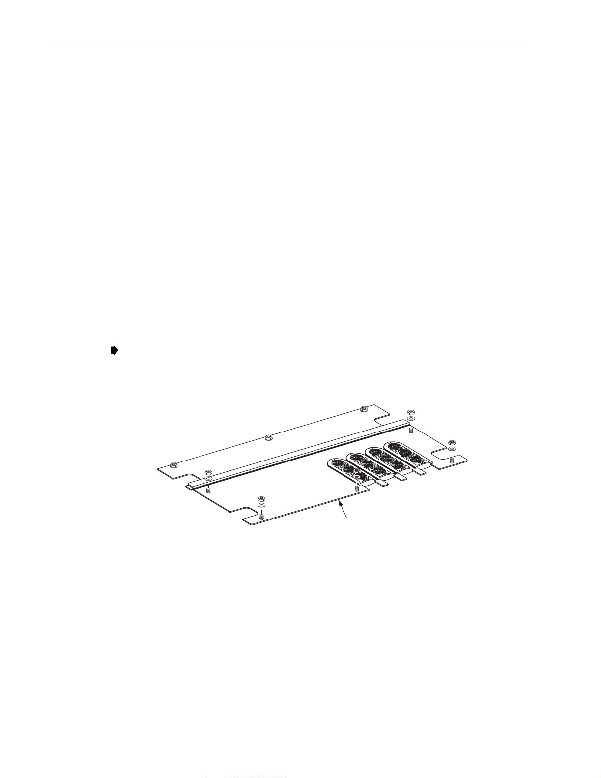
5.1 Bottom Cover Removal
The ACE-142S/142V cabinet is equipped with a two-piece bottom cover that prevents moisture
and dirt from entering the cabinet through the bottom. The cable-entry section of the bottom
cover m ust be removed to allow i nstallation of the OSP c ables. If the bottom cover was removed
previously, skip this section and proceed to Section 5.2. Use the following procedure to remove
the cable-entry section of the cabinet bottom cover from the cabinet:
1. Open the rear door of the cabine t.
2. Remove the five lock nuts and five flat washers that secure the cable-entry section of the
bottom cover to the cabinet as shown in Figure 12. Save the nuts and washers for reuse.
3. Lift up the cable-entry section of the bottom cover and push it toward the front of the
cabinet so it will be out of the way when the OSP cables are installed.
Note: Be careful not to da mage the gaskets tha t are attac hed to the underside of the bottom
cover. If the dis tribution ca bles are pr e-ins talled, the grom ments ma y be left in place over
the cables wh en the co ver i s removed.
Figure 12. Bottom Cover Cable-Entry Section Removal
5.2 Cabinet Grounding Wire Connection
Prior to mounting the cabinet, a grounding system should have been installed and a grounding
wire should have been connected to the grounding system (see Section 3.5 or Section 4.5). Use
the follo wing procedure to attached the grounding wire to the cabinet grounding lug:
19608-A
REMOVE BACK SECTION
OF BOTTOM COVER
1. Locate the grounding wire that w as installed prior to mounting the cabinet and pull several
feet of slack up and into the cab in et .
Page 22
© 2004, ADC Telecommunications , Inc.
Page 29

ADCP-96-015 • Issue 1 • July 2004
2. Attach the grounding wire to the grounding lug as shown in Figure 13. The grounding lug
can be used for #6 – #14 AWG wire. Tighten the grounding lug set screw securely.
3. Lea ve suffic ient slack so the grounding wire can be repositioned as needed when the cable
entry section of the bottom co ver is re-installed.
NOTE: SHOWN WITH BOTH
THE FRONT AND REAR
SECTIONS OF THE BOTTOM
COVER (MOISTURE BARRIER)
REMOVED.
5.3 Feeder Cable Installation
The OSP feeder cable enters/exits the ACE-142S/142V cabinet from the bottom. At the entry/
exit point to the cabinet, the feeder cable is secured with a clamp. Beyond the clamp, the outer
sheath of the cable is removed to expose the optical fibers. The feeder cable is typically a 12- to
24-fiber cable with stranded or ribbon type fiber construction. Moisture blocking and/or
grounding kits should be installed (as required by local practice) to protect the exposed optical
fibers. From t he clamp ing point , the opti cal fibers are routed to sp lice tra ys for splic ing to th e
splitter input fibers.
CABINET GROUNDING LUG
(#6 - #14 AWG WIRE)
Figure 13. Grounding Wire Connection To Cabinet
GROUNDING
STUDS FOR
OSP CABLES
WITH METALIC
ELEMENTS
19610-A
Note: If additional splitter modules will be installed in the cabinet as part of the initial
installation, complete splitter installation before proceeding with feeder cable installation.
Refer to Section 10 for the splitter module installation procedure.
Use the following procedure to install the feeder cable:
1. Route the OSP feeder cable into the cabinet from the bottom. If the cabinet is mounted on
a concrete pad, use the duct on the right side.
2. Pull the cable up through the cabinet and strip off 156 inches (396 cm) of the outside cable
sheath to expose the f iber subunits.
3. Install moisture-blocking and/or grounding kits as required by local practice. Follow the
installati on instructions provided with each kit.
© 2004, ADC Telecommunications , Inc.
Page 23
Page 30

ADCP-96-015 • Issue 1 • July 2004
Note: A blocking kit is recommended when installing ribbon cable. The blocking kit
includes plastic tubes that protect the fiber ribbons and prevent damage. If a grounding kit
is required, strip the cable sheath to the recommended length and install the grounding
clamp prior to se curi ng the cab le to the cab inet .
4. Three cable clamping positions are provided for securing feeder cables as shown in
Figure 14. Select one of the clamping positions as the attachment point for the cable.
Note: Use the middle cable clamp position first and the top clamp position second when
installing the feeder cables. The bottom clamp position is an extra. The bracket for the top
row of clamps may be removed if necessary to facilitate cable installation.
19740-A
CLAMPS FOR
ATTACHING THE
FEEDER CABLES
(3 PLACES)
Figure 14. Feeder Cable Clamping Positions
5. Back out the two 2-inch long 6-32 screws that secure the two clamps and cover plate to the
cabinet.
6. Assemble the clamps (and grommet if required) on the cable as shown in Figure 15 an d
then secure the cable to cabinet at the clamping position selected in step 4.
7. If a grounding kit was installed on the cable, attach the cable grounding lead to one of the
grounding studs locate d within the cabinet (see Figure 13).
8. From the cable clamping location, route the first fiber subunit up the right side of the
cabinet as shown in Figure 16.
Page 24
© 2004, ADC Telecommunications , Inc.
Page 31

CABLE
USE GROMMET
FOR SMALLER
DIAMETER CABLES
COVER
PLATE
ADCP-96-015 • Issue 1 • July 2004
FEEDER CABLE
SPLICE TRAYS
CLAMPS
Figure 15. Cable Clamp Assembly for Feeder Cable
SECURE FEEDER CABLE
AND SPLITTER INPUT FIBERS
TOGETHER AT THIS POINT
19623-A
SCREWS
SPLITTER INPUT
FIBER ROUTING
CENTER PANEL
TIE POINT
SECURE FEEDER CABLE
TO PANEL ON RIGHT
SIDE OF CABINET
19625-A
Figure 16. Feeder Cable Fibers Routed To Splice Trays
© 2004, ADC Telecommunications , Inc.
CABLE
CLAMP
Page 25
Page 32

ADCP-96-015 • Issue 1 • July 2004
9. Secure the fiber subunit to the panel on the right side of the cabinet using the tie points
provided.
10. From the right side of the cabinet, route the fiber subunit to the center panel located just
below the spli tter modules and secure using the tie point provided.
11. From the center panel, route the fiber subunit to the splice wheel used for the splitter
module input fibe rs following the same path as the splitter module input fibers.
12. Repeat steps 1–11 fo r each fee der cable subunit and each additional feede r cable.
5.4 Feeder Cable and Splitter Input Fiber Splicing
The OSP feeder cable fibers must be spliced to the splitter input fibers. Up to twelve splitter
modules may be mounted in the cabinet so that a maximum of twelve feeder splices may be
required. Round splice trays are used for splicing and seven splice tray mounting slots are
provided. Each splice tray can hold up to 12 splices. Use the following procedure to install the
feeder cable fibers and splitter input fibe rs in each splice tray in preparation for splicing:
1. The input fibers from each splitter are routed to a splice tray located on the top left side of
the cabinet. Locate the splice tray that was used for the splitter input fibers and remove
that tray from the cabinet.
2. Uncoil the spli tter input fibers from the splice tray.
Note: The splitter input fibers are temporarily coiled around the splice tray for storage.
3. Secure the splitter input fibers and the feeder cable fiber subunit together at the point
where the two com e toget her before enteri ng the splice tray (s ee Figure 16). Adjust slack
as necessary to prevent binding.
4. Check the routing of the splitter input fibers and adjust as needed to relieve tension or
remove excess slack.
5. Starting at the common tie point within the cabinet, measure and mark the f iber cut lengths
for the splitter input fibers and the feeder cable fiber subunits as shown in Figure 17.
CUT LENGTH* 68 TO 146 IN
(173 TO 371 CM)
BREAKOUT
LENGTH 37 IN
(94 CM)
BREAKOUT
LENGTH 48 IN
(122 CM)
SPLITTER INPUT FIBER
FEEDER CABLE
FIBER SUBUNIT
*THE CUT LENGTH MUST BE
THE SAME FOR BOTH FIBERS
COMMON TIE
POINT IN CABINET
19220-A
Figure 17. Cut Length and Breakout Length for Feeder Cable and Splitter Input Fiber
Page 26
© 2004, ADC Telecommunications , Inc.
Page 33

ADCP-96-015 • Issue 1 • July 2004
6. Cut both the splitter input fibers and the feeder cable fiber subunit at the cut length mark.
Make sure that the splitter input fibers and the feeder cable fiber subunit are of equal
length and the overall length is within the range specified.
7. Starting at th e cut end, measure b ackward and ma rk the break-out len gths for the feede r
cable fibers and the splitter input fibers.
8. Starting at the breakout mark, remove the protective jackets to expose the feeder cable
fibers (may be stranded or ribbon fibers) and the splitter input fibers.
9. Instal l the splitter input fibers and the feeder cable fibers in the splice tray and complete all
splices per local practice. Refer to Section 7 for information on how to use the round
splice trays and then retu rn to Step 10 to continue this procedure.
10. After splici ng is comp leted, the splice tray cover replac ed, and the excess slack roll ed up,
insert the splice tray into the designated mounting slot.
11. Repeat this procedure for each feeder cable fiber sub unit.
12. Designation labels, shown in Figure 18 and Figure 19, are provided on the front door of
the cabinet for recording splitter module information. For each splitter, indicate the splice
tray number, feeder cable fiber number, splitter module number, and service information.
FRONT DOOR REAR DOOR
SPLITTER
MODULES
12
11
10
9
8
7
6
5
SPLITTER MODULE LABEL
4
3
2
1
19629-A
Figure 18. Splitter Module Designation Label - Type 1
© 2004, ADC Telecommunications , Inc.
Page 27
Page 34

ADCP-96-015 • Issue 1 • July 2004
FRONT DOOR REAR DOOR
6
5
4
3
2
1
SPLITTER
MODULES
12
11
10
9
8
7
SPLITTER MODULE LABEL
Figure 19. Splitter Module Designation Label - Type 2
19739-A
Page 28
© 2004, ADC Telecommunications , Inc.
Page 35

6 DISTRIBUTION CABLE INSTALLATION AND SPLICING
This section desc ribes how to ins ta ll the OSP distribu tion cables in the ACE-142S/142V cabinet
and how to use the distribution cable splice trays. If the cabinet is equipped with pre-installed
distribution cables, refer to Section 6.2 for the bottom cover installation proc edure.
6.1 Distribution Cable Installation
The OSP distribution cables enter the ACE-142S/142V cabinet from the bottom. At the entry/
exit point to the cabinet, each distribution cable is secured with a clamp. Beyond the clamp, the
outer sheath of the cable is removed to expose the optical fibers. Moisture blocking, grounding,
and fanout kits must be installed (as required by local practice) to protect the exposed optical
fibers. The OSP distribution cable fiber count may be any multiple of 72 (depending on the
number of conne ctor panels) with stranded or ribbon type fiber construction. From the clamping
point, the optical fibers are routed to the splice tr ays for splicing to t he connector panel pigtails.
Use the following pr ocedure to install the distribution cable:
1. Route the OSP distribution cable into the cabinet from the bottom. If the cabinet is
mounted on a concrete pad, use the duct on the left side.
ADCP-96-015 • Issue 1 • July 2004
2. Pull the cable up through the cabinet and strip off 156 inches (396 cm) of the outside cable
sheath to expose the f iber subunits.
3. Install moisture-blocking, fanout, and grounding kits as required by local practice. Follow
the installation instructions provided with each kit.
Caution: A fanout kit is required when installing ribbon cable. The fanout kit includes plastic
tubes that protect the fiber ribbons and prevent damage.
4. Nine cable clamping positions are provided near the center of the cabinet as shown in
Figure 20. Select one of the clamping positions as the attachment point for the cable.
Note: Use the middle cable clamp positions first and the top clamp positions second when
installing the distribution cables. The bottom clamp positions are extra. The bracket for the
top row of clamps may be removed if necessary to facilitate cable installation.
19741-A
CLAMPS FOR
ATTACHING THE
DISTRIBUTION CABLES
(9 PLACES)
Figure 20. Distribution Cable Clamping Positions
© 2004, ADC Telecommunications , Inc.
Page 29
Page 36

ADCP-96-015 • Issue 1 • July 2004
5. Back out the two 2-inch long 6-32 screws that secure the two clamps and cover plate to the
cabinet.
6. Assemble the clamps (and grommet if required) on the cable as shown in Figure 21 an d
then secure the cable to cabinet at the clamping position selected in step 4.
CABLE
USE GROMMET
FOR SMALLER
DIAMETER CABLES
COVER
PLATE
CLAMPS
19623-A
SCREWS
Figure 21. Cable Clamp Assembly for Distribution Cable
7. If a grounding kit was installed on the cable, attach the cable grounding lead to one of the
grounding studs locate d within the cabinet (see Figure 13).
8. Repeat steps 1 through 7 for each additional distribution cable.
9. From the cable clamping location, route the fi rst six distrib ut ion cable f i ber subunit s up the
right side of the cabin et as shown in Figure 22.
10. Secure the subunits to the panel on the right side of the cabinet using the tie points
provided.
11. Use a Phillips screwdriver to remove the four screws that secure the handle assembly to
the back of connector panel #1 (top panel) as shown in Figure 23. Save each screw for
reuse.
12. Remove the handle assembly from the back of connector panel #1.
13. Route the first six fiber subunits across the back of connector panel #1 to splice trays 1–6
located on the left side of the cabinet.
Note: The splice trays are numbered 1 through 30 starting with the top splice tray in
connector panel #1. Route all distribution cable fibers to the splice trays starting with the
top tray and working towards the bottom tray.
14. Secure each fiber subunit to the back of the connector panel using the tie points indicated
in Figure 22.
15. Use the same basic procedure specified in steps 8 through 14 for routing the remaining
distribution cable fiber subunits to the remaining distribution cable splice trays. Repea t the
routing process until every fiber subunit is routed to a splice tray.
Page 30
© 2004, ADC Telecommunications , Inc.
Page 37

DISTRIBUTION CABLE
SPLICE TRAYS 1 - 6
DISTRIBUTION CABLE
SPLICE TRAYS 7 - 12
ADCP-96-015 • Issue 1 • July 2004
DISTRIBUTION CABLE
TIE OFF COLUMNS
(CONNECTOR PANEL #1)
DISTRIBUTION CABLE
SPLICE TRAYS 13 - 18
DISTRIBUTION CABLE
SPLICE TRAYS 19 - 24
DISTRIBUTION CABLE
SPLICE TRAYS 25 - 30
SECURE DISTRIBUTION
CABLE TO PANEL ON
RIGHT SIDE OF CABINET
CABLE
CLAMPS
19633-A
Figure 22. Distribution Cable Fibers Routed to Splice Trays
REAR HANDLE
ASSEMBLY
Figure 23. Rear Handle Assembly Removal and Installation
© 2004, ADC Telecommunications , Inc.
19614-A
Page 31
Page 38

ADCP-96-015 • Issue 1 • July 2004
6.2 Bottom Cover Installation
The cable-entry section of the bottom cover must be replaced following installation of the
grounding wire, feeder cable(s), and distribution cable(s). Use the following procedure to
replace the cable-entry section of the bottom cover:
1. Locate the b otto m cover (ca ble-entry secti on) that was rem oved fr o m th e cabi n et i n step 2
of Section 5.1.
2. Determine which grommets will be use d for sealing the cable entry/exit points and remove
those grommets from their mounting slots in the bottom cover.
3. Using a utility knife, cut through the slit that runs lengthwise down the center of each
grommet as shown in Figure 24.
4. Remove enough cable cutout sections from each grommet to accommodate the size and
number of cables that will pass thr ough the grommet.
REMOVE CABLE
CUTOUT SECTIONS
BOTTOM
COVER
CUT SLIT
GROUNDING
WIRE
DETAIL DRAWIING
OF GROMMET
Figure 24. Bottom Cover Installation
GROMMET
FEEDER
CABLE
DISTRIBUTION
CABLES
19609-A
5. Install the grommets on the cables.
Note: More than one cable may have to pass though the same grommet.
6. Insert the grommets into their respective mounting slots in the bottom cover.
Page 32
© 2004, ADC Telecommunications , Inc.
Page 39

7. Slide the bottom cover down to the bottom of the cabinet.
8. Align the five holes in the bottom cover with the f ive studs around the edge of the cabinet.
9. Install a flat washer and lock nut (removed in step 1 of Section 5.1) on each stud and
tighten securely.
6.3 Distribution Cable and Connector Panel Pigtail Splicing
The distribution cable must be spliced to the connector panel pigtails. Up to five 72-port
connector panels may be mounted in the cabinet which requires a maximum of 360 distribution
splices. Round splice trays are used for splicing and six splice tray mounting slots are provided
per panel. This equates to a maximum of 30 spice tra ys when fi v e connec tor panels are inst al led.
Each splice t ray can hold up to 12 splices. Use the fol lowing procedure to install the distr ibution
cable fibers and the connector panel pigtails in the splice tray in preparation for splicing:
1. Locate splice tr ay #1 (on the lef t side) and remove that tray from the cabinet.
Note: The pigtails from each connector panel are grouped into six 12-fiber subunits. Each
pigtail subunit is routed to a spli ce tray locat ed on the left s ide of the cabin et. The splic e
trays are numbered consecutively 1 through 30 starting with at the top. The subunit, port,
fiber, and splice tray designations for each connector panel are shown in Table 5.
ADCP-96-015 • Issue 1 • July 2004
2. Uncoil the connector panel pigtail subunit from the splic e tray.
Note: Each connector panel pigtail subunit is temporarily coiled around a splice tray for
storage.
3. Starting at the last column (left side) of tie points on the rear side of the connector panel,
measure and mark the fiber cut lengths for the distribution cable fiber subunits and the
connector panel fiber subunits as sho wn in Figure 25.
CUT LENGTH* 68 TO 146 IN
(173 TO 371 CM)
BREAKOUT
LENGTH 37 IN
(94 CM)
BREAKOUT
LENGTH 48 IN
(122 CM)
*THE CUT LENGTH MUST BE
THE SAME FOR BOTH FIBERS
Figure 25. Cut Length and Breakout Length for Distribution Cable and Connector Panel Fibers
DISTRIBUTION CABLE
FIBER SUBUNIT
CONNECTOR PANEL
FIBER SUBUNIT
COMMON
TIE POINT IN CABINET
19276-A
4. Cut both the distribution cable fiber subunit and the connector panel pigtail subunit at the
cut length mark. Make sure that the distribution cable fiber subunit and the connector
panel pigtail subunit are of equal length and the overall length is within the range
specified.
© 2004, ADC Telecommunications , Inc.
Page 33
Page 40

ADCP-96-015 • Issue 1 • July 2004
Table 5. Connector Panel Sub Unit, Port, Fiber, and Splice Tray Designations
SUB
UNIT
1
2
3
SUB
PORT FIBER SPLICE TRAY
1 1 (Blue) Tray 1 if Panel 1
UNIT
PORT FIBER SPLICE TRAY
37 1 (Blue) Tray 4 if Panel 1
2 2 (Orange) 38 2 (Orange)
3 3 (Green) 39 3 (Green)
4 4 (Brown) 40 4 (Brown)
Tray 7 if Panel 2
Tray 13 if P ane l 3
5 5 (S late) 41 5 (Sla te)
6 6 (White) 42 6 (White)
7 7 (Red) 43 7 (Red)
Tray 19 if P ane l 4
Tray 25 if P ane l 5
4
8 8 (Black) 44 8 (Black)
9 9 (Yellow) 45 9 (Yellow)
10 10 (Violet) 46 10 (Violet)
11 11 (Rose) 47 11 (Rose)
12 12 (Aqua) 48 12 (Aqua)
13 1 (Blue) Tray 2 if Panel 1
49 1 (Blue) Tray 5 if Panel 1
14 2 (Orange) 50 2 (Orange)
15 3 (Green) 51 3 (Green)
16 4 (Brown) 52 4 (Brown)
Tray 8 if Panel 2
Tray 14 if P ane l 3
17 5 (Sla te) 53 5 (Slate)
18 6 (White) 54 6 (White)
19 7 (Red) 55 7 (Red)
Tray 20 if P ane l 4
Tray 26 if P ane l 5
5
20 8 (Black) 56 8 (Black)
21 9 (Yellow) 57 9 (Yellow)
22 10 (Violet) 58 10 (Violet)
23 11 (Rose) 59 11 (Rose)
24 12 (Aqua) 60 12 (Aqua)
25 1 (Blue) Tray 3 if Panel 1
61 1 (Blue) Tray 6 if Panel 1
26 2 (Orange) 62 2 (Orange)
27 3 (Green) 63 3 (Green)
28 4 (Brown) 64 4 (Brown)
Tray 9 if Panel 2
Tray 15 if P ane l 3
29 5 (Sla te) 65 5 (Slate)
30 6 (White) 66 6 (White)
31 7 (Red) 67 7 (Red)
Tray 21 if P ane l 4
Tray 27 if P ane l 5
6
32 8 (Black) 68 8 (Black)
33 9 (Yellow) 69 9 (Yellow)
34 10 (Violet) 70 10 (Violet)
35 11 (Rose) 71 11 (Rose)
36 12 (Aqua) 72 12 (Aqua)
Tray 10 if Panel 2
Tray 16 if Panel 3
Tray 22 if Panel 4
Tray 28 if Panel 5
Tray 11 if Panel 2
Tray 17 if Panel 3
Tray 23 if Panel 4
Tray 29 if Panel 5
Tray 12 if Panel 2
Tray 18 if Panel 3
Tray 24 if Panel 4
Tray 30 if Panel 5
Page 34
© 2004, ADC Telecommunications , Inc.
Page 41

ADCP-96-015 • Issue 1 • July 2004
5. Starting at the cut end, measure backward and mark the break-out lengths for the
distribution cable fibers and the connecto r panel fibers.
6. Starting at the breakout mark, remove the protective jackets to expose the distribution
cable fibers (may be stranded or ribbon fibers) and the connector panel pigtail fibers.
7. Install the connector panel pigtail subunit and the distribution cable fiber subunit in the
splice tray and complete all splices per local practice. Refer to Section 7 for details and
then return to Step 8 to continue this proce dure.
8. After splicin g is compl eted, the splice tray cover replac ed, and the excess slac k rolled up,
insert the splice tray into the designated mounting slot.
9. Repeat this procedure for each connector panel pigtail sub unit.
10. When all splices have been completed, re-install the rear handle assembly on the back of
each connector panel (see Figure 23).
11. Connector panel designation labels, shown in Figure 26 and Figure 27, are provided on the
front door of the cabinet for recording subscriber information. For each connector panel,
indicate the subscriber address and service information and the fiber and cable number if
not specified. Splice tray designation labels, shown in Figure 28, are provided on the rear
door of the cabinet for recording distribution cable information. For each splice tray,
indicate the distribution cable and subunit numb er.
FRONT DOOR REAR DOOR
1234
1-LEFT
2-LEFT
3-LEFT
4-LEFT
5-LEFT
1-RIGHT
2-RIGHT
3-RIGHT
4-RIGHT
5-RIGHT
SPL TRAY 1
FBR 1
19 20 21 22
SPL TRAY 2
PANEL
FBR 7
1
37 38 39 40
SPL TRAY 4
FBR 1
55 56 57 58
SPL TRAY 5
FBR 7
SPL TRAY 1
FBR 2
SPL TRAY 2
FBR 8
SPL TRAY 4
FBR 2
SPL TRAY 5
FBR 8
SPL TRAY 1
FBR 3
SPL TRAY 2
FBR 9
SPL TRAY 4
FBR 3
SPL TRAY 5
FBR 9
SPL TRAY 1
FBR 4
SPL TRAY 2
FBR 10
SPL TRAY 4
FBR 4
SPL TRAY 5
FBR 10
LABEL FOR LEFT SIDE
OF CONNECTOR PANEL #1
19634-A
Figure 26. Connector Panel Designation Label - Type 1
© 2004, ADC Telecommunications , Inc.
Page 35
Page 42

ADCP-96-015 • Issue 1 • July 2004
FRONT DOOR REAR DOOR
6
5
4
3
2
1
1
2
3
4
5
FBR FBR FBR FBR FBR FBR
CABLE CABLE CABLE CABLE CABLE CABL
19
FBR FBR FBR FBR FBR FBR
CABLE CABLE CABLE CABLE CABLE CABLE
PANEL
37
1
FIBERS
1-72
FBR FBR FBR FBR FBR FBR
CABLE CABLE CABLE CABLE CABLE CABLE
55
FBR FBR FBR FBR FBR FBR
CABLE CABLE CABLE CABLE CABLE CABLE
21
20
39
38
57
56
LABEL FOR
CONNECTOR PANEL #1
22
40
58
Figure 27. Connector Panel Designation Label - Type 2
LABEL FOR DISTRIBUTION
CABLE SPLICE TRAYS
SPLICE TRAY 1
PANEL 1
FRONT DOOR
FIBERS 1-12
SPLICE TRAY 2
PANEL 1
FIBERS 13-24
SPLICE TRAY 3
PANEL 1
FIBERS 25-36
SPLICE TRAY 4
PANEL 1
FIBERS 37-48
SPLICE TRAY 5
PANEL 1
23
41
59
24
42
60
19738-A
REAR DOOR
Page 36
© 2004, ADC Telecommunications , Inc.
19635-A
Figure 28. Splice Tray Designation Labels
Page 43
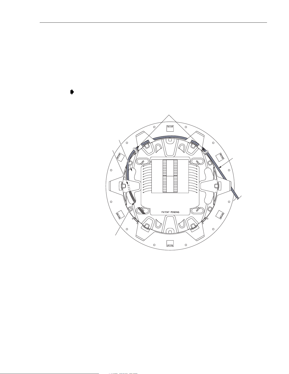
7 GUIDELINES FOR USING ROUND SPLICE TRAYS
This section provides guidelines for using the round splice trays that are provided with the
ACE-142S/142V cabinet. Use the following procedure for installing the fibers in the tray:
1. Remove the top and bottom covers from the splice tray.
2. Secure subunit A to the splice tray at the points shown in Figure 29.
Note: If installing the feeder cable, subunit A is the feeder cable subunit. If installing the
distribution cable, subunit A is the connector panel pigtail subunit.
TRANSITION POINT
FROM TOP TO BOTTOM
FIBER
BREAKOUT
POINT
SUBUNIT A
TIE POINTS
ADCP-96-015 • Issue 1 • July 2004
NOTE 1: FOLLOW SUBUNIT A
ROUTING FOR FEEDER CABLE
OR CONNECTOR PANEL FIBERS
SUBUNIT A
(SEE NOTE 1)
TOP SIDE
STRANDED/RIBBON FIBER
(ROUTE TO BOTTOM SIDE)
19280-A
Figure 29. Subunit A Tie Points
3. Insert the breakout fibers through the opening where the fibers transition from the top to
the bottom of the splice tray (see Figure 29).
4. Adjust subunit A so the fiber breakout is positioned at the transition opening.
5. Turn the tray over and continue routing the breakout fibers around the spools as shown in
Figure 30 and then back to the top sid e of the splice tray.
© 2004, ADC Telecommunications , Inc.
Page 37
Page 44

ADCP-96-015 • Issue 1 • July 2004
TRANSITION POINT
FIBER
BREAKOUT
POINT
ROUTE TO
TOP SIDE
STRANDED/RIBBON
FIBERS
BOTTOM SIDE
AFTER ROUTING CABLES,
REPLACE BOTTOM COVER
19229-A
Figure 30. Routing Subunit A Around Back Side of Splice Tray
6. Replace the splice tray bottom cover and then turn the tray over to the top side.
7. Route the break out fi bers at least 1.5 times around the insi de of the tray making the loop as
large as possible to ensure maximum fiber storage as shown in Figure 31.
Page 38
© 2004, ADC Telecommunications , Inc.
Page 45

ADCP-96-015 • Issue 1 • July 2004
MAKE LOOP AS LARGE AS
POSSIBLE TO ENSURE
MAXIMUM FIBER STORAGE
ROUTE FIBERS 1.5 TIMES
AROUND INSIDE OF TRAY
TOP SIDE
Figure 31. Routing Subunit A Around Front Side of Splice Tray
19230-A
8. Secure subunit B to the splice tray at the points shown in Figure 32. If multiple fibers are
being installed, route all fibers simultaneously.
Note: If installing the feeder cable, subunit B is the splitter input fiber(s). If installing the
distribution cable, subunit B is the distribution cable subuni t.
9. Adjust sub unit B so the fiber breakout is positioned at the point shown (see Figure 32).
10. Route the breakout fibers at least two times around the inside of the tray making the loop
as large as possible to ensure maximum fiber storage.
11. Splice the subunit A fibers to the subunit B fibers as specified by local policies and
procedures.
12. Replace t he splice tra y top cover and then t urn the splic e tray in a clock wise direct ion to
roll up the excess slack.
13. Return to step 10 in Section 5.4 or step 8 in Section 6.3 to complete the corresponding
OSP cable installation pr ocedure.
© 2004, ADC Telecommunications , Inc.
Page 39
Page 46

ADCP-96-015 • Issue 1 • July 2004
SUBUNIT A
TIE POINTS
SUBUNIT B
TIE POINTS
ROUTE FIBER 2 TIMES
AROUND INSIDE OF TRAY
NOTE 1: FOLLOW SUBUNIT B
ROUTING FOR DISTRIBUTION CABLE
OR SPLITTER INPUT FIBERS
FIBER BREAKOUT
SUBUNIT A
POINT
SUBUNIT B
(SEE NOTE 1)
TOP SIDE
MAKE LOOP AS
19281-A
LARGE AS POSSIBLE TO
ENSURE MAXIMUM
FIBER STORAGE
Figure 32. Routing Subunit B Around Front Side of Splice Tray
Page 40
© 2004, ADC Telecommunications , Inc.
Page 47

8 PRE-INSTALLED DISTRIBUTION CABLE CONFIGURATION
ACE-142V cabinets are equipped with pre-installed distribution cables that enter/exit the
cabinet from the bottom. At the entry/exit points, each cable is secured with a clamp. Beyond
the clamp, the outer sheath of each cable is remo ved and the fibers are broken out int o subunits.
Each subunit is fanned out into twelve individual fibers and each fiber is terminated with a
connector . The fi ber sub units are routed to the connector panels where each f iber is conne cted to
a bulkhead adapter.
Each connector panel can accommodate six 12-fiber subunits which equals 72 fiber ports per
panel. Each distribution cable typically has a fiber count that is a multiple of 72 to correspond
with the number of ports provided by each connector panel. Depending on the option ordered,
cabinets may be equipped with up to nine distribution cables. A drawing is provided with each
ACE-142 V cabinet that indicates the c onnector panel and optical p ort assignments for the fibers
within each distrib ution cable. Refer to this drawing whe n splicing to determine the terminating
port for each fiber within each cable. A diagram of a typical distribution cable configuration is
shown in Figure 33.
ADCP-96-015 • Issue 1 • July 2004
BACK
SPLITTERS SPLITTERS
PANEL 1
FIBERS
1 -72
PANEL 2
FIBERS
73 - 144
PANEL 3
FIBERS
1 - 72
PANEL 4
FIBERS
73 - 144
PANEL 5
FIBERS
145 - 216
CABLE 2
SUBUNITS
1 - 18
(216 FIBERS)
CABLE 1
SUBUNITS
1 - 12
(144 FIBERS)
19817-A
Figure 33. Pre-Installed Distribution Cable - Typical Configuration
© 2004, ADC Telecommunications , Inc.
Page 41
Page 48
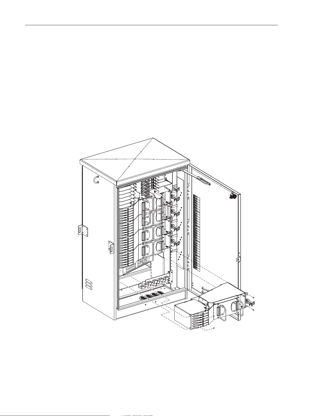
ADCP-96-015 • Issue 1 • July 2004
9 CONNECTOR PANEL INSTALLATION
The ACE-142S/142V cabinet can accommodate up to five 72-port connector panels which will
provide a total of 360 distribution ports. If the cabinet is not pre-loaded with five connector
panels, then additional connector panels and round splice trays may be installed as needed. Use
the follo wing procedure to install additional connector panels in the cabinet:
1. Position the connector panel in the next available mounting space within the cabinet as
shown in Figure 34.
2. Secure the connector panel to the cabinet using the four machine screws provided.
Page 42
© 2004, ADC Telecommunications , Inc.
19737-A
Figure 34. Connector Panel Installation
Page 49

10 SPLITTER MODULE INSTALLATION
The ACE-142S/ 142V cabinet can accommodate up to twelve 1x8 or 1x32 splitter modules. The
cabinet can support a maximum of 360 output ports for distribution. Use the following
procedure to install additional splitters in the cabinet:
1. Instal l the splitter module in the next available mounting position as shown in Figure 35.
Note: Install splitters in the order shown in Figure 35, beginning on the right side of the
splitter compart ment.
2. Route the splitter output fibers to the connector storage panel or to the designated
customer port. Re fer t o Section 11 for the routing procedure.
3. Route the splitter input fiber to the designated splice tray at the back of the cabinet as
shown in Figure 36. Up to 12 fibers ma y be spliced wi thi n each spl ice t ray.
ADCP-96-015 • Issue 1 • July 2004
12
11
10
9
8
7
6
5
4
3
2
1
DETAIL DRAWING OF
SPLITTER MODULES
Figure 35. Splitter Module Installation
19636-A
Page 43
© 2004, ADC Telecommunications , Inc.
Page 50

ADCP-96-015 • Issue 1 • July 2004
FEEDER CABLE
SPLICE TRAYS
SPLITTER INPUT
FIBER ROUTING
19637-A
Figure 36. Routing Splitter Input Fibers
4. Remove the splice tray and then coil up the splitter input fiber around the outside edge of
the tray for temporary storage.
5. Refer to Section 5.4 for the feeder cable and spl itter input fiber splicing procedures.
Page 44
© 2004, ADC Telecommunications , Inc.
Page 51

11 ROUTING AND CONNECTING THE SPLITTER OUTPUT FIBERS
The splitter modules are mounted at the top of the ACE-142S/142V cabinet. When a splitter
module is installed, the output fibers are routed to the storage panel located at the bottom of the
cabinet. The o u tput fibers are t em p or aril y “pa rke d” in t he storag e pane l un t il they are n eeded to
provide service. Service to a subscriber is enabled by removing an unused output fiber from the
storage panel and routing it to the appropriate connector panel for connection to the subscriber
port.
11.1 Storing The Splitter Output Fibers
Use the following pr ocedure to store the splitter output fibers.
1. Following installation of a splitter, route each splitter output fiber over the top spool on the
right side of the cabinet as shown in Figure 37.
2. Locate an unused stor age port on the storage panel.
3. Hold the output fiber connector near the storage port adapter.
4. Use the slack storage spools on the right side of the cabinet to store any excess fiber s lack.
ADCP-96-015 • Issue 1 • July 2004
5. Insert the output fiber connector into the storage panel port adapter.
Figure 37. Routing To Storage Panel
19638-A
Page 45
© 2004, ADC Telecommunications , Inc.
Page 52

ADCP-96-015 • Issue 1 • July 2004
11.2 Enabling Service To a Subscriber
Use the following procedure to enable se rv ice to a sub scri b er :
1. Check the designation labels on the cabinet door to determine the connector panel and port
number that corresponds to the address of the subscriber.
2. Locate the subscriber port on the specified connector panel and remove both the adapter
dust cap and the connector ferrule dust cap.
3. Select and remove an unused splitter output fiber from the storage panel and carefully
work it free of any other fibers .
4. Remove the ferrule dust cap from the connector and then clean the connector as specified
in the Optical Fiber Systems Cleaning and Mating Instructions (ADCP-90-159)
5. Hold the output fiber connector near the subscriber port.
6. Use the slack storage spools on the right side of the cabinet to store any excess fiber slack
as shown in Figure 38.
7. Insert the output fiber connector into the connector pa nel port adapter .
Page 46
© 2004, ADC Telecommunications , Inc.
19639-A
Figure 38. Routing To Connector Panels
Page 53

12 MAINTENANCE AND REPAIR PROCEDURES
The ACE-142S/142V cabinet requires no regular maintenance to insure continuous and
satisfactory operation. Maintenance is limited to repairing or replacing any cabinet components
that may be damaged or broken in the course of normal operation. The following sections
provide procedur es for repairing or replacing common cabinet components.
12.1 Painting
Brush-in-cap type bottles of paint are available (see Table 2) for touching-up nicks and
scratches in the factory coat of paint. Lightly sand the area to be painted and then clean it
thoroughly to remove any dirt, dust, or foreign matter. Shake the paint bottle until thoroughly
mixed and then apply a light coat of paint to the damaged area using the small brush attached to
the cap. Wait until the paint is dry and then apply a second coat if necessary. When finished
painting, replace the paint bottle cap and tighten securely.
12.2 Adapter Replacement
ADCP-96-015 • Issue 1 • July 2004
Replacement adapters are available for the connector panels. Use the following procedure to
remove and repla ce a damage d adapter:
1. Disconnect the splitter connector from the front side of the adapter as shown in Figure 39.
DISTRIBUTION
CONNECTOR
ADAPTER
SPLITTER
CONNECTOR
TAB
19199-A
Figure 39. Adapter Removal and Replacement
© 2004, ADC Telecommunications , Inc.
Page 47
Page 54

ADCP-96-015 • Issue 1 • July 2004
2. Push down on the small tab at the top of the adapter and at the same time pull outward on
the adapter until it is rele ased from the panel.
3. Pull the adapter away from the panel until about 6 inches of fiber are exposed.
4. Disconnect the distribution connecto r from the rear side of the adapter.
5. Discard the damaged adapter.
6. Clean the distribution fiber connector as specified in Optical Fiber Systems Cleaning and
Mating Instructions ( ADCP-90-159).
7. Orient the replacement adapter as shown in Figure 39 and then mate the distribution
connector with the rear side of the adapter (see ADCP-90-159).
8. Re-install the replacement adapter in the connector panel. Make sure the small tab on the
adapter is facing up and that the fiber feeds smoothly back into the connector panel.
9. Clean the split ter connector and mate it with the front side of the replacement adapter (see
ADCP-90-159).
12.3 Connector Replacement
Damaged fiber optic connectors may be replaced using a field-installable connector
replacement kit. Follow the procedures provided with the kit when replacing a damaged
connector. Damaged distribution fiber connectors may be accessed using the procedure in
Section 12.2. Clean all o ptical connect ors as specified in Optical Fiber Systems C leaning and
Mating Instructions ( ADCP-90-159).
Page 48
© 2004, ADC Telecommunications , Inc.
Page 55
13 CUSTOMER INFORMATION AND ASSISTANCE
PHONE:
EUROPE
Sales Administration: +32-2-712-65 00
Technical Assistance: +32-2-712-65 42
EUROPEAN TOLL FREE NUMBERS
Germany:
UK:
Spain:
France:
Italy: 0800 782374
U.S.A. OR CANADA
Sales: 1-800-366-3891 Extension 73000
Technical Assistance: 1-800-366-3891
Connectivity Extension 73475
Wireless Extension 73476
ASIA/PACIFIC
Sales Administration: +65-6294-9948
Technical Assistance: +65-6393-0739
ELSEWHERE
Sales Administration: +1-952-938-8080
Technical Assistance: +1-952-917-3475
WRITE:
ADC TELECOMMUNICATIONS, INC
PO BOX 1101,
MINNEAPOLIS, MN 55440-1101, USA
0180 2232923
0800 960236
900 983291
0800 914032
ADCP-96-015 • Issue 1 • July 2004
ADC TELECOMMUNICATIONS (S'PORE) PTE. LTD.
100 BEACH ROAD, #18-01, SHAW TOWERS.
SINGAPORE 189702.
ADC EUROPEAN CUSTOMER SERVICE, INC
BELGICASTRAAT 2,
1930 ZAVENTEM, BELGIUM
PRODUCT INFORMATION AND TECHNICAL ASSISTANCE:
connectivity_tac@adc.com
wireless.tac@adc.com
euro_tac@adc.com
asiapacific_tac@adc.com
Contents herein are current as of the date of publication. ADC reserves the right to change the contents without prior notice.
In no event shall ADC be liable for any damages resulting from loss of data, loss of use, or loss of profits and ADC further
disclaims any and all liability for indirect, incidental, special, consequential or other similar damages. This disclaimer of
liability applies to all products, publications and services during and after the warranty period. This publication may be
verified at any time by contacting ADC's Technical Assistance Center.
© 2004, ADC Telecommunications, Inc.
All Rights Reserved
13944-L
Printed in U.S.A.
Page 49
 Loading...