

Page 1
Digital Monitor Module System
75 Ohm Interconnect
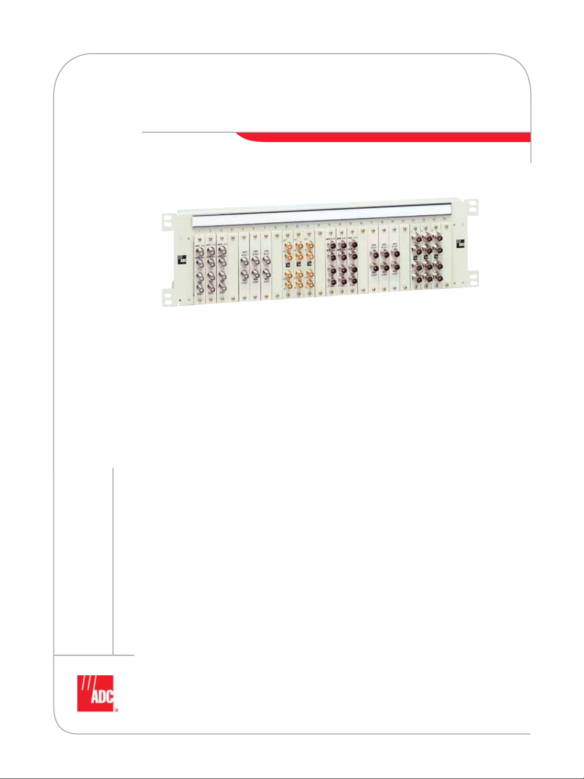
Designed as a flexible solution for network signal management, ADC’s Digital Monitor Module
(DMM) system provides a centralized coaxial termination and interconnection point between
network elements (NE). The DMM system allows a permanent, dedicated connection between
two NEs while providing dual, nonintrusive test access points for bidirectional monitoring of
the network signal. Ensuring unsurpassed quality, this interconnect solution features cable
management designed to increase reliability, maintain signal flow, and allow easy cable
identification. To enhance network flexibility, the DMM system allows modules to be installed
in a chassis as network requirements increase.
Features:
• Provides bidirectional, nonintrusive signal testing
• Supports E1 (2.048 Mbps), E3 (34.368 Mbps), or STM-1 (155.52 Mbps) signal rate applications
• Modular design allows for capital investment to coincide with revenue growth
• Mounts in standard 600 mm bays
• Quality cable management and circuit identification markings
SPEC SHEET
www.adc.com • +1-952-938-8080 • 1-800-366-3891
Page 2
Digital Monitor Module System
75 Ohm Interconnect
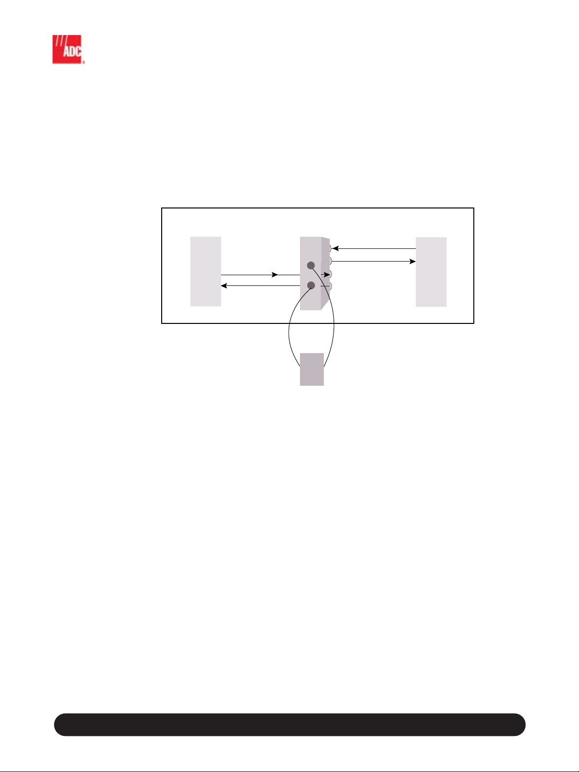
Application
The DMM system is used primarily in co-location environments, DDF locations, and customer premises
as a connection point between NEs. Each NE is semipermanently cabled to IN/OUT connectors in either
the front or rear of each module. The digital signal is accessed through the two MON OUT connectors
on the front of each module for testing and monitoring. These dual monitor ports allow access to both
directions of the circuit from a single location. This saves valuable technician time when the other side of
the termination is located far away, in another room, or is inaccessible.
Network
Element A
Tx OUT
Rx IN
DMM
MON
Z-OUT
MON
A-OUT
Test
Unit
OUT
IN
OUT
IN
Digital Monitor Module System
Network
Element Z
Tx OUT
Rx IN
12/06 • 103978AE
www.adc.com • +1-952-938-8080 • 1-800-366-3891
2
Page 3

Digital Monitor Module System
75 Ohm Interconnect
Configurations
The DMM system is available in several chassis and rack configurations to create a customized
interconnect solution. Each module is ordered separately and may be installed in any DMM chassis or
rack configuration as the network expands, allowing capital investment to coincide with revenue growth.
Modules
Multiple connector interface types and locations are available to complement existing network designs.
Individual modules allow chassis to easily match existing NE circuit counts.
Standard Configuration
Up to 12, 24-position chassis are designed to mount in a standard 600 mm rack for a total of 288
circuits. Cable management bars, trays, and labeling are provided on each chassis.
High-Density Configuration
This uniquely designed dual chassis features two separate compartments, each accommodating up to
eight modules mounted horizontally. The two compact compartments are mounted side-by-side in a
specially designed dual-column 600 mm rack. This high-density configuration allows a total of 352
circuits in one rack. Cable management bars and four vertical cabling ducts ensure proper routing for
high-density cabling.
Wall-Mount Box
This six-position enclosure serves as an interconnect demarcation point between network providers and
customers. Separate locks on each door secure connections from unwanted access.
Digital Monitor Module System
12/06 • 103978AE
www.adc.com • +1-952-938-8080 • 1-800-366-3891
3
Page 4

Digital Monitor Module System
75 Ohm Interconnect
Modules
Features:
• Front, dual monitor ports on all module styles
• BNC or 1.6/5.6 connectors provide true 75 Ohm characteristic impedance
• All module styles are compatable with any DMM 600 mm chassis style
Ordering Information
Description IN/OUT Connector Locations Catalog Number
BNC Rear DMM-BBNCMF
BNC Front and Rear DMM-BBNCF
BNC Bulkhead Front and Rear DMM-BNCBLK
1.6/5.6 Rear DMM-1656MF
1.6/5.6 Front and Rear DMM-1656F
1.6/5.6 Bulkhead Front and Rear DMM-1656BLK
Blank None DMM-BLANK
Digital Monitor Module System
DMM-BBNCMF
Rear and Front View
12/06 • 103978AE
DMM-1656MF
Rear and Front View
www.adc.com • +1-952-938-8080 • 1-800-366-3891
DMM-BBNCF
Rear and Front View
DMM-1656F
Rear and Front View
Rear and Front View
Rear and Front View
DMM-BNCBLK
DMM-1656BLK
4
Page 5

Digital Monitor Module System
75 Ohm Interconnect
Standard Configuration
Features:
• 288 total circuits in fully loaded bay
• Cable bars and front cable trays, with cable tie-downs, reduce
cable congestion and simplify maintenance
• Circuit designation labels above connectors and on cable
tray ensure proper cable routing and identification
• Bay equipped with cable troughs, vertical wiring ducts, and
equipment cable tie-down bars
• Zone 4 earthquake-rated rack with EIA mounting spacing
Ordering Information
Description Dimensions (HxWxD) Ordering Number
Unloaded Chassis
accomodates up to 24 modules
600 mm Skeleton Bay
accomodates up to 12 modules
113 x 482.6 x 228.6 mm
(4.4" x 19" x 9")
2200 x 600 x 475 mm
(86.6" x 23.6" x 18.7")
D3C-0024T
Front View
D3C-0024T
IBR-D3C001
600 mm
[23.6]
449.6 mm
[17.7]
45
RESERVED FOR
Digital Monitor Module System
2200 mm
[86.6]
12/06 • 103978AE
40
35
30
25
20
15
10
5
1
MISCELLANEOUS APPLICATIONS
UPPER CABLE
TROUGH
LOWER CABLE
TROUGH
475 mm
(18.7")
IBR-D3002
Front View
IBR-D3002
Side View
www.adc.com • +1-952-938-8080 • 1-800-366-3891
5
Page 6

Digital Monitor Module System
75 Ohm Interconnect
High-Density Configuration
Features:
• Improved circuit density by 20%; 352 circuits in
fully loaded bay
• Cable bars reduce cable congestion and simplify
maintenance
• Circuit designation label door ensures proper
cable routing and identification
• Bay equipped with four vertical cabling channels,
cable troughs, and equipment cable tie-down
bars for high density cable management
• Zone 4 earthquake-rated equal-flange rack with
EIA mounting spacing
Ordering Information
Description Dimensions (HxWxD) Ordering Number
Unloaded Pair of Dual Chassis
accomodates up to 16 modules in two, eight-position chassis
600 mm Dual Skeleton Bay
accomodates up to 11 dual chassis
88 x 236 x 165 mm
(3.5" x 9.3" x 6.5")
2200 x 600 x 250 mm
(86.7" x 23.6" x 23.6")
D3C-0016HD
Front View
D3C-0016HD
IBC-D3C001
Digital Monitor Module System
12/06 • 103978AE
IBC-D3001
Front View
www.adc.com • +1-952-938-8080 • 1-800-366-3891
IBC-D3001
Side View
6
Page 7

Digital Monitor Module System
75 Ohm Interconnect
Wall-Mount Box
Features:
• Used as a demarcation point when NEs are supplied by the
service provider and by the customer premises
• Seperate locks on each door secure connections from
unwanted access
D3C-WBOX06
Front View
Ordering Information
Description Dimensions (HxWxD) Ordering Number
Unloaded Wall-Mount Box
accomodates up to 6 modules
267 x 203 x 114 mm
(10.5" x 8" x 4.5")
D3C-WBOX06
Note: Modules are ordered seperately
Digital Monitor Module System
12/06 • 103978AE
www.adc.com • +1-952-938-8080 • 1-800-366-3891
7
Page 8

Specifications
ELECTRICAL
Insertion Loss Better than -.5 dB, 100 KHz to 100 MHz
Better than -.8 dB, 100 MHz to 300 MHz
Return Loss: Better than -20 dB, 100 KHz to 300 MHz
Monitor Loading Effect: < .4 dB change in insertion loss to 300 MHz
Monitor Level: 21.5 ± 1.5 dB, 100 KHz to 300 MHz
Isolation: < -55 dB at 22.368 MHz
Cross Talk: < -55 dB at 22.368 MHz
Phase Delay < 4 nanoseconds to 300 MHz
Pulse Template: Conform to CCITT Recomm. G.703
MECHANICAL
Retention Force: 7 lbs. minimum
Retention Torque: 4" per lbs. minimum
ENVIRONMENTAL
Thermal Shock: -40ºC to +60ºC operating
-55ºC to +85ºC non-operating
Moisture Resistance: 0% to 95%
SPEC SHEET
Web Site: www.adc.com
From North America, Call Toll Free: 1-800-366-3891 • Outside of North America: +1-952-938-8080
Fax: +1-952-917-3237 • For a listing of ADC’s global sales office locations, please refer to our web site.
ADC Telecommunications, Inc., P.O. Box 1101, Minneapolis, Minnesota USA 55440-1101
Specifications published here are current as of the date of publication of this document. Because we are continuously
improving our products, ADC reserves the right to change specifications without prior notice. At any time, you may
verify product specifications by contacting our headquarters office in Minneapolis. ADC Telecommunications, Inc.
views its patent portfolio as an important corporate asset and vigorously enforces its patents. Products orfeatures
contained herein may be covered by one or more U.S. or foreign patents. An Equal Opportunity Employer
103978AE 12/06 Revision © 2002, 2006 ADC Telecommunications, Inc. All Rights Reserved
 Loading...