

Page 1
Megabit Modem
Megabit Modem
Megabit Modem 400F, 500L, 600F, and
700F User Manual
Version 3.2.X
Catalog Number
MMD4090I1 Issue 1
Page 2

C
ht
opyrig
March 2001
©Copyright 2001 ADC DS L Syst em s, Inc. All Rights Reserved.
Trademark Information
ADC is a registered trademark of ADC Telecommunications, Inc.
Avidia and Megabit Modem are registered trademarks of PairGain Technologies, Inc. No right, license, or interest to
such tradema rks is g rante d here under , an d you ag ree t hat no such r ight, licen se, or inte rest s hall b e asser ted by you wi th
respect to such trademark.
Other product names ment ion ed in this practice are used for identification purposes only and may be tr ademarks or
registered trad em arks of their respect ive companies.
Disclaimer of Liability
Information contained in this document is company private to ADC DSL Systems, Inc., and shall not be modified, used,
copied, reproduced or disc lose d in whole or in part without the wr it te n consent of ADC.
Contents herein are current as of the dat e of publication. ADC res erves the right to change the contents wi thout prior
notice. In no event shall ADC be liab le for any damages resulting from loss of data, loss of use, or loss of profits, a nd
ADC further disclaims any and all liability for indirect, incidental, special, consequential or other similar damages. This
disclaimer of liability applie s to a ll products, publications and services during and after the warranty period.
ii Megabit Modem 400F, 500L, 600F, and 700F User Manual
Page 3

About This User Manual
ABOUT THIS USER MANUAL
Use this manual to install and configure the Megabit Modem® 400F, 500L, 600F, and 700F.
This manual provides instruction on:
• information you will need to configure the modem
• unpacking and inspecting the modem for installation
• installing the modem
• setting up parameters for your applications that will be used to configure the modem
• configuring system parameters
• configuring sessions between the modem and a service provider
• monitoring and troubleshooting the modem
Chapter 10 provides a reference for the technology implemented in the Megabit Modem 400F,
500L, 600F, and 700F. This chapter covers information about ATM over ADSL transmission,
operating modes of PPP or bridging/routing, and SNMP management.
IP addresses used in this manual are for example only. You will acquire your own addresses
from the service provider and your information services coordinator to configure the Megabit
Modem 400F, 500L, 600F, and 700F. However, you will use the IP address specified in
“Accessing the Modem Web Pages” on page 27 to access the Megabit Modem 400F, 500L,
600F, and 700F from a Web browser.
DOCUMENT CONVENTIONS
Two types of messages, identified by icons, appear in the text.
Notes contain information about special circumstances.
Cautions indicate the possibility of equipment damage or the possibility of
personal injury.
Megabit Modem 400F, 500L, 600F , and 700F User Manual iii
Page 4

Product Cer tifications
PRODUCT CERTIFICATIONS
FCC Class B Compliance
This equipment has been tested and f ound to comply with the limits for a Class B d igital device,
pursuant to part 15 of the FCC Rules. These limits are designed to provide reasonable protection
against harmful interference in a residential installation. This equipment generates, uses and can
radiate radio frequency energy and, if not ins talled and used in accordance with the instructions,
may cause harmful interference to radio communications. However, there is no guarantee that
interference will not occur in a particular installation.
If this equipment does cause harmf ul interference to rad io or television reception, which can be
determined by turning the equipment off and on, the user is encouraged to try to correct the
interference by one or more of the following measures:
• Reorient or relocate the receiving antenna.
• Increase the separation between the equipment and receiver.
• Connect the equipment into an outlet on a circuit different from that to which the receiver
is connected.
• Consult the dealer or an experienced radio/TV technician for help.
UL
This product meets all safety requirements per UL-1950 standard.
CE
This product meets all EMC and safety requirements per EN 300 386-2 and IEC 950
(EN60950).
iv Megabit Modem 400F, 500L, 600F, and 700F User Manual
Page 5

Table of Contents
TABLE OF CONTENTS
Chapter 1: About The Product...............................................................................................1
Megabit Modem 400F.........................................................................................................2
Megabit Modem 500L.........................................................................................................4
Megabit Modem 600F.........................................................................................................5
Megabit Modem 700F.........................................................................................................6
Chapter 2: What You Need To Start.....................................................................................9
Verify Package Contents.....................................................................................................9
Requirements For Your System ........................................................................................10
Requirements For The Installation Site.............................................................................10
Location for Modem Installation ........................................................................10
Phone Service......................................................................................................13
What You Need from Your Service Provider...................................................................13
What You Will Choose .....................................................................................................14
Configuration ......................................................................................................14
Power Cable................................................................... .....................................14
Chapter 3: Installing the Modem.........................................................................................15
Attaching the Feet..............................................................................................................16
Setting the MDI/MDI-X Switch........................................................................................17
Installing Cabling ..............................................................................................................18
Setting Up ADSL Service .................................................................................................20
Checking LED Indications................................................................................................20
Connecting Phone Service.................................................................................................21
Chapter 4: Setting Up For Configuration...........................................................................23
Setting Up the PC To Configure the Modem....................................................................24
Configuring a Web Browser..............................................................................................25
Accessing the Modem Web Pages.....................................................................................27
Saving the Configuration...................................................................................................28
Megabit Modem 400F, 500L, 600F , and 700F User Manual v
Page 6

Table of Cont en t s
Saving the Configuration to NVRAM.................................................................29
Resetting the Modem...........................................................................................30
Resetting the Modem to Factory Defaults...........................................................31
Chapter 5: Configuring System Settings .............................................................................35
Defining TFTP Parameters................................................................................................36
Defining SNMP Parameters...............................................................................................38
Defining Static NAT Entries..............................................................................................40
Configuring Static MAC Entries.......................................................................................42
Display Static MAC Entries................................................................................42
Add a Static MAC Entry.....................................................................................42
Modify a Static MAC Entry................................................................................42
Delete a Static MAC Entry..................................................................................43
Configuring Static Routes..................................................................................................44
Display Static Routes ..........................................................................................44
Add a Static Route...............................................................................................44
Modify a Static Route..........................................................................................44
Delete a Static Route...........................................................................................45
Configuring System Security.............................................................................................46
Admin IP Address...............................................................................................46
RS-232 MGMT Port............................................................................................47
Selecting the System Mode of Operation..........................................................................48
Chapter 6: Configuring PPP Sessions..................................................................................51
Selecting Configuration Parameters..................................................................................52
Setting Up the PPP Mode (700F Only) .............................................................................52
Configuring the WAN PPP Sessions.................................................................................53
Add a PPP over ATM WAN Session..................................................................54
Modify a PPP over ATM WAN Session.............................................................57
Delete a PPP over ATM WAN Session ..............................................................57
Configuring the LAN.........................................................................................................58
vi Megabit Modem 400F, 500L, 600F , and 700F User Manual
Page 7

Table of Contents
Configure Modem Parameters ............................................................................58
Saving the Configuration....................................................................................59
Assigning LAN Users to PPP Sessions............................................................................. 60
Add a User Assignment ......................................................................................60
Delete a User Assignment:..................................................................................61
Activating and Deactivating Sessions...............................................................................62
Chapter 7: Configuring Bridging/Routing Sessions...........................................................63
Setting Up the Bridging/Routing Mode (700F Only)........................................................64
Configuring the WAN Bridging/Routing Sessions...........................................................65
Add a Bridging/Routing WAN Session..............................................................66
Modify a Bridging/Routing WAN Session.........................................................68
Delete a Bridging/Routing WAN Session...........................................................68
Configuring the LAN ........................................................................................................69
Configure Modem Parameters ............................................................................69
Saving the Configuration....................................................................................70
Activating and Deactivating Sessions...............................................................................71
Chapter 8: Viewing Statistics ...............................................................................................73
Viewing ADSL Status ...................................... ..... ............................................................73
Viewing Network Statistics.......................................................... .....................................75
LAN Statistics.....................................................................................................75
WAN Statistics....................................................................................................76
Chapter 9: Maintenance and Troubles hooting...................................................................77
Maintenance ......................................................................................................................77
Updating Software ..............................................................................................77
Using the RS-232 Management Port................................................................... 80
Setting Up the PC to Request an IP Address.....................................................................83
Troubleshooting.................................................................................................................84
Chapter 10: Technical Reference.........................................................................................85
Transmission on the Wide Area Network.........................................................................85
Megabit Modem 400F, 500L, 600F , and 700F User Manual vii
Page 8

Table of Cont en t s
ADSL...................................................................................................................85
ATM....................................................................................................................86
System Mode Encapsulation..............................................................................................87
PPP ......................................................................................................................87
Bridging...............................................................................................................88
Routing................................................................................................................90
Encapsulation for RFC 1483 Bridging/Routing..................................................90
Management Protocols ................................................. ..... ................................................91
SNMP..................................................................................................................91
MIB and Trap Support ........................................................................................92
DNS Resolution.................................................................................................................93
TFTP Server.......................................................................................................................93
Appendix A: Specifications and Data ...................................................................................95
WAN Interface Specifications...........................................................................................95
Encapsulation.....................................................................................................................96
LAN Interface....................................................................................................................97
Physical Specifications......................................................................................................97
Power Supply.................................... ....................................... ..........................................97
Environmental....................................................................................................................97
Compliance........................................................................................................................98
RFCs ..................................................................................................................................98
MIBs ..................................................................................................................................98
Rate vs. Reach....................................................................................................................99
Hardware..........................................................................................................................100
Installation Kit.......................................... ...... ..... ..............................................100
Connector Pinouts .............................................................................................101
Appendix B: Technical Assistance and Returns................................................................103
Technical Support............................................................................................................103
World Wide Web.................................................... .........................................................103
viii Megabit Modem 400F, 500L, 600F , and 700F User Manual
Page 9

Table of Contents
Advance Replacement.....................................................................................................103
Billing..............................................................................................................................104
Returns.............................................................................................................................105
Appendix C: Configuration Worksheets............................................................................107
Appendix D: Glossary ..........................................................................................................117
Megabit Modem 400F, 500L, 600F , and 700F User Manual ix
Page 10

Table of Cont en t s
x Megabit Modem 400F, 500L, 600F, and 700F User Manual
Page 11

ABOUT THE PRODUCT
You have purchased the Mega bit Modem® that connects
your Ethernet LAN to service providers for instant and
high-speed access to the Internet or to other types of Wide
Area Network (WAN) applications. It uses Asymmetric
Digital Subscriber Line (ADSL) technology to give you
broadband access over existing cabling in your home,
office, or building.
The Megabit Modem is easy to install and configure. To
install the modem:
• connect a telephone cable from the modem to a wall phone jack for ADSL service
• connect a cable from the modem to a PC or an Ethernet hub for LAN service
• connect a power cable to a local power source
To access the modem configuration, you launch your Web browser and enter the modem IP
address as the URL. Use the modem Web pages to:
• configure ADSL, LAN, and WAN parameters
• view ADSL, IP, LAN, and WAN statistics
1
• upgrade software
• define SNMP parameters
• perform a syste m reset
• define static MAC, NAPT, and route tables
In addition, the LEDs on the modem front panel provide continual s tatus at-a-glance for network
and modem connections.
The following sections list the Megabit Modem 400F, 500L, 600F, and 700F features and
applications.
Megabit Modem 400F, 500L, 600F , and 700F User Manual 1
Page 12

Megabit Modem 400F
MEGABIT MODEM 400F
The Megabit Modem 400F is designed for LAN applications and offers these features:
• supports full-rate ADSL and G.lite
• offers rates up to 7.552 Mbps downstream and 928 kbps upstream for full rate
• offers rates up to 1.5 Mbps downstream and 512 kbps upstream for G.lite
• offers symmetric rates up to 928 kbps
• supports 1483 bridging and routing over ATM
• supports up to 32 Bridge/Router sessions
• contains an embedded SNMP agent
• operates as a DHCP server
• supports NAT (including NAPT) and DNS
See the illustration on the next page for an application example.
2 Megabit Modem 400F, 500L, 600F, and 70 0F User Manual
Page 13

Chapter 1: About The Product
i
Bus
ness Internet Access
ADSL
400F
Megabit Modem 400F, 500L, 600F , and 700F User Manual 3
Internet
Page 14

Megabit Modem 500L
MEGABIT MODEM 500L
The Megabit Modem 500L is a rate adaptive G.lite modem for single user applications and
offers these features:
• complies with the G.lite standard
• offers rates up to 1.5 Mbps downstream and 512 kbps upstream
• supports RFC 2364 PPP over ATM ( AAL 5)
• supports up to 8 sessions
• contains an embedded SNMP agent
• operates as a DHCP server
• supports NAT (including NAPT) and DNS
Microfilter
ADSL
500L
4 Megabit Modem 400F, 500L, 600F, and 70 0F User Manual
Internet
Page 15
Chapter 1: About The Product
MEGABIT MODEM 600F
The Megabit Modem 600F is a high-performance ADSL modem designed for power users. It
offers these features:
• supports full-rate ADSL and G.lite
• offers rates up to 7.552 Mbps downstream/928 kbps upstream for full rate
• offers rates up to 1.5 Mbps downstream/512 kbps upstream for G.lite
• offers symmetric rates up to 928 kbps
• supports RFC 2364, carrying PPP traffic over ATM (AAL5)
• supports 32 PPP sessions
• contains an embedded SNMP agent
• operates as a DHCP server
• supports NAT (including NAPT) and DNS
600F
POTS
Splitter
Provider
Network
Megabit Modem 400F, 500L, 600F , and 700F User Manual 5
Page 16

Megabit Modem 700F
MEGABIT MODEM 700F
The Megabit Modem 700F is designed as an ADSL router for LAN applications.
• supports full-rate ADSL and G.lite.
• offers rates up to 7.552 Mbps downstream/928 kbps upstream for full rate
• offers rates up to 1.5 Mbps downstream/512 kbps upstream for G.lite
• offers symmetric rates up to 928 kbps
• supports RFC 2364 PPP traffic over ATM (AAL5)
• supports 1483 bridging and routing over ATM
• supports up to 32 sessions in PPP O ver ATM mode or
supports up to 32 sessions in Bridge/Router mode
• contains an embedded SNMP agent
• operates as a DHCP server
• supports NAT (including NAPT) and DNS
See the illustration on the next page for an application example.
6 Megabit Modem 400F, 500L, 600F, and 70 0F User Manual
Page 17
Chapter 1: About The Product
i
Large Bus
ness Internet Access
ADSL
700F
Megabit Modem 400F, 500L, 600F , and 700F User Manual 7
Internet
Page 18

Megabit Modem 700F
8 Megabit Modem 400F, 500L, 600F, and 70 0F User Manual
Page 19
WHAT YOU NEED TO START
This chapter identifies the preparations and prerequisites for installing the Megabit Modem
400F, 500L, 600F, and 700F. Before installing the modem, verify that:
• The contents of the package are accurate as described on this page.
• Your system meets the requirements for connecting to and configuring the modem
(see “Requirements For Your System” on page 10).
• Your facility meets the installation site requirements (see “Requirements For The
Installation Site” on page 10).
• The configuration parameters are available from your service provider (see “What You
Need from Your Service Provider” on page 13).
VERIFY PACKAGE CONTENTS
As you unpack your Megabit Modem, visually inspect the contents for signs of damage. If the
equipment was damaged in transit, report the damage to the transportation company and to the
sales representative.
Check the contents of the package for the
following:
2
• one black cable
• one grey phone cord
• four rubber, self-adhesive feet
• two screws
• power supply and optiona l power cord
(see “Power Cable” on page 14 for options)
• grey cable and DB-9 console port adapter
If you need to store the modem for a prolonged period, store it in the original antistatic bag
and packaging. Observe environmental specifications as stated on page 97.
Megabit Modem 400F, 500L, 600F , and 700F User Manual 9
Page 20

Requirements For Your System
REQUIREMENTS FOR YOUR SYSTEM
You need the following hardware and software to complete the installation and configuration of
the Megabit Modem 400F, 500L, 600F, and 700F:
• PC with an Ethernet Network Interface Card (NIC)
• TCP/IP network protocol stack (see the operating system documentation)
• Web browser installed such as Netscape
• Ethernet hub (optional )
®
or Internet Explorer® Version 4.0 or higher
REQUIREMENTS FOR THE INSTALLATION SITE
Before installing the Megabit Modem 400F, 500L, 600F, and 700F, you must:
• select a location to install the modems as described in the sectio n below
• identify requirements to connect phones as described in the section “Phone Service” on
page 13
Location for Modem Installation
You can install the modem either:
• placed on a flat surface (shown on page 11)
• mounted on a wall (shown on page 12)
Your facility must have the following minimum site requirements to install each modem:
• power outle t
• RJ-11 wall jack that has DMT ADSL service available
10 Megabit Modem 400F, 500L, 600F, and 700F User Manual
Page 21
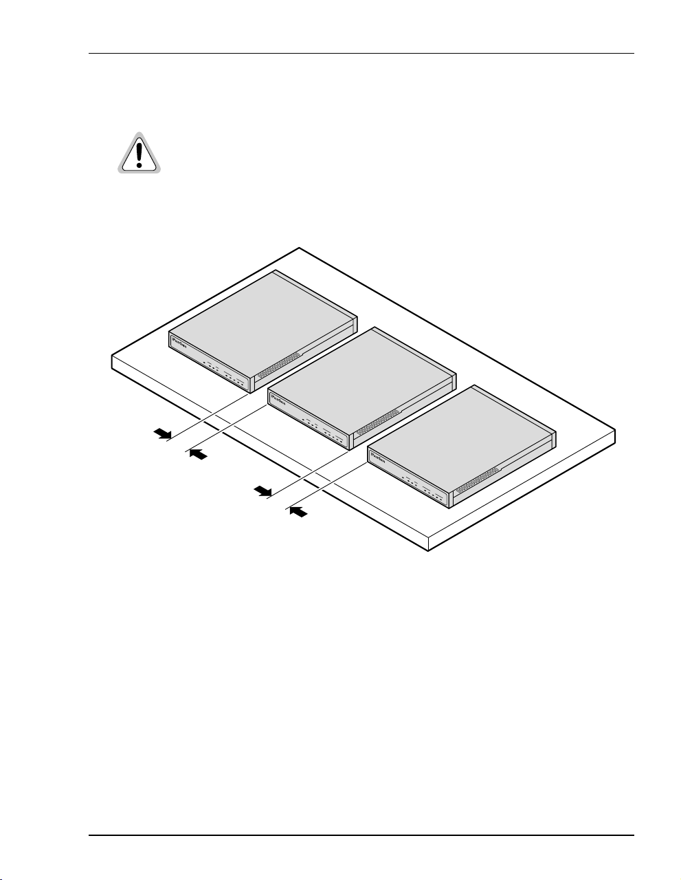
Flat-Surface Mount
Do not stack the mode ms when installing on a flat surface. The modems do not
dissipate heat properly when stacked.
Place the modems on a flat surface, such as on a table or in a rack.
PWR LINK TX RX
LAN
MEGABIT
MODEM
SYNC
TX
ADSL
7
RX MAR
00F
OH
PWR LINK TX RX
LAN
MEGABIT
MODEM
SYNC
TX RX MAR
ADSL
7
00F
OH
Minimum
1-inch clearance
Minimum
1-inch clearance
PWR LINK TX RX
LAN
MEGABIT
MODEM
SYNC
TX RX MAR
ADSL
7
00F
OH
Chapter 2: What You Need To Start
Megabit Modem 400F, 500L, 600F , and 700F User Manual 11
Page 22
Requirements For The In stallation Site
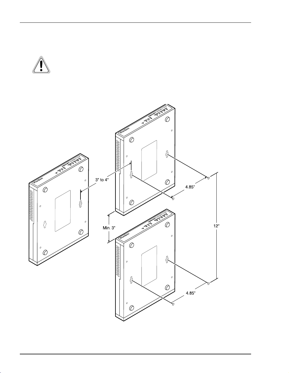
Wall Mount
Observe the minimum dimensions between multiple modems (shown in the
illustration) to ensure sufficient ventilation for heat dissipation
Mount the Megabit Modem on a wall using the two screws included with the modem.
12 Megabit Modem 400F, 500L, 600F, and 700F User Manual
Page 23

Chapter 2: What You Need To Start
Phone Service
If you get phone service with your data service, you need the following:
• S1 Network Interface Device (or other POTS splitter) installed by your service provider
• RJ-11 phone jacks for phone service
The POTS splitter is a device that separates data transmission from ph one ser vice. After
installing the POTS splitter, connect separate jacks for data and for phone service. Ensure that
your service provider indicates which jacks are for data and which jacks are for phone service.
WHAT YOU NEED FROM YOUR SERVICE PROVIDER
This section lists the information you need to configure system settings an d sessions for the
modem. Contact your service provider for this information. Use the worksheets, provided in
Appendix C on page 107, to record your configuration information. When you b e gin to
configure the modem in Chapter 4 on page 23, the procedures refer you to the proper table for
the configuration information that you recorded.
1 System mode (WAN connection for the sessions between the modem and the service
provider): PPP over ATM or Bridge/Router RFC 1483
2 If Bridge/Router:
• Configure as a Bridge only, as a Router only, or as a Bridge and Router.
• If Bridge or Router, choose LLC or VC-MUX encapsulation.
• If Router, choose the version of and direction for RIP (RIP1, RIP2, or RIP1
compatible).
• If Bridge, select whether or not to enable Spanning Tree.
3 If PPP over ATM and using CHAP, identify CHAP authentication name.
4 Session addre ss for Ports 1 through 32 (WAN c onfiguration):
• ATM VPI and ATM VCI (specified for each session)
• when using fixed IP addresses, IP address specified for each session by the
service provider
• for PPP system mode, Login Name and Login Password (specified for each session)
For more information about the configuration ch oices listed above, s ee Chapter 10, “Technical
Reference” on page 85.
Megabit Modem 400F, 500L, 600F , and 700F User Manual 13
Page 24

What You Will Choose
WHAT YOU WILL CHOOSE
Before configuring the modem, consider the options in the following “Configuration” section.
Ensure that you have the appropriate power cable for your facility as described below in the
“Power Cable” section.
Configuration
You can choose to use:
• Network Address Translat ion (NAT) prot ocol. This protocol incl udes both basi c NAT and
Network Address Port Translaton (NAPT). Basic NAT uses a one-to-one mapping of a
private IP address and a public IP address. NAPT uses a multiple-to-one mapping of
multiple IP addresses and their ports to a single IP address and its ports. For more
information about the NAT protocol, see “NAT” on page 87.
• Domain Name System (DNS) resolution. You must specify the IP address for a device to
serve as the DNS resolver. You can also specify a second IP address to designate another
device to serve as a secondary DNS resolver. The DNS device maps human-readable
addresses to IP addresses. For simplicity and ease of management, use DNS relay. DNS
relay allows the LAN hosts to configure the Megabit Modem as the DNS server. Depending
on the host sending the DNS message and what session it is assigned to, the Megabit
Modem will relay the message to the appropriate DNS server. For more information about
DNS resolution, see “DNS Resolution” on page 93.
• TFTP server for downloading sof tware updates to the modem. Yo u specify th e IP address,
subnet mask, and directory path (where software updates are located) for the device that
will be the TFTP server.
Power Cable
The Megabit Modem 400F, 500L, 600 F, and 700F are available with a variet y of power supplies
and power cords. When you order your mod em, choose one of the following as the last num ber
in the product part number (example: use 150-2122-7x for the 700F) for your order to ind icate
which power option you need:
• 2 indicates a power supply for International use and does not include a power cord.
• 3 indicates a power supply for North American use and includes a North American
power cord.
• 4 indicates a Universal power supply and includes a European power cord.
• 5 indicates a Universal power supply and includes a UK/Ireland power cord.
14 Megabit Modem 400F, 500L, 600F, and 700F User Manual
Page 25

INSTALLING THE MODEM
The Megabit Modem is easy to install by:
• attaching the four adhesive-backed feet
• setting the MDI/MDI-X switch
• connecting a cable from the modem to a PC or an Ethernet hub for LAN service
• connecting a phone cord from the modem to a wall phone jack for DMT ADSL Internet
or other types of WAN services
• connecting a power cable to a local power outlet
Perform the installation on the following pages (see “Requirements For The Installation Site”
on page 10 to determine where to place modems). Use the parts listed below in the installation
procedures.
Part Function
Installation Kit
Rubber feet (four) Attaches to the base of the modem.
Black cable Connects the modem 10/100BASE-T connector to the LAN through a hub
or to a PC NIC. This cable is a straight-through Category 5 cable.
Grey cord Connects the modem ADSL connector to the RJ-11 wall jack with DMT
ADSL service for access to the Internet or other types of WAN applcations.
Power cable Connects the modem POWER connector to the local power source. Power
supply optionally has a power cord. (See “Power Cable” on page 14 for
selection options.)
3
Not In Installation Kit (in ship box)
Grey cable and
adapter
Megabit Modem 400F, 500L, 600F , and 700F User Manual 15
Connects the RS-232 MGMT port to an ASCII terminal or a PC running
terminal emulation software. Adapter assembly connects to a DB-9
connector on the PC. Then, one RJ-45 connector installs in the adapter and
the other connector into the console port on the modem.
Page 26
Attaching the Feet
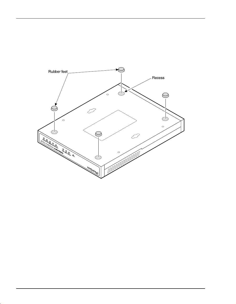
ATTACHING THE FEET
Attach each of the four adhesive-backed rubber feet to a footprint recess on the bottom of
the modem.
16 Megabit Modem 400F, 500L, 600F, and 700F User Manual
Page 27

Chapter 3: Installing the Modem
SETTING THE MDI/MDI-X SWITCH
Using the MDI/MDI-X switch, the Megabit Modem can communicate with a device on the
LAN that is either MDI or MDI-X without having to change the cable (a straight-through cable
is supplied with the installation kit).
Set the switch for the 10/100BASE-T port to either:
• MDI-X when you are connecting to a device with a MDI port such as a PC with an
Ethernet NIC
• MDI when you are connecting to a device with a MDI-X port such as a hub, repeater,
bridge, or router
For connection to
devices such as
a PC
MDI-X
For connection to
MDI
devices such as
a hub
10/100BASE-T
Megabit Modem 400F, 500L, 600F , and 700F User Manual 17
RS232 MGMTMDI MDI-X
ADSL POWER
Page 28
Installing Cabling
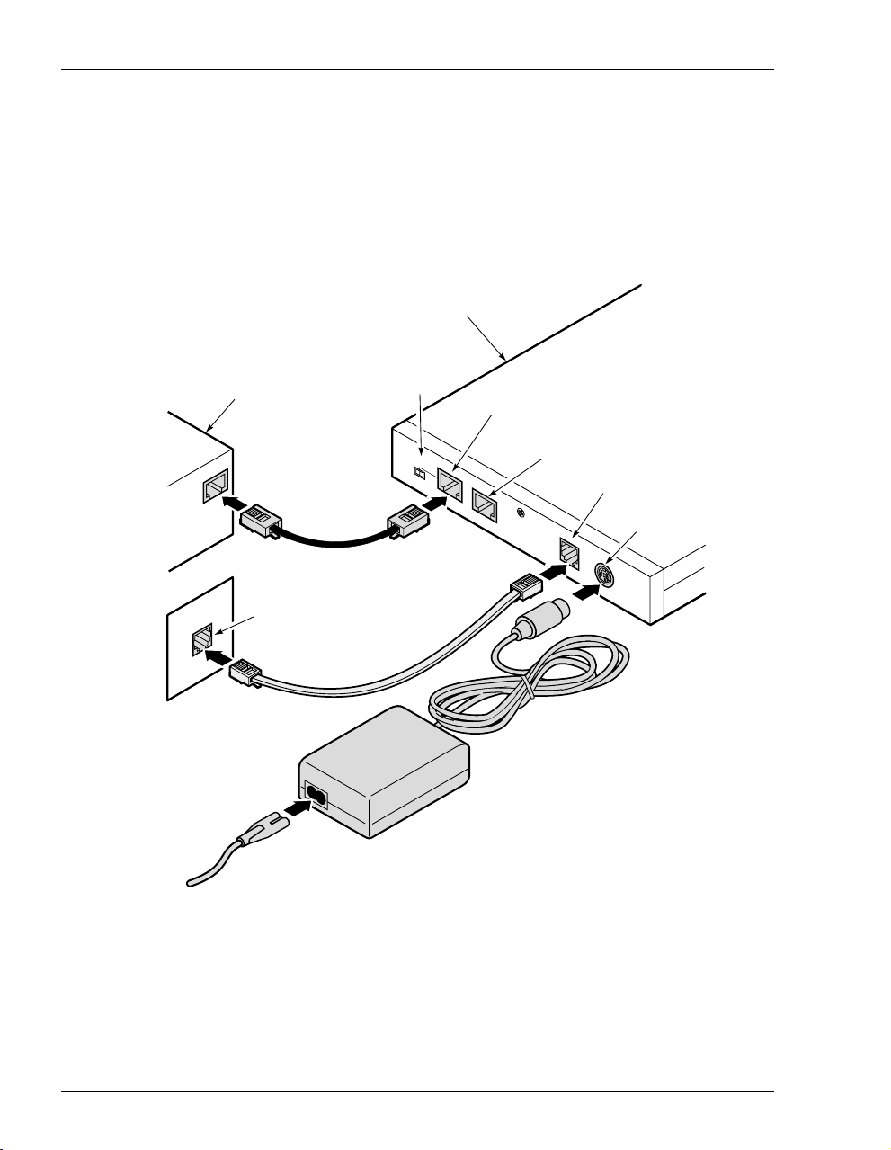
INSTALLING CABLING
Install the black cable for the 10/100BASE-T LAN connection, the grey phone cord for the
ADSL port WAN connection, and the power cable to the power connector (cable specified on
page 14).
.
Megabit Modem
To power
outlet
PC, hub or other
network device
Wall jack with DMT ADSL
service
Switch
MDI MDI-X
10/100BASE-T port
10BASE-T
RS232
M
GMT
RS-232 MGMT port
(600F and 700F only)
ADSL port
Power
connector
D
S
L
P
O
W
E
R
18 Megabit Modem 400F, 500L, 600F, and 700F User Manual
Page 29

Chapter 3: Installing the Modem
1 After you have set the MDI/MDI-X switch to the correct position, connect the black cable
from the modem 10/100BASE-T port to your PC or hub.
2 Connect the grey phone cord from the modem ADSL port to the ADSL wall jack. If your
installation requires a splitter or microfilter, refer to the manufacturer’s documentation for
further instructions.
3 Connect the power cable from the modem power connector to a power outlet.
If you need pinouts fo r the ADS L and 10 /100BAS E-T connec tors , see “Connector Pinouts” on
page 101. For information on how to use the RS-232 m a nagement port for maintenance, see
“Using the RS-232 Management Port” on page 80.
Megabit Modem 400F, 500L, 600F , and 700F User Manual 19
Page 30

Setting Up AD SL Service
SETTING UP ADSL SERVICE
The service provider sets up the ADSL parameters for your service. The modem must have
the ADSL SYNC LED lit before you can connect sessions with your service provider. Verify
SYNC in the following section, “Checking LED Indications.”
CHECKING LED INDICATIONS
The table below describes LED indications for all operational modes. LEDs on the modem front
panel prov ide continual status at- a-glance for network and modem connections.
LED State Description
PWR On green Modem has power.
Off Modem does not have power.
LAN
LINK On green A PC, hub, or other network device is connected to the modem
Off No device is connected to the modem 10/100BASE-T interface.
TX Flashing green Modem is transmitting data to devices on the LAN.
Off Modem is not transmitting data to the LAN.
RX Flashing green Modem is receiving data from devices on the LAN.
Off Modem is not receiving data from the LAN.
SYNC On green ADSL transceiver is synchronized and in normal operation mode.
Flashing green ADSL transceiver is in a start-up sequence.
Off ADSL modem transceiver is not detecting a transceiver at the far end.
TX Flashing green Modem is transmitting data to the service provider.
Off Modem is not transmitting data to the service provider.
RX Flashing green Modem is receiving data from the service provider.
Off Modem is not receiving data from the service provider.
MAR On green ADSL margin is at or above the value set by the service provider.
Off ADSL margin is below the value set by the service provider.
OH On yellow Telephone receiver is off hook.
Off Telephone receiver is on hook.
10/100BASE-T interface.
ADSL
20 Megabit Modem 400F, 500L, 600F, and 700F User Manual
Page 31

Chapter 3: Installing the Modem
CONNECTING PHONE SERVICE
The Megabit Modem 400F, 500L, 600F, and 700F modem provide full support for the ITU
standard G.hs, G.dmt, and G.lite. In the traditional ADSL deployment, POTS splitters are
required to separate data transmission from phone service. In this case, the service provider will
supply you with a splitter. You will have one or more jacks for phone service and one jack for
ADSL data service. Connect your phones to the jacks indicated by the service provider for
phone service. However, using G.lite allows for splitterless deployment. In this case, you will
not need to install a splitter.
Megabit Modem 400F, 500L, 600F , and 700F User Manual 21
Page 32

Connecting Phone Serv ic e
22 Megabit Modem 400F, 500L, 600F, and 700F User Manual
Page 33

SETTING UP FOR CONFIGURATION
Set up a PC and a Web browser to co nfigure th e Megabit Modem 40 0F, 500L, 6 00F, and 700F .
This chapter provides the set up procedures, then shows you how to access and navigate the
Megabit Modem Web pages. The configuration process flow is shown below.
Start
Setting Up the PC To Configure
the Modem
Chapter 4 on page 24
4
500L, 600F, and 700F
Configuring PPP over ATM Sessions
• Configuring the WAN PPP
Sessions
• Configuring the LANClick Apply.
• Activating and Deactivating
Sessions
Configuring a Web Browser
Accessing the Modem Web Pages
Configuring System Settings
• Defining TFTP Parameters
• Defining SNMP Parameters
• Configuring System Security
• Selecting the System Mode of
Operation
Configuring Bridging/Routing
Sessions
OR
Chapter 4 on page 25
Chapter 4 on page 26
Chapter 5 on page 35
400F and 700F
• Configuring the WAN
Bridging/Routing Sessions
• Configuring the LAN
• Activating and Deactivating
Sessions
Megabit Modem 400F, 500L, 600F , and 700F User Manual 23
Page 34

Setting Up the PC To Configure the Modem
SETTING UP THE PC TO CONFIGURE THE MODEM
Set up your PC to be on the same IP subnet as the modem. Since the m odem default uses DHCP,
it will automatically configure your IP settings once you set up that option. If you want to view
or change the default IP address for the modem, see “Using the RS-232 Management Port” on
page 80.
The following is an example of how to set up a PC running Microsoft Windows 98.
1 Open the
2 From the Configuration tab, double-click
3 If DHCP has been enabled on the modem (default), select
address automatically
4 Enter
Control Panel then double-click the Network icon.
TCP/IP.
Obtain an IP
and skip to step 5. Otherwise, select Specify an IP address.
IP Address and Subnet Mask. The default LAN IP address i s 192.168.0.1. Use an IP
address from the following rang e: 192 .16 8.0. 2 t o 19 2.1 68. 0.25 4. The default subnet mask
is 255.255.255.0.
5 Click
6 Click
7 Click
OK to close the TCP/IP Properties window.
OK to close the Network window.
OK to restart the computer.
24 Megabit Modem 400F, 500L, 600F, and 700F User Manual
Page 35

Chapter 4: Setting Up For Configuration
CONFIGURING A WEB BROWSER
Access the Megabit Modem Web page through a Web browser (see page 10 for Web browser
versions supported). The Web browser must have the proxies disabled and cache settings
enabled to compare the cached document against the network document every time it is
accessed.
The following is an example of how to make the configuration changes using Netscape
Navigator 4.0.
1 Open your Web browser.
2 Click
3 From Category, select
4 From Category, select
5 Click
Edit, Preferences to open the Preferences dialog.
OK to close the Preferences window.
Advanced, click Cache, then select Every time.
Advanced, click Proxies, then select Direct connection to the Internet.
Megabit Modem 400F, 500L, 600F , and 700F User Manual 25
Page 36

Configur i ng a Web Browser
The following is an example of how to make the configuration changes using
Internet Explorer 5.5:
1 Open your Web browser.
2 Click
3 In the
4 Select
Tools, Internet Options to open the Internet Options dialog.
Temporary Internet Files section of the dialog, click Settings.
Every visit to the page, then click OK.
5 Click the
6 In the
7 Click
8 Click
Proxy Server section of the dialog, clear the Use a proxy server box.
OK to close the LAN Settings dialog.
OK to close the Internet Options dialog.
Connections tab, then click LAN Settings to open the LAN Settings dialog.
26 Megabit Modem 400F, 500L, 600F, and 700F User Manual
Page 37

Chapter 4: Setting Up For Configuration
ACCESSING THE MODEM WEB PAGES
Type http://192.168.0.1 in the Location Bar field of the Web browse r (as shown below), then press
. (192.168.0.1 is the default IP address for the Ethernet port and is a private address
ENTER
specified for use by RFC 1918. If you change the Ether net IP address th rough the manag ement
port, you will enter the new IP address in the
http://192.168.0.1/index.htm
By default, the Megabit Modem
(except the 400F) initializes in
“PPP over ATM” mode and
displays the page to the top right:
Location Bar.)
Location Bar
If the Megabit Modem is in
“Bridging/Routing” mode, it
displays this page:
Megabit Modem 400F, 500L, 600F , and 700F User Manual 27
Page 38

Saving the Configuration
SAVING THE CONFIGURATION
Save the majority of the configuration changes by the clicking Apply. However, there are other
configuration changes that require you to reset the modem in order to update NVRAM with
these modifications. These changes are described in the following table:
Item Menu Tab
System Mode system general
LAN IP Address and Net Mask lan general
DHCP IP Address Range lan general
RIP Version lan general
See the following sections to:
• save configuration changes to NVRAM on page 29
• reset the modem to activate the configuration on page 30
• reset the modem to restore the factory default values on page 31
28 Megabit Modem 400F, 500L, 600F, and 700F User Manual
Page 39

Chapter 4: Setting Up For Configuration
Saving the Configuration to NVRAM
After clicking Apply at the bottom of a configuration page, the chang es are automatically saved
to NVRAM. Changes may either take effect immediately or after system reset.
To the right is an example of a
configuration change (TFTP server IP
address) that only requires you to
Apply for changes to take effect
click
immediately (commit changes to
RAM) and be saved to NVRAM.
Below is an example of a
configuration change (LAN IP
address) that requires both the click of
Apply at the configuration screen and a
system reset for changes to take effect
and to be saved to NVRAM.
1 Locate Apply at the bottom of the
dialog.
2 Click
Apply to open the
confirmation dialog.
3 Click OK to reset the modem.
Megabit Modem 400F, 500L, 600F , and 700F User Manual 29
Page 40

Saving the Configuration
Resetting the Modem
Resetting the modem causes all active connections to drop.
After you make changes to the modem configuration and write the changes to NVRAM or
return modem configuration to factory defaults, you must reset the modem. See page 28 for
a list of changes that you must reset to effect.
1 From the
2 Click
system menu, click general to open the General System window.
Reset Unit.
3 Click Proceed to reset the modem.
30 Megabit Modem 400F, 500L, 600F, and 700F User Manual
Page 41

Chapter 4: Setting Up For Configuration
Resetting the Modem to Factory Defaults
You can return the Megabit Modem parameters to the factory default values. This provides
a known starting point if you are troubleshooting the system or simply need to reconfigure
parameters. The factory default values are listed on page 32 and page 33.
1 From the
2 Click
system menu, click general to open the General System window.
Set Factory Default.
When you click Proceed to return to factory default values, the modem
automatically resets.
3 Click Proceed to return to factory default values.
Megabit Modem 400F, 500L, 600F , and 700F User Manual 31
Page 42

Saving the Configuration
Listed in the table below are the default values for the Megabit Modem in PPP over ATM mode.
Reference this table to learn the values assigned to the modem after resetting it to factory
default.
Parameter Default Value Parameter Default Value
System Setup
System Mode PPP over ATM SNMP parameters
TFTP parameters Enable trap sending Not enabled
TFTP Server IP Address 192.168.0.2 Trap Server IP Address 0.0.0.0
TFTP Server Net Mask 255.255.255.0 Trap Server Net Mask 255.255.255.0
TFTP Server Path blank field Trap Community String public
File Name tiger.bin Get Community String public
Admin IP Address 0.0.0.0 Set Community String private
PPP Over ATM
PPP Over ATM WAN Configuration PPP Over ATM LAN Configuration
Service Name blank field IP Address 192.168.0.1
ATM VPI 0 IP Net Mask 255.255.255.0
ATM VCI 100 DHCP Enabled
Login Name blank field Start DHCP IP Address 192.168.0.2
Login Password blank field End DHCP IP Address 192.168.1.1
Chap Host blank field Primary DNS 192.168.0.1
Address Translation Enabled Gateway 192.168.0.1
Address Assignment Dynamic Static NAT Entries (private, proxy, and remote)
IP Address 0.0.0.0 IP Addresses 0.0.0.0
User Assignments (for PPP WAN) Ports 0
Service Name blank field Protocol UDP
User’s IP Address 0.0.0.0
32 Megabit Modem 400F, 500L, 600F, and 700F User Manual
Page 43

Chapter 4: Setting Up For Configuration
Listed in the table below are the default values for the Megabit Modem in Bridge/Router mode.
Reference this table to learn the values assigned to the modem after resetting it to fact ory
default.
Parameter Default Value Parameter Default Value
Bridge/Router RFC 1483
Brouter WAN Configuration Not selected Spanning Tree Selected
Service Name blank field Brouter LAN Configuration
ATM VPI 0 Bridging Enabled
ATM VCI 100 Port Priority 100
Bridging Enabled Routing Disabled
Port Priority 101 RIP Direction Both
Routing Disabled RIP Version Rip1
RIP Direction Both IP Address 192.168.0.1
RIP Version Rip1 IP Net Mask 255.255.255.0
IP Address 0.0.0.0 Default gateway IP Address 192.168.0.1
IP Net Mask 0.0.0.0 Default gateway IP Net Mask 255.255.255.0
Encapsulation LLC DHCP Not enabled
Static Mac Address Entry all zeros Start IP Address 192.168.0.2
MAC Address 0:0:0:0:0:0 End IP Address 192.168.1.1
Source Port 0 Primary DNS 192.168.0.1
Dest Port 0 Gateway 192.168.0.1
Static Route Entry
(IP Address, IP Network Mask,
Gateway IP Address)
0.0.0.0
Megabit Modem 400F, 500L, 600F , and 700F User Manual 33
Page 44

Saving the Configuration
34 Megabit Modem 400F, 500L, 600F, and 700F User Manual
Page 45

CONFIGURING SYSTEM SETTINGS
Before configuring sessions with a service provider, set up system parameters for the Megabit
Modem. The following sections show the Web pages you use to configure system parameters.
Set the:
• TFTP server IP address and network mask for performing functions such as
software upgrades on page 36
• SNMP parameters on page 38
• Static NAT Entries on 40
• Static MAC Entries on42
• Static Routes on 44
• system security on page 40
• system mode on page 48 for sessions between the modem and the service provider; select
either PPP over ATM or 1483 Bridging/Routing (for Megabit Modem 700F only)
Unless specified otherwise, configuration parameters shown in this section are for example
only.
5
Megabit Modem 40 0F , 50 0L, 600F , and 700F User Manual 35
Page 46

Defining TFTP Parameters
DEFINING TFTP PARAMETERS
A TFTP server is a device on the LAN from which you can download software updates to your
modem. See page 93 for more information on a TFTP server. See page 77 for procedures on
how to upda te the software on your modem.
Information Description
IP Address The four octet address of the TFTP server (example: 192.168.0.2)
Net Mask The subnet mask of the TFTP server (example: 255.255.255.0)
File Path The path on the TFTP server where the updated software is located.
This may or may not be required depending on the TFTP server
configuration. (Example: c:\download\)
File Name The full name of the updated software (example: tiger.bin)
36 Megabit Modem 400F, 500L, 600F , and 700F User Manual
Page 47

1 From the system menu,
general to open the
click
General System window.
2 Enter the TFTP Server IP
address
for the device that
will be the TFTP server.
3 Enter the TFTP Server Net
Mask
(subnet mask) for
the TFTP server.
4 Enter the TFTP Server File
Path
where the updated
software resides on the
TFTP server (leave blank
if the file is stored in the
root shared folder on the
TFTP server).
Chapter 5: Configuring System Settin gs
5 Enter the
6 Click
TFTP Server File Name of the updated software file.
Apply to activate the changes.
Example
The illustration above shows the configuration to access a TFTP server with IP address
192.168.0.2 using a subnet mask of 255. 255.255.0. The TFTP server has been set u p so that
“tiger.bin” has been placed directly inside the shared directory (not in a subdirectory of the
shared directory). Therefore, the File Path should be left blank.
Megabit Modem 40 0F , 50 0L, 600F , and 700F User Manual 37
Page 48

Defining SNMP Parameters
DEFINING SNMP PARAMETERS
The modem has an SNMP agent that allows it to be managed remotely by a Network
Management System (NMS). See page 91 for more information about managing the modem
through SNMP. Use the following table for a description of the SNMP parameters:
Information Description
Enable Trap Sending Enables/Disables SNMP messages to the trap server.
Trap Server IP Address The IP address of the server receiving the traps.
Trap Server Net Mask The subnet mask of the server receiving the traps.
Trap Community String The authentication string of the server receiving the traps. The default
string is public.
Read-Only Community
String
Read-Write Community
String
The authentication string for only viewing the modem
statistics/parameters. The SNMP management station must have the
same string in its configuration. The default is public.
The authentication string for viewing the modem statistics and
changing parameters. The SNMP management station must have
the same string in its configuration. The default is private.
1 From the
general to open the General
system menu, click
System window.
2 Select Enable Trap Sending if
you want the modem to send
traps to a server.
3 Enter the
Address
Trap Server IP
for the server that the
traps will be sent to.
4 Enter the Trap Server Net Mask
(subnet mask) for the server
that the traps will be sent to
from the modem.
You can change the community string s to names you choose . The fields have
default names as shown in the screen on page 39 and are case sensitive. If you
change the name, however, the com muni ty str in g nam es m ust m atch on both
the manager and agent to allow access to the SNMP function.
38 Megabit Modem 400F, 500L, 600F , and 700F User Manual
Page 49

5 Enter the Trap Community String.
6 Enter the Read-Only Community String.
Chapter 5: Configuring System Settin gs
7 Enter the
8 Click
Read-Write Community String.
Apply to activate the changes.
Example
The illustration on the previous page shows the configuration for the modem to be managed
remotely by a trap server located at 192.168 .0.3 using a net mask of 255.255.255 .0. In or der for
the modem to communicate with the trap server, both the modem and trap server must use the
same community strings: trap community string set to
readit, and read-write community string set to writeit.
trapit, read-only community string set to
Megabit Modem 40 0F , 50 0L, 600F , and 700F User Manual 39
Page 50

Defining Static NAT Entries
DEFINING STATIC NAT ENTRIES
Static NAT entries are used in PPP Over ATM mode. They are required only for applications
that use TCP/UDP connections initiated from the remote end (WAN). Through the
Table
, you can map inbound traffic f rom a rem ote us er to a u ser or a lo gical po rt on yo ur LAN.
You can enter a maximum of 32 static NAT entries. See page 87 for more information on NAT
and an example application.
Static NAT
1 From the
system menu, click static NAT table to open the Static NAT Table window.
40 Megabit Modem 400F, 500L, 600F , and 700F User Manual
Page 51

Chapter 5: Configuring System Settin gs
Information Description
Private IP Address The non-registered IP address of a device on the LAN side of your modem.
Private Port The logical port number where TCP or UDP traffic will be sent to from the WAN
Proxy IP Address The registered (public) IP address mapped to the Private IP Address. Permitted
Proxy Port The logical port number that TCP or UDP traffic will first be sent to from the WAN.
Remote IP Address The IP address of the device across the WAN that will be sending the TCP or UDP
Remote Port The logical port number of the remote device that will be sending the UDP or TCP
Protocol The protocol, UDP or TCP, to be used as the transport between the LAN and the
after it is translated from the Proxy Address/Port combination.
traffic sent to this address from the WAN will end up at the device with the
associated Private IP Address. This is the IP address assigned to the WAN port
by the service provider.
traffic to your local device with the Private IP Address. Set this to 0.0.0.0 to allow
access by any host.
traffic. For example, specify 23 for telnet traffic and specify 21 for FTP traffic. This
is usually set to 0 to allow any port.
remote user for this static NAT entry.
2 Enter the Private IP Address of the device on the LAN side of the modem.
3 Enter the
4 Enter the
5 Enter the
6 Enter the
Private Port number of the device on the LAN side of the modem.
Proxy IP Address that is mapped to the Private IP Address.
Proxy Port number that is mapped to the Private Port.
Remote IP Address o f the device across the WAN that will initiate a session. If you
do not have the information for the remote user, enter 0.0.0.0.
7 Enter the Remote Port number of the device across the WAN that will initiate a session. For
example, specify 23 for telnet traffic and specify 21 for FTP traffic. If you do not have the
information for the remote user, enter 0.
8 Select the
9 Click
Megabit Modem 40 0F , 50 0L, 600F , and 700F User Manual 41
Protocol from the drop-down menu.
OK to accept the changes or Cancel to return to the previous screen without changes.
Page 52

Configuring Static MAC Entries
CONFIGURING STATIC MAC ENTRIES
When the modem's mode of operation is Bridge/Router RFC 1483 and the modem is configured
as a bridge, the modem forwards Ethernet frames based on MAC addresses. Up to 32 static
MAC entries can be added to the modem bridge MAC addres table.
Information Description
MAC Address The hardware address of a device.
Source Port The port receiving the frame.
Destination Port The port that the traffic will be forwarded out of.
Display Static MAC Entries
1 From the system menu, click static MAC table to open the Static MAC Table window.
2 Observe the list of MAC addresses.
Add a Static MAC Entry
1 From the system menu, click static MAC table to open the Static MAC Table window.
2 Click
3 Configure the MAC Address parameters as defined above.
4 Click
Add to display the Static MAC Address Entry window.
Apply to add the new data to the list.
Modify a Static MAC Entry
1 From the system menu, click static MAC table to open the Static MAC Table window.
2 Click
42 Megabit Modem 400F, 500L, 600F , and 700F User Manual
Select of the address to be changed.
Page 53

3 Configure the MAC Address parameters as defined above.
Chapter 5: Configuring System Settin gs
4 Click
OK to change the existing data to the list.
Delete a Static MAC Entry
1 From the system menu, click static MAC table to open the Static MAC Table window.
2 Click
3 Click
Select of the address to be deleted.
Delete to remove the selected address.
Megabit Modem 40 0F , 50 0L, 600F , and 700F User Manual 43
Page 54

Configuring Stati c R outes
CONFIGURING STATIC ROUTES
Information Description
Destination The destination IP address of the packet.
Net Mask The destination subnet mask of the packet.
Gateway The next hop IP address the packet will be forwarded to.
Display Static Routes
1 From the system menu, click static route table to open the Static Route Table window.
2 Observe the list of static routes.
Add a Static Route
1 From the system menu, click static route table to open the Static Route Table window.
2 Click
3 Configure the static route parameters as defined above.
4 Click
Add to display the Static Route Entry window.
Apply to add the new data to the list.
Modify a Static Route
1 From the system menu, click static route table to open the Static Route Table window.
2 Click
3 Configure the static route parameters as defined above.
4 Click
44 Megabit Modem 400F, 500L, 600F , and 700F User Manual
Select of the route to be changed.
OK to change the existing data to the list.
Page 55

Chapter 5: Configuring System Settin gs
Delete a Static Route
1 From the system menu, click static route table to open the Static Route Table window.
2 Click
3 Click
Select of the static route to be deleted.
Delete to remove the selected route.
Megabit Modem 40 0F , 50 0L, 600F , and 700F User Manual 45
Page 56

Configuring System Se curity
CONFIGURING SYSTEM SECURITY
System security includes the use of the Admin IP Address and configuring console access
through the RS-232 MGMT port.
Admin IP Address
This address determines which devices on the LAN can manage the Meg abit Modem. You can
select:
• limited access where only one device on the LAN can manage the modem
• general access where any device on the LAN can manage the modem
Perform the following to configure administration for your modem:
1 From the
2 Select one of the following and enter the appropriate IP address:
a When you allow only one device on the LAN to manage the modem, enter the
b When you allow any device on the LAN to manage the modem, enter
3 Click
Example: The illustration above shows the modem configuration to allow only the station with
the IP address 192.168.0.3 to access the modem on the same LAN.
system menu, click general to open the General System window.
IP address for that one device in the IP address field.
0.0.0.0 in the
IP address field.
Apply to activate the changes.
46 Megabit Modem 400F, 500L, 600F , and 700F User Manual
Page 57

Chapter 5: Configuring System Settin gs
You can change the Admin IP Address for the 600F and 700F by physically
connecting to the RS-232 MGMT port.
RS-232 MGMT Po rt
The RS-232 MGMT Port allows access to several parameters such as the LAN IP settings,
Admin IP Address, and modem reset.
These parameters can be vital to the operation of the modem. You should password protect the
RS-232 MGMT port:
1 Access the console prompt by ““Using the RS-232
Management Port” on page 80”
2 At the main menu, enter
3 At the
Enter Choice prompt, enter the password for
6.
RS-232 port access. If one has not been previously
configured, press
Enter without entering a password.
4 When a “Please enter the new password:” message
appears, type in the new password.
5 When a “Please retype the new password:” message
appears, retype the new password.
6 When the “Password accepted” message appears,
you have changed the password successfully.
Megabit Modem 40 0F , 50 0L, 600F , and 700F User Manual 47
Page 58

Selecting the System Mod e of Op eration
SELECTING THE SYSTEM MODE OF OPERATION
System mode indicates the mode of operation between the modem and the service provider
for WAN sessions. The only model capable of selecting between system modes is the Megabit
Modem 700F. It can operate in either Br idge/Router RFC 1483 or PPP over ATM mod e. It can
not operate in both modes simultaneously. The Megabit Modem 400F operates only in
Bridge/Router RFC 14 83 mode, while the Megabi t Modem 500L and 600F operate only in P PP
over ATM mode. This section provides procedures to select the system mode. Then, use the
section “Saving th e Configuration” on page 28 to effect the system mode of operation.
All sessions that occur simultaneously must be the same system mode: either
Bridge/Router RFC 1483. Your service provider will indicate which system mode you can use.
or
See the “System Mode Worksheet” on page 108 for the system mode that you recorded.
Point-to-Point Protocol (PPP) over ATM is connection-oriented where the session has to be
established between the modem and the service provider before data transmission begins.
Bridge/Router RFC 14 83 does not establ ish a session. This mode switches pack ets based on the
data link-layer address for bridgi ng or on the network-layer address for routing.
PPP over ATM
48 Megabit Modem 400F, 500L, 600F , and 700F User Manual
Page 59

Use the following procedure to set the system mode:
Chapter 5: Configuring System Settin gs
1 From the
click
system menu,
general to open the
General System window.
2 Select the PPP Over ATM or
Bridge/Router RFC1483
from the drop-down menu
as indicated by your
service provider.
3 Click
Apply.
4 At the Proceed message,
click OK.
5 Click
reset unit to reset the
modem and activate the
changes.
6 At the System Reset
message, click
Proceed.
Megabit Modem 40 0F , 50 0L, 600F , and 700F User Manual 49
Page 60

Selecting the System Mod e of Op eration
50 Megabit Modem 400F, 500L, 600F , and 700F User Manual
Page 61

CONFIGURING PPP SESSIONS
You can set up PPP sessions between one of these Megabit Modem products and a service
provider:
• 500L
• 600F
• 700F (in PPP over ATM mode)
Use these sections, in the order shown, to set up the sessions:
For information about: Go to page:
6
Selecting Configuration Parameters
Setting Up the PPP Mode (700F Only) 52
Configuring the WAN PPP Sessions 53
Configuring the LAN 58
Assigning LAN Users to PPP Sessions 60
Activating and Deactivating Sessions 62
For these sessions, PPP runs over ATM virtual circuits (VCs).
Megabit Modem 40 0F , 50 0L, 600F , and 700F User Manual 51
52
Page 62

Selecting Configuration Parameters
SELECTING CONFIGURATION PARAMETERS
There are many configuration options for the mod em from which you can select. The follow ing
options are recommended for enhanced performance.
• DHCP to allow the modem to dynamically serve IP addresses to devices on the LAN
• NAT to map public IP addresses (proxy IP addresses) acquired from the service provider
for the WAN sessions to private IP addresses on the LAN
The following table shows possible configurations, with the recommended configur ation first:
DHCP NAT How IP Address Acquired
On On Dynamic
Off On Dynamic
On On Fixed
Off On Fixed
Off Off Fixed
SETTING UP THE PPP MODE (700F ONLY)
For the Megabit Modem 700F only, you can select either PPP over ATM or RFC 1483
bridge/router encapsulation for all sessions you set up. To have all sessions (up to 32) as PPP
over ATM mode of opera tion, do the following:
From the system menu, select
1
general.
2 Select
3 Click
52 Megabit Modem 400F, 500L, 600F , and 700F User Manual
PPP Over ATM as the Mode
of Operation
modem.
.
Apply, then reset the
Page 63

Chapter 6: Configuring PPP Sessions
CONFIGURING THE WAN PPP SESSIONS
From the WAN Connections page, you configure parameters that set up communication between
the modem and the service provider through PPP over ATM sessions. You can set up the
number of sessions indicated for each modem. The number of ses sions you can set up is also the
number of s imultaneous sessions the modem can sup port:
• 8 sessions for a 500L
• 32 sessions for a 600F
• 32 sessions for a 700F
Access the
WAN Connections page and use the following table for reference.
wan
connections
Megabit Modem 40 0F , 50 0L, 600F , and 700F User Manual 53
Page 64

Configuring the WAN PPP Sessions
Information Description
Port Designates each WAN port for configuring and monitoring sessions.
Connection Displays the name of the session.
Status Displays the connection state.
Up - Session is up.
Down - Session is down.
Connecting - Session is setting up.
LogInErr - Login Name/Password not recognized in WAN Configuration.
Disabled - Session Enable checkbox is not enabled in WAN Configuration.
Enabled - Session Enable checkbox is enabled in WAN Configuration.
DslDown - ADSL loop is down.
Add a PPP over ATM WAN Sessio n
You add a PPP WAN session in the PPP Over ATM WAN Configuration window. Use the following
reference table and procedure to set up a session.
54 Megabit Modem 400F, 500L, 600F , and 700F User Manual
Page 65

Information Description
Chapter 6: Configuring PPP Sessions
Connection Name A unique descriptive identifier of the session that also displays in the connection
field.
ATM VPI Virtual Path Identifier (VPI) identifies the virtual path that transports ATM cells in a
virtual Channel. The range of values is 0 to 15.
ATM VCI Virtual Channel Idenifier (VCI) identifies a virtual channel for each session (each
session is a virtual channel). Can be a number from 32 up to a maximum of 253 (on
VPI 0, VCIs 254 and 255 are reserved), with the first 32 (0 through 31) reserved.
Login Name Each session requires a Logon Name that is supplied by the service provider.
Login Password Each session requires a Logon Password that is supplied by the service provider.
Primary DNS IP address of Domain Name Service device that translates names into numeric IP
addresses. This is the device at the service provider that the modem will translate
requests.
Secondary DNS IP address of a secondary Domain Name System device that translates names into
numeric IP addresses.
Address Translation Enables/disables the use of Network Address Translation (NAT) protocol to translate
private IP addresses to public IP addresses assigned to each session.
InBound NAT Default IP address of the designated NAT default user for inbound traffic. When the NAT
engine does not have enough information to do the inbound translation, it forwards
the inbound packet to the NAT default user.
Continuous Retry Enables/disables the Continuous Retry function of the PPP session establishment
process. When Continuous Retry is enabled, the PPP engine continuously retries
establishing the PPP session until one of the following is true:
• The PPP session is established successfully. The session status then goes to the
UP state.
• Authentication fails during the handshaking. The session status then goes to the
LogInErr state.
• The PPP session is disconnected. The session status then goes to the DOWN
state.
Always ON When enabled, the PPP engine establishes/maintains the session even when there
are no users assigned to it. When disabled, the PPP engine will not establish or will
terminate the session when there are no users assigned to it.
Session Enable If enabled, the session is active and is ready to establish the PPP link. If disabled, the
session is not active.
Address Assignment Determines whether the session IP address is assigned by the service provider
(Dynamic) or entered by the user (Fixed).
Megabit Modem 40 0F , 50 0L, 600F , and 700F User Manual 55
Page 66

Configuring the WAN PPP Sessions
1 To add a session, click Add to display the PPP Over ATM WAN Configuration page.
2 Configure the PPP over ATM parameters shown and defined in the figure and table
page 54.
3 Click
4 Click
OK to create the session or click cancel to cancel the set up of the session.
Refresh to update the connections window.
56 Megabit Modem 400F, 500L, 600F , and 700F User Manual
Page 67

Chapter 6: Configuring PPP Sessions
Modify a PPP over ATM WAN Session
1 Click Edit next to any Port 1-32 to display the PPP Over ATM WAN Configuration page for that
port.
2 Change parameters as needed using the table on page 55 for a description of parameters.
Delete a PPP over ATM WAN Session
1 From the wan menu, click connections to open the WAN Connections window.
2 Select a port and click
3 Click
4 Click
Delete to remove the selected session from the list.
OK to return to connections window or click Cancel to cancel any changes you made
to the current configuration.
5 Click Refresh to update the WAN Connections window.
Megabit Modem 40 0F , 50 0L, 600F , and 700F User Manual 57
Edit to open the PPP Over ATM WAN Configuration page.
Page 68

Configuring the LAN
CONFIGURING THE LAN
Devices on your local LAN attach to the modem through its LAN port. Configure parameters
for communicating between the local LAN and the modem.
Configure Modem Parameters
Access the General System page to set up modem system
lan
parameters.
1 From the lan menu, click general to open the LAN General
general
window.
Information Description
IP Internet Protocol. Operates at layer 3 and provides addressing.
IP Address The IP address of the modem Ethernet 10/100BASE-T LAN port.
IP Net Mask The IP Net Mask address of the modem Ethernet 10/100BASE-T LAN port.
DHCP Dynamic Host Configuration Protocol.Used to assign dynamic IP addresses.
Enable Enables/Disables the modem's DHCP server.
Lease IP Address Range Range of IP addresses to lease out.The starting address is one address higher
Primary DNS IP address of the primary Domain Name System (DNS) device that translates
Default Gateway Default router set to the IP address of the LAN port.
than the LAN IP address. The pool size is 256.
names into IP addresses.
58 Megabit Modem 400F, 500L, 600F , and 700F User Manual
Page 69

Chapter 6: Configuring PPP Sessions
2 Enter the IP address and the Net Mask.
3 Click on the box adjacent to the letters DHCP. A check mark in the box indicates the
modem's DHCP server is enabled. No check mark in th e box indicates the modem's DHCP
server is not enabled.
4 Click
Apply.
Saving the Configuration
Although you have submitted your new system settings, the parameter s are not perm anent
until you write them to NVRAM. See “Saving the Configuration” on page 28 wh en you want
to save to NVRAM.
Megabit Modem 40 0F , 50 0L, 600F , and 700F User Manual 59
Page 70

Assigning LAN Users to PPP Sessions
ASSIGNING LAN USERS TO PPP SESSIONS
Map the IP addresses for the LAN-side users to each PPP over ATM session.
In PPP over ATM mode, you can map up to a maximum of 8 users to the
sessions you configure for the 500L. In addit i on, yo u can map 64 us ers to the
sessions you configu re for the 600F and 700 F. For example, you could map two
users to 32 configured sessions, 64 users to one configured session, or any
combination you choose, up to a maximum of 64 users mapped to all the
sessions you configure. You can map multiple users to one session; you
cannot, however, map multiple sessions to any user.
Enter the IP address or addresses for each user on the LAN that will be assigned to this session.
To access, select
User Assignment on the PPP over ATM WAN Configuration page.
Information Description
Connection Name The name of the PPP session.
User’s IP Address The IP address of the LAN-side user’s machine.
Inbound NAT Default The default device for inbound traffic. This parameter should be configured when
setting up the WAN PPP session. See “Configuring the WAN PPP Sessions” on
page 53 for more information.
Add a User Assignment
1 From the wan menu, click user assignment to open the WAN User Assignment window.
2 Click
3 Configure the user assignment parameters defined in the table above.
4 Click
60 Megabit Modem 400F, 500L, 600F , and 700F User Manual
Add to display the user assignment Entry window.
Apply to add the new data to the list. To cancel the process, click Cancel.
Page 71

Chapter 6: Configuring PPP Sessions
Delete a User Assignm ent:
1 From the wan menu, click user assignment to open the WAN User Assignment window.
2 Select the user assignment to be deleted, then click the
3 Click
Delete to remove the selected user assignment.
Select button of that a s signment.
Megabit Modem 40 0F , 50 0L, 600F , and 700F User Manual 61
Page 72

Activating and Deactivat i ng Sessions
ACTIVATING AND DEACTIVATING SESSIONS
Activate sessions as you want to use them. Also, you may want to de-activate some sessions,
while leaving other sessions active. Follow one of the two methods to activate and deactivate
sessions.
From the WAN Connections window:
1 From the
connections to open the
wan menu, click
WAN Connections
window.
2 Select the sessions you
want active then click
Connect. The modem sets
up the session with the
service provider.
3 When dynamically
acquiring an IP address
from the service provider,
the session receives the
IP address at this time.
From the Brouter WAN Port Configuration windo w:
1 From the
wan menu, click connections to
open the WAN Connections window.
2 Click Edit on the box adjacent to the session
to activate or deactivate.
3 To activate the session, place a checkmark
Session Enable box by clicking in it.
in the
To deactivate the session, clear the
checkmark.
4 Click
62 Megabit Modem 400F, 500L, 600F , and 700F User Manual
OK to accept the changes.
Page 73

CONFIGURING
BRIDGING/ROUTING SESSIONS
You can set up RFC 1483 Bridging/Routin g s e ssions between one of these Megabit Modem
products and a service provider:
• 400F
• 700F (in RFC 1483 Bridging/Routing mode)
Use these sections, in the order shown, to set up the sessions:
For information about: Go to page:
Setting Up the Bridging/Routing Mode (700F Only)
Configuring the WAN Bridging/Routing Sessions 65
Configuring the LAN 69
Activating and Deactivating Sessions 71
For these sessions, PPP runs over ATM virtual circuits (VCs).
64
7
Megabit Modem 40 0F , 50 0L, 600F , and 700F User Manual 63
Page 74

Setting Up the Bridging/Rou ti ng Mode (700F Only)
SETTING UP THE BRIDGING/ROUTING MODE
(700F ONLY)
For the Megabit Modem 700F only, you can select either PPP over ATM or RFC 1483
bridge/router encapsulation for all sessions you set up. To have all sessions, up to 32 , as
Bridging/Routing mode of operation, do the following:
From the system menu, select
1
general.
2 Select
Mode of Operation.
the
3 Click
modem.
Bridge/Router RFC1483 as
Apply, then reset the
64 Megabit Modem 400F, 500L, 600F , and 700F User Manual
Page 75

Chapter 7: Configuring Bridging/Routing Se ssio ns
CONFIGURING THE WAN BRIDGING/ROUTING
ESSIONS
S
From the WAN Connections page, you configure parameters that set up communication between
the modem and the service provider through Bridging/Routing sessions. You can set up the
number of sessions indicated for each modem. The number of ses sions you can set up is also the
number of s imultaneous sessions the modem can sup port:
• 32 sessions for a 400F
• 32 sessions for a 700F
wan
connections
Information Description
Port Designates each WAN port for configuring and monitoring sessions.
Connection Displays the name of the session.
Status Displays the connection state.
Up - Session is up.
Down - Session is down.
Connecting - Session is setting up.
Megabit Modem 40 0F , 50 0L, 600F , and 700F User Manual 65
Page 76
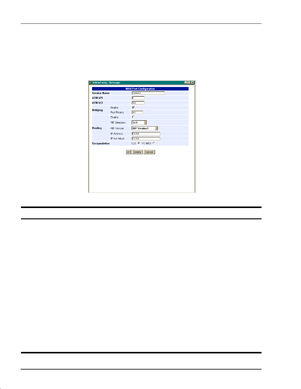
Configuring the WAN Bridging/Routing Sessions
Add a Bridging/Routing WAN Session
You add a bridging/routing WAN session in the WAN Port Configuration window. Use the
following reference table and procedure to set up a session.
Information Description
Service Name A unique descriptive identifier of the session that also displays in the connection
ATM VPI Virtual Path Identifier (VPI) identifies the virtual path that transports ATM cells in a
ATM VCI Virtual Channel Idenifier (VCI) identifies a virtual channel for each session (each
Bridging The function of filtering/forwarding frames based on layer 2 headers.
Enable Enables/Disables bridging.
Port Priority The priority of the WAN port.
Routing The function of routing packets based on layer 3 headers.
Enable Enables/Disables routing.
IP Address The IP address of the modem's WAN port.
IP Net Mask The IP Net Mask address of the modem's WAN port.
RIP Direction The direction the RIP routing information flows.
RIP Version The version of the RIP protocol.
66 Megabit Modem 400F, 500L, 600F , and 700F User Manual
field.
virtual Channel. The range of values is 0 to 15.
session is a virtual channel). Can be a number from 32 up to a maximum of 253 (on
VPI 0, VDIs 254 and 255 are reserved), with the first 32 (0 through 31) reserved.
Page 77

Chapter 7: Configuring Bridging/Routing Se ssio ns
1 To add a session, click Add to display the WAN Port Configuration page.
2 Configure the bridging/routing parameters shown and defined in the figure and table
page 65.
3 Click
4 Click
OK to create the session or click cancel to cancel the set up of the session.
Refresh to update the connections window.
Megabit Modem 40 0F , 50 0L, 600F , and 700F User Manual 67
Page 78

Configuring the WAN Bridging/Routing Sessions
Modify a Bridging/Routing WAN Session
1 Click Edit next to any Port 1-32 to display the Bridging/Router WAN Configuration page for that
port.
2 Change parameters as needed using the table on page 66 for a description of parameters.
Delete a Bridging/Routing WAN Session
1 From the wan menu, click connections to open the WAN Connections window.
2 Select a port and click
3 Click
4 Click
Delete to remove the selected session from the list.
OK to return to connections window or click Cancel to cancel any changes you made
to the current configuration.
5 Click Refresh to update the WAN Connections window.
68 Megabit Modem 400F, 500L, 600F , and 700F User Manual
edit to open the WAN Port Configuration page.
Page 79

Chapter 7: Configuring Bridging/Routing Se ssio ns
CONFIGURING THE LAN
Devices on your local LAN attach to the modem through its LAN port. Configure parameters
for communicating between the local LAN and the modem.
Configure Modem Parameters
Access the General System page to set up modem system
lan
parameters.
1 From the lan menu, click general to open the LAN General
general
window.
Information Description
IP Internet Protocol. Operates at layer 3 and provides addressing.
IP Address The IP address of the modem Ethernet 10/100BASE-T LAN port.
IP Net Mask The IP Net Mask address of the modem Ethernet 10/100BASE-T LAN port.
Bridging The function of filtering/forwarding frames based on layer 2 headers.
Enable Enables/Disables bridging.
Port Priority The priority of the port on a LAN segment.
Routing The function of routing packets based on layer 3 headers.
Enable Enables/Disables routing.
RIP Direction The direction the RIP routing information flows.
RIP Version The version of the RIP protocol.
Megabit Modem 40 0F , 50 0L, 600F , and 700F User Manual 69
Page 80

Configuring the LAN
Information Description
DHCP Dynamic Host Configuration Protocol. Used to assign dynamic IP addresses.
Enable Enables/Disables the modem's DHCP server.
Lease IP Address Range Range of IP addresses to lease out. The starting address is one address higher
Primary DNS IP address of the primary Domain Name Service (DNS) device that translates
Secondary DNS IP address of the secondary Domain Name Service (DNS) device that translates
Default Gateway Default router set to the IP address of the LAN port.
than the LAN IP address. The pool size is 256.
names into IP addresses.
names into IP addresses.
2 Enter the IP address and the Net Mask.
3 Click on the box adjacent to the letters DHCP. A check mark in the box indicates the
modem's DHCP server is enabled. No check mark in th e box indicates the mo dem's DHCP
server is not enabled.
4 Click
Apply.
Saving the Configuration
Although you have submitted your new system settings, the parameters are not permanent
until you write them to NVRAM. See “Saving the Configuration” on page 28 when you want
to save to NVRAM.
70 Megabit Modem 400F, 500L, 600F , and 700F User Manual
Page 81

Chapter 7: Configuring Bridging/Routing Se ssio ns
ACTIVATING AND DEACTIVATING SESSIONS
Activate sessions as you want to use them. Also, you may want to de-activate some sessions,
while leaving other sessions active. Follow one of the two methods below to activate and
deactivate sessions.
From the WAN Connections window:
1 From the
connections to open the
wan menu, click
WAN Connections
window.
2 Select the sessions you
want active then click
Connect. The modem sets
up the session with the
service provider.
3 When dynamically
acquiring an IP address
from the service provider,
the session receives the
IP address at this time.
From the Brouter WAN Port Configuration windo w:
1 From the
wan menu, click connections to
open the WAN Connections window.
2 Click Edit on the box adjacent to the session
to activate or deactivate.
3 To activate the session, place a checkmark
Session Enable box by clicking in it.
in the
To deactivate the session, clear the
checkmark.
4 Click
Megabit Modem 40 0F , 50 0L, 600F , and 700F User Manual 71
OK to accept the changes.
Page 82

Activating and Deactivat i ng Sessions
72 Megabit Modem 400F, 500L, 600F , and 700F User Manual
Page 83

VIEWING STATISTICS
You can view status for the ADSL link (“Viewing ADSL Status”) and for WAN and LAN
statistics (“Viewing Network Statistics” on page 75).
VIEWING ADSL STATUS
The Megabit Modem 400F, 500L, 600F, and 700F displays the status of the ADSL link.
8
Resetting ADSL will close off the ADSL loop connection between the modem
and the service provider. Active connections will disconnect.
Megabit Modem 400F, 500L, 600F , and 700F User Manual 73
Page 84

Viewing ADSL Status
Reference the following table for a description of the System Status parameters.
Information Description
ADSL Link Status Shows the status of the ADSL connection between the modem and the service
Alarms Identifies conditions on the ADSL link that are reported as an alarm such as: Loss of
Current SNR Margin Shows the Signal-to-Noise Ratio (SNR) margin (signal clarity), in decibels, at which
Min SNR Margin Indicates the minimum SNR margin allowed before the ADSL MAR LED on the
Errored Seconds Shows the total number of seconds that ADSL link errors occurred during a 24-hour
Unavailable Seconds Shows the total number of seconds the ADSL link was not available for transmission
Line Attenuation Shows the loss of signal power in the transmission in decibels.
Data Rate Shows the rate of data transmission in kilobits per second (kbps).
1 From the
provider.
Sync (LOS), Loss of Frame (LOF), Loss of Margin (LOM), or Loss of Cell Delineation
(LCD).
the modem is currently operating.
modem front panel lights.
period or since the ADSL link was reset.
since either the modem was powered on or the ADSL statistics were last cleared.
adsl menu, click status to open the ADSL Status windo w.
2 Monitor the ADSL Status.
3 Click
Refresh to update the statistics or Clear to clear the statistics.
74 Megabit Modem 400F, 500L, 600F, and 700F User Manual
Page 85

Chapter 8: Viewing Statistics
VIEWING NETWORK STATISTICS
The Megabit Modem 400F, 500L, 600F, and 700F displ ay statu s for the LAN and WAN link s.
From the
LAN Statistics
The Megabit Modem 400F, 500L, 600F, and 700F displays status for the LAN.
Main Menu, select Statistics to display the Statistics Menu.
View the following LAN information:
Information Description
Rx Packets The total number of packets received at the LAN interface.
Tx Packets The total number of packets transmitted out the LAN interface.
Dropped Packets The total number of packets discarded by the modem.
Collisions The total number of packets that have collided on the LAN segment.
1 From the
statistics menu, click LAN to open the LAN Statistics window.
2 Monitor the LAN statistics.
3 Click
Megabit Modem 400F, 500L, 600F , and 700F User Manual 75
Refresh to update the statistics or Clear to clear the statistics.
Page 86

Viewing Network Statistic s
WAN Statistics
The Megabit Modem 400F, 500L, 600F, and 700F displays status for the WAN.
View the following WAN information:
Information Description
Rx Packets The total number of packets received at the WAN interface.
Tx Packets The total number of packets transmitted out the WAN interface.
Bad Packets The total number of errored packets detected at the WAN interface.
1 From the
statistics menu, click WAN to open the WAN Statistics window.
2 Monitor the WAN statistics.
3 Click
76 Megabit Modem 400F, 500L, 600F, and 700F User Manual
Refresh to update the statistics or Clear to clear the statistics.
Page 87

MAINTENANCE AND
TROUBLESHOOTING
MAINTENANCE
You can update software by specifying a device on your LAN where you will place new
software for the update (see “Defining TFTP Parameters ” on page 36). Then, use the procedure
“Updating Software ” on page 77 to download new software from the TFTP device to the
Megabit Modem 400F, 500L, 600F, and 700F.
Through the RS-232 MGMT port on the Megabit Modem 600F and 700F, you can change the
modem LAN port IP address and network mask, the default gateway IP address, and the IP
address for the device on the LAN that can administer the modem (see page 80).
Updating Software
Updating software images in binary format req uire th e use of a TFTP s erver. The TFTP server
stores the files which will be downloaded to your modem. This guide assumes that you have
correctly set up your TFTP server on the same subnet as the modem and that the appropriate
files are available to download.
When updating software remotely, file corruption is a major concern. For example, if an image
file altered during the TFTP process the modem may not restore its connections after a system
reset. To eliminate such possibilities, the modem software performs a CRC check for the
integrity of each file after it has been downloaded.
9
Megabit Modem 400F, 500L, 600F , and 700F User Manual 77
Page 88

Maintenance
Access the General System page to configure the TFTP parameters.
Reference the following table for a description of the TFTP parameters.
Information Description
IP Address The four octet address of the TFTP server (example: 192.168.0.3).
Net Mask The subnet mask of the TFTP server (example: 255.255.255.0).
File Path The path on the TFTP server where the updated software is located. This may or may
File Name The full name of the updated software (example: tiger.bin).
1 From the
2 Enter the
3 Enter the
4 Enter the
5 Enter the
78 Megabit Modem 400F, 500L, 600F, and 700F User Manual
not be required depending on the TFTP server configuration. (Example:
c:\download\)
system menu, click general to open the General System window.
TFTP Server IP address.
TFTP Server Net Mask (subnet mask) for the TFTP server.
File Path where the updated software resides on the TFTP server (if necessary).
File Name of the updated software file.
Page 89

6 Click Apply to activate the changes.
Before initiating a software upgrade, ensure that all files are in the directory
you specified on the TFTP server when you configured system parameters.
Chapter 9: Maintenance and Troubleshooting
7 Click
8 Click
upgrade software to begin the file transfer.
Proceed to confirm the file transfer process.
9 Wait for the file to download.
10 Click
Yes to restart the modem.
Megabit Modem 400F, 500L, 600F , and 700F User Manual 79
Page 90

Maintenance
Using the RS-232 Management Port
Use the RS-232 management port only when you must manually change the IP address and
subnet mask. Also, use the port if you do not remember the administrative IP address you
entered on your modem.
The Megabit Modem 400F and 500L do not have an RS-232 port.
1 Connect the modem to a PC as shown below.
PC, hub or other
network device
Wall jack with DMT ADSL
service
Switch
MDI MDI-X
10/100BASE-T port
10BASE-T
RS232
M
GMT
RS-232 MGMT port
(600F and 700F only)
ADSL port
Power
connector
D
S
L
P
O
W
E
R
80 Megabit Modem 400F, 500L, 600F, and 700F User Manual
Page 91

Chapter 9: Maintenance and Troubleshooting
2 Configure these communication settings (if using terminal emulation, select AN SI ):
• 9600 baud
• no parity
• 8 data bits
• stop bit
• flow control off
3 Display the following screen:
Pairgain Megabit Modem 700F Setup Menu
===========================================
BSP version: 3.0.0(1)
SW version: 3.2.0
IP address: 192.168.0.1
IP network mask: 255.255.255.0
Default gateway IP address: 0.0.0.0
Admin IP address: 0.0.0.0
===========================================
(1)Enter IP address
(2)Enter IP network mask
(3)Enter default gateway IP address
(4)Enter IP Admin address
(5)Reset modem
(6)Change password
(7)Logout
>
Megabit Modem 400F, 500L, 600F , and 700F User Manual 81
Page 92

Maintenance
4 Enter any of these parameters at the prompt:
• Type then enter the LAN IP address for the modem (LAN port which is the
1
10/100BASE port).
• Type then enter the LAN IP network mask for the modem.
• Type then enter the Default gateway IP address.
• Type then enter the IP address for a device on the LAN that will manage the modem.
5 Type to reset the modem after you change the LAN IP address and the LAN IP
2
3
4
5
network mask.
82 Megabit Modem 400F, 500L, 600F, and 700F User Manual
Page 93

Chapter 9: Maintenance and Troubleshooting
SETTING UP THE PC TO REQUEST AN IP ADDRESS
The modem, as a Dynamic Host Configuration Protocol (DHCP) server, pr ovides an IP address
dynamically to devices on the LAN. When you choose to use DHCP for the modem to serve
IP addresses to the devices on your LAN, ensure that the TCP/IP properties are set to
automatically obtain the IP address from the modem.
®
The following is an example of how to set up the PC using Microsoft
use an operating system other than Windows 98, refer to the appro priate operating syst em user
documentation.
Windows® 98. If you
1 Open the
2 Double-click the
Control Panel window by clicking Start, Settings, Control Panel.
Network icon.
3 From the Configuration tab, double-click
4 Select
5 Click
6 Click
7 Click
Obtain an IP address automatically.
OK to close the TCP/IP Properties window.
OK to close the Network window.
OK to restart the computer.
TCP/IP.
Megabit Modem 400F, 500L, 600F , and 700F User Manual 83
Page 94

Troubleshooting
TROUBLESHOOTING
If this occurs: Try this:
PC or hub not
communicating
with the modem
SYNC ADSL LED Contact the service provider when the LED remains off indicating that the modem is not
MARGIN ADSL
LED lights green
LAN TX and RX
LEDs are not on
ADSL TX and RX
LEDs are not on
• Check the LINK LED. If it is off, check the cabling to the 10/100BASE port and to the hub
or the NIC card in the PC to ensure it is secure.
• Check the position of the MDI/MDI-X switch. Set the switch to MDI when connecting to
a PC. Set the switch to MDI-X when connecting to a hub or router.
• Check that you are using a Web browser (Netscape or Internet Explorer) Version 4.0
or newer.
• Check that you have a TCP/IP protocol stack installed on your PC.
• If this is the initial installation, check that you set the IP address on your PC to obtain an
IP address automatically. Make sure you have configured the LAN IP address of the
modem to an address that is on the correct subnet. See “Setting Up the PC To Configure
the Modem” on page 18.
• You configured the LAN IP address of the modem to an address that is not on the
same subnet.
• Check the NIC card installation for correct IRQ, drivers, and adapter setup. See
appropriate documentation for the NIC card.
If none of the above corrects your problem, contact your service provider.
detecting a transceiver at the far end. Flashing green indicates that the modem is attempting
to bring up the link. Solid green indicates that the loop is up.
The modem synchronizes at a minimum transmission rate of 64 kbps. The modem rate
adapts in increments of 32 kbps.
Contact the service provider when the LED is off indicating that the margin is below that
specified by the service provider.
Check that the LINK LED is on. If it is on, you are simply not transmitting or receiving data
on the LAN 10/100BASE-T port. If the LINK LED is not on, check the section “PC or hub not
communicating with the modem” in this table.
Check that the SYNC LED is on. If it is on, you are simply not transmitting or receiving data
on the WAN ADSL port. If, the SYNC LED is not on, contact your service provider.
84 Megabit Modem 400F, 500L, 600F, and 700F User Manual
Page 95

TECHNICAL REFERENCE
This chapter provides technical information about how your modem transmits data between
users on your LAN and a service provider over the WAN.
10
TRANSMISSION ON THE WIDE AREA NETWORK
ATM over DMT ADSL is the technology that provides the high-speed transmission between
the modem and the service provider. This transmission o ccurs over a single-pair telephone line.
The following sections describe these technologies.
ADSL
Asymmetric Digital Subscriber Line (ADSL) is the technology used to transmit dat a between
the modem and service provider at the physical layer. It provides data at asymmetric rates so
that downstream traffic from a service provider to you is faster than upstream traffic from you
to the service provider. The downstream transmission rate is up to 7.552 Mbps, while the
upstream rate is up to 928 Kbps. Included in the ADSL bandwidth is analog POTS.
Discrete Multitone (DMT) is the line coding used for ADSL. Basically, it divides the
bandwidth into subchannels. Some of the subchannels are reserved for analog POTS. The
other subchannels are allocated to upstream and downstream traffic. Within the upstream
and downstream subchannels, some subchannels are used for management and
performance functions.
DMT ADSL provides rate-adaptive transmission that allows the service provider to deliver you
the best transmission rate determined by distance and line conditions.
Megabit Modem 400F, 500L, 600F , and 700F User Manual 85
Page 96

Transmission on the Wide Area Network
ATM
Asynchronous Transfer Mode (ATM) is a technology that can simultaneously transmit voice,
data, and video over ADSL. ATM uses fixed-size cells that transmit over a preestablished
connection called a Permanent Virtual Circuit (PVC). Quality of Ser vice pr ovides UBR.
ATM cells are 53 bytes that comprise a 5-byte header and 48-byte payload. The header includes
the Virtual Path Identifier (VPI) and Virtual Channel Identifier (VCI) that you entered when you
configured each session. The VPI and VCI provide the vir tual conn ection b etween the mod em
and the service provider. The VPI identifies the Virtual Path (VP) that transports ATM cells in
a Virtual Channel (VC). The Megabit Modem 400F, 500L, 600F, and 700F has 32 VCs in the
VP, which provides the 32 sessions.
Mapping an ATM Session
Your service provider will give you a VCI and VPI address for each session. The VCI address
for each session (each session is a VC) can be a number from 32 up to a maximum of 255, with
the first 32 numbers (0 through 31) reserved. The VCI value for each VC must be unique for
each of the 32 sessions. The VPI value must always be 0.
86 Megabit Modem 400F, 500L, 600F, and 700F User Manual
Page 97

Chapter 10: Technical Reference
SYSTEM MODE ENCAPSULATION
Point-to-Point Prot ocol (PPP) ov er ATM or RFC 1483 Br idging /Rout ing are the t wo prot ocol s
you can use to encapsulate data for transport across the ADSL WAN. The following sections
describe these protocols.
PPP
PPP runs over ATM virtual circuits. PPP exists between the hardware layer and the
network-layer interface protocols. It is a widely used protocol for establishing connections on
the WAN. PPP provides the set up and release of connections for each session. PAP/CHAP
provide the authentication for the PPP sessions.
In PPP over ATM mode, you can map private IP address LAN users to PPP sessions using RFC
1631 Networ k Address Translation protocol.
PAP/CHAP Authentication Security
Password Authentication Protocol (PAP) and Challenge-Handshake Authentication Protocol
(CHAP) are two ways to authenticate PPP sessions. PAP and CHAP are both offered since some
systems support only PAP. With PAP, the modem sends authentication reques ts to the service
provider and authentication occurs only once during the life of the link.
With CHAP, the service provider returns an authentication challenge to the modem during
authentication. CHAP can be renegotiated during the life of the link. Also, bo th the modem and
the service provider must support clear text versions of the password. The CHAP host field must
be the same on both ends of the session.
NAT
RFC 3022 Network Address Translation (NAT) includes two operations. They are Basi c NAT
and Network Address Port Translation (NAPT).
Basic NAT only deals with IP addresses. Therefore, it is a one-to-one private IP address to
public IP address (proxy address) mapping. Basic NAT allows you to hide your private
addresses behind the public IP addresses assigned to a session. Corporations that need flexibility
using different IP address ranges can benefit from this operation, as the private IP addresses will
remain the same when the public IP addresses are reassigned.
Megabit Modem 400F, 500L, 600F , and 700F User Manual 87
Page 98

System Mode Encapsulation
NAPT does not have the limitation of using only the IP address in the translation. It also uses
TCP/UDP ports. It is a method that allows multiple IP addresses and their TCP/UDP ports to be
translated into one IP address and its ports. A good candidate for NAPT is a small office with
multiple hosts but one public IP address. In this case, NAPT allows the entire office to use the
public IP address to communicate out of the private network.
An example of NAPT in this small office envionment is the RealPlayer™ application. The
RealPlayer (client at the office) initiates a TCP connection to the RealServer™ on the Internet,
which then initiates a UDP connection back to RealPlayer. RealPlayer can then tell the server
to use a specific UDP port for the UDP connection. The user should set up a static NAT entry
for the UDP connection for RealPlayer to work properly through NAPT.
Bridging
You can configure the Megabit Modem 400F and 700F as a bridge to forward Ethernet data
based on MA C addresses.
MAC Layer Bridging
A bridge moves information across a network from a source to a destination at the data link layer
(of an OSI reference model). The information is sent to a physical address known as a Media
Access Control (MAC) address. The Megabit Modem 400F and 700F provide transparent
Ethernet MAC-layer bri dging.
The bridge learns up to 1 024 ad dresses. Additio nally, when you configur e the mo dem, y ou can
add 32 static addresses through the static MAC address configuration page.
Spanning Tree Protocol
The Megabit Modem 400F and 700F support 80 2.1d Sp annin g Tree protocol which elimi nates
loops in a LAN topology by partitioning out redundant links between LAN seg ments. This
ensures that there is only one path, or link, between any two nodes on the network. If this link
goes down, Spanning Tree re-enables partitioned links to create a new loop-free topology if
possible.
An example of the active topology is shown on page 89. In the example, the spanning tree
algorithm partitions out the bridge from LAN A to LAN B, and creates the link from ENET2
to Bridge 5.
88 Megabit Modem 400F, 500L, 600F, and 700F User Manual
Page 99

Chapter 10: Technical Reference
Example LAN Physical Network
This physical configuration is valid only when used with
Spanning Tree to eliminate loops.
LAN
Bridge 3Bridge 2Bridge 1
ENET 1
LAN
Bridge 4
E
N
E
T
2
Bridge 5
ENET 3
Loop-freeT opology
Using SpanningTreeProtoc o l
LAN A
Bridge 3Bridge 2Bridge 1
ENET 1
LA BN
Bridge 4
Megabit Modem 400F, 500L, 600F , and 700F User Manual 89
E
N
E
T
2
Bridge 5
ENET 3
Page 100

System Mode Encapsulation
Routing
You can configure the Megabit Modem 400F and 700F router to route Ethernet-encapsulated
IP datagrams based on IP addresses. Use Routing Information Protocol (RIP) to automatically
identify the route from the session on the Megabit Modem 400F and 700F to the destinatio n.
You can specify the direction and version of RIP that allows other routers to update their routing
tables automatically (for example, information on how many hops between destinations). The
version of RIP you select for the session must match the version supported by the service
provider. Versions RIP1 and RIP-1 compatible are used for broadcast. RIP Version 2 is used
for multicast.
The router also learns addresses. In addition to the addresses it learns, you can add 32 static
route entries on the LAN Brouter con figuration page. Through the s tatic IP routing featu re, you
can configure the Megabit Modem 400F and 700F as an IP router with statically programmed
route entries. You can enable this function to provide broadcast filtering and to prevent
eavesdropping by specifying multiple destination gateways. When static IP routing is enabled,
you can access only specific remote IP subnets or hosts.
Since IP routers make forward or filter decisions bas ed on the network-layer IP address instead
of the MAC hardware address, MAC-level broadcast frames are prevented from reaching
unwanted destinations in the network.
When setting parameters for an external router, configure a Static Route entry in any of the
external routers that may have been specified as a Default Router or as a Gateway. This
implementation prevents other parties from discovering routes through eavesdropping. The
format of this entry varies among the various router vendors, but is typically in the form of
"Destination," "Mask," and "Gateway," where the "Destination" is the remote IP Subnet or host
address, and "Gateway" is the IP address of the modem on the same subnet as the external
router.
Encapsulation for RFC 1483 Bridging/Routing
Most users select LLC, which allows you to run multiple protocols over the VC. An
encapsulation header identifies the types of protocol being carried in the transmission (for
example, IP). VC-MUX allows only one proto col to run over th e VC. The type of protocol must
be negotiated between the modem and the service provider prior to the transmission. Because
there is only one protocol allowed, the header is not required.
90 Megabit Modem 400F, 500L, 600F, and 700F User Manual
 Loading...