

Page 1
AlphaPremiere™ 9000 Series Sign
Installation Instructions
(Go to http://www.adaptivedisplays.com/support/premiere for the latest information.)
Contents
Introduction . . . . . . . . . . . . . . 1
Messaging software options . . . . . . .1
Related documentation. . . . . . . . . . . . 1
Controls and indicators. . . . . . . 2
Technical specifications . . . . . . 4
Sign specifications. . . . . . . . . . . . . . . 4
Temperature protection . . . . . . . . . . . 4
EMI compliance . . . . . . . . . . . . . . . . . 4
Safety information . . . . . . . . . . 5
General . . . . . . . . . . . . . . . . . . . . . . .5
Internal battery replacement . . . . . . . . 5
Sign configuration . . . . . . . . . . 6
Setting DIP switches . . . . . . . . . . . . . 6
Speaker volume control . . . . . . . . . . .9
Using the IR remote control . . . . . . .11
Setting time . . . . . . . . . . . . . . .12
Setting date. . . . . . . . . . . . . . . . 12
Clearing memory . . . . . . . . . . . 12
Test menu. . . . . . . . . . . . . . . . . 13
Setting sound volume. . . . . . . .13
Networking . . . . . . . . . . . . . . .14
RS232 . . . . . . . . . . . . . . . . . . . . . . .14
RS485 . . . . . . . . . . . . . . . . . . . . . . .15
Ethernet . . . . . . . . . . . . . . . . . . . . . . 16
Installation . . . . . . . . . . . . . . .20
Environmental requirements . . . . . .20
Reducing electrical noise . . . . . . . . . 20
Checking speaker volume . . . . . . . . 20
Wall mounting instructions . . . . . . .20
Ceiling mounting instructions . . . . . . 22
Counter mounting instructions. . . . . . 23
Checkout procedure . . . . . . . . . . . . . . 24
Service and maintenance . . . . .24
Firmware updates. . . . . . . . . . . . . . . 24
Routine cleaning . . . . . . . . . . . . . . . 24
Introduction
AlphaPremiere™ 9000 series signs are indoor, four-line, full matrix
LED displays. These signs can display both text and graphics and can be
networked together. Two speakers are built into the sign’s right end cap.
External status LEDs monitor all communication data and provide
self-diagnostic capability.
Messaging software options
To display text and graphics on an AlphaPremiere™ sign, some type
of messaging software is required to create and to send messages. The
following options are available:
• AlphaNET plus™ for Windows® software
• Alpha® Messaging software
•Smart Alec® software
• Alpha® ActiveX® Marquee Control software
• Custom messaging software created using the Alpha® sign
communications protocol
Related documentation
Most of the following documents are available at the Adaptive® web
site:
Document name Part number Description
AlphaNET plus™ for Windows® User
Manual
Messaging Software User Manual 9701-0202 Basic sign messaging with a PC.
Smart Alec® User Manual 9709-2030 Intelligent messaging software with OPC Client
ActiveX® Developer’s Reference 9709-2054
Alpha® Sign Communications Protocol 9708-8061 Used to create custom messaging solutions.
Network Configurations 9708-8046 Basic reference for networking Adaptive® signs .
9708-8081
Allows the creation and scheduling of messages
for display on signs.
Explains how to use the Alpha® ActiveX®
Marquee Control software.
The following are trademarks of Adaptive Micro Systems: Adaptive, Alpha, AlphaNet plus, AlphaEclipse, AlphaPremiere, AlphaTicker, AlphaVision, AlphaVision InfoTracker, Automode,
Revision date: 10/25/2001 9711-4201C
Adaptive Micro Systems • 7840 North 86th Street • Milwaukee, WI 53224 USA • 414-357-2020 • 414-357-2029 (fax) • http://www.adaptivedisplays.com
BetaBrite, BetaBrite Director, BetaBrite Messaging Software, Big Dot, PPD, Smart Alec, Solar, TimeNet
The distinctive trade dress of this product is a trademark claimed by Adaptive Micro Systems, Inc.
Due to continuing product innovation, specifications in this manual are subject to change without notice.
© Copyright 2001 Adaptive Micro Systems, Inc. All rights reserved.
1
Page 2
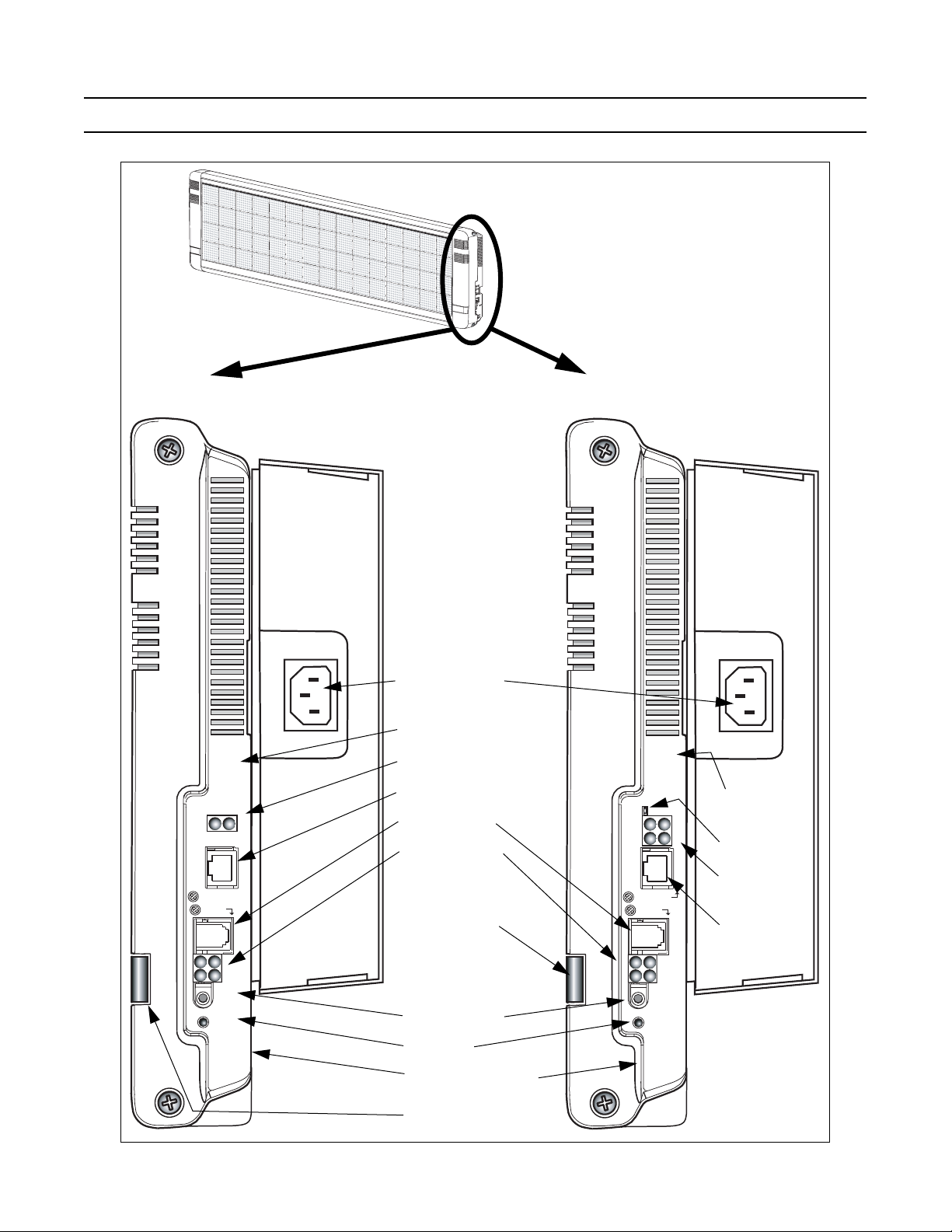
Controls and indicators
There are two available configurations for communication.
232/AUX
RXD
TXD
6
232/AUX
RS
5
8
4
S
R
4
2
kr
p
S
t
u
O
n
ig
S
t
se
e
R
5
RS48
Standard
Configuration
RS232/Aux
5. RXD
6. TXD
5
Optional Ethernet
Configuration
Power supply plug
A
RS232 status LEDs label
B
RS232 status LEDs
C
RS232 RJ11 jack
D
6
RS485 RJ11 jack
E
RS485 status LED
F
10 Base T
5.
FAULT
6.
RXD/TXD
7.
ACTIVITY
8. LINK
56
78
Ethernet status
K
LEDs label
Ethernet reset
L
Ethernet status
M
RS232/Aux
RS485
IR remote sensor
G
10 Base T
RS485
LEDs
N
Ethernet RJ45
jack
34
12
Spkr
Out
Sign
Reset
RS485
1.Pwr/Micro
2.RXD
3.FlashProg
4.TXD
H
Speaker out jack
Sign reset
I
J
RS485 status LEDs label
IR remote sensor
G
34
12
Spkr
Out
Sign
Reset
RS485
1. Pwr/Micro
2. RXD
3. FlashProg
4. TXD
2
Page 3
3
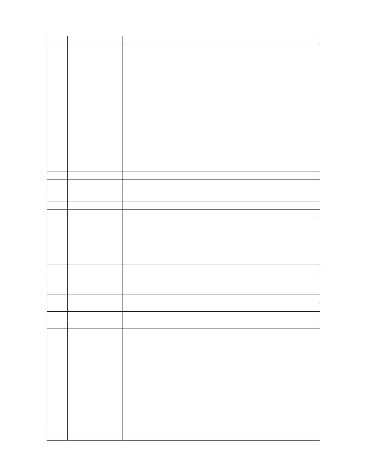
Item Name Description
The plug on the power supply cord serves as the disconnect device for this display. During mounting
and installation of the display, make sure that the electrical power socket/outlet is easily accessible and
that it is located close by the display.
Français
La fiche du cordon d’alimentation sert de dispositif de débranchement pour cet affichage. Lors du
montage et de l’installation de l’affichage, assurez-vous que la prise d’alimentation
facilement accessible et qu’elle se situe près de l’affichage.
Deutsch
Der Stecker am Netzteilkabel fungiert als Trennvorrichtung für dieses Anzeigeschild. Während der
A
Power supply plug
Montage und Installation des Schildes ist sicherzustellen, dass die Netzsteckdose leicht zugänglich ist
und sich nahe am Schild befindet.
Italiano
La spina del cavo di alimentazione serve anche come dispositivo di scollegamento di questo display.
Durante il fissaggio e l’installazione del display, accertarsi che la presa di corrente sia facilmente
raggiungibile e sia situata vicino al display.
Español
La clavija del cable de alimentación sirve como dispositivo de desconexión para este anuncio. Durante
el montaje y la instalación del anuncio, asegúrese de que el receptáculo/tomacorriente el
fácilmente accesible y que est
B
RS232 status LEDs label Information label for RS232 LED status
é
‚ubicado cerca del anuncio.
RS232 communications status LEDs:
C
RS232 status LEDs
• LED 5: TXD (Transmitted Data)
• LED 6: RXD (Received Data)
D
RS232 RJ11 jack RJ11 jack for RS232 data. This is NOT a telephone jack.
E
RS485 RJ11 jack RJ11 jack for RS485 data. This is NOT a telephone jack.
RS485 communication status LEDs:
• LED 1: Pwr/Micro
- Blinking blue LED = ok.
F
RS485 status LEDs
- If blue LED is steady or off, contact Adaptive® Technical Support.
• LED 2: TXD (Transmitted Data)
• LED 3: Flash Prog
• LED 4: RXD (Received Data)
G
IR remote sensor Receiving window for signals from the handheld Infrared Remote Control
Speaker out jack allows connecting to any self-powered external speaker (such as typical PC speakers).
H
Speaker out jack
NOTE: A stereo plug must be used to connect external speakers. Using a mono plug
could damage the sign.
I
Sign reset Momentary switch allows you to cycle through power-up messaging
J
RS485 status LEDs label Information label for RS485 LED status
K
Ethernet status LEDs label Information label for Ethernet LED status
L
Ethernet reset Momentary switch allows you to reset Ethernet hardware
Ethernet communication status LEDs:
• LED 5 (red): FAULT — Blinks or lights red in combination with LED 6 to indicate diagnostics and
error detection:
Red solid and LED 6 blinking:
- 1x = EPROM checksum error
- 2x = RAM error
- 3x = network controller error
M
Ethernet status LEDs
- 4x = EEPROM checksum error
- 5x = duplicated IP address on the network (non-fatal error)
- 6x = software does not match hardware (non-fatal error)
Red blinking and LED 6 blinking:
- 4x = faulty network connection (non-fatal error)
- 5x = no DHCP response received (non-fatal error)
• LED 6 (green): RXD/TXD — Solid green indicates idle. Blinking indicates transmission/reception.
• LED 7 (yellow): ACTIVITY — Solid yellow indicates idle. Blinking indicates a network connection.
• LED 8 (green): LINK — Solid green indicates network port connected to the network.
N
Ethernet RJ45 jack RJ45 jack for Ethernet connection
é
lectrique est
é
ctrico quede
Page 4
Technical specifications
Sign specifications
Sign
model
9080 80 32
9120 120 32
9160 160 32
9200 200 32
9240 240 32
LED
columns
LED
rows
LED color
Tricolor
Dimensions
(L x W x H)
28 x 2.2 x 12 (in)
71.1 x 5.59 x 30.5 (cm)
40 x 2.2 x 12 (in)
101.6 x 5.59 x 30.5 (cm)
52 x 2.2 x 12 (in)
132.1 x 5.59 x 30.5 (cm)
64 x 2.2 x 12 (in)
162.6 x 5.59 x 30.5 (cm)
76 x 2.2 x 12 (in)
193 x 5.59 x 30.5 (cm)
Weight
(approx)
18 (lb)
8.2 (kg)
23 (lb)
10.4 (kg)
31 (lb)
14.1 (kg)
36 (lb)
16.3 (kg)
41 (lb)
18.6 (kg)
Input voltage
(VAC)
100 - 240
@ 50 - 60 Hz
Input current
@ 100 VAC @ 240 VAC
2.0 amps 1.0 amps
3.0 amps 1.5 amps
3.6 amps 1.8 amps
4.0 amps 2.0 amps
5.0 amps 2.5 amps
Temperature protection
The AlphaPremiere™ 9000 sign includes automatic temperature controls to determine when the internal
temperature of the sign is too hot to continue normal operation. While the temperature controls are based
primarily on the internal temperature of the sign, they are also affected by both ambient temperature and the
sign’s load and its duration. So the higher the ambient temperature and the more LEDs that are on and the longer
they are on, the higher the internal temperature.
Trigger temperature levels may vary from sign to sign, but in general the functioning is:
• As the temperature of the sign rises, cooling fans are switched on. If the temperature falls below the
cooling fan threshold level, the cooling fans are turned off.
• If, however, the temperature of the sign continues to rise, auto-dimming occurs. This means that the
LED output from the sign is forced into a reduced power mode, effectively dimming the brightness of
the LEDs. If the temperature falls below the auto-dimming threshold level, then auto-dimming stops
and the LED brightness returns to normal level.
EMI compliance
This equipment has been tested and found to comply with the limits for a Class A digital device, pursuant
to Part 15 of the FCC Rules. These limits are designed to provide reasonable protection against harmful
interference when the equipment is operated in a commercial environment.
This equipment generates, uses, and can radiate radio frequency energy and, if not installed and used in
accordance with installation guidelines, may cause harmful interference to radio communications. Operation of
this equipment in a residential area is likely to cause harmful interference, in which case the user will be required
to correct the interference at his own expense.
WARNING: This is a Class A product. In a domestic environment this product may cause radio interference, in which case the
user may be required to take adequate measures.
4
Page 5
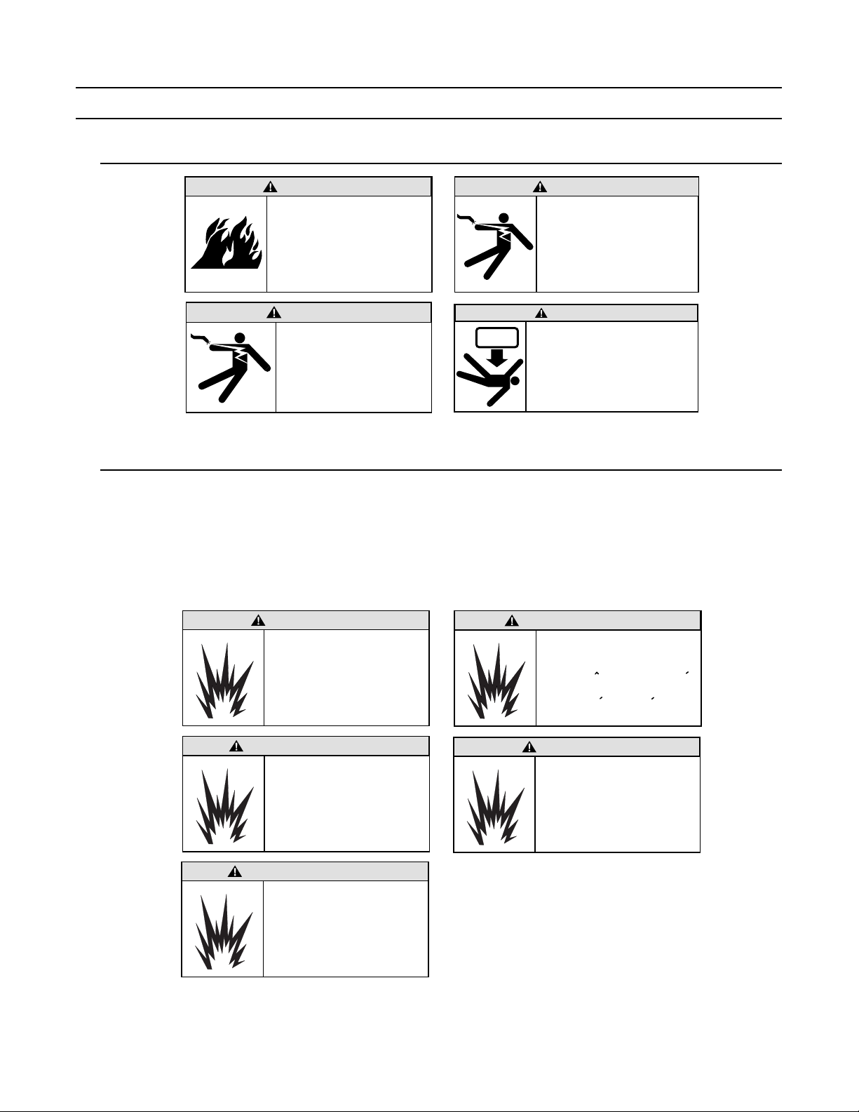
Safety information
General
WARNING
Possible fire hazard.
Always mount unit indoors.
Mounting the unit
outdoors may cause a fire
which could result in serious
injury or death.
WARNING
Hazardous voltage.
Contact with high voltage
may cause death or
serious injury. Always
disconnect power to sign
prior to servicing.
WARNING
Possible shock hazard.
Always mount unit indoors.
Mounting a unit outdoors
makes the unit a possible
source of electric shock
which could result in
serious injury or death.
WARNING
Possible crush hazard.
The wall and the mounting system
must be able to support at least
4 times the unit's weight.
Otherwise the unit may fall,
causing serious injury or death.
Internal battery replacement
The AlphaPremiere™ sign uses an internal battery to store and retain message data when the power
supply to the sign is disconnected. If the battery fails while the sign remains connected to a reliable source of
power, you will not become aware of the battery failure until the power supply is lost or interrupted.
NOTE: Backup batteries are soldered in place and should only be replaced by a qualified technician.
If you suspect that your internal backup battery may have failed, please contact Adaptive® Technical
Support.
WARNING
Danger of explosion if battery is
incorrectly replaced. Replace only
with the same or equivalent type
recommended by the manufacturer.
Dispose of used batteries according
to the manufacturer's instructions.
AVVERTENZA
La sostituzione errata della batteria
può comportare il pericolo di esplosione.
Sostituire unicamente con una batteria
identica o di tipo equivalente consigliata
dal fabbricante. Eliminare le batterie
scariche in base alle istruzioni del
fabbricante.
ADVERTENCIA
Existe el peligro de explosión si la batería
se reemplaza incorrectamente.
Reemplácela sólo con el mismo tipo de
batería o uno equivalente recomendado
por el fabricante. Deseche las baterías
usadas de acuerdo con las instrucciones
del fabricante.
AVERTISSEMENT
Il y a danger d'explosion s'il y a un
remplacement incorrect de la batterie.
Remplacer uniquement avec une
batterie du meme type recommande
par le fabricant. Mettre au rebut les
batteries usagees conformement
aux instructions du fabricant.
WARNUNG
Bei einem nicht vorschriftsgemäßen
Austausch der Batterie besteht
Explosionsgefahr. Nur durch eine Batterie
des gleichen oder eines gleichwertigen,
vom Hersteller empfohlenen Typs
ersetzen. Gebrauchte Batterien gemäß
Herstelleranweisung entsorgen.
5
Page 6
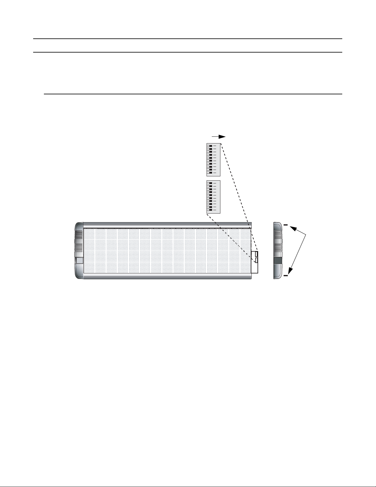
Sign configuration
End cap screws
DIP switch 1
DIP switch 2
ON
Use a small screwdriver to move each DIP switch.
Before installing a sign, you may want to change one or more of the sign’s default settings by changing
settings on DIP switches inside the sign.
To access and change DIP switches, follow these steps:
Setting DIP switches
1. Remove power from the sign.
2. If the sign is mounted, remove it and place the sign on a flat surface before removing the end cap.
3. Remove the two (2) screws from the end cap located on the right side of the sign:
4. See the pages following to make changes in these functions:
• EOL termination
• Baud rate
• RS485 echo
• IR remote disable
• Demonstration messages
•Memory clear
• Serial address
• Data format
12345668910 12345668910
• Diagnostics
5. After making the appropriate DIP switch changes, re-attach the end cap. Tighten the end cap screws to
14 lb-in, 1.58 Nm.
6
Page 7
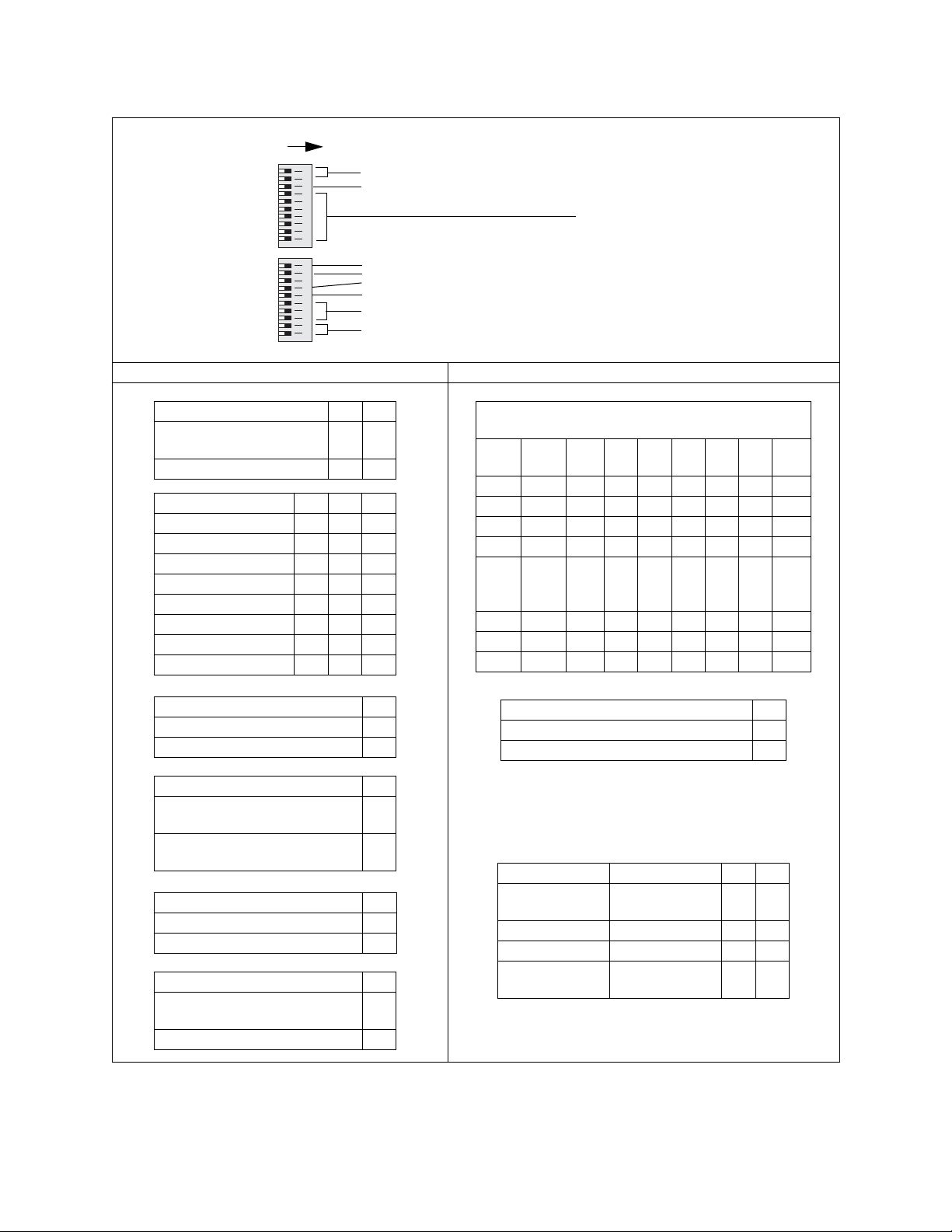
Bank 1 and Bank 2 DIP switches
ON
DIP switch 2
DIP switch 1
12345678910 12345678910
Bank 1 DIP switches Bank 2 DIP switches
Switches 9, 10: Diagnostics
Switch 8: Data format
Switch 10: Memory clear
Switch 9: Demonstration messages
Switch 7: IR Remote disabled
Switch 6: RS485 echo (See page 8.)
Switches 3, 4, 5: Baud rates
Switches 1, 2: EOL termination
Switches 1 through 7:
Serial address in binary format.
Switch 1 = LSB (Least Significant Bit)
Switch 7 = MSB (Most Significant Bit).
EOL termination 1 2
Set end-of-line termination off
(default)
00
Set end-of-line termination on 1 1
Baud rate 3 4 5
9600 (default) 0 0 0
1200 1 0 0
2400 0 1 0
4800 1 1 0
9600 0 0 1
19200 1 0 1
38400 0 1 1
9600 1 1 1
RS485 echo (See page 8.) 6
Disable RS485 echo (default) 0
Enable RS485 echo 1
IR remote disable 7
IR remote control can be used to change
a sign’s parameters (default)
IR remote control can not be used to
change a sign’s parameters
Demonstration messages 9
Enable demo messages (default) 0
Disable demo messages 1
Memory clear 10
Do not clear messages at power-up
(default))
Clear all messages at power-up 1
Serial Address (address 0 = default)
LSB = Least Significant Bit; MSB = Most Significant Bit
1
Dec Hex
23456 7
LSB
MSB
000000000 0
101100000 0
202010000 0
303110000 0
.
.
.
.
.
.
.
.
.
.
.
.
.
.
.
.
.
.
.
.
.
.
.
.
.
.
.
125 7D 1 011111
126 7E 0 11111 1
127 7F 1 11111 1
Data format 8
8N1 = 8 data bits, no parity, 1 stop bit. (default) 0
7E2 = 7 data bits, even parity, 2 stop bits 1
Note: For Ethernet, when you change the Data format using DIP switches,
a similar change must be made to the Data format of the internal Ethernet
0
card. (See “Setting Baud rate and Data format on an Ethernet-equipped
sign” on page 19.)
1
Diagnostic Description 9 10
Run normal
messages (default)
Normal messaging
enabled.
00
Test pattern Test for unlit LEDs. 1 0
LED test mode Test for dim LEDs. 0 1
Serial
troubleshooting
Contact Adaptive®
Technical Support.
11
0
7
Page 8
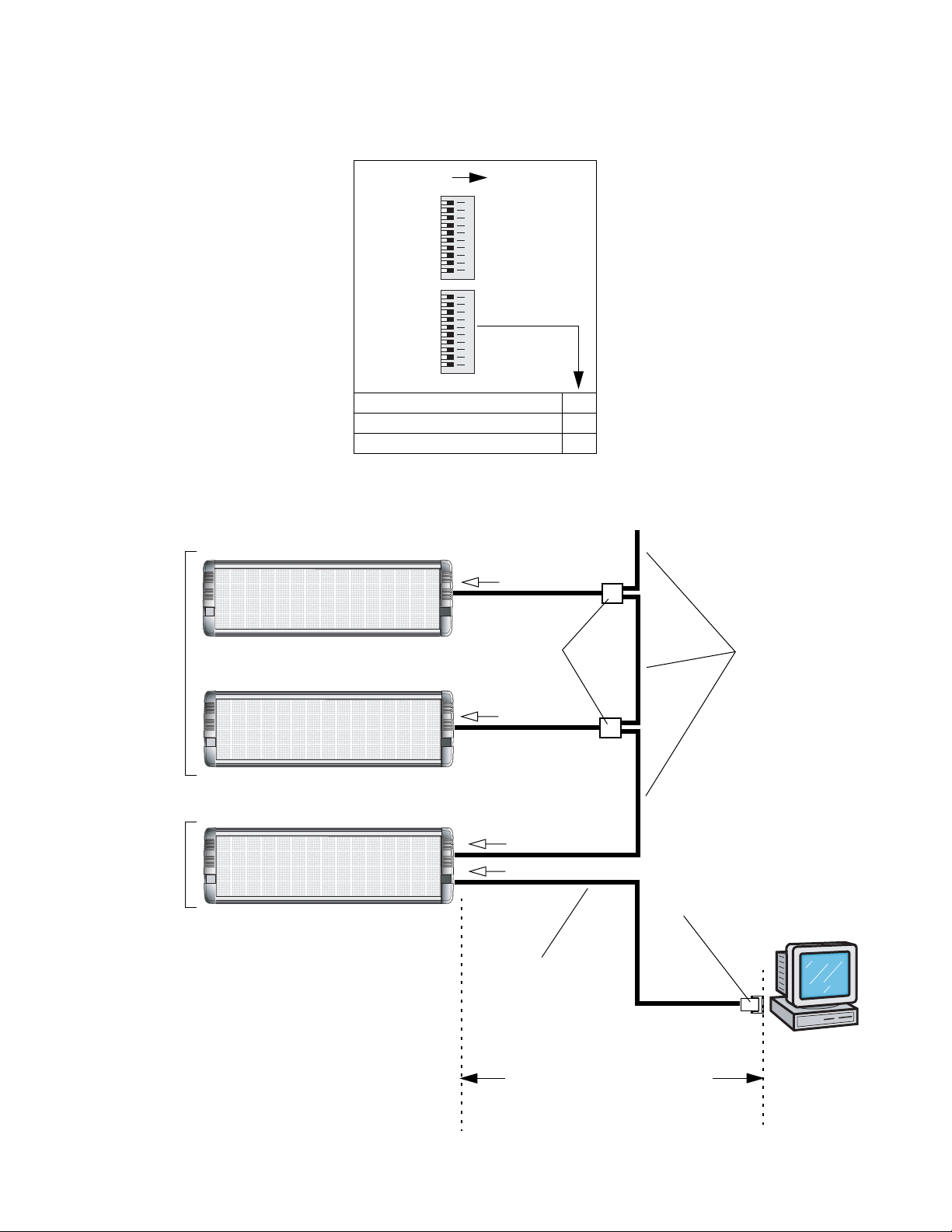
RS485 echo (default = RS485 ECHO DISABLED)
When RS485 echo is enabled, then incoming data (from either RS232 or Ethernet) is echoed or sent out the
RS485 jack:
DIP switch 2
ON
RS485 echo is useful when connecting multiple signs together because it can eliminate the need to use a
Converter Box:
RS485 echo
= DISABLED
for other signs on the
network
DIP switch 1
use switch 6
12345678910 12345678910
RS485 echo 6
RS485 ECHO DISABLED (default) 0
RS485 ECHO ENABLED 1
To RS485 RJ11 jack
Modular Network Adapter
(pn 4331-0602)
To RS485 RJ11 jack
To next sign
RS485 cable
(pn 1088-8000)
RS485 echo
= ENABLED
for this first sign in
the network
8
To RS485 RJ11 jack
To RS232 RJ11 jack
RS232 cable
(pn 1088-8625 for 25-foot cable,
pn 1088-8627 for 50-foot cable)
Maximum 50 feet from PC to sign
(If greater than 50 feet, a Converter Box must
be used. See Network Configurations
manual for details.)
RS232 adapter
(pn 4370-0001C for 25-pin COM port,
pn 1088-9108 for 9-pin COM port)
PC running
messaging software
like AlphaNET plus™
for Windows®
software
Page 9

Speaker volume control
Keep one hand on the end cap
after removing both screws, to
avoid pulling speaker wires.
Decrease Increase
The AlphaPremiere™ 9000 sign has two internally-mounted speakers in the right end cap. Audio volume
can be raised or lowered:
• temporarily by using the IR remote control (the “U” key raises volume, the “D” key lowers it), or
• permanently by changing an internal master volume dial (see below).
NOTE: Also, the duration and number of repetitions of audio tones can be set using AlphaNET plus™
software. Refer to the “Site Manager” section of the AlphaNET plus™ for Windows® User
Manual .
To change the default volume setting, follow these steps:
1. Remove power from the sign.
2. If the sign is mounted, remove it and place the sign face down on a flat surface before removing the
end cap.
3. Remove the two (2) screws from the end cap located on the left side of the face down sign:
4. To change the default factory volume setting, use a screwdriver to turn the dial clockwise to raise the
volume or counterclockwise to lower the volume. (It is recommended that you use a plastic
screwdriver, not a steel screwdriver, to make the adjustment.) The default factory setting is maximum.
NOTE: To turn on a continuous repeated tone for volume adjustment, use the IR remote control to go
through functions as described in “Using the IR remote control” on page 11. When you get to
Volume , you’ll be able to hear the speaker volume increase and decrease as the adjustable dial
is rotated. However, this is a temporary setting only.
9
Page 10
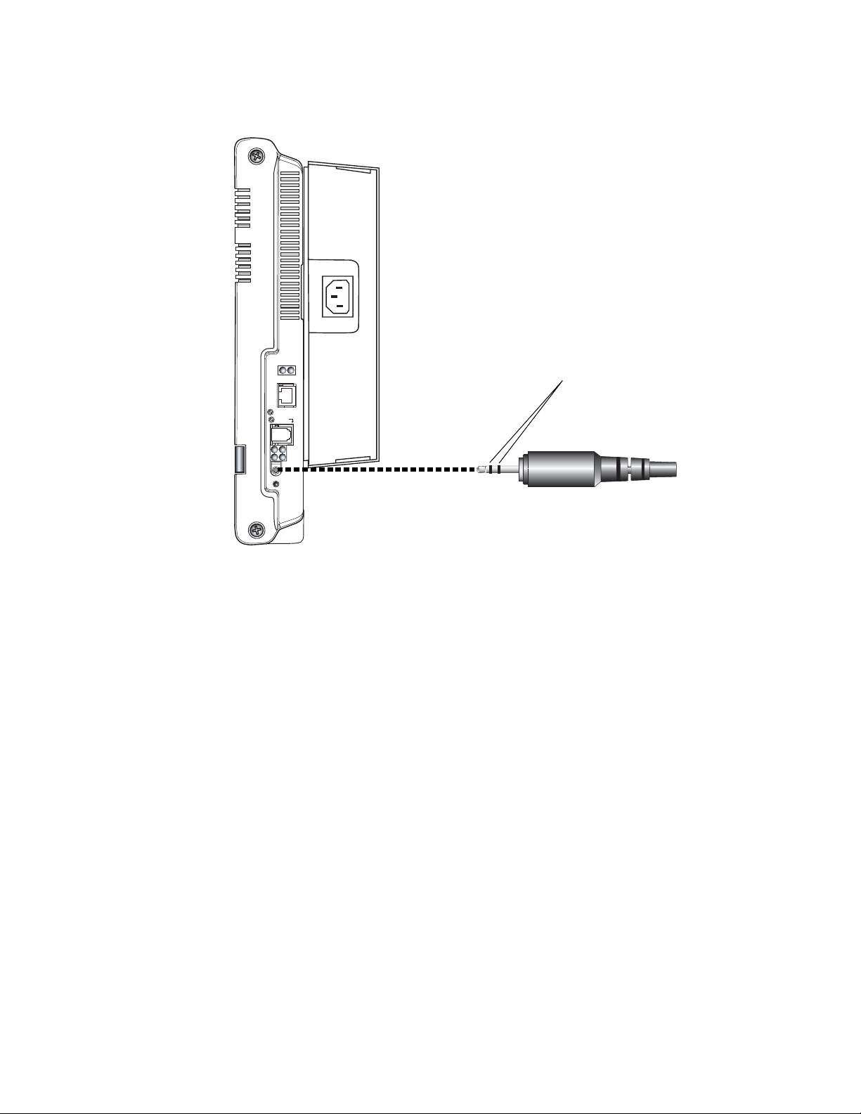
Only use a stereo plug to connect external
speakers. Using a mono plug may damage
the sign. A stereo jack will have two bands.
A mono jack will only have one band.
5. For remote audio connections or to boost volume output, a stereo speaker plug can be connected to
the Speaker out jack. Use DC inline speakers of the type used to improve output from a personal
computer.
RS232/Aux
5. RXD
6. TXD
5
6
RS232/Aux
RS485
34
12
Spkr
Out
Sign
Reset
RS485
1.Pwr/Micro
2.RXD
3.FlashProg
4.TXD
10
Page 11
Using the IR remote control
The IR remote control is used to set up and test an AlphaPremiere™ sign. However, messages cannot be
programmed into an AlphaPremiere™ sign using the remote control.
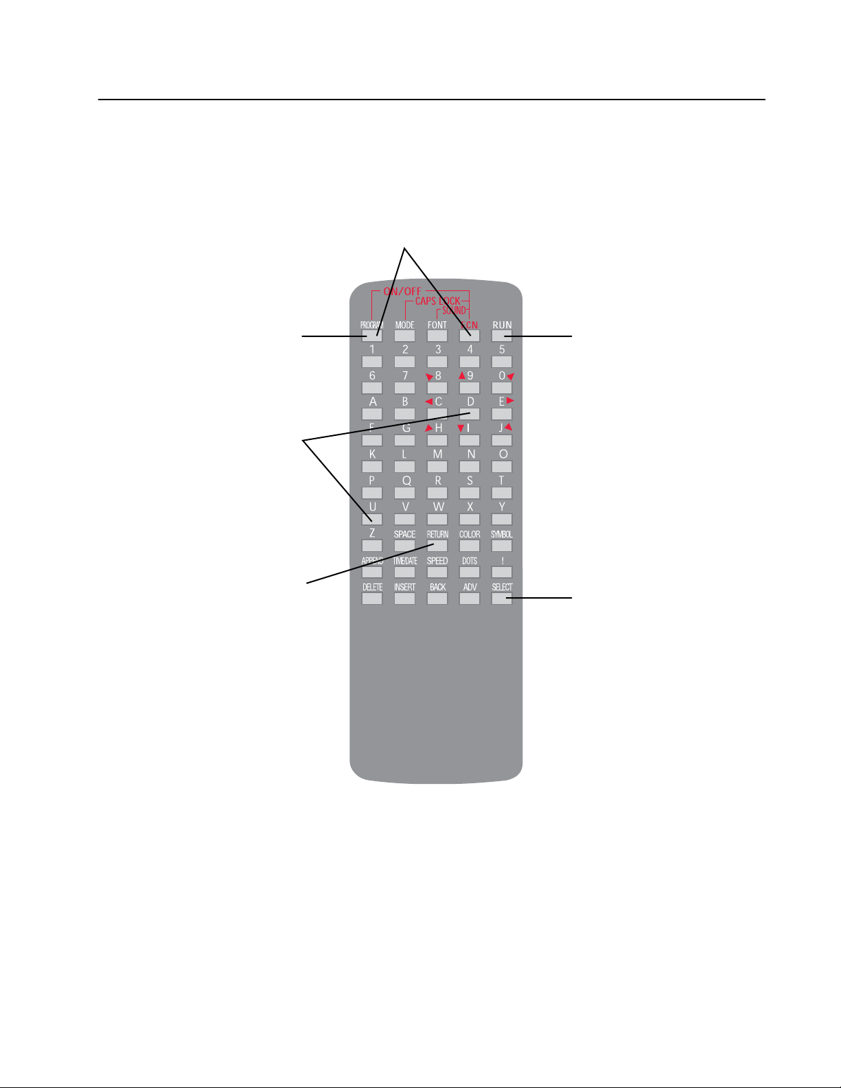
Most of the keys on the IR remote control are not usable with an AlphaPremiere™ sign. The illustration
below shows the remote control keys that can be used:
TURN SIGN ON/OFF
Hold down the FCN key and then
press the PROGRAM key.
PROGRAM
Used to access the sign’s
PROGRAM menu which can be
used to set the time, date, etc.
SOUND VOLUME
Use the U and D keys to raise
or lower the sign’s speaker
volume,. (See page 13.)
RETURN
Used to choose or to set a menu option.
RUN
Press to exit the PROGRAM menu.
SELECT
Used to choose a menu option
11
Page 12
Setting time
Setting date
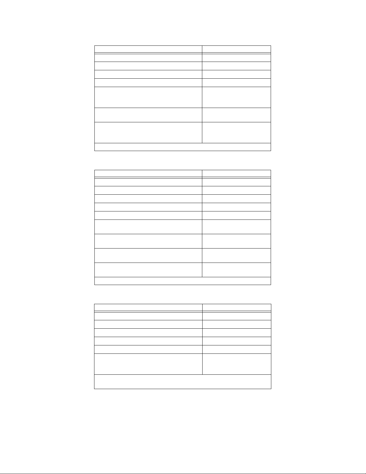
When you press this . . . You’ll see this on the sign . . .
PROGRAM key
SELECT key
SELECT key
SELECT key
RETURN key
Then keep pressing RETURN key until the desired hour
appears.
SELECT key
Press RETURN key until the desired minutes appears.
SELECT key
Press RETURN key to select either a 12-hour or a 24hour time display format.
Then press the RUN key.
When you press this . . . You’ll see this on the sign . . .
PROGRAM key
SELECT key
SELECT key
SELECT key
SELECT key
RETURN key
Press RETURN key until the desired month appears.
SELECT key
Press RETURN key until the desired date appears.
SELECT key
Press RETURN key until the desired year appears.
SELECT key
Press RETURN key until the desired day appears.
Then press the RUN key.
PROGRAM
TURN OFF
RUN DEMO/TIME
SET TIME
HOUR
MIN
12HR or 24HR
PROGRAM
TURN OFF
RUN DEMO/TIME
SET TIME
SET DATE
MONTH
DATE
YEAR
WEEKDAY
Clearing memory
When you press this . . . You’ll see this on the sign . . .
PROGRAM key
SELECT key
SELECT key
SELECT key
SELECT key
SELECT key
Press RETURN to clear all the messages from the sign’s
memory.
The sign will display the information in “Checkout procedure” on page 24.
Then the sign will go blank.
12
PROGRAM
TURN OFF
RUN DEMO/TIME
SET TIME
SET DATE
CLEAR MEMORY
Page 13
Test menu
PROGRAM key
SELECT key
SELECT key
SELECT key
SELECT key
SELECT key
SELECT key
RETURN key
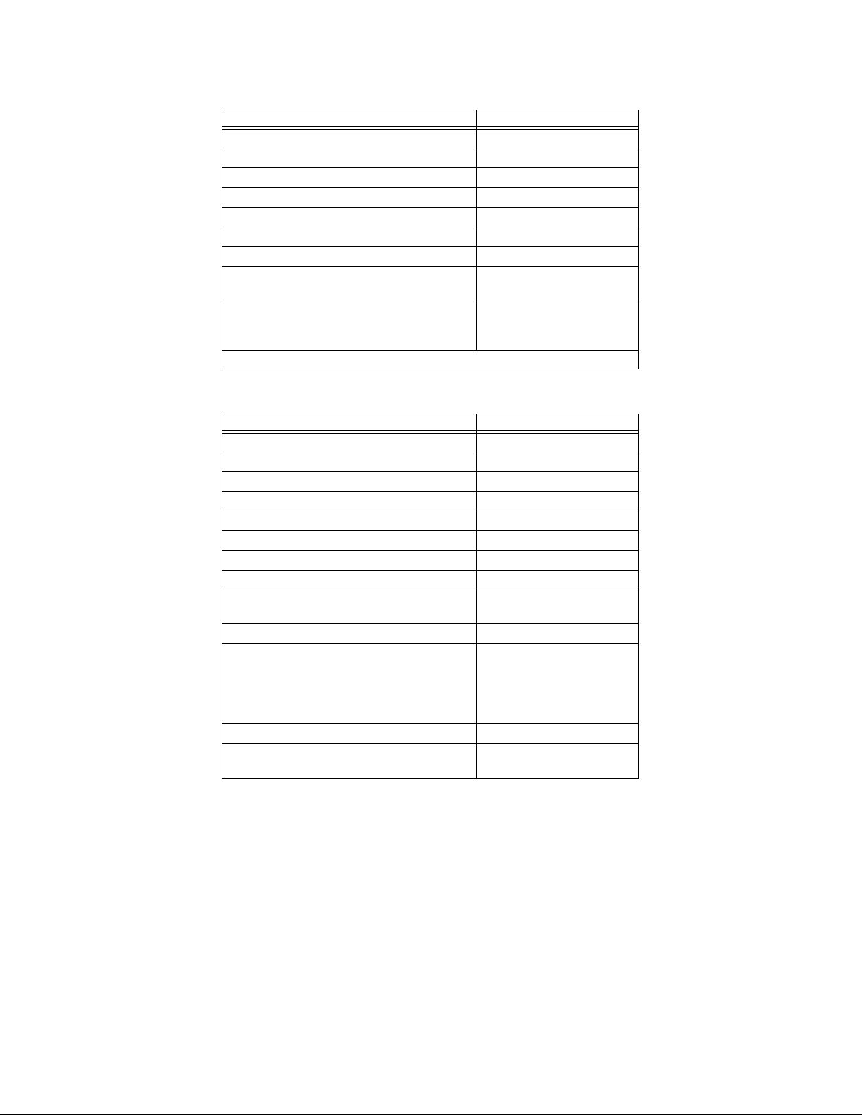
Selects WATCHDOG test.
RETURN key
Runs the WATCHDOG test.
After running the test, the sign will display the messages that are programmed in it.
Setting sound volume
PROGRAM key
SELECT key
SELECT key
SELECT key
SELECT key
SELECT key
SELECT key
RETURN key
SELECT key
This is for diagnostics only. Do not use this setting.
SELECT key
Press the U key to turn volume up.
Press the D key to turn volume down.
The “00” shown here changes accordingly.
NOTE: This is a temporary setting only. It can be used
as described in “Speaker volume control” on page 9.
SELECT key
RUN key The sign will display the messages
When you press this . . . You’ll see this on the sign . . .
PROGRAM
TURN OFF
RUN DEMO/TIME
SET TIME
SET DATE
CLEAR MEMORY
TEST MENU
WATCHDOG
The sign will display the
information in “Checkout
procedure” on page 24.
When you press this . . . You’ll see this on the sign . . .
PROGRAM
TURN OFF
RUN DEMO/TIME
SET TIME
SET DATE
CLEAR MEMORY
TEST MENU
WATCHDOG
DIP
VOLUME
VOLUME = 00
TEST MENU
that are programmed in it.
13
Page 14
Networking
AlphaPremiere™ series signs can be connected together so that messages can be sent to each of the signs
on the network. There are three ways to network AlphaPremiere™ series signs:
• RS232 (only available with the Standard Configuration) — This type of sign network allows “point-topoint” communication. This means that a single PC can be connected to a single sign. The length of
this network is limited to 50 feet.
• RS485 (available with both Standard and optional Ethernet Configurations) — This type of sign
network permits communication to a single or to multiple signs. The length of this network can be
4000 feet @ 9600 baud.
• Ethernet (only available with the optional Ethernet Configuration) — This sign network allows
connection of almost an unlimited number of signs over a virtually unlimited network length.
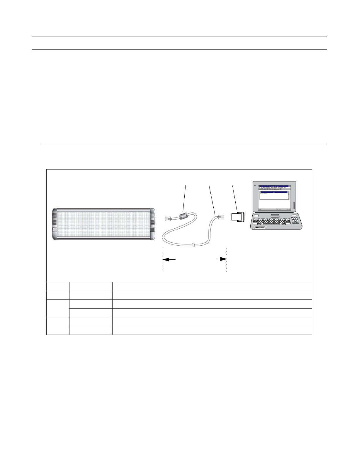
RS232
The diagram below shows how to connect a sign to your PC, through the PC’s RS232 jack. The PC can not
be separated from the sign by more than 50 feet, due to signal loss in the cable:
ABC
AlphaPremiere™ 9000 series sign
To sign’s
RS232 jack
Data signals get lost if
RS232 cable is longer
than 50 feet.
Item Part # Description
A
— Ferrite (ferrite end towards sign)
1088-8625 25-foot 6-conductor RS232 data cable
B
1088-8627 50-foot 6-conductor RS232 data cable
4370-0001C 25 pin sub-D/to 6 pos. RJ11 adapter
C
1088-9108 9 pin sub-D/to 6 pos. RJ11 adapter
To one of the
PC’s COM
(RS232) ports
MK
PC running
AlphaNET plus™ or
other messaging software
NOTE: You can not use the IR
remote to program messages
14
Page 15
RS485
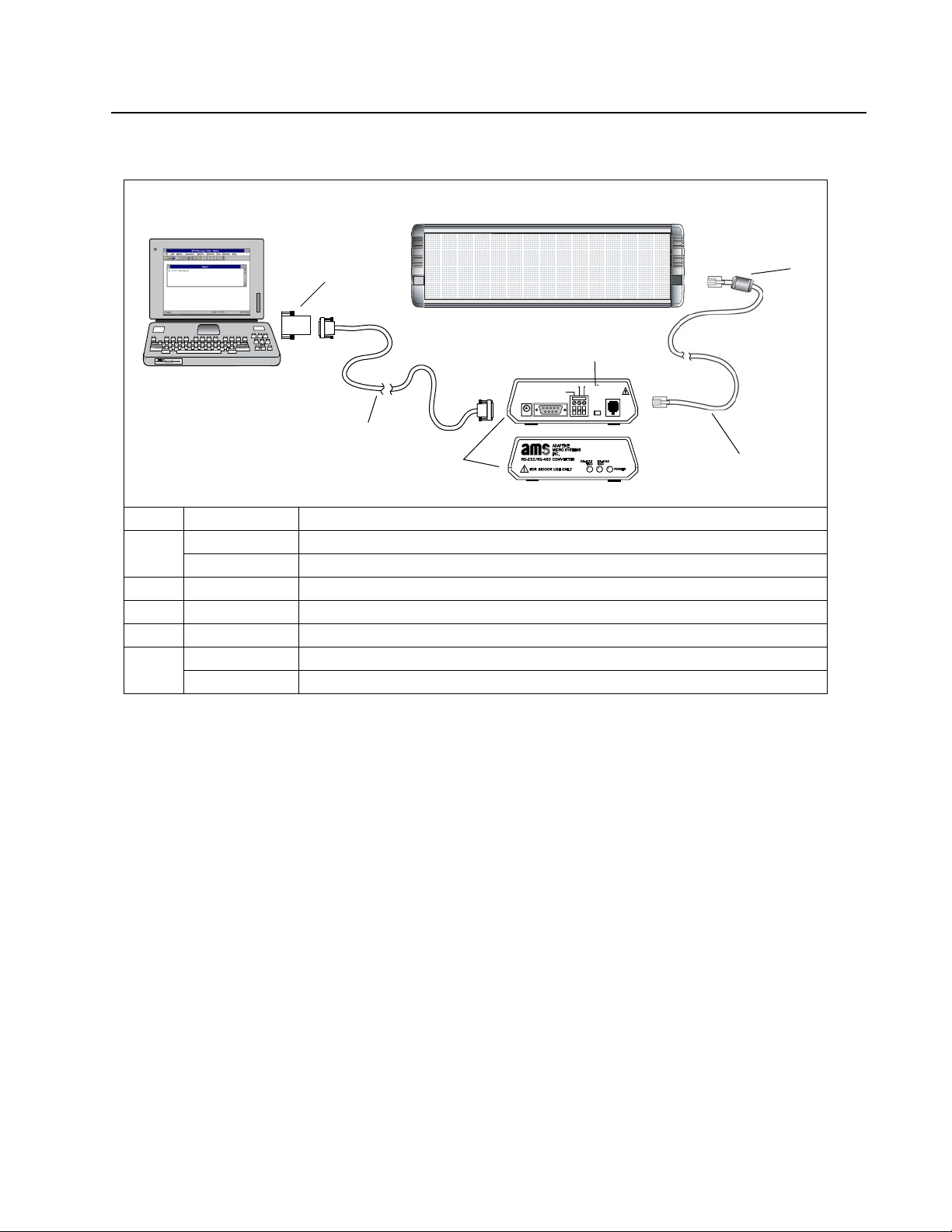
Refer to the Network Configurations manual for information on cabling requirements and connecting
multiple signs.
AlphaPremiere™ 9000 series sign
MK
A
Set switch to
unterminated
To one of
PC running
AlphaNET plus™ or
other messaging software
NOTE: You can not use the IR
remote to program messages
the PC’s
COM
(RS232)
ports
9 VOLTS AC
~NOMINAL
B
C
RS-485(+)
BLACK
SHIELD
RS-232
Item Part # Description
4370-0001C 25 pin sub-D/to 6 pos. RJ11 adapter
A
1088-9108 9 pin sub-D/to 6 pos. RJ11 adapter
B
1088-8634 10-foot 9-pin to 9-pin, type “A9” RS232 data cable. (Other lengths available; see table above.)
C
1088-1111 Converter Box III
D
1088-8000 4-conductor RS485, bulk cable
1088-8624 8 foot, 4-conductor RS485 cable, ferrite end closer to sign
E
1088-8636 1 foot, 4-conductor RS 485 cable, ferrite end closer to sign
RS-485( )
RED
To sign’s RS485 jack
E
NOT A
TELEPHONE
CONNECTION
RS-485
UNTERMINATED
TERMINATED
D
15
Page 16
Ethernet
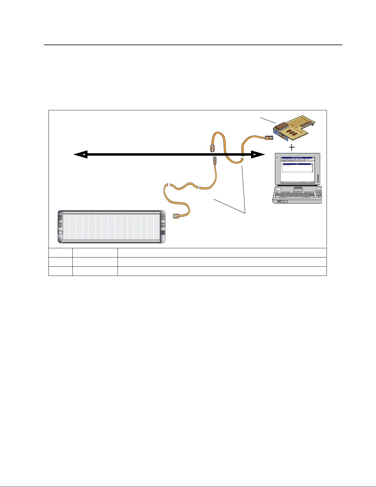
NOTE: A network administrator should be involved in connecting the sign to the Ethernet.
The optional configuration for the AlphaPremiere™ 9000 sign includes an internal 10BASE-T Ethernet
card with an external RJ45 jack. An IP address must be assigned to a sign. See “Setting a sign’s TCP/IP address” on
page 17.
Network connection
B
10BASE-T Ethernet network
MK
AlphaPremiere™ 9000 series sign
To sign’s Ethernet jack
Item Part # Description
A
— Ethernet cabling (not supplied)
B
— Ethernet card for PC (not supplied)
A
AlphaNET plus™ or
other messaging software.
NOTE: You can not use the IR
remote to program messages
PC running
16
Page 17
Setting a sign’s TCP/IP address
Before you can begin to use an AlphaPremiere™ sign on a Ethernet network, the display must be assigned
a unique TCP/IP address.
NOTE: The Alpha® Ethernet option inside the display is shipped with a default address of 010.11.11.1.
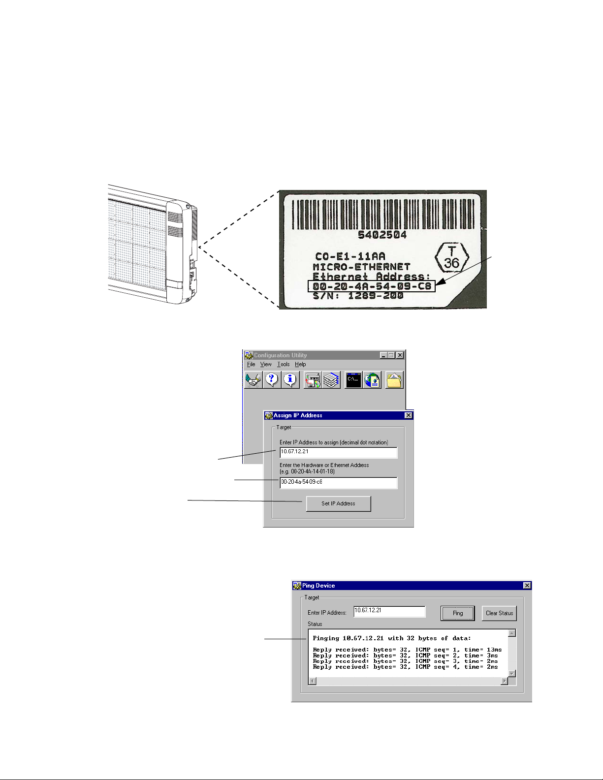
To set a new IP address, follow these steps:
1. Get a unique IP address from your network administrator. An example of an IP address is: 10.67.12.21.
2. Write down the 6-digit Ethernet address found on the Ethernet option label the back of your sign. For
example, the Ethernet address for the following label is: 00-20-4A-54-09-C8.
3. Using the Configuration Utility software supplied with the sign, select Tools > Assign IP . . . :
This label is
on the back
X
U
32/A
2
XD
R
D
X
T
6
X
U
A
/
2
3
2
RS
5
8
4
S
R
4
2
r
k
p
S
t
u
O
n
g
i
S
t
e
s
e
R
5
8
RS4
of Ethernetequipped
signs.
Ethernet address
Enter the IP address from step 1.
Enter the Ethernet Address from step 2.
Click Set IP Address.
4. Next, select Tools > Ping Device . . ., enter the sign’s IP address, and click on Ping to make certain that
the IP address you just assigned works.
If a reply from the sign is not received, try assigning
the address again by repeating the previous steps.
17
Page 18
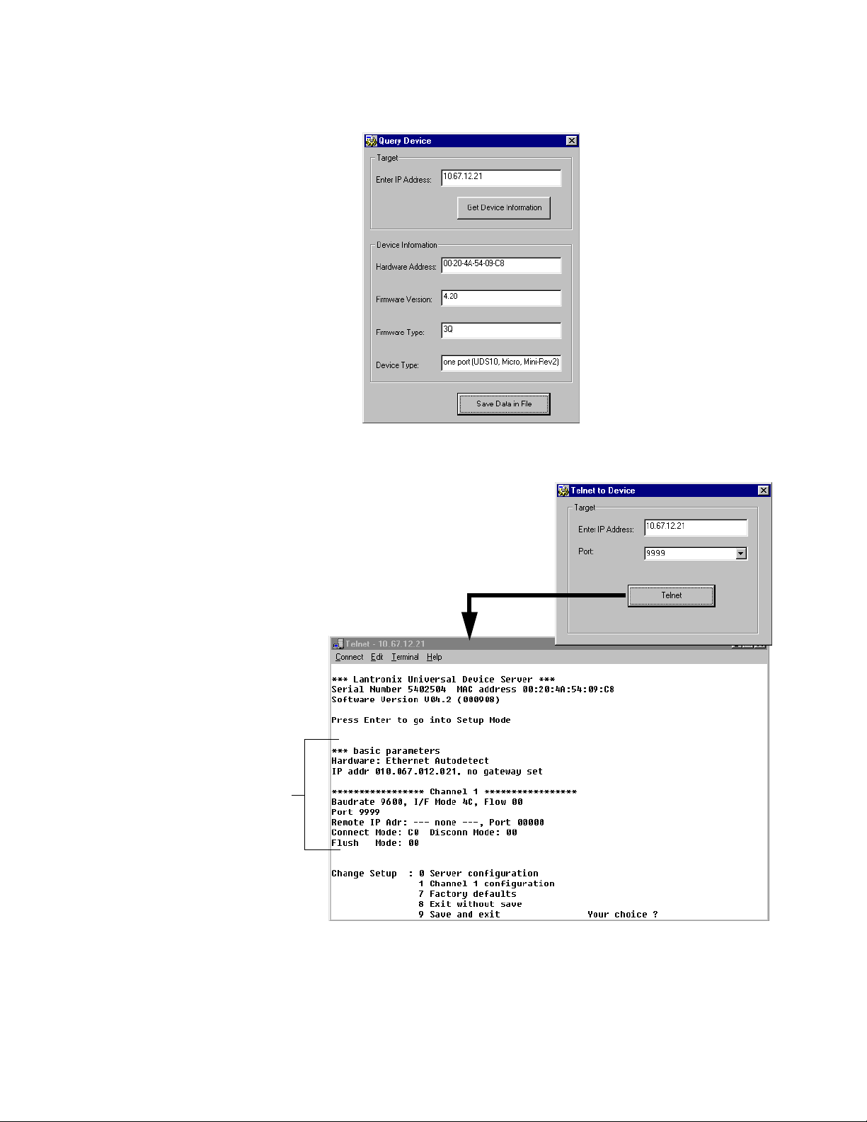
5. After the sign has an IP address assigned to it, you can:
• select Tools > Query Device . . . to get information about the sign’s Ethernet status:
• select Tools > Telnet to Device . . . to set various Ethernet parameters:
Baudrate, I/F Mode, Flow, Port,
etc. are all Channel 1 parameters.
Typically, you would only need to
set the Baudrate and I/F Mode
parameters.
18
Page 19
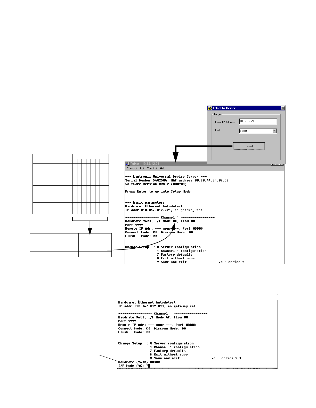
Setting Baud rate and Data format on an Ethernet-equipped sign
On signs that are Ethernet equipped, the Baud rate and Data format of the sign’s internal Ethernet card
must be identical to the Baud rate and Data format of:
• the sign’s internal DIP switches. See “Sign configuration” on page 6.
• the computer that is running the messaging software used to send messages to the sign.
To change the Baud rate and Data format of the sign’s internal Ethernet card, follow these steps:
1. Using the Configuration Utility software supplied with the sign, select Telnet to Device. The current
Baud rate, Data format (called I/F Mode), and other communication parameters will be displayed:
Parameters of the sign’s internal Ethernet card:
• Baudrate 9600 – Factory setting. Can be changed.
• I/F Mode (see table below) – This is a hexadecimal
number (4C in this example) that sets the network
type (RS232, internal to the sign), number of data bits
(7/8), parity (None/Odd/Even), and number of stop
bits (1/2).
Data format (I/F Mode) table
Binary Code
76543210
00
10
11
00
11
01
01
11
Network
Type
Number of
Data Bits
Parity
Number of
Stop Bits
Option
RS232
7 bit
8 bit
None
Even
Odd
1 bit
2 bits
Examples:
Options Binary Code
RS232, 8-bit, No parity, 1 stop bit 01001100 4C
RS232, 7-bit, Even parity, 1 stop bit 01111000 78
2. Select 1 for Channel 1 Configuration. Then set the various parameters as you are prompted:
In this example, the new
Baud rate will be 38400.
Hexa-
decimal
Number
19
Page 20

Installation
Environmental requirements
Care must be taken to observe these considerations when selecting a location for the sign.
• These signs are for indoor use only and should not be continuously exposed to direct sunlight.
• These signs should only be used in an environment where the temperature is between 0 and 50
degrees Celsius (32° to 122° F.)
• These signs should only be used in an environment where the humidity (non-condensing) does not
exceed 95%.
• For installation, there must be at least 1” (2.5 cm) clearance on each end of the case and at least 2”
(5.1 cm) clearance above the case.
Reducing electrical noise
These procedures are recommended to decrease the amount of electrical emissions and noise with the
AlphaPremiere™ 9000 signs:
•A sign should be connected to its own branch circuit.
• The input power source should be protected by a circuit breaker rated at no more than 20 amperes,
with no more than 4 signs connected together through a single circuit breaker.
• Incoming power to a sign should be routed on a path separate from a sign’s serial communication
wires. Do NOT run the power and communication wires in the same conduit.
•Where power and serial communications wires must cross, the intersection should be perpendicular.
• All serial communication wires should be shielded. The shield should only be connected to ground at
the RS485 converter box.
Checking speaker volume
Before mounting the sign, you should check the volume setting of the speakers, as described in “Speaker
volume control” on page 9.
Wall mounting instructions
Guidelines
Wall-mounting brackets are provided with the sign. Fasteners are supplied to attach the brackets to the
sign. However, fasteners to attach the sign to a wall are not supplied.
The specific type of fastener needed depends on the physical characteristics of the wall (e.g., concrete,
brick, wood) to which the sign is being mounted. Do NOT install directly to drywall, plasterboard, or other fragile
supports.
• Fasteners for wall-mounting brackets must be appropriate for the type of wall to which the sign will
be mounted.
• Each one of the fasteners must be capable of supporting four (4) times the weight of the sign.
•A sign must be attached to a wall (or to a wall-mounted support system) capable of bearing at least
four (4) times the weight of the sign.
Directions
1. Disconnect power from the sign.
2. Remove the two screws from each end cap.
NOTE: There are speaker wires behind the right end cap, so be careful to keep one hand on the end
cap—continuing to hold it in place—after removing the screws. Pull the end caps away
slowly, so you don’t accidentally snag the wiring or damage other components near the cap.
20
Page 21
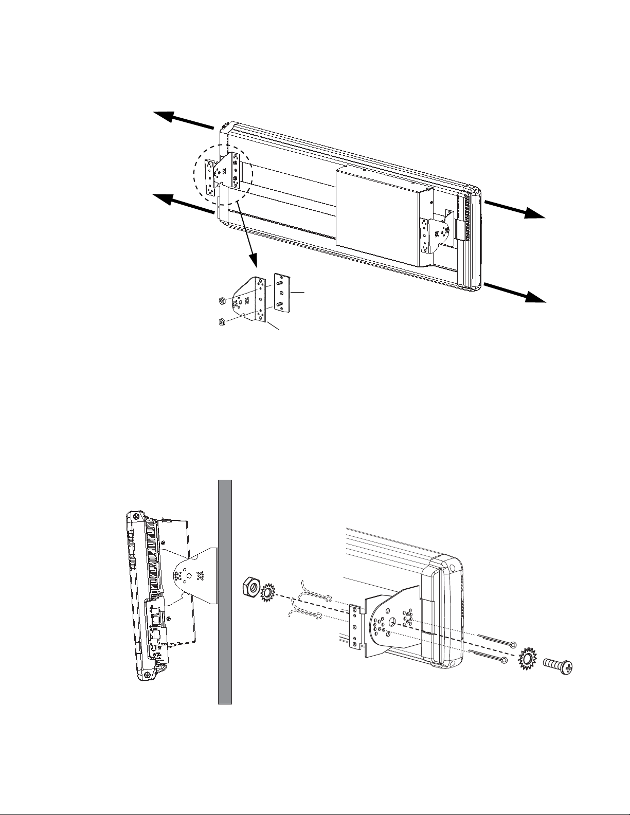
3. When the end caps have been removed, place each sliding bracket into the channel in the back of the
sign. Use two (2) Keps fasteners to attach a mounting bracket to each sliding bracket. Tighten the Keps
fasteners to 24 lb-in, 2.7 Nm:
Remove end cap and
place sliding bracket
into channel.
Remove end cap and
place sliding bracket
into channel.
Sliding bracket
Keps fasteners
Tighten the Keps fasteners
to 24 lb-in, 2.7 Nm.
Mounting bracket
4. Attach the remaining two (2) mounting brackets to a wall.
NOTE: Do NOT install a sign directly to drywall or plasterboard.
NOTE: No fasteners are provided for the outer set of mounting brackets. The fasteners selected must
be able to support four (4) times the weight of the sign.
5. Mount the sign on the wall. Use the supplied fasteners and cotter pins to attach the sign mounting
brackets to the wall mounting brackets:
After the best viewing angle for the sign has been selected and cotter pins have been
inserted and bent, tighten the 5/16” (7.94 mm) fasteners to 60 lb-in, 6.8 Nm.
6. Replace the end caps. Be careful not to pinch any internal wires or catch other components between
the lip of the end cap and the housing. Tighten end cap screws to 14 lb-in, 1.58 Nm.
21
Page 22
Ceiling mounting instructions
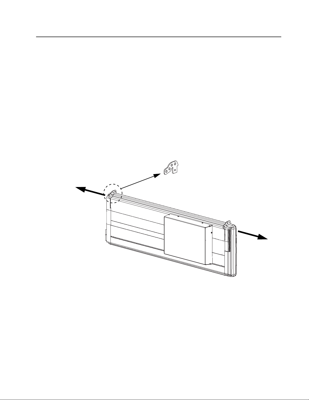
Hook support
Remove top end cap
screw and slip the hook
support into groove.
Remove top end cap
screw and slip the hook
support into groove.
Guidelines
A ceiling mounting bracket is not provided with the sign. Fasteners to attach the sign to a ceiling are also
not supplied.
The specific type of fastener required will vary depending on the physical characteristics of the material
(e.g., concrete, brick, wood) to which the sign is being mounted. Do NOT install directly to drywall, plasterboard,
or other fragile support.
• Fasteners for ceiling mounting brackets must be appropriate for the type of construction and material
to which the sign will be mounted.
• Each of the fasteners must be capable of supporting four (4) times the weight of the sign.
•A sign must be attached to an overhead support capable of supporting four (4) times the weight of the
sign.
• For adequate ventilation allow at least 1 inch (2.54 cm) clearance all around the sign.
Directions
1. Disconnect power from the sign.
2. Remove the upper screw from each end cap. Slip the bottom of one hook support into the grooves
between the tops of each end cap and the main housing:
3. Replace each end cap screw. Make sure that the screw has gone through the hook support. Tighten
4. Mount ceiling attachments (not supplied).
5. Attach hook supports to ceiling attachments. (Connection material not supplied.)
22
screw to 14 lb-in, 1.58 Nm.
Page 23
Counter mounting instructions
Guidelines
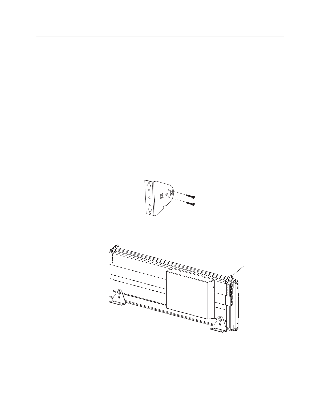
Counter mounting brackets are supplied with the sign. Fasteners to attach the mounting brackets to the
sign are supplied. However, fasteners to attach the mounting brackets to a counter are not supplied.
The specific type of fastener needed will vary depending on the physical characteristics of the counter
(e.g., concrete, brick, wood) to which the sign is being mounted. Do NOT install directly to drywall, plasterboard,
or other fragile supports.
• Fasteners for counter-mounting brackets must be appropriate for the type of counter to which the sign
will be mounted.
• Each one of the fasteners must be capable of supporting four (4) times the weight of the sign.
•A sign must be attached to a counter capable of bearing at least four (4) times the weight of the sign.
Directions
1. Disconnect power from the sign.
2. Remove the two screws from each end cap.
NOTE: There are speaker wires behind the right end caps so be careful to keep one hand on the end
cap—continuing to hold it in place—after removing the screws. Pull the end caps away
slowly, so that you don’t accidentally snag the wiring, or damage other components behind
the cap.
3. When the end caps have been removed, using the screws and nuts provided, loosely fasten two screws
in each mounting bracket as shown below:
Mounting bracket
4. Next, slide the screw heads on each mounting bracket into the channel in the back of the sign. Then
tighten the screws on each bracket:
Sign is shown with ceiling
mounting brackets attached.
5. Replace the two screws in each end cap. Tighten each screw to 14 lb-in, 1.58 Nm.
6. Fasten each mounting bracket to the counter. (Connection material not supplied.)
23
Page 24

Checkout procedure
After installing a sign according to the previous sections, make sure the unit is installed properly by
applying power to it. Information similar to the following should be displayed on the sign:
9000 SERIES
9200 RED
SERIAL ADDRESS
00 HEX
SERIAL DATA
9600, 8n1
RS485 ECHO
DISABLED
INFRARED
ENABLED
SPEAKER VOLUME
[XXXX ]
PERF REV
211040001B v01.04
FPGA REV
26111401 V1.4
RAM 1
RAM 128K
10:48 AM FRI.
FEB. 23, 2001
FLASH OK
Service and maintenance
Firmware updates
The internal program or firmware (also referred to as “flash EPROM”) that runs an AlphaPremiere™ sign
may need to be updated from time to time.
To find out the availability of any updates, check this web page:
http://www.adaptivedisplays.com/support.htm.
Routine cleaning
When cleaning the case is necessary, use a soft lint-free cotton cloth (such as a pre-washed cotton diaper)
with mild soap and water. Two drops of soap per quart of water is adequate. Alcohol and cleaners with alcohol (or
any other strong solvent) are not recommended.
If the front lens becomes dusty, use a vacuum cleaner that has a soft brush on an extension wand.
24
 Loading...