

Page 1
R
INSTALLATION
GUIDE
AVA-2904
PCI-TO-FAST SCSI CARD
Page 2
INTRODUCTION
The AVA®-2904 PCI-to-Fast SCSI Card enables you to connect
up to seven SCSI devices—such as scanners and CD-ROM, CDR,
CDRW, and DVD drivers—to Microsoft operating systems (OSs).
The Adaptec drivers are embedded within the Microsoft OS as
AIC-7850. Alternately, the drivers can be downloaded from
Adaptec’s Web site—http://www.adaptec-europe.com or
http://www.adaptec.com—using the driver download option.
Technical Specifications
OSs Supported: DOS, Windows 95/98/Me/NT/2000
PC Bus Type: 32-bit PCI
Interface Transfer Method: Bus Master DMA
Data Transfer Rate: 10 MB/sec
Supported Protocol: SCSI-1, SCSI-2, and Fast SCSI-2
Peripheral Support: Nonbootable
Total Devices Supported: 7 total (internal or external)
External Connector: 50-pin high-density SCSI-2 (female)
Internal Connector: 50-pin standard (male)
(Direct Memory Access)
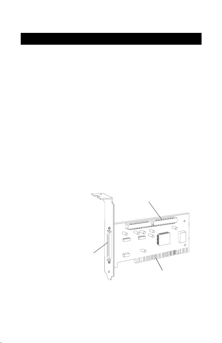
50-pin internal SCSI connector
50-pin high-density
external SCSI connector
AVA-2904 PCI-to-Fast SCSI Card
PCI bus contacts
1
Page 3
Installation Guide
Goal of this Installation Guide
This installation guide explains how to install and use your new
AVA-2904 SCSI Card. Once you have performed the installation
steps described in this guide, your AVA-2904 SCSI Card and
SCSI devices are ready for operation.
If you are not connecting the full complement of seven devices
during your initial installation, when the time comes to add
another peripheral, this guide will help with that installation.
As such, we recommend that you keep this guide with your
important computer documents. Feel free to refer to the Adaptec
Web site for access to an online copy if the need arises.
This installation guide provides step-by-step instructions for:
• Installing the AVA-2904 PCI-to-Fast SCSI Card
• Connecting internal SCSI devices
• Preparing and connecting the external SCSI devices
• Installing the AVA-2904 SCSI Card driver software
INSTALLATION AND SETUP
Be sure to take the following precautions before you begin
installing your new AVA-2904 SCSI Card:
STEP 1
2
WARNING
Tu r n OFF power to the computer and disconnect
the power cord!
Always handle the SCSI card by its metal bracket or by the card
edges. Do not touch the gold connector or any of the components
on the card.
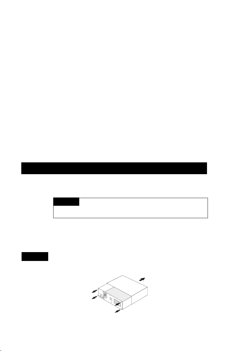
After turning off power to your PC and unplugging the power
cord, remove the cover from the computer case. (If necessary,
refer to the instructions in your computer documentation.)
View from back
of your computer
Page 4
AVA-2904 PCI-to-Fast SCSI Card
STEP 2
STEP 3
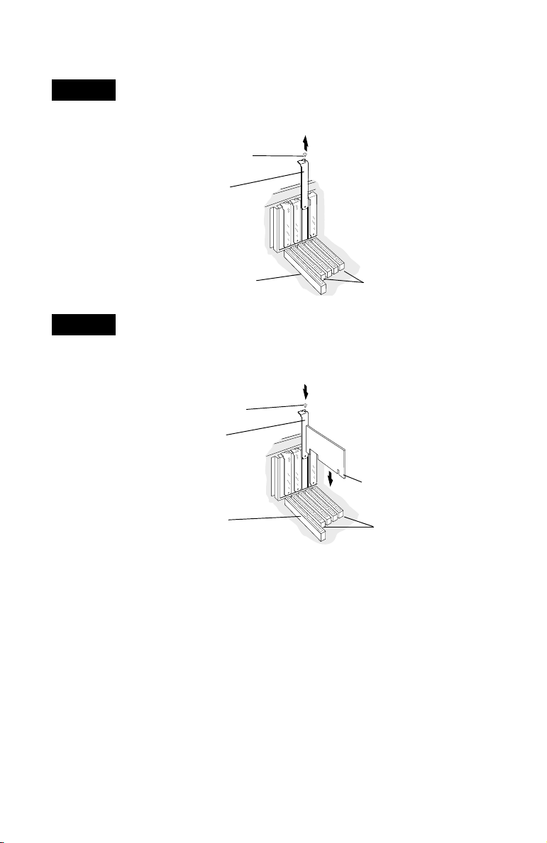
Locate an unused PCI expansion slot (typically white or ivory).
Unscrew and remove the expansion slot cover that protects the
card-slot opening. Save the slot cover screw for use in Step 3.
Expansion slot
bracket screw
Expansion
slot cover
16-bit ISA
expansion slot
(typically black)
PCI expansion
slots (typically
white or ivory)
Align the AVA-2904 SCSI Card over the PCI slot and lower the
card into the slot. Press it down firmly so that the bus contacts are
securely seated in the slot. Secure the card bracket with the screw
you removed in Step 2.
Expansion slot
bracket screw
SCSI card
bracket
Bus contacts
16-bit ISA
expansion slot
PCI expansion slots
3
Page 5
Installation Guide
CONNECTING SCSI DEVICES
You can connect a total of seven SCSI devices to the AVA-2904
SCSI Card.
Whether installing internal or external devices to a SCSI card, be
certain that all devices are assigned a unique SCSI ID from 0 to 6.
Some instruction is supplied here; however, it is best to doublecheck with each device’s manufacturer’s instructions for correct
location and proper device ID setting.
NOTE
The card’s SCSI ID is preset to 7 and cannot be changed.
Connecting Internal SCSI Devices
You must prepare each internal SCSI device for installation.
(If you are installing external SCSI devices only, skip to
Connecting External SCSI Devices on page 7.)
NOTE
If only external devices are being connected to the
AVA-2904 SCSI Card, do not use the 50-pin ribbon cable.
STEP 1
STEP 2
STEP 3
4
Using the SCSI ID selector, make sure all internal SCSI devices
are assigned a unique ID number ranging from 0 to 6. Refer to the
device’s documentation for instructions on setting the SCSI ID.
Install and mount each internal SCSI device in an available drive
bay inside your computer. (Refer to your computer and device
documentation for instructions.)
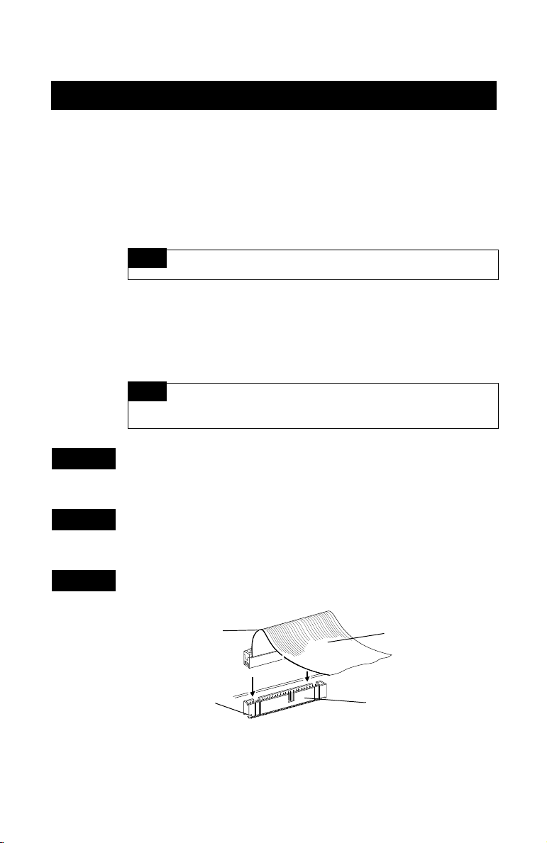
Connect one end of the cable into the SCSI connector. It should
fit snugly into the notched connector along the top of the card.
Coloured
stripe
Pin 1
50-pin SCSI
ribbon cable
Internal SCSI
connector
Page 6
.
STEP 4
AVA-2904 PCI-to-Fast SCSI Card
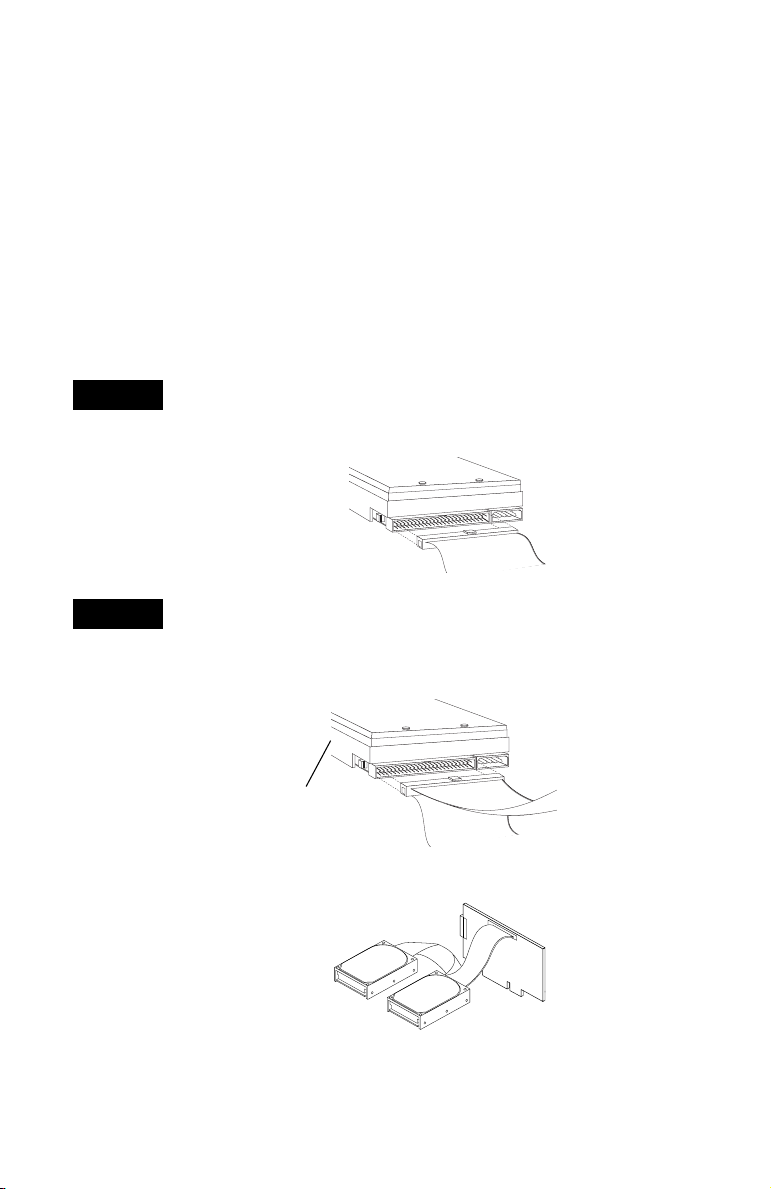
• If you purchased your SCSI card in an Adaptec kit, an
internal SCSI cable that allows you to connect up to two
internal SCSI devices is included. If you are connecting more
than two internal SCSI devices, you must obtain a 50-pin
internal SCSI cable with enough connectors to accommodate
any additional devices.
• Make sure the coloured stripe on one side of the cable is
aligned with pin 1 of the card’s connector. Pin 1 on the
connector is usually designated by a small triangle (▲), or a
“1” on the connector. The SCSI card’s internal connector is
also keyed to ensure the cable is not plugged in backwards.
Plug the other end of the cable into the internal device. If this
device is the only (or final) one, it must be terminated. Refer
to manufacturer’s instructions for device termination.
STEP 5
Plug any remaining connectors on the cable into any other
internal devices, provided you have any others to include.
Any devices located between the SCSI card and the last device
must not be terminated (as shown in the following figures).
Unterminated
internal SCSI device
Termina tion
Enabled
Termina tion
Disabled
To first internal
SCSI device
To SCSI card
5
Page 7
Installation Guide
If indeed you’ve only one device, you must attach it to the end of
the cable. Remove (or disable) terminators on all devices that you
plan to install in the middle of the cable (as shown in the figure at
the bottom of page 5).
On most internal SCSI devices, the termination setting is controlled
by setting a jumper or a switch, or by physically removing or
installing a resistor module(s). Refer to the device’s documentation
to determine how to enable or disable termination on your
particular device.
STEP 6
STEP 7
STEP 8
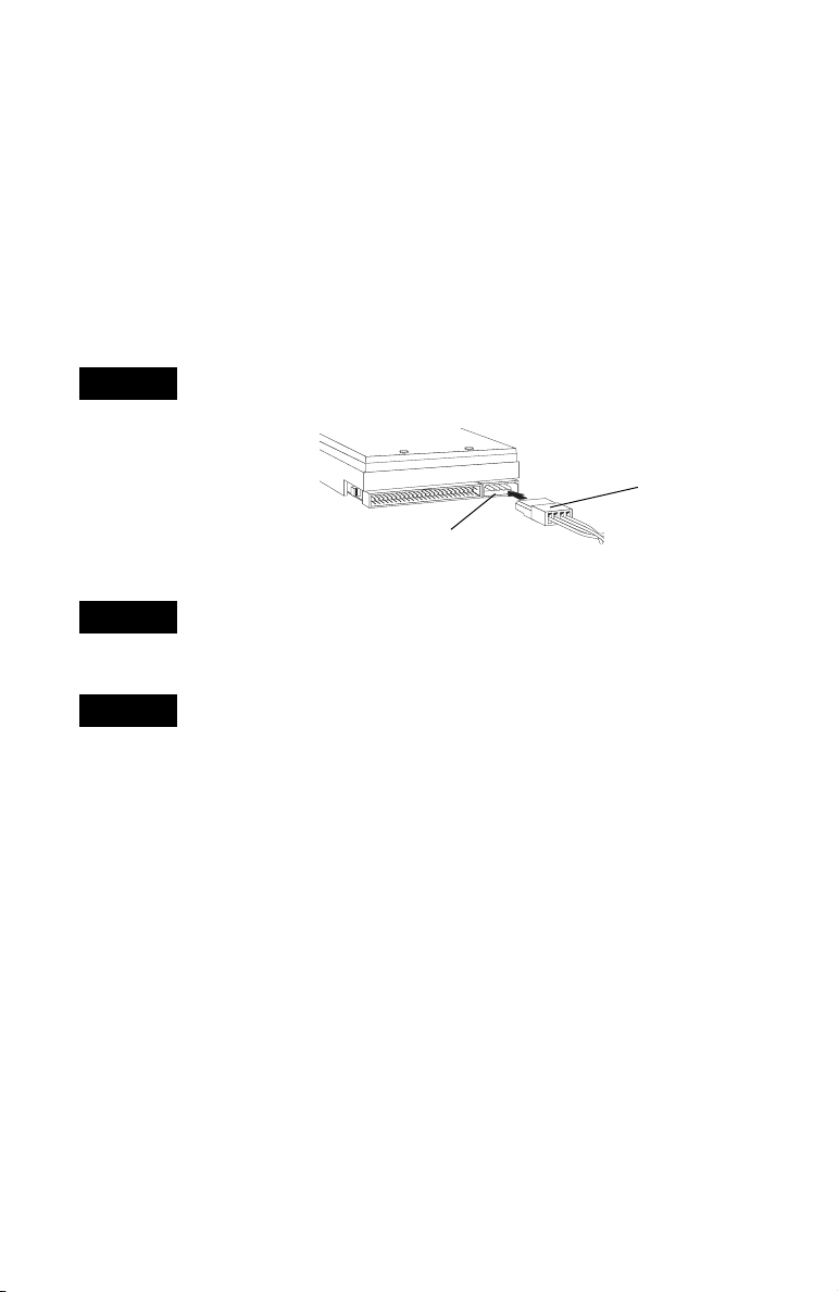
Connect an available DC power cable (from your computer’s
power supply) to the power input connector on the SCSI device.
DC power cable
(from the power supply)
Power input connector
on the back of the drive
Unless you have external devices to connect, replace computer
cover, and connect all power cables to the computer. Now you
are ready to start your computer.
Windows 95, 98, Me (Millennium Edition), NT, and 2000 will
automatically install the appropriate software driver for your
operating system from an embedded list in your PC’s operating
system (OS). (For information regarding the automatic
installation of the software driver compatible with your
specific OS, go to Driver Software Installation on page 10.)
6
Page 8
AVA-2904 PCI-to-Fast SCSI Card
Connecting External SCSI Devices
If you are installing internal SCSI devices only, go back to
Connecting Internal SCSI Devices on page 4.
NOTE
If only external devices are being connected to the
AVA-2904 SCSI Card, do not use the 50-pin ribbon cable.
Set this cable aside for use with internal devices you might
wish to connect in the future.
External Connector Types
Several different types of SCSI connectors are used on SCSI
devices and each type requires a different kind of cable.
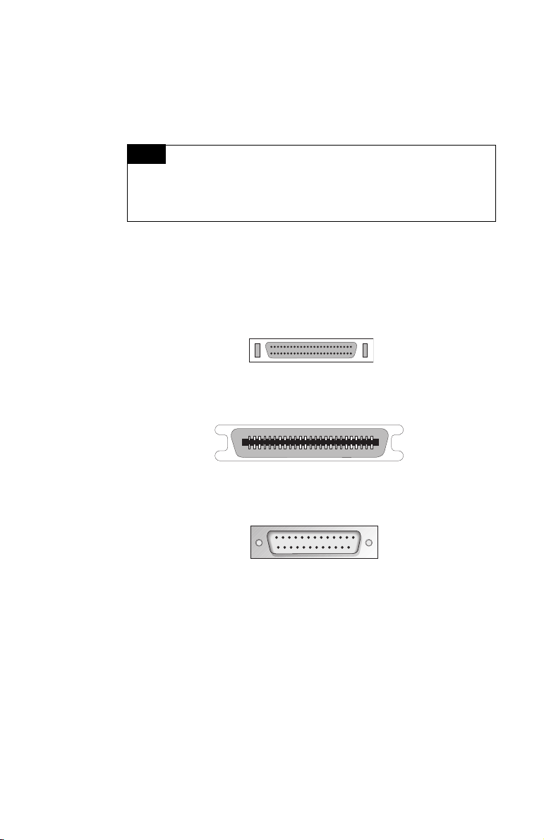
The card has a 50-pin high-density connector. The following
diagrams illustrate the different kinds of SCSI connectors.
SCSI-2 High-density 50-pin Connector*
Typically used with high-performance CD-ROM drives,
hard disk drives, Jaz drives, and Plug-and-Play devices.
SCSI-1, Low-density Centronics 50-pin Connector*
Used with many CD-ROM drives, hard disk drives,
SCSI tape drives, and scanners.
DB25 Connector*
Used with Iomega ZIP drives, Syquest EZFlyer, and similar devices.
* Connectors not portrayed to scale.
If you have a SCSI device with a DB25 connector, you can order
a DB25 cable from Adaptec to connect it to the AVA-2904 SCSI
Card. No external cables are provided with this kit. You can
order cables to fit your specific requirements from Adaptec or
any computer products supplier.
7
Page 9
Installation Guide
Procedure for Connecting External Devices
You must prepare each external SCSI device for installation.
STEP 1
STEP 2
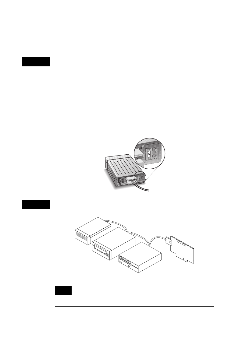
Using the SCSI ID selector on the back of the device, be certain
each external device is assigned a unique ID number ranging
from 0 to 6. Refer to the device’s documentation for instructions
on setting the SCSI ID.
After locating ID selector on the back of the device, click the
button on either the top or bottom of the area where number is
viewed (or possibly select from a rotary or dial configuration)
to select a higher or lower device number that is not being used
by any other device. For more information, refer to the device’s
documentation for instructions on setting the SCSI ID. Remember
that the card’s SCSI ID is set to 7 and cannot be changed.
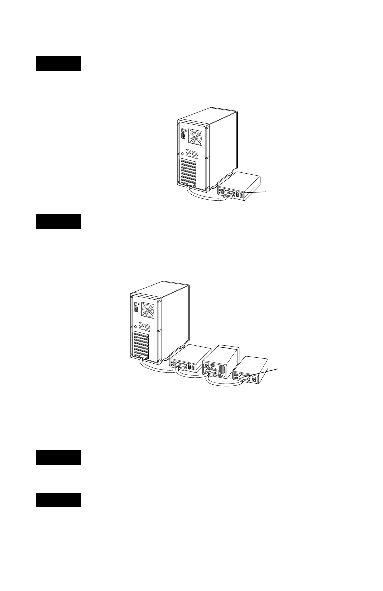
Join the external SCSI device(s), using an external SCSI-2 cable,
to the high-density 50-pin external connector.
Termina tion
Enabled
Termination
Disabled
Termination
Disabled
NOTE
For each external SCSI device you install, you must
obtain a high-quality, 50-pin external SCSI-2 cable.
8
Page 10
AVA-2904 PCI-to-Fast SCSI Card
STEP 3
STEP 4
Plug one end of the external SCSI cable into the card’s external
SCSI connector, and plug the other end of the cable into either
one of the SCSI connectors on the external SCSI device. (If you are
installing only one external device, attach a terminating plug to
the device.)
3
Terminating plug
Connect other external SCSI devices by connecting each device to
the previous device until all external SCSI devices have been
connected. Install (or enable) terminators on the last device in the
chain. Remove (or disable) terminators on all devices that you
plan to attach in the middle of the SCSI chain. (The device at the
end of the chain must be terminated.)
STEP 5
STEP 6
3
2
4
Terminated here
On most external SCSI devices, termination is controlled by
installing or removing a terminating plug. Refer to the device’s
documentation to determine how to enable or disable
termination on your particular device.
Reposition your computer cover on your PC. Connect all power
cables to the external devices and the computer. Turn on the
external devices, then turn
ON the computer.
Windows 95, 98, Me, NT, and 2000 will automatically install
the appropriate software driver for your OS from an embedded
list in your PC’s OS. (For information regarding the automatic
installation of the software driver compatible with your specific
OS, go to Driver Software Installation on page 10.)
9
Page 11
Installation Guide
DRIVER SOFTWARE INSTALLATION
As mentioned in the steps for connecting internal and external
devices, the OS will automatically install its compatible software
driver from an embedded list.
To access SCSI devices in DOS, download the dosdrvr.exe file
from Adaptec’s support Web site and follow the instructions
provided.
In other types of situations, the following may be helpful.
Windows 95 or 98
Once your AVA-2904 SCSI Card is installed and you have
restarted your system, Windows 95 or 98 prompts you through
the rest of the installation process. Follow these steps:
STEP 1
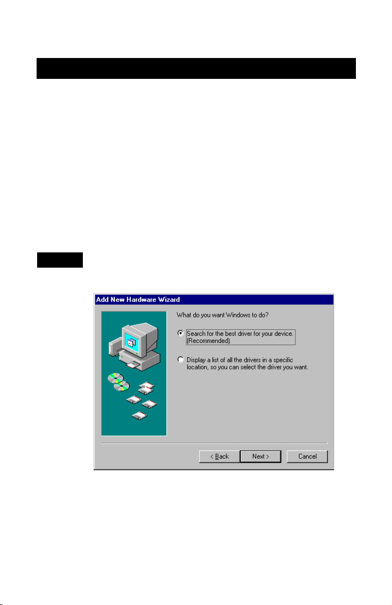
When the Add New Hardware Wizard setup window appears,
select the first radio button (instructing the setup wizard to
search for the driver best suited for your device), and click Next.
10
Page 12
AVA-2904 PCI-to-Fast SCSI Card
STEP 2
STEP 3
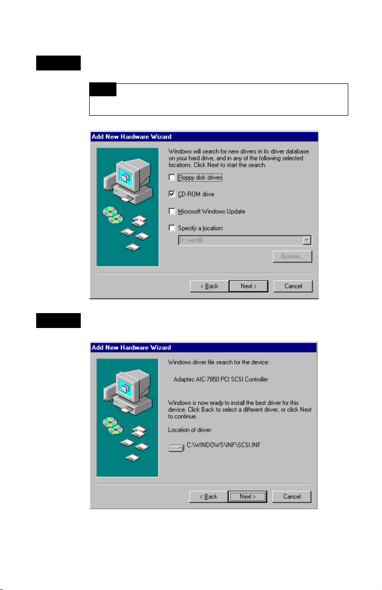
When the next setup wizard window appears, select (check)
the CD-ROM drive option from the list, and click Next.
NOTE
Be sure the Microsoft Windows 9x CD-ROM is in your
CD-ROM drive!
Your system locates the device and prompts you to continue
with the installation. Click Next.
11
Page 13
Installation Guide
STEP 4
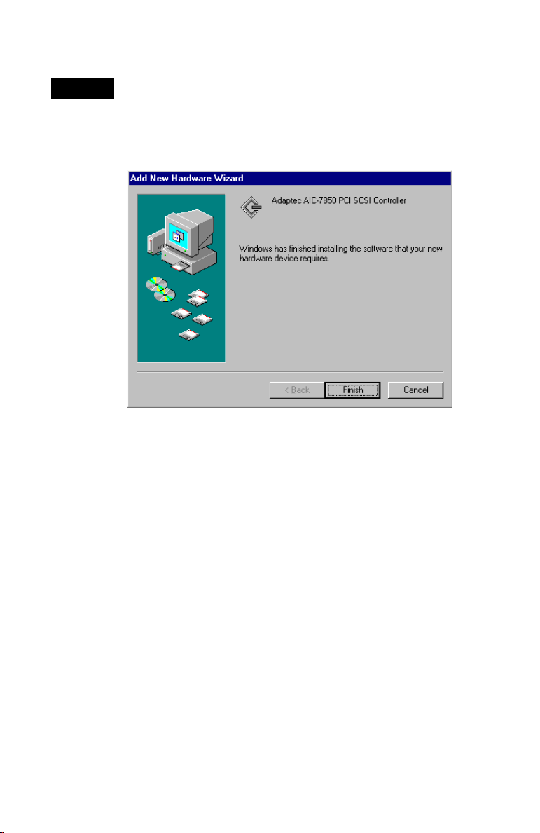
With Windows 9x installation, the AVA-2904 SCSI Card is
detected as AIC-7850. This is the integrated circuit chip on your
AVA-2904 SCSI Card.
Once the driver has been located and installed, the wizard
confirms completion. Click Finish.
Windows Me and Windows 2000
With Windows Me and Windows 2000, driver software
installation is fully automatic, including the identification
of compatible drivers.
The most current version of both OSs have embedded driver
support for the SCSI card as part of the installation software.
When the AVA-2904 SCSI Card is installed and you have
rebooted your computer, the Add New Hardware Wizard
setup window appears to walk you through the final steps.
For additional instructions on installing embedded driver
support, see the OS documentation.
12
Page 14
AVA-2904 PCI-to-Fast SCSI Card
STEP 1
STEP 2
STEP 3
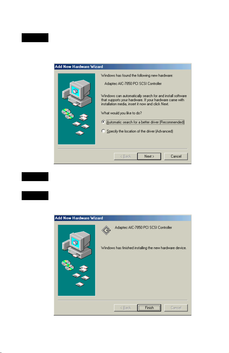
Once Windows Me or Windows 2000 has identified your new
hardware device, select the first radio button to launch an
automatic search through the list of embedded drivers for the
driver most suitable, and click Next.
Your OS locates the appropriate driver for the newly detected
device and automatically processes the installation.
The AVA-2904 SCSI Card is detected as AIC-7850. This is the
integrated circuit chip on your AVA-2904 SCSI Card. Once
installed, the wizard confirms completion. Click Finish.
13
Page 15

Installation Guide
With completion of this section, installation of your AVA-2904
SCSI Card and selection of drivers is complete. For more useful
information on configuring your SCSI devices and using your
AVA-2904 SCSI Card, refer to Using Your SCSI Card and SCSI
Devices on page 16.
Windows NT 4.0
The most current version of the Windows NT 4.0 OS has
embedded driver support for the AVA-2904 SCSI Card as
part of the installation software. Before you install the
Windows NT driver from the embedded list, download
either the latest Microsoft service pack or the Adaptec driver
file: 7800wnt.exe from the Adaptec support Web site at
http://www.adaptec-europe.com or http://www.adaptec.com.
For additional instructions on installing embedded driver
support, refer to the OS documentation.
After you have installed the AVA-2904 SCSI Card and have
restarted your computer, follow these steps:
STEP 1
14
Click the Start button, point to Settings, then select Control
Panel. From the Control Panel window, double-click SCSI
Adapters. The SCSI Adapters window opens.
NOTE
Although the title of the Control Panel window is
SCSI Adapters, the window also displays IDE buses. If a line
mentions IDE, ATA, ATAPI, UDMA, or Ultra DMA, the bus
referred to is not a SCSI bus.
Ignore the presence of these other buses as you configure the
Adaptec controller.
Page 16
AVA-2904 PCI-to-Fast SCSI Card
STEP 2
STEP 3
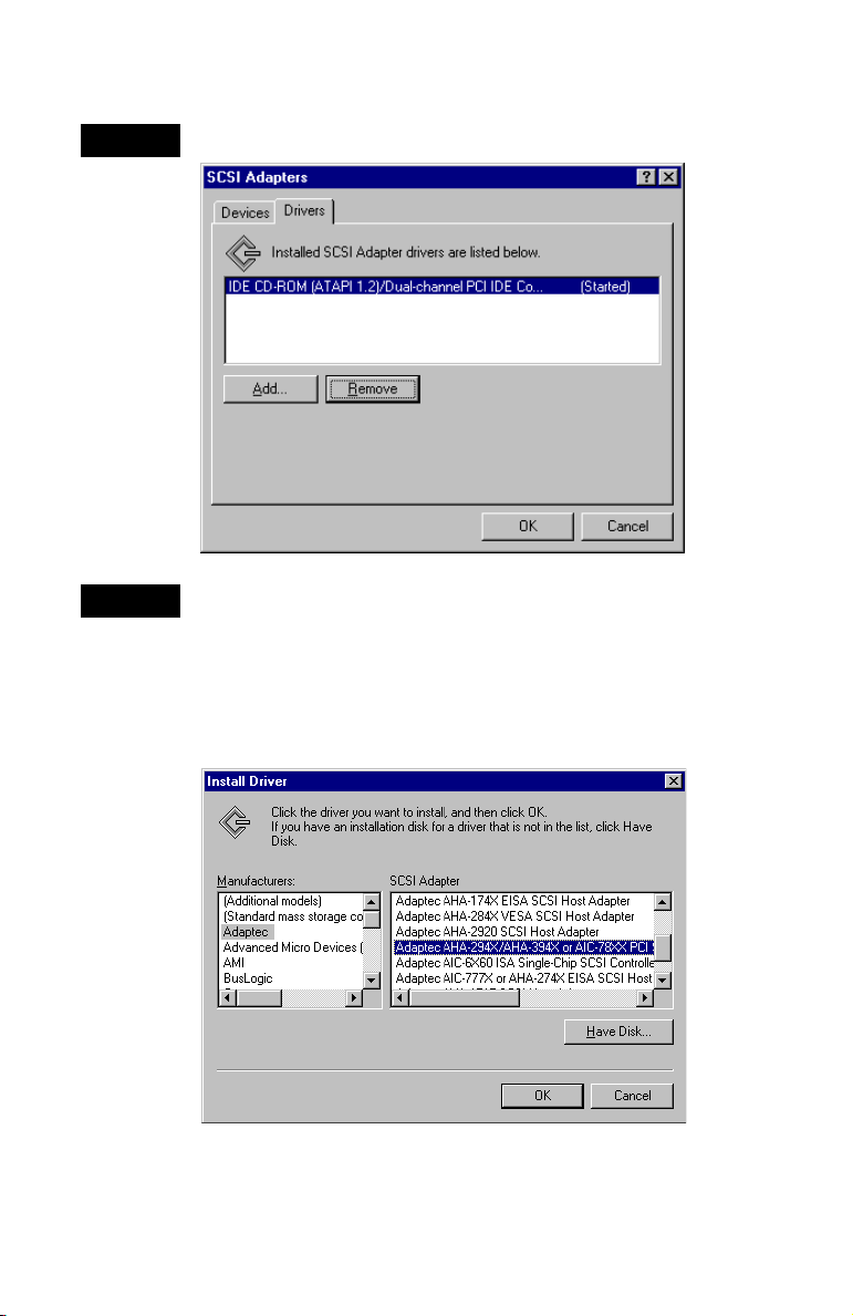
Go to the Drivers tab. Click Add.
The Install Driver window opens. From the Manufacturers: list
on the left, select Adaptec. From the SCSI Adapter list on the
right side, highlight the driver you wish to install, then click OK.
If the AVA-2904 SCSI Card does not show up in the list, select
the Adaptec AHA-294X/AHA-394X or AIC-78XX PCI SCSI
Controller. The AVA-2904 belongs to this family with its
AIC-7850 SCSI integrated circuit chip.
15
Page 17

Installation Guide
USING YOUR SCSI CARD AND SCSI DEVICES
Configuring SCSI Devices
• You may need to install the manufacturer’s proprietary
device drivers if you use SCSI devices other than hard disk
and CD-ROM drives. (See your device’s documentation.)
• For all SCSI devices connected to the AVA-2904 SCSI Card,
especially external devices, make sure to use high-quality
SCSI-2 cables to ensure reliable data transfer.
• When one or more Fast SCSI devices (SCSI devices that
support a data transfer rate of up to 10 MB/sec) are connected
to the AVA-2904 SCSI Card, the total length of all cables
(internal and external) must not exceed 3 m (9.8 ft). See your
device’s documentation to determine if it is a Fast SCSI device.
Hard Disk Drives
• The AVA-2904 SCSI Card does not support the Boot option,
and therefore does not display any Adaptec banner or Ctrl-A
message at computer initialization. To boot your system, a
bootable hard disk drive must already be installed on a
different disk controller card.
• Every SCSI hard disk must be physically low-level formatted,
partitioned, and logically formatted before it can be used to
store data.
If you connected a new SCSI hard disk drive to your SCSI
card, you must partition and logically format the drive.
For Windows 95 or 98, refer to your computer and
Windows 95 or 98 documentation. For other OSs, see
your OS documentation. SCSI hard disks are physically
formatted at the factory and do not usually need to be
physically formatted again.
16
Page 18

AVA-2904 PCI-to-Fast SCSI Card
Installing Multiple SCSI Cards
• Multiple SCSI cards can be installed in your computer; you are
limited only by the available system resources (for example,
IRQ settings, I/O port addresses, BIOS addresses, and so
forth) not used by other cards installed in your computer.
• Each SCSI card you install forms a separate SCSI bus with a
different set of SCSI devices. SCSI IDs can be reused as long
as the ID is assigned to a device on a different SCSI card
(for example, each card can have a device with SCSI ID 2).
Verifying that the Windows 95, 98, or Me
(Millennium Edition) Driver is Installed
To verify that the driver for the AVA-2904 SCSI Card is installed
properly in Windows 95, Windows 98, or Windows Me, follow
these steps:
STEP 1
STEP 2
STEP 3
STEP 4
STEP 5
Click the Start button, point to Settings, then click Control Panel.
Double-click the System icon.
Click the Device Manager tab.
Double-click the SCSI Controller icon.
If an exclamation point in a yellow circle or a red “X” appears
along with the driver, this indicates that the device is in a
problem state (usually a hardware conflict). Double-click the
icon to see the error message, then correct the problem.
17
Page 19

Installation Guide
Verifying that the Windows NT 4.0 Driver is Installed
To verify that the Windows NT 4.0 driver for the AVA-2904 SCSI
Card is installed properly, follow these steps:
STEP 1
STEP 2
STEP 3
STEP 1
STEP 2
STEP 3
STEP 4
From the Start menu, go to Settings, and select Control Panel.
From the Control Panel window, double-click SCSI Adapters.
The SCSI Adapters window opens.
Go to the Devices tab. If the adapter is displayed, the driver is
loaded. (Expanding the plus sign next to the adapter displays a
list of the devices connected to the adapter.)
Verifying that the Windows 2000 Driver is Installed
To verify that the Windows 2000 driver for the AVA-2904 SCSI
Card is installed properly, follow these steps:
Right click on the My Computer icon on your desktop.
Select Manage.
Click on Device Manager.
Go to the SCSI and RAID Controllers category. Be sure the
AVA-2904 SCSI Card is listed and that it doesn’t have any
red X’s, yellow !’s, or yellow ?’s.
18
Page 20

AVA-2904 PCI-to-Fast SCSI Card
SCSI Card Settings
The default SCSI card settings listed in the table below are fixed
and cannot be changed. These settings are appropriate for most
systems.
SCSI Card Settings Default
Card SCSI ID 7
SCSI Parity Checking Enabled
Transfer Rate 10.0 MB/sec
SCSI Card SCSI Termination Automatic
Enable Sync Negotiation Yes (Enabled)
Enable Fast SCSI Yes (Enabled)
Enabled Disconnection Yes (Enabled)
19
Page 21

Installation Guide
TROUBLESHOOTING
Most problems that occur with your SCSI card results from errors
in preparing and connecting devices on the SCSI bus. If you
encounter any problems either during or after installation, check
the following items first, as these situations are covered in this
installation guide:
• Are all SCSI devices powered on?
• Are all SCSI bus cables and power cables properly connected?
• Is the AVA-2904 SCSI Card firmly seated and secured in the
PCI expansion slot?
• Is pin 1 orientation maintained throughout the SCSI bus?
• Do the SCSI card and all devices on the SCSI bus have unique
SCSI IDs?
• Are all devices on the SCSI bus terminated properly?
• Does your system CMOS setup require you to enable PCI bus
parameters? If so, refer to your computer’s documentation for
instructions. Check that IRQ channel assignment, board, and
BIOS settings have been made.
Some configuration options apply to a specific PCI bus slot,
so if you change these options, be sure you are applying
them to the slot in which the SCSI card is installed.
Check your computer documentation to verify which slot
corresponds to what number.
• If there is an Interrupt Type or Interrupt Line option in the
Setup program, be sure to select Int-A or Interrupt Type
=A. Depending on your system design, you may also be
required to change a motherboard jumper setting.
• If there is a Triggering Interrupt option, be sure to select
Level.
• If there is an option to enable or disable bus mastering
for the PCI slots, be sure to select Enabled.
• If your computer has a combination of ISA (or EISA)
and PCI boards, you may need to mark the IRQs used
by ISA/EISA boards as Used so the system BIOS will
not try to assign these IRQs to other PCI boards.
20
Page 22

AVA-2904 PCI-to-Fast SCSI Card
• In some systems, the BIOS reserves a set of available IRQs
for PCI boards, and you must assign these IRQs manually.
• If you have not already done so, we recommend you
upgrade your motherboard BIOS by downloading the
latest version from the manufacturer ’s Web site.
NOTE
If you are experiencing problems with a specific SCSI
device when other SCSI devices are working correctly, please
contact the device’s manufacturer for troubleshooting
information.
If, after addressing the questions in this section, you are still
unable to resolve a problem, refer to the Adaptec Web site at
http://www.adaptec-europe.com or http://www.adaptec.com
for additional troubleshooting information and direction.
21
Page 23

Copyright
© 1997, 2001 Adaptec, Inc. All rights reserved. No part of this publication may be
reproduced, stored in a retrieval system, or transmitted in any form or by any means,
electronic, mechanical, photocopying, recording or otherwise, without the prior written
consent of Adaptec, Inc., 691 South Milpitas Blvd., Milpitas, CA 95035.
Trademarks
Adaptec, the Adaptec logo, AVA, and AIC are trademarks of Adaptec, Inc., which may be
registered in some jurisdictions.
Windows 95, Windows 98, Windows Me, Windows NT, and Windows 2000 are
trademarks of Microsoft Corporation in the US and other countries, used under license.
All other trademarks are the property of their respective owners.
Changes
The material in this document is for information only and is subject to change without
notice. While reasonable efforts have been made in the preparation of this document to
assure its accuracy, Adaptec, Inc. assumes no liability resulting from errors or omissions
in this document, or from the use of the information contained herein.
Adaptec reserves the right to make changes in the product design without reservation
and without notification to its users.
Disclaimer
IF THIS PRODUCT DIRECTS YOU TO COPY MATERIALS, YOU MUST HAVE
PERMISSION FROM THE COPYRIGHT OWNER OF THE MATERIALS TO AVOID
VIOLATING THE LAW WHICH COULD RESULT IN DAMAGES OR OTHER
REMEDIES.
22
Page 24

Adaptec Customer Support
If you have questions about installing or using your Adaptec product, check
this installation guide first—you will find answers to most of your questions
here. If you need further assistance, use the support options listed below.
Technical Support Identification (TSID) Number
■ Before contacting Technical Support, you’ll need your TSID. The TSID helps
us provide more efficient service by accurately identifying your product and
support status. The 12-digit TSID can be found on the white barcode-type label
included inside the box with your product.
■ Affix your TSID label here:
Support Options
■ Search the Adaptec Support Knowledgebase (ASK) at http:
articles, troubleshooting tips, and frequently asked questions for your product.
■ For support via Email, submit your question to Adaptec’s Technical Support
Specialists at http:
//
ask.adaptec.com.
North America
■ Visit our Web site at http:
■ For information about Adaptec’s support options, call +1 408-957-2550,
//
www.adaptec.com.
24 hours per day, 7 days per week.
■ To speak with a Techn ic a l Supp o r t Sp e c i a l i s t ,
//
ask.adaptec.com for
For Hardware products call +1 408-934-7274,
Monday–Friday, 3:00
A.M. to 5:00 P.M., Pacific Time.
For RAID and Fibre Channel call +1 321-207-2000
Monday–Friday, 3:00
A.M. to 5:00 P.M., Pacific Time.
To expedite your service, have your computer in front of you.
■ To order Adaptec products, including software and SCSI cables,
call +1 800-442-7274 or +1 408-957-7274.
23
Page 25

Europe
■ Visit our Web site at http:
■ English and French: To speak with a Technical Support Specialist, call one of
//
www.adaptec-europe.com.
the following numbers, Monday–Thursday, 10:00 to 12:30 and 13:30 to 17:30;
Friday, 10:00 to 12:30 and 13:30 to 16:30, Central European Time:
■ English: +32 2 352 3470
■ French: +32 2 352 3460
To expedite your service, have your computer in front of you.
■ German: To speak with a Technical Support Specialist, call +49 89 456 40660,
Monday–Thursday, 09:30 to 12:30 and 13:30 to 16:30; Friday, 09:30 to 12:30 and
13:30 to 15:00, Central European Time. To expedite your service, have your
computer in front of you.
■ To order Adaptec products, including accessories and SCSI cables:
■ UK: +0800 96 65 26 or fax +0800 731 02 95
■ Other European countries: +32 11 300 379
Australia and New Zealand
■ Visit our Web site at http:
■ To speak with a Technical Support Specialist, call +612 9416 0698,
Monday–Friday, 10:00
//
www.adaptec.com.au.
A.M. to 4:30 P.M., Eastern Australia Time.
To expedite your service, have your computer in front of you.
Hong Kong and China
■ Visit our Web site at http:
■ To speak with a Technical Support Specialist, call +852 2869 7200,
//
www.adaptec.com.
Monday–Friday, 10:00 to 17:00.
■ Fax Technical Support at +852 2869 7100.
Singapore
■ Visit our Web site at http:
■ To speak with a Technical Support Specialist, call +65 245 7470,
//
www.adaptec.com.
Monday–Friday, 10:00 to 17:00.
24
Page 26
Regulatory Compliance Statements
Federal Communications Commission Radio Frequency Interference Statement
WARNING: Changes or modifications to this unit not expressly approved by the party responsible for
compliance could void the user’s authority to operate the equipment.
This equipment has been tested and found to comply with the limits for a Class B digital device,
pursuant to Part 15 of the FCC rules. These limits are designed to provide reasonable protection
against harmful interference in a residential installation. This equipment generates, uses, and can
radiate radio frequency energy, and if not installed and used in accordance with the instruction
manual, may cause harmful interference to radio communications. However, there is no guarantee
that interference will not occur in a particular installation. However, if this equipment does cause
interference to radio or television equipment reception, which can be determined by turning the
equipment off and on, the user is encouraged to try to correct the interference by one or more of the
following measures:
• Reorient or relocate the receiving antenna.
• Increase the separation between equipment and receiver.
• Connect the equipment to an outlet on a circuit different from that to which the receiver is connected.
• Consult the dealer or an experienced radio/television technician for help.
• Use a shielded and properly grounded I/O cable and power cable to ensure compliance of this unit to the
specified limits of the rules.
This device complies with part 15 of the FCC rules. Operation is subject to the following two
conditions: (1) this device may not cause harmful interference and (2) this device must accept
any interference received, including interference that may cause undesired operation.
Adaptec, Inc. AVA-2904
Test ed to Co mp ly
With FCC Standards
FOR HOME OR OFFICE USE
European Union Compliance Statement
This Information Technology Equipment has been tested and found to comply with the
following European directives:
EMC Directive 89/336/EEC, as amended by 92/31/EEC and 93/68/EEC
EN 50081-1 (1992)
EN55022 (1994) Class B
EN 50082-1 (1992)
EN61000-4-2 (1998)
EN61000-4-3 (1998)
EN61000-4-4 (1995)
EN61000-4-5 (1995) Surges
EN61000-4-6 (1996) Conducted immunity
EN61000-4-11 (1994) Supply dips of variation
25
Page 27

Limited 5-Year Warranty
1. Adaptec, Inc. (“Adaptec”) warrants to the purchaser of this product that it will be free
from defects in material and workmanship for a period of five (5) years from the date
of purchase. If the product should become defective within the warranty period,
Adaptec, at its option, will repair or replace the product, or refund the purchaser’s
purchase price for the product, provided it is delivered at the purchaser’s expense to
an authorized Adaptec service facility or to Adaptec.
2. Repair or replacement parts or products will be furnished on an exchange basis and
will either be new or reconditioned. All replaced parts or products shall become the
property of Adaptec. This warranty shall not apply if the product has been damaged
by accident, misuse, abuse or as a result of unauthorized service or parts.
3. Warranty service is available to the purchaser by delivering the product during the
warranty period to an authorized Adaptec service facility or to Adaptec and
providing proof of purchase price and date. The purchaser shall bear all shipping,
packing and insurance costs and all other costs, excluding labor and parts, necessary
to effectuate repair, replacement or refund under this warranty.
4. For more information on how to obtain warranty service, write or telephone Adaptec
at 691 South Milpitas Boulevard, Milpitas, CA 95035, (800) 959-7274.
5. THIS LIMITED WARRANTY DOES NOT EXTEND TO ANY PRODUCT WHICH
HAS BEEN DAMAGED AS A RESULT OF ACCIDENT, MISUSE, ABUSE, OR AS A
RESULT OF UNAUTHORIZED SERVICE OR PARTS.
6. THIS WARRANTY IS IN LIEU OF ALL OTHER EXPRESS WARRANTIES WHICH
NOW OR HEREAFTER MIGHT OTHERWISE ARISE RESPECT TO THIS PRODUCT.
IMPLIED WARRANTIES, INCLUDING THOSE OF MERCHANTABILITY, FITNESS
FOR A PARTICULAR PURPOSE AND NON-INFRINGEMENT SHALL (A) HAVE
NO GREATER DURATION THAN 5 YEARS FROM THE DATE OF PURCHASE, (B)
TE RMIN ATE A UTO MATIC ALLY AT T HE EX PIR ATIO N OF S UCH PER IOD A ND
(C) TO THE EXTENT PERMITTED BY LAW BE EXCLUDED. IN THE EVENT THIS
PRODUCT BECOMES DEFECTIVE DURING THE WARRANTY PERIOD, THE
PURCHASER’S EXCLUSIVE REMEDY SHALL BE REPAIR, REPLACEMENT OR
REFUND AS PROVIDED ABOVE. INCIDENTAL OR CONSEQUENTIAL
DAMAGES, INCLUDING WITHOUT LIMITATION LOSS OF DATA, ARISING
FROM BREACH OF ANY EXPRESS OR IMPLIED WARRANTY ARE NOT THE
RESPONSIBILITY OF ADAPTEC AND, TO THE EXTENT PERMITTED BY LAW,
ARE HEREBY EXCLUDED BOTH FOR PROPERTY DAMAGE, AND TO THE
EXTENT NOT UNCONSCIONABLE, FOR PERSONAL INJURY DAMAGE.
7. SOME STATES DO NOT ALLOW THE EXCLUSION OR LIMITATION OF
INCIDENTAL OR CONSEQUENTIAL DAMAGES FOR CONSUMER PRODUCTS,
AND SOME STATES DO NOT ALLOW LIMITATIONS ON HOW LONG AN
IMPLIED WARRANTY LASTS, SO THE ABOVE LIMITATION OR EXCLUSIONS
MAY NOT APPLY TO YOU.
8. This warranty gives you specific legal rights, and you may also have other rights
which vary from state to state.
26
Page 28

R
© 1997, 2001 Adaptec, Inc. All rights reserved.
P/N.: 512859-06UK, Ver. AA LOC 05/01
 Loading...