

Page 1
Condensing Oil-Fired Furnace
US
I WARNING
Do not store gasoline flammable
liquids or vapors in the vicinity of this
or any other fuel burning appliance.
I CAUTION
Improper installation, adjustment,
alteration or maintenance can cause
injury or property damage. Please
refer to this manual. For assistance
or additional information, contact a
qualified installer or service agency.
Please leave this manual with the homeowner.
Page 2
TABLE OF CONTENTS
TABLE OF CONTENTS
1.
II.
VII.
vili.
IX.
X.
XI.
XII.
XIII.
wUllipUilvni lUUi 1111 lUullU11
OUÎt.'Ly
Ill
Jll.
IV.
r luuuuiMppiiUaiiui 1 >■> ........................................
1 Dâ/^i lir^mAnfe SL Pi^neîHArofinnc —
LUUaUUM FaV^UII Vf MC7M19 Qi loiUDI allUi ............................................
V.
VI.
\</UnUVr lOdlV L^ldlîl LII1VS> Oc Im/I oli 1 1 1 op
cianfrinai f'nnnanfinno .
dOUlimal OUI II IVV/UU119
f^il Qi innlt/ anH Pininn
w11 UUIClUIiy ^M1 Oc nil019""
Qfarfi m DrnnaHt ira SL ¿Hii lefnnanf
Trm iKiaeKnnfînn . - .
1 1UUUI09I lUUUI "" ———
....................
1..
...................................................
.. .. . . .. . ..
.
.......................
.
.........
lOQl «F ■ vvw cil lU / vl 11 Ly
1 flVI 111US>lCll LUUOUUI l~ “
1NUI l''UI< VUl/L/ll ULrl “
Materials and Joining Methods
------------------------------------------------------------
Proper Vent/Flue & Combustion Air Piping Practices-
Tûrminâiir\n 1 ........................................................... ■
1 VM TIIF laUUI 1
OLal lUOl U nUllldUV II IVOUUMo
r^irû/^ onH Klr^n r^iroi^ V/ûni /final Pinal Dininn
i 1 ^ \/nlf 1 ina f'nnnanfinn^
............................
.....................
........................
Wiring Diagram-----------------------------------------------------------------------------------
\/nlf TKarmnctafr \A/ÌrÌnn ■ -
Oil 1 iriA^-- -
wll
LU
109 ----------------
Llaof Anfinînafnr QaMïnn
L^lOliT 1 1 Cip r Ml 11lliy
........................ .........................
................
.......................................................
...............
.
1 I
Onarafinnal nhanlf«
Oil Pf imn Pracci ira h^aaci iramani anH AHiiiafmanf
Tamnarafiira
1 OnipOf OiUI O r\l90 -------------P.---------------
Di&a
. .. .
Oirni ilafnr PinxA/ar .
Ulaafinn h^nHa.
Onniinn OnU/ hAnHa - -
L#UUIiny
L^l liy
IVIUUv? ----- ------------------ -----
Qxicfame anH f^anaral .
..........
A
.....................7
-ft Q in 11
—0,3, lU, 1 1
1 n 11
10 11
....- __________
----------------
_
______________
_________
________
.
.. .. . . .. . . .. . . .. . . .. . . .
- 1R
. 1 II 1 IKI. f f
-17, 18, 19
_
____________
..............
ifi
1.-—. . ...1- IQ
1R IQ
------ 1 Qj 1 ^
--II 1 ^
on Ol
11
1 A
1"^
13
1A
I H
1R
1 u
-1R
iR
lu
17
1R
1 i
1Q
1
- IQ
- IQ
10
1'’
\
17
17
IQ
IQ
IQ
A
o
4«
A
c;
R
R
.7
u
\ i
XIV.
XV.
Diagnostic Chart (see Honeywell primary control attachment)
Maintar*iani->a A. Annual Ineniantinn O')
Ciliare .. .. ... . .. . . .. . .. . .. . .. . .. . .. . . .. . .. . .. . .. . .. . .. . . .. . .. . .. . .. . .. . .. . .. . . .. . .. . .. . .. . .. . .. . . .. . .. . .. . .. . .. . .. . . .. . .. . .. . .. . .. . .. . . .. .... . .. . . .. . .
FlllOl... . .. . .. . .. . .. . . .. . .. . .. . .. . .. . .. . . .. . .. . .. . .. . .. . .. . . .. . .. . .. . .. . .. . .. . . .. . .. . .. . .. . .. . .. . . .. . .. . .. . .. . .. . .. . . .. . .. . .. . .. . .. . .. . . .. . .. . .. .
wllUUlOLUl UIUVWI9 .... .. . .. . .. . .. . . .. . .. . .. . .. . .. . .. . . .. . .. . .. . .. . .. . .. . . .. . .. . .. . .. . .. . .. . . .. . .. . .. . .. . .. . .. . . .. . .. . ..
OnnHaneafa Tran SL Ora in Qwcfann
Panair
1 xOpOII Oc 1 xUpiMwvl IIUIIL 1 Ul LU
Si.
Danlanamanf PaHe
.. .. . .. . . .. . . .. . .. . . .. . .. . . .. . .. . . .. . . .. . .. .
.. .. . . .. . . .. . . ..
.. . .
.. . .. . . .... .. . . . .
.. . .. . . . .. . . .
.. .. . . .. .... .. . .. . . ■" 1 /
■>-
--Ì7
. _ . -|Q iQ
p-i.i.iii-
OO
■
'’ft '’/1
-
nn
1 1 ^
Page 3
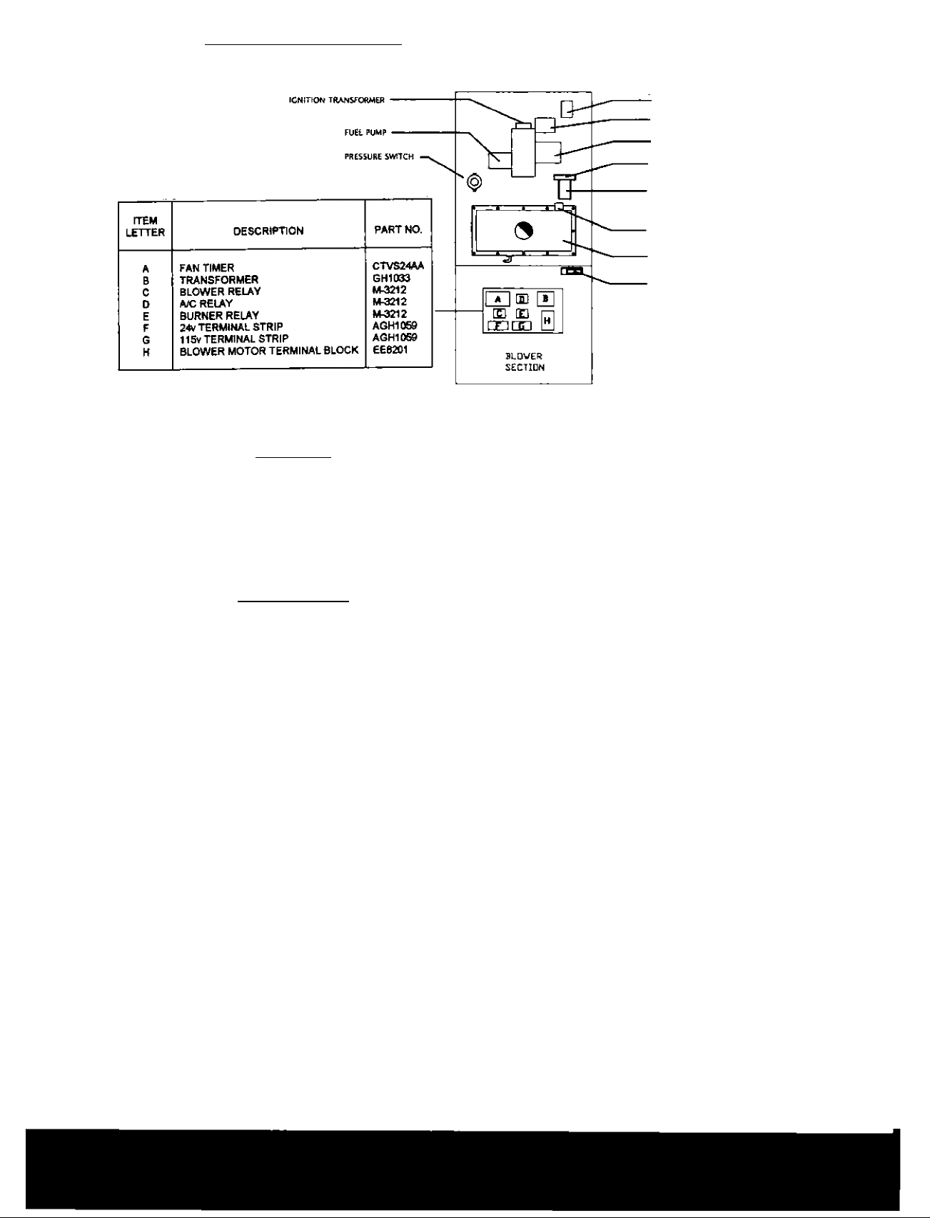
1. Component Identification
II. SAFETY
Please adhere to the following
warnings and cautions when
installing, adjusting, altering,
servicing, or operating the furnace.
Important
The following In^Fumerrts must be used to
adjust the burner on startup.
Fatture to use the proper tn^niments will void
our warranty and will result in an
luisatisfactory Installation.
Bacharach Electronic Combustion Analyzer
Bacharach Smoke Tester
(Or equivalent to above)
Oil Pressure Gauge
WARNING
TO PREVENT PERSONAL INJURY OR
DEATH DUE TO IMPROPER
INSTALLATION, ADJUSTMENT,
ALTERATION, SERVICE OR
MAINTENANCE, REFER TO THIS
MANUAL. FOR ADDITIONAL
ASSISTANCE OR INFORMATION,
CONSULT A QUALIFIED INSTALLER,
SERVICE AGENCY OR THE FUEL OIL
SUPPLIER.
HIG H LIM IT
> faRIMARY OIL CONTROL
' aURNER MOTOR
■ fUEL FILTER HEAD
FUEL FllTER CARTWOCE
auxiliary ÜMET
MANUAL RESET
CONDENSATE COLLECTOR
BLOWER DOOR
INTERLOCK SWTCH
Figure 1
WARNING
HIGH VOLTAGEI
TO AVOID PROPERTY DAMAGE,
PERSONAL INJURY OR DEATH DUE TO
ELECTRICAL SHOCK, THE FURNACE
MUST BE LOCATED TO PROTECT THE
ELECTRICAL COMPONENTS FROM
WATER.
WARNING
DO NOT UTILIZE THE HEATING UNIT
WITHOUT REASONABLE ROUTINE
INSPECTION, M/UHTENANCE AND
SUPERVISION. IF THE UNIT IS IN A
BUILDING THAT IS OR WILL BE
VACANT, CARE SHOULD BE TAKEN TO
ROUTINELY INSPECT, MAINTAIN AND
MONFTOR THE UNIT. IN THE EVENT
THAT THE BUILDING MAY BE EXPOSED
TO FREEZING TEMPERATURES AND
WILL BE VACANT, DRAIN ALL WATER
BEARING PIPES, PROPERLY WINTERIZE
THE BUILDING AND TURN OFF ALL
WATER SOURCES. IN THE EVENT THAT
THE BUILDING IS EXPOSED TO
FREEZING TEMERATURES AND IS
VACANT, ANY HYDRONIC COIL UNITS
SHOULD ALSO BE DRAINED AND AN
ALTERNATIVE HEAT SOURCE UTILIZED.
Page 4

TRANSPORTATION DAMAGE
WARNING
WE WILL NOT BE RESPONSIBLE FOR
ANY INJURY OR PROPERTY DAMAGE
ARISING FROM IMPROPER SERVICE OR
SERVICE PROCEDURES. IF YOU
INSTALL OR PERFORM SERVICE ON
THIS UNIT, YOU ASSUME
RESPONSIBILLITY FOR ANY PERSONAL
INJURY OR PROPERTY DAMAGE WHICH
MAY RESULT. MANY JURISDICTIONS
REQUIRE A LICENSE TO INSTALL OR
SERVICE HEATING AND AIR
CONDITIONING EQUIPMENT.
INSTALLATION AND SERVICE MUST BE
PERFORMED BY A QUALIFIED
INSTALLER, SERVICE AGENCY OR
FUEL OIL DEALER.
DANGER
PELIGRO
CARBON MONOXIDE
POISONING HAZARD
All units are securely packed in shipping
containers tested according to International
SafeTransit Association specifications.
The carton must be checked upon arrival for
external damage. If damage is found, a
request for inspection by carrier’s agent
must be made in writing immediately.
1. Make a notation on delivery receipt
of any visible damage to shipment
or container.
2. Notify carrier promptly and request
an inspection.
3. With concealed damage, carrier
must be notified as soon as possible
- preferably within five days.
4. File the daim with the following
support documents within a nine
month statute of limitations.
o Original or certified copy of
the Bill of Lading, or
indemnity bond,
o Original paid freight bill or
indemnity in lieu thereof,
o Original or certified copy of
the invoice, showing trade
and other discounts or
reductions.
o Copy of the inspection
report issued by carrier's
representative at the time
damage is reported to
carrier.
To The Installer
Before installing this unit, please read this
manual thoroughly to familiarize yourself
with specific items which must be adhered
to, including, but not limited to; unit
maximum external static pressure, oil
pressure, BTU input rating, proper electrical
connections, circulating air temperature rise,
minimum or maximum CFM, and motor
speed connections. ’
The carrier is responsible for making
prompt inspection of damage and for a
thorough investigation of each claim. The
distributor or manufacturer will not accept
claims frcxn dealers for transportation
damage.
Keep this literature In a safe place for
future reference.
Page 5

III. PRODUCT APPLICATION
This furnace is primarily designed for
residential home-heating applications. It is
NOT designed or certified for use in mobile
home, trailers or recreational vehicles. This
unit is NOT designed or certified for outdoor
applications. The furnace must be installed
indoors (i.e., attic space, crawl space, or
garage area provided the garage area is
enclosed with an operating door).
This furnace can be used in the foliowring
non-industrial commercial applications;
Schools, Office buildings, Churches,
Retail stores. Nursing homes,
Hotels/motels, common or office areas
In such applications, the furnace must be
installed with the following stipulations;
o It must be installed per the
installation instructions provided and
per local and national codes.
o it must be installed indoors in a
building constructed on site.
o It m ust be part of a ducted system
and not us^ in a free air delivery
application.
o It must not be used as a “make-up"
air unit.
o This furnace may NOT be used as a
construction site heater.
To ensure proper installation and operation,
thoroughly read this manual for specifics
pertaining the installation and application of
this product.
_________________________________
I
WARNING
Possible property damage, personal
injury or death due to Are, explosion,
smoke, soot, condensation, etectrical
shock or carbon monoxide may result
from improper installation, repair,
operation or maintenance of this product
INSTALLATION CODES
INSTALLATION MUST COMPLY WITH
THE REQUIREMENTS OF AUTHORITIES
HAVING JURISDICTION.
All local and national codes governing the
installation of oil burning equipment, wiring,
and venting must be followed. Some of the
applicable codes are:
CAN/CSA B139 Installation Code for Oil
Burning Equipment.
NFPA 31 Installation Code for oil Burning
Equipment
ANSI/NFPA SOB Warm Air Heating and Air
Conditioning Systems.
ANSI/NFPA 70 National Etectrical Code.
CSAC22.1 Canadian Electrical Code.
ANSI/NFPA 211 Chimneys, Fireplaces,
Vents and Solid Fuel Burning Appliances.
A copy of the CAN/CSA B139 Installation
Codes can be obtained from;
CSA International
178 Rexdale Boulevard
Etobicoke, Ontario, Canada MdWIRS
or
CSA International
8501 East Pleasant Valley
Cleveland, OH 44131
The rated heating capacity of the furnace
should be greater than or equal to the total
heat loss of the area to be heated. The total
heat loss should be calculated by an
approved method or in accordance with
"ASHRAE Guide" or “Manual J-Load
Calculations” published by the Air
Conditioning Contractors of America.
WARNING
To prevent personal injury, property
damage or death due to fire, do not
install this furnace in a mobile home,
trailer or recreational vehicle.
To ensure proper furnace operation, install,
operate and maintain the furnace in
accordance with these installation and
operation instructions, ail local building
codes and ordinances.
IV. LOCATION REQUIREMENTS &
CONSIDERATIONS
GENERAL
WARNING
TO PREVENT POSSIBLE EQUIPMENT
DAMAGE, PROPERTY DAMAGE.
PERSONAL INJURY OR DEATH, THE
FOLLOWING BULLET POINTS MUST BE
OBSERVED WHEN INSTALLING THE
UNIT.
Page 6

Follow the instructions listed below when
selecting a furnace location.
Refer also to the guidelines provided in
Section V. Combustion and Ventilation
Air Requirements.
о Centrally locate the furnace with
respect to the proposed or existing
air distribution system.
о Ensure the temperature of the return
air entering the furnace is between
55 F and 90 F when the furnace is
heating.
о Provide provisions for venting
combustion products outdoors
through a proper venting system.
Special consideration should be
given to ventfflue pipe routing and
combustion air intake pipe when
applicable. Refer to Section IX,
Vent/Flue Pipe and Combustion Air
Pipe Termination Locations for
appropriate termination locations
and to determine if the piping
system from furnace to termination
can be accomplished within the
guidelines given.
о NOTE: The length of flue and/or
cc^bustion air piping can be a
limiting factor in the location of the
furnace.
Exposure to contaminated combustion air
will result in safety and performance related
problems. Do not install the furnace where
the combustion air is exposed to the
following substances;
Chlorinated waxes or deaners
Chlorine-based swimming pool chemicals
Water softening chem icals
Deicing salts or chemicals
Carbon tetrachloride
Halogen type refrigerants
Cleaning solutions (such as
perchloroethylene
Printing inks
Paint removers
Vanishes
Hydrochloric acid
Cements and glues
Antistatic fabric softeners for clothes
dryers.
Masonry acid washing materials
o Seal off a non-direct vent furnace if
it is installed near an area
frequently contaminated by any of
the above substances. This
protects the non-direct vent
furnace from airborne
contaminants. To ensure that the
enclosed non-direct vent furnace
has an adequate supply of
combustion air, vent from a nearby
uncontamjnated room or from
outdoors. Refer to the Section V.
combustion and Ventilation Air
Requirements for details.
о Locate the furnace so condensate
flows downwards to the drain. Do
not locate the furnace or its
condensate drainage system in any
area subject to below freezing
temperatures without proper freeze
protection. Refer to Section X.
Condensate Drain Lines and Trap
for further details.
о Ensure adequate combustion air is
available for the furnace. Improper
or insuffícient combustion air can
expose building occupants to
combustion products that could
include carbon monoxide. Refer to
Section V., Combustion and
Ventilation Air Requirements.
о Set the furnace on a level floor to
enable proper condensate drainage.
If the floor becomes wet or damp at
times, place the furnace above the
floor on a concrete base sized
approximately 1-1/2 times larger
than the base of the furnace.
o If the furnace is used in connection
with a cooling unit, install the
furnace upstream or in parallel with
a cooling unit. Premature heat
exchanger failure wilt result if the
cooling unit is placed ahead of the
furnace.
o If the furnace is installed in a
residential garage, position the
furnace so that the burner and
ignition source are located not less
than 18 inches (457 mm) above
the floor. Protect the furnace from
physical damage by vehides.
Clearances and Accessibility
Installations must adhere to the
clearances to combustible materials to
which this furnace has been design
certified. The minimum clearance
information for this furnace is provided
on the units rating label.
Page 7

These clearances must be permanently
maintained. Clearances must also
accommodate an installation’s oil, electrical,
and drain trap and drain line connections. If
the alternate vent/flue connections are used
additional clearance must be provided to
accommodate these condifions Section IX,
Vent Flue Pipe and Combustion Air Pipe for
details.
Appliances that pull air out of the house
(exhaust fans, fireplaces, clothes dryers,
etc.) increase the problem by starving
appliances for air.
House depressurization can cause back
drafting or improper ccxnbustion of oil fired
appliances, thereby exposing building
occupants to combustion products that
could include carbon monoxide and cause:
NOTE: In addition to the required
clearances to combustible materials, a
minimum of 24 inches service clearance
must be available in front of the unit.
A clearance of 24 inches at the rear of the
unit is also recommended.
Thermostat Location
The thermostat should be placed
approximately five feet from the floor on a
vibration-free, inside wall In an area having
good air circulation. Do not install the
thermostat where it may be influenced by
any of the following:
o Drafts or dead spots behind doors,
in corners, or under cabinets,
o Hot or cold air from registers,
o Radiant heat from the sun.
o Light fixtures or other appliances,
o Radiant heat from a fireplace,
o Concealed hot or cold water pipes,
or chimneys.
o Unconditioned areas behind the
thermostat, such as an outside
wall.
V. COMBUSTION & VENTILATION AIR REQUIREMENTS
! WARNING
TO AVOID PROPERTY DAMAGE,
PERSONAL INJURY OR DEATH,
SUFFICIEWT FRESH AIR FOR PROPER
COMBUSTION AND VENTILATION OF
FLUE GASES MUST BE SUPPLIED.
MOST HOMES REQUIRE OUTSIDE AIR
BE SUPPLIED INTO THE FURNACE
AREA.
Improved construction and additional
insulation in buildings have reduced heat
loss by reducing air infiltration and escape
around doors and windows. These changes
have helped in reducing heating/cooling
costs, but have created a problem supplying
combustion and ventilation air for burning
appliances.
1. Nausea-Headaches-Dizziness, Flu
Like symptoms.
2. Excessive humidity - heavily frosted
windows or a moist feeling in the
home,
3. Smoke from a fireplace will not draw
up the chimney.
4. Flue gases that will not draw up the
appliance vent pipe.
Combustion and Ventilation Air
Adequate provisions for combustion air,
ventilation of furnace, and dilution of the
gases must be made. When a furnace is
installed in an unconfined space in a
building, it can be assumed that infiltration
will be suffident to supply the required air.
If the furnace is installed in a confined space
and combustion air is taken from the heated
space, the supply air and ventilating air must
be through two permanent openings of
equal area. A confined space is "a space
whose volume is less than SO cubic feet per
1000 BTU per hour of the combined input
rating of all appliances installed in that
space." One opening must be within 12" of
the ceiling and the other within 12" of the
floor. Each opening must have a minimum
free area of at least 1 square inch per 1000
BTU per hour of total input rating of all
appliances within the space but not less
than 100 square inches.
if the furnace is installed in a space within a
building of tight construction and air must be
supplied from outdoors. In this case, one
opening shall be within 12” of the ceiling and
the other within 12" of the floor.
If vertical combustion ducts are run, each
opening must have a free area of at least 1
square inch per 4000 BTU per hour.
If horizontal combustion ducts are run, 1
square inch per 2000 BTU per hour of the
total input of all appliances Is required.
Page 8

A return air duct system is reccxnmended.
Where there is no complete return air duct
system, a return connection should be run
full size to a location outside the confined
space and completely sealed so that no air
from the confined space can be circulated
through the heating duct system.
EXISTING FURNACE REMOVAL
NOTE: When an existing furnace is
removed from a venting system serving
other appliances, the venting system may be
too large to properly vent the remaining
attached appliances.
If this furnace is to be installed in the same
space with other oil fired appliances, such
as a water heater, ensure there is an
adequate supply of combustion and
ventilation air for the other appliances.
VI. VENT/FLUE PIPE &
COMBUSTION AIR PIPE
! WARNING
FAILURE TO FOLLOW THESE
INSTRUCTIONS CAN RESULT IN BODILY
INJURY OR DEATH. CAREFULLY READ
AND FOLLOW ALL INSTRUCTIONS
GIVEN IN THIS SECTION.
I
WARNING
UPON COMPLETION OF THE
FURNACE INSTALLATION,
CAREFULLY INSPECT THE
ENTIRE FLUE SYSTEM BOTH
INSIDE AND OUTSIDE OF THE
FURNACE TO ASSURE IT IS
PROPERLY SEALED. LEAKS IN
THE FLUE SYSTEM CAN RESULT
IN SERIOUS PERSONAL INJURY
OR DEATH DUE TO EXPOSURE
TO FLUE PRODUCTS. INCLUDING
CARBON MONOXIDE.
A condensing oil furnace achieves its high
level of efficiency by extracting almost all of
the heat from the products of combustion
and cooling them to the point where
condensation takes place. Because of the
relatively low flue gas temperature and
water condensation requirements, PVC pipe
is used as venting material. This furnace
must not be connected to Type B. BW, or L
vent or vent connector, and must not be
vented into any portion of a factory built or
masonry chimney, except when used as a
pathway for PVC as descried later in this
section. Never common vent this appliance
with another appliance or use a vent which
is used by a solid fuel appliance.
Do not use commercially available "no hub
connector" other than those shipped with
this product.
It is the responsibility of the installer to follow
the manufacturers’ recommendations and to
verify that all vent/flue piping and connectors
are compatible with furnace tiue products.
Additionally, it is the responsibility of the
installer to ensure that all piping and
connections possess adequate structural
integrity and support to prevent flue pipe
separation, shifting, or sagging during
furnace operation.
MATERIALS AND JOINING METHODS
WARNING
TO AVOID BODILY INJURY, FIRE OR
EXPOLSION, SOLVENT CEMENTS MUST
BE KEPT AWAY FROM ALL IGNITION
SOURCES (I.E., SPARKS, OPEN FLAMES
AND EXCESSIVE HEAT) AS THEY ARE
COMBUSTIBLE LIQUIDS. AVOID
BREATHING CEMENT VAPORS OR
CONTACT WITH SKIN AND/OR EYES.
Three-inch nominal diameter PVC Schedule
40 pipe meeting ASTM D1785, PVC primer
meeting ASTM F6566, and PVC solvent
cement meeting ASTM D2564 specifications
must be used. Fittings must be DWV type
fittings meeting ASTM D2665 and ASTM
03311. Carefully follow the manufacturer’s
instructions for cutting, cleaning, and solvent
cementing of PVC,
As an alternative to PVC pipe, primer,
solvent cement, and fittings, ABS materials
which are in compliance with the following
specifications may be used. Three-inch
ABS Schedule 40 pipe must meet ASTM
D1527 and, if used in Canada, must be CSA
listed solvent cement for ABS to PVC
transition jdnt must meet ASTM D2235 and,
if used in Canada must be CSA listed. The
solvent cement for the PVC to ABS
transition joint must meet ASTM D3138.
Fittings must be DWV type fittings meeting
ASTM D 2661 and ASTM D3311 and, if
used in Canada, must be CSA listed.
Carefully follow the pipe manufacturers'
instructions for cutting, cleaning, and solvent
cementing PVC and/or ABS.
AH 90 elbows must be medium radius (1/4
bend DWV) or long radius (Long sweep >4
bend DWV) types conforming to ASTM
D3311, A medium radius (1/4 bend DWV)
elbow measures 4-9/16 minimum from the
plane of one opening to the centerline of the
other opening for 3" diameter pipe.
Page 9

PROPER VEWT/FLUE AND COMBUSTION
AIR PIPtNG PRACTICES
Adhere to these instructions to ensure safe
and proper furnace performance.
The length, diameter, and number of elbows
of the ventfflue pipe and combustion air pipe
effects the performance of the furnace and
must be carefully sized.
All piping must be installed In accordance
with local codes and these instructions.
Piping must be adequately secured and
supported to prohibit sagging, joint
separation, and/or detachment from the
furnace.
Horizontal runs of vent/flue piping must be
supported every three to five feet and must
maintain a % inch per foot downward slope,
back towards the furnace, to properly return
condensate to the furnace's drain system.
Precautions should be taken to prevent
condensate from freezing inside the
vent/flue pipe and/or at the vent/tiue pipe
termination.
TERMINATION LOCATIONS
EXHAUST VENT/INLET AIR
LOCATION
1. The vent piping for this furnace is
approved for zero clearance to
combustible construction.
2. The condensing oil furnace, like all
high efficiency products, is likely to
produce a visible vapor plume due
to condensation. Surfaces near the
vent termination will likely be coated
with condensation.
3. Care must be taken to locate the
exhaust vent where the exhaust
gas, vapor plume, and condensation
do not cause a hazard or nuisance.
For example, so not locate the
exhaust vent termination under a
deck where, under certain
conditions, it could form a coating of
ice causing a hazard or reduce the
life of the deck materials.
All vent/flue piping exposed to freezing
temperatures below 35 F for extended
periods of time must be insulated with %”
thick closed cell foam.
Also all vent/flue piping exposed outdoors in
excess of the terminations shown in this
manual (or in unheated areas) must be
Insulated with 14” thick closed cell foam,
inspect piping for leaks prior to installing
insulation.
Fitting Desoiption
Elbow, 90
Cleanout Tee
Elbow, 45
Vertical Vent Termination
Sidewall Vent Termination
Equivalent Length
5
5
3
0
0
Page 10

Sidewall Vent System
a) Sidewall vented products are
susceptible to wind conditions that can
effect combustion. To minimize the
effects of wind, exhaust and air inlet
terminations must penetrate the same
wall or vertical surface. In addition,
the length of the exhaust and air inlet
pipes must be roughly equivalent.
b) Condensation from a sidewall vented
appliance may cause paint and other
surface coatings to deteriorate. In
addition, soot stains may appear on
surrounding surfaces if the furnace is
not properly maintained.
c) See Figure 2 for an illustration of
clearances for location of exit
terminals for direct-vent, sidewall
venting systems.
d) The vent system shall terminate at
least 3 feet above any forced air inlet
located within 10 feet. NOTE: This
does not apply to the combustion air
inlet of 3 direct-vent appliance.
e) Provide a minimum of 1 foot distance
from any door, operable window, or
gravity air inlet into any building.
f) Do not locate the exhaust termination
directly under an operable window.
g) Provide a minimum of 1 foot clearance
from the bottom of the exhaust
termination above the expected snow
accumulation level. Snow removal
may be necessary to maintain
clearance.
h) Provide 4 feet horizontal clearance
from electrical meters, gas meters, air
conditioning condensers or other
external equipment. In no case shall
the exit terminal be above or below
the aforementioned equipment unless
a 4 foot horizontal distance is
maintained.
i) Do not locate the exit termination over
public walkways where condensate
could drip or freeze, causing a hazard
or nuisance. ,
i) When the exhaust termination is
adjacent to a public walkway, it is to
be located at least 7 feet above grade.
K) Do not locate exhaust termination
directly under roof overhangs to
prevent icicles from forming.
I) Provide 3 feet clearance frtxn the
inside corner of adjacent walls.
The vent termination of a non-direct vent
application must terminate at least 4 feet
below, 4 feet horizont^ly from, or 1 foot
above any door, window, or gravity air inlet
into any building.
FORCED AIR INÌ.ET
IZ' ABOVE
EXPECTED SNOW
ACCUMUUTION
Location of Exit Tomtlnols of Mochonical Draft and Diract-Vantlng Systoma
IF A' )S l£SS THAN 10 FT.
TFCN S' IS TO 8E 3 FT. MMUUU
OIL TANK
AIR VENT
DIRECT VENT
TERMINATION
Figure 2
9
Page 11

STANDARD FURNACE CONNECTIONS
It is the responsibility of the installer to
ensure that the piping connections to the
furnace are secure, airtight, and adequately
supported.
All furnaces are shipped with a combustion
air connection on the cabinet exterior and a
flue connector on the inside of the cabinet
on the condensate collector box.
VENT/FLUE PIPE
Vent/flue pipe can be secured to the
vent^ue coupling using the rubber coupling
and worm gear hose clamps provided with
this furnace (see “Standard connections"
figure). The rubber coupling allows
separation of the vent/flue pipe from the
furnace during servicing.
Combustion Air and Vent piping should be
routed in a manner to avoid contact with
refrigerant lines, metering devices,
condensate drain lines, etc. If necessary,
clearances may be increased by utilizing two
45 degree Long-Sweep Elbows and creating
an “S” joint to provide additional space at
connection locations. This joint can be
rotated on the fitting to establish maximum
clearance between refrigerant lines,
metering devices, and condensate drain
lines, etc. This joint is the equivalent of one
90 degree elbow when considering elbow
count.
NOTE: Do not use other commercially
available “no hub connectors" due to
possible material conflicts. Theventfflue
pipe can also be secured usirrg a PVC or
ABS elbow or coupling using the appropriate
glue (see Section VI, Materials and Joining
Methods).
\^NT/FLUE AND COMBUSTION AIR PIPE
LENGTHS
Refer to the following table for applicable
length, elbows, and pipe diameter for
construction of the vent/flue and combustion
air intake pipe systems of a direct vent (dual
pipe) installation. The number of elbows
tabulated represents the number of elbows
and/or tees in each (Vent/Flue &
Combustion Air Intake) pipe. Elbows and/or
tees used in the terminations must be
included when determining the number of
elbows in the piping systems.
If the combustion air intake pipe is to be
installed above a finished ceiling or other
area wrfiere dripping of condensate will be
objectionable, insulation of the combustion
air pipe may be required. Use W thick
closed cell foam insulation such as Armaflex
or Insultube where required.
Non-Direct or Direct Vent (Dual Pipe)
Three (3) inch Pipe Diameter
Maximum Allowable Length of Vent/Flue and
Combustion Air Intake Pipe (ft)
Unit
input
BTU
Vent/fiue/Air
Intake Pipe
Termination
Maximum Allowable Length of
Vent/Flue Pipe (ft.)
Number of Elbowe
2 3 4 5 6 7 8
50.000
75.000
100.000
125.000
50.000
75.000
100.000
125,000
Standard 68 65 62
Alternate 55 52 49 46
59 56 53 50
Notes:
1.
Minimum requirement for each vent
pipe is five (5) feet in length and one
elbow/tee.
2.
Tee used in the vent/flue tennination
must be included when determining
the number of elbows in the piping
system,
3.
3" diameter
4.
Increased Clearance Configurations
using (2) 45 degree Long Sweep
elbows should be considered
equivalent to one 90 degree elbow.
Vent/Fiue atKl combustion Air Pit>e
Terminations
The vent/flue and combustion air pipes
may terminate vertically, as through a
roof, or horizontally, as through an
outside wail. Vertical pipe terminations
should be as shown in the following
figure. Refer to Section VI Vent/Flue
Pipe and Combustion Pipe Termination
Locations for details concerning location
restricfions. The penetrations through
the roof must be sealed tight with proper
flashing such as is used with a plastic
plumbing vent.
43 40
37
10
Page 12

Installations require both a vent/flue pipe and a
combustion air intake pipe. Refer to the
appropriate section for details concerning piping
size, length, number of elbows, furnace
connections, and terminations.
DIRECT VENT fPUAL P\PE\ PIPING BECKETT NX
NON-DIRECT VENT fPUAL PIPE^
INTERburner
Installations require both a combustion air intake
and a ventrue pipe. The pipes may be run
horizontally and exit through the ^de of the
building or run vertically and exit through the
roof of the building.
The pipes may be run through an existing
unused chimney; however, they must extend a
minimum of 12 inches above the top of the
chimney.
The space between the pipes and the chimney
must be closed with a weather tight, corrosion
resistant flashing. Both the combustion air
intake and vent/flue pipe terminations must be in
the same atmospheric pressure zone.
Horizontal terminations should be as shown in
the following figure. Refer to Section Vi,
Vent/Flue Pipe and Combustion Pipe -
Termination Location for location restrictions,
A 3 Î4 inch diameter hole is required for 3”
diameter pipe. To secure the pipe passing
through the wall and prohibit damage to piping
connections, a coupling should be installed on
either side of the wall and solvent cemented to a
pipe connecting the two couplings.
The pipe length should be the wall thickness
plus the depth of the socket fittings to be
installed on the inside and outside of the wall.
The wall penetration should be sealed with
silicone caulking material.
Refer to Section VI, Vent/flue and Combustion
air Pipe - Termination Locations or Concentric
Vent Termination for specific details on
termination construction.
For details concerning connection of pipes to the
furnace, refer to the Section VI, Vent/Flue Pipe
and Combustion Pipe - Standard Furnace
connections or alternate furnace connections.
ROOF VENT SYSTEM
The vent termination of vent pipe run vertically
through a roof must terminate at least 12 inches
above the roof line (or the anticipated snow
level) and be at least 12 inches from any vertical
wall (including any anticipated snow build up).
Standard horizontal Terminations (Dual Pipe)
Vertical Terminations (Dual Pipe)
Alternate Horizontal Vent Termination (Dual
Pipe)
11
Page 13

VII. ELECTRICAL CONNECTIONS
! WARNING
HIGH VOLTAGEI
To avoid the risk of electrical shock,
wiring to the unit must be polarized
and grounded.
! WARNING
HIGH VOLTAGEI
To avoid personal Injury or death due
to electrical shock, disconnect
electrical power before servicing or
changing any electrical wiring.
Use a separate fused branch electrical
circuit containing properly sized wire,
minimum 12 gauge, and fuse or circuit
breaker.
The furnace must be electrically grounded
in accordance with local codes or, in their
absence, with the latest edition of;
The National Electric Code, ANSI NFPA 70.
The fuse or circuit breaker must be sized in
accordance with the maximum over-current
protection specified on the unit rating plate.
An electrical disconnect must be provided
at the furnace location.
NOTE: Line polarity must be observed
when making field connections.
! WARNING
! CAUTION
Label all wires prior to
disconnection when servicing
controls. Wiring errors can
cause improper and dangerous
operation. Verify proper
operation after servicing.
wiring Harness
The wiring harness is an integral part of this
furnace. Field alteration to comply with
electrical codes should not be required.
Wires are color-coded for identification
purposes. Refer to the wiring diagram for
wire routings. If any of the original wire as
supplied with the furnace must be replaced,
it must be replaced with wiring material
having a temperature rating of at least 105
degrees C. Any replacement wring must be
copper conductor.
115 Volt Line Connections
Before proceeding with electrical
connections, ensure that the supply voltage,
frequency, and phase correspond to that
specified on the unit rating plate. Power
supply to the furnace must be N.E.C. Class
1, and must comply wth all applicable
codes, and/or The Canadian Electric Code
CSA C22.1.
THE DRAIN TRAP MUST VBE
MOUNTED ON THE OPPOSITE SIDE
OF THE UNIT FROM THE JUNCTION
BOX. THIS WILL REDUCE THE RISK
OF WATER REACHING THE JUNCTION
BOX IN THE EVENT OF A BLOCKED
DRAIN CONDITION.
Connect hot, neutral, and ground wires as
shown in the wiring diagram located on the
unit's blower door. Line polarity must be
observed when making field connections.
Line voltage connections can be made
through either the right or left side panel.
The furnace is shipped configured for a right
side electrical connection with the junction
box located inside the blower compartment.
To make electrical connections through the
opposite side of the furnace, the junction
box must be relocated to the other side of
the blower compartment prior to making
electrical connections.
NOTE: Wire routing must not interfere with
circulator blower operation, filter removal, or
routine maintenance.
! WARNING
EDGES OF SHEET METAL HOLES
MAY BE SHARP. USE GLOVES AS A
PRECAUTION WHEN REMOVING HOLE
PLUGS.
12
Page 14

^ CHEO ONLY
LIMIT
Relay #1 Burner Relay #2 Heating
Wiring Diagram
Relay #3 Cooling
Page 15

I
WARNING
HIGH VOLTAGE!
TO AVOID THE RISK OF INJURY,
ELECTRICAL SHOCK OR DEATH, THE
FURNACE MUST BE ELECTRICALLY
GROUNDED IN ACCORDANCE WITH
LOCAL CODES OR IN THEIR
ABSENCE, WITH THE LATEST
EDITION OF THE NATIONAL
ELECTRIC CODE.
To ensure proper unit grounding, the ground
wire should run from the furnace ground
screw located inside the furnace junction
box all the way back to the electrical panel.
NOTE: Do not use oil piping as an
electrical ground. To confirm proper unit
grounding, turn off the electrical power and
perform the following check:
1. Measure resistance between the
neutral (white) connection and a
suitable chassis ground.
2. Resistance should measure 10 ohms or
less.
This furnace is equipped with a blower door
interlock switch which interrupts unit voltage
when the blower door is opened for
servicing. Do not defeat this switch.
24 Volt Thermostat Wiring
NOTE: Wire routing must not interfere with
circulator blower operation, filter removal, or
routine maintenance.
Low voltage connections can be made
through either the right or left side panel.
Thermostat wiring entrance holes are
located adjacent to the junction box
locations in the blower compartment.
The condensate which is generated must
be piped to an appropriate drain location.
The furnace’s drain hoses may exit either
the right or left side of the furnace.
in horizontal installations, the drain hoses
will exit through the bottom (down side) of
the unit with the drain trap su^nded
beneath the furnace.
The field'Supplied drain system must be in
accordance with all local codes and the
instructions in the following sections.
Follow the instructions below when installing
the drain system.
Refer to the following sections for specific
details concerning furnace drain trap
installation and drain hose hook ups.
The drain trap supplied with the furnace
must be used.
DRAIN TRAP ASSEMBLY
Check for proper fit of the entire assembly
Before cementing the individual
components together. Place the flexible
pipe coupling on the sub protruding from the
90 degree elbow connected to the
condensate collector, then insert the 6 inch
pipe stub and tighten the clamps on each
end of the flexible coupling.
Attach the tee to the stub coming out of the
furnace and insert 10 inch stub to bottom of
the tee. Attach the trap assembly to the
bottom of the stub using PVC pipe coupling.
Do Not use pipe cement on the flexible
pipe coupling. Add water to the trap until
some runs out of the drain overflow. Do not
install the drain in areas subject to freezing.
DRAIN CONNECTION
Thermostat Diagram
This furnace is equipped with a 40 VA
transformer to facilitate use with most
cooling equipment. Consult the wiring
diagram, located on the blower
compartment door, for further details, of 115
Volt and 24 Volt wiring.
VIII. CONDENSATE DRAIN LINES
& DRAIN TRAP
GENERAL
A condensing oil-ftred furnace achieves its
high level of efficiency by extracting almost
all of the heat from the products of
combustion and cooling them to the point
where condensation takes place.
Insert the Yt inch ID tubing through the hole
in the cabinet and press on to the barb
fitting. Do not use excessive force
on the drain pan. Connect the other end to
the top 90 degree barb on the drain trap
assembly. Connect another piece of tubing
to the bottom of the tee on the drain trap
and run to the condensate neutralizer. The
condensate neutralizer must lay in a
horizontal position. Connect installer
furnished tubing (type UVT or equivalent,
Yt" ID) to the other end of the condensate
neutralizer and run to a drain. Do not install
the drain in areas subject to freezing.
14
Page 16

MAKE HOLE HERE
F0RC02 MLASUREME^fT,
SMOKE AND TEMPERATURE
READINGS
SEAL WITH RTVSIUCONE
APPROXIMATELV 18’ABOVE
CENTERLINE OF TEE
DO NOT USE CEMENT
AT METAL COLLAR
STAINLESS/RUBBER
QUICK CONNECT COUPLER
CONDENSATE COLLECTOR
VENT TO ATMOSHPERE
PREFILL TRAP WTH WATER
FLUE PRODUCTS
CONDENSATE NEUTRAUZER
NEUTRALIZER MUST LAY
HORIZONTALLY
REPLACE AT THE BEGINNING
Of EACH HEATING SEASON
TO FLOOR DRAIN
OR CONDENSATE PUMP /¿=
IX. OIL LINE
GENERAL
The furnace rating plate includes the approved
furnace input rating and fuel types. The furnace
must be equipped to operate on the type of oil
applied.
CAUTION I
TO PREVENT UNRELIABLE
OPERATION OR EQUIPMENT
DAMAGE, THE OIL LINE PRESSURE
MUST BE SET AT 140 P.S.I.
OIL TANK
Oil storage tanks must be selected and installed in
compliance with applicable codes; in the United
States, NFPA31.
Standard for the Installation of Oil Burning
Equipment. Chapter 2, and in Canada, CAN/CSAB139, Installation Code for Oil Burning Equipment.
Section 6. Observe all local codes and by-lays. In
general, the oil tank must be properly supported and
remain stable in both empty and full conditions. The
oil tank must be fitted with vent and supply pipes to
the outdoors. Refer to the above-mentioned codes
for sizing. The vent pipe must be no less than 1 %
inches I.P.S., and terminate with an appropriate vent
cap in a location where it will not be blocked.
Note:
Furnace
may be
vented from
left OF right
side.
■7
The fill pipe must be no less than 2 inches I.P.S..
and terminate with an appropriate cap In a location
where debris will not enter the fill pipe during oil
delivery.
If located indoors, the tank should normally be in the
lowest level, (cellar, basement, etc.), it must be
equipped with a shut-off valve at the tank outlet used
for the oil supply. The oil tank must be located as to
not block the furnace/room exit pathway. Observe
all clearances specified in the above-mentioned
codes.
PIPING INSTALLATION
In the United States, NFPA 31, Standard for the
Installation of Oil Burninq Equipment. Chapter 2.
In Canada, the entire fuel system should be installed
in accordance with the requirements of CAN/CSA
B139, and local regulations. Use only approved fuel
oil tanks, piping, fittings, and oil filters.
Ensure that all fittings used in a copper oil tine
system are high quality flare fittings. Do not use
compression fittinqs Do not use Teflon tape on any
fittings.
Pressurized or gravity feed installations must not
exceed 3 PSIG. Pressures greater than 10 PSIG
may cause damage to the shaft seal. If the height of
the oil stored in a tank above the oil burner exceeds
11 ^ feet, it may be necessary to use a pressure
regulating device approved for this purpose.
15
Page 17

The furnace may be installed with a one-pipe system
with gravity feed or lift. The maximum allowabie lift
on a single line system is 8 feet. Lift should be
measured from the bottom (outlet) of the tank, to the
inlet of the burner. Sizing a single fine system is
complex because of the difficulty estimating the
pressure drop through each fitting, bend and
component in the line. In general, keep single line
systems short as possible. Two-stage oil pumps are
available for either the INTERbumer or Beckett
burner.
The following chart shows the allowable line lengths
(horizontal & vertical) for single and two stage oil
pumps. All distances are in feet.
In retrofit applications, where an existing oil line
system is in place, a vacuum check will help
determine the integrity of the existing oil line system.
The vacuum in a system should not exceed 6" Hg.
For a single pipe system, not 12" Hg. For a two-pipe
system.
To eliminate air leakage, fuel line should be a
continuous length from tank to burner and flare
fittings must be used on all connections. On threaded
connections, use pipe dope that is resistant to fuel oil
(Rector seal #5, Permatex or equivalent). Do not use
PTFE Joint tape.
OIL LINES
Copper Tubing OH Line Lengths fFeett
Srngte-Pipe
Lift
Ft
0 53
1 49 100
2 45
3
4 37 100 58
5 33 100 55
6 29 100
7 25
8
g 17 68 45 100
10 13 52
12
14
16
18
3rö”
O.D
Tubing
41 100 60 100
21
— —
— —
— —
—
O.D
Tubing
100 68 100
100 63 100
99 SO 100
83
—
Two-Pipe
3/6'
O.D.
Tubing
65 100
53 100
48 100
42 100
37 100
32 100
27 100
22 88
'A‘
O.D.
Tubing
100
100
For additional information, see the installation
information sheet included in the documents envelope
or affixed to the oil burner and R.W. Beckett Bulletin
(664S0S)
Solvina After Diio and Locating Oil Line Leaks
Bulletin (664822).
NOTE: ^th the iNTERburner AND Beckett oil
burners require the use of a bypass plug when
converting from single-pipe to two-pipe oil piping
systems. See burner manufacturer’s instructions.
X. CIRCULATING AIR & FILTERS
Ductwork - Air Flow
Duct systems and register sizes must be properly
designed for the CFM and external static pressure
rating of the furnace. Design the ductwork in
accordance with the recommended methods of “Air
conditioning Contractors of America” Manual D.
install the duct system in accordance with Standards
of the National Board of Fire Underwriters for the
installation of Air Conditioning, Warm Air Heating and
Ventilating Systems. Pamphlets No. 90A and 90B.
A closed return duct system must be used, with the
return duct connected to the furnace.
NOTE: Ductwork must never be attached to the back
of the furnace.
Flexible joints may be used for supply and return
connections to reduce noise transmission. To prevent
the blower from interfering with combustion air or
draft when a central return is used, a connecting duct
must be installed between the unit and the utility room
wall. Never use a room, closet, or alcove as a return
air chamber.
No furnace wili operate or heat properly if the
duct work it is attached to Is not sized or installed
correctly. Warm air runs should have dampers
installed so that they can be balanced room to
room. Dampers should be adjusted to provide a
minimum of 0.20 and a maximum of 0.50 inches
water column external static pressure in the warm
air plenum.
Keep in mind that 95% of all burner
and pump problems are caused by
three factors:
Air leak in tite fuel line, improperly
sized fuel lines and dirty fuel.
16
Page 18

When the furnace is used in connection with
a cooling unit, the furnace should be
installed in parallel with or on the upstream
side of the cooling unit to avoid
condensation in the heating element. With
a parallel flow arrangement, the dampers or
other means used to control the flow of air
must be adequate to prevent chilled air from
entering the furnace and, if manually
operated, must be equipped with means to
prevent operation of either unit unless the
damper is in the full heat or coot position.
FILTERS - READ THIS SECTION BEFORE
INSTALLING THE RETURN AIR
DUCTWORK
A FILTER MUST BE USED WITH THIS
FURNACE. Discuss filter maintenance with
the building owner. Filters are shipped with
this furnace. Filters must comply with UL900
or CAN/ULCS111 standards.
If the furnace is installed without filters, the
warranty will be voided.
Inspect Fitter Frequently!
Replace 3 times each heating season.
XI. START-UP PROCEDURE &
ADJUSTMENT
Please read the procedures outlined below
and familiarize yourself with the appliance
sequence of operation before conducting
any tests or starting the appliance.
Note; A separate start-up form is attached
to the instailation instructions and must be
completed and returned to the
manufacturer for warranty registration
within 30 days of installation.
Check that furnace is instaiied level. This is
important since the secondary heat
exchanger is pitched at 3 degrees for proper
condensate drainage. Check with a
carpenters ievel and shim accordingly.
Verify that the fuel supply lines are leakfree. Inspect ait connections for air leaks.
Fuel system integrity is often assumed, but
cannot be overlooked. Test the fuel system
for integrity. Even a small leak can cause a
multitude of burner issues. Never use
compression fittings.
INTERburner Mark 10 or Beckett NX.
Check pump seal by shutting off pump and
noting the pressure drop. The pump
pressure should drop approximately 20%
and hold indefinitely.
Prime oil filter supplied with the appliance
before bleeding air from system. Purge the
oil pump of air in the system as soon as the
burner motor starts rotating by or>ening
bleeder valve on pump and catch oil in
suitable container.
Check post-purge timing on primary safety
controi by examining dip-switch
configuration on the primary control. This
controi is factory set at 8 minutes post purge
time.
Locate fan control in blower compartment.
Check blower-on time delay. Set delay for
30 seconds.
Verify blower-off delay setting at 390-600
seconds. This is required for proper heat
removal from the heat exchanger once the
thermostat is satisfied.
Do not remove blower deck support bracket
located in the blower compartment. This
bracket may be confused for a shipping
bracket and must not be removed. This
bracket is installed in up-flow and counter
flow models only. !t is a sheet metal
support bracket in the blower compartment.
Prime condensate drain trap with water.
Operate the burner for (3) minutes on, (3)
minutes off twice. Operate the burner for
approximately 30-40 minutes to cure the
internal ceramic fiber combustion
chamber. Be aware of moderate
odor/smoke upon initial firing and gradually
diminishing to nomnal over the break-in
period. Note the air handler should be
operating at all times during the break-in
period and final tuning.
You are now ready for the final fine-tuning.
The burner air settings are approximate
and needs to be adjusted to the vent system
in the fteld for most efficient operation.
Verify pump pressure with appropriate test
instrument. (140 PSI) for Adams
17
Page 19

Drill a 3/8” hole in the PVC exhaust vent piping
approximately 18" above where the PVC exits
the side of the furnace for your combustion
analysis equipment. (Seal with RTV silicone
when finished conducting combustion analysis).
BURNER
1) Operate burner for 15 minutes before
conducting test wortc.
2) Adjust burner settings until a trace (0-1 on
a smoke scale of 10) is obtained with smoke
test pump.
3) Read C02%. This should be
approximately 13.0%.
4) Increase air to burner to reduce C02% 1.0
to 1.5% less than where you were able to
obtain a trace of smoke.
77j/s procedure allows a margin of reserve for
variable conditions.
5) Re-check smoke to insure it is 0.
Your final C02% should be
approximately 11.5%
1.
Operate furnace with burner firing for
approximately ten minutes. Ensure all
registers are open and all duct dampers are
in their final (fully or partially open) position.
2.
Place thermometers in the return and supply
ducts as close to the furnace as possible.
Thermometers must not be influenced by
radiant heat by being able to "see" the heat
exchanger
HEAT EXCHANGER
RADIATION TJ NE OF SIGHT-
Check vent stack temperatures as beiow:
50
75
100
125
и
D
E
L
APPROX.
0
AMBIEtrr
PLUS
STACK
TEMP F.
20-24
27-31
29-33
38-42
INPUT
RATE
56,000
82,000
100,000
115,000
THERMAL
EFFICIENCY
97-99%
95-97%
94-96%
92-94%
Temperature Rise
Temperature rise must be within the range
below. An incorrect temperature rise may
result in condensing in or overheating of the
heat exchanger.
Detennine and adjust temperature rise as
follows:
Model
50-2.6 50-60
75-2.5
100-2.5 60-70
50-5
75-5
100-5
125-5 50-60
Temp. F.
Degree Rise
55-65
30-40
35-45
45-55
Temperature Rise Measurement
3.
Subtract the return air temperature from
the supply air temperature to determine the
air temperature rise. Allow adequate time
for thermometer readings to stabilize.
4.
Adjust temperature rise by adjusting the
circulator blower speed. Increase blower
speed to reduce temperature rise.
Decrease blower sp^ to increase
temperature rise.
Set thermostat heat anticipator setting at 0.2 A
as a base point. Operate furnace and measure
anticipation amperage and adjust thermostat to
manufacturer's instructions.
CIRCULATOR BLOWER SPEEDS
This furnace is equipped with a multi-speed
circulator blower. This blower provides ease in
adjusting blower speeds These blower speeds
should be adjusted by the installer to match the
installation requirements so as to provide the
correct heating temperature rise and correct
cooling CFM.
To adjust the circulator blower speed, proceed
as follows;
1. Turn OFF power to the furnace.
2.
Relocate desired motor leads to the
circulator blower terminals on the terminal
block as required.
Turn ON power to furnace.
3.
4.
Verify proper temperature rise as outlined in
Section XIV, Startup Procedure and
Adjustment - Temperature Rise.
18
Page 20

Circulator Blower Speeds
FAN ONLY MODE
Low Red
Medium Blue
Hiah Black
Common/Neutral White
XII. NORMAL SEQUENCE OF
OPERATION
POWER UP MODE
The normal power up sequence is as follows:
• 115 VAC power applied to furnace
• Furnace awaits call from thermostat
HEATING MODE
The normal operational sequence in heating
mode is as follows:
• R and W thermostat contacts close,
initiating a call for heat
Closure of the thermostat switch through relay
#1 energizes primary control on the burner.
Primary control goes in the pre-purge cycle,
runs for 15 seconds and then goes into ignition
sequence, burner ignites.
The normal operational sequence in fan only
mode is as follows:
• R and G thermostat contacts close, initiating
a call for fan
• Circulator blower is energized
• Circulator blower runs
• R and G thermostat contacts open,
completing the call for fan
• Circulator blower is de-energized
• Furnace awaits next call from thermostat
COOLING MODE
When the heat-cool switch is in the cool
position, and the thermostat calls for cooling, 24
volts AC at C and Y will complete the circuit to
contactor in condensing unit.
XIII. TROUBLESHOOTING
IMPORTANT:
DUE TO THE POTENTIAL HAZARD OF
LINE VOLTAGE, ONLY A TRAINED,
EXPERIENCED SERVICE TECHNICIAN
SHOULD PERFORM THE
TROUBLESHOOTING PROCEDURE.
Blower operation is controlled by Blower Delay
“On-Off’ Control Relay, mounted in control
panel face of blower.
With factory setting (DELAY ON MAKE) of (30
sec), approximately 30 seconds after burner
ignites, blower relay energizes to run comfort
blower in the heating speed mode.
THERMOSTAT SATISFIED
When the thermostat satisfied, heat contact
opens through relay No. 1, primary control relay
drops out, which de-energizes the primary
control. Burner goes into post-purge cycle, and
then shuts off. With factory setting (DELAY ON
BREAK) of 600 seconds, comfort blower
continues to run for approximately 390-600
seconds after burner is satisfied.
PRELIMINARY STEPS:
Check the diagnostic light for Indications of
burner condition. Refer to R7184 LED
Diagnostic Light section for details.
CAUTION !
When simulating a call for heat at the
R7184, disconnect at least one
thermostat lead wire from the T - T/3
terminals to prevent damage to the
themnostat. Neglecting this procedure
may burn out the heat anticipator of a
standard 24 VAC thermostat, or cause
harm to components of a micro
electronic themnostat.
19
Page 21

Table 1 System and General Troubleshooting
PROBLEM
Funwc« will not start
Fumac« will not start
wfttmut first pustilng oil
prfcnary confab reset
button.
(Occurs ttequently)
POSSIBLE CAUSE
Thermostat not calling for heat.
No power to furnace.
Thermostat faulty. Remove thermostat wires from the oil primary control terminal T-T. Put a jumper
on primary corrtrol faulty.
Cad ceH wiring shorted or room light
leaking into cad cell compartment.
Open safety switch
No Fuel oil СГюск fuel oil supply. Check that ak hand operated fuel oil valves are In the open
Clogged nozzle.
Clogged oil filter. Replace oil tank tiller or in-line fitter if used.
Low oil pump pressure. Connect pressure gauge to oil pump. Adjust pump pressure, or replace ok pump if
Air getting into hiet oil tines, or fuel oil
line dirty, dogged, or In some
manner defedive.
Check thenrrastat and adjust. Be sure it Is accurate. If it Is mercury type be sure It
kk leuel
Check furnace switch and main electrical parrel furnace fuse or circuit breaker.
acroes T-T. if furrtace starts, replace thermostat, thermostat sub-base or both.
Check reset button on oil primary control. Remove thermostat wire from оИ primary
control terminal T1 -T2. Check for 24 v. across T-T. If mo voltege is present, check
tor 115
V.
to oil primary. If 115v. is present go t о primary control diagrwstics.
Check cad ceil wiiir^ for short circuits. Check for room light leaking Into cad ceil
compartment.. Repair light leak if necessary.
Check for open high Umit, auxiliary limit, pressure or door Irrterlock swttch.
роаШоп. FIN oil storage tank if necessary.
Replace nozzle with high quality reptacement. Use rating plate or Tables to
Appendix A as a guide.
necessary. Ensure that erratic pressure readings are not caused by defective fuel
oil line.
Check fuel ok lines. Replace any compression fittings found with high quality flared
fittings. Check for any signs of oil leaks. Any oli leak is a potential source of air or
contaminants.
REMEDY
Furnace starts, but
shuts off requiring
manually res^rtg the
primary control reset
button.
Defective burner mctor.
Cad cell is dirty or defective
No fuel oil. Chedt fuel ok supply. Chedr that dl hand c^terated fuel di valves are to the c^ien
Clogged nozzle.
Clogged oU filter. Replace dl tank ruter or in-ltoe filter if used.
Low oil pump pressure. Connect pressure gauge to dl pump. Adjust pump pressure, or replace dl pump if
Air getting Into fuel oil lines, or fuel oil
line dirty, clogged, or in some
manner defective.
Defective burner motor.
Water or contamlnaiits in ok. Drain fuel di storage tank «к1 replace tool di. (Consult with fuel dl supplier).
Frozen oil line. Gently warm dl kne. Insulate dl line. (Outdoor piping size may require Increased
Check burner motor. If bunrer motor is cutting out on over-toad, determine why.
Replace If necessary.
If cad cell Is dirty, dean It. (D^ermlne why cad cell» getting dirty). If cad cell is
poorly aimed, realign it. NOTE: The photocell should have a resistance of 100K
ohtTB in absence of light, a rrMwmum of ISOOohms in the presence of lightEneure that room light Is not leaking into the ced cell compartment. (See diagnostic
l№ section).
poeitton. Fill ok storage tank if necessary.
Replace nozzle with high quality replacement. Use rating plate or Tades in
Appendix A as a guide.
necessary. Ensure that erratic pressure readings are not caused by defective fuel
oil line.
Check fuel dl lines. Replace any compression fittings found with high quality flared
fittings. Checkforany signs ofok lealre. Any oil leak is a potential source of air or
contaminants.
Check burner rrwtor. If burner rrxitor Is cutting out on over-load, determine why.
Replace if necessary.
diameter).
20
Page 22

Table 1 System and General Troubleshooting
PROBLEM
OH burner
sputtering el
noctle
Ctieck stack
temperature.
POSSIBLE CAUSE
Etectrodes out of adjustment or defective.
Poor transformer high voitage connections
or defective transkmner.
Fuel oil Nter clogged.
Defechve oil pump.
Fuel oil line parttalty clogged or contains
air.
System temperature rise too high. 'Refer to start up procedure for correct temperature rise. Check for clogged air filters.
Poor fan ofT delay timing selection, {№
stops too soon) Fan control timer.
Fuel oil leak.
Stack temperature too high.
Thermostat Improperly adjusted or in poor
location.
Check electrode settings. Check electrodes for dirt bulkt4ip or cracks in porcelain.
Check contacts between the Igniter and electrodes. If OK, replace the igniter.
Replace fuel oil storage tank filter and/or fuel oil in-line filter.
Check burner motor/fuel dl pump coupling. Check oil pump pressure. Replace fuel oil
pump If necessary.
Bleed air from oil line.
If proMeiTi persists, replace oil Him.
Check blower fan for excess dirt build-up or debrts. Speed up blower fan if necessary.
Check ofT delay timing setting for a delay off between 390 and 600 seconds.
Check fuel on line for leaks. Repair or replace if necessary.
Check stack temperature. Stadr températures will normally range from 20-42 degrees
^xwe ambient.
Check thermostat heat anticipator setting agdnst measured amperage draw. Increase
heat anticipator setting If necessary. If the thermostat is being influenced by drafts,
sunlighi, ductwork, etc., relocate to more suitable location.
REMEDY
Morettian (0)
smoke
Soot bulk) up on
the Mast tube
(end coning).
Furnace will not
warm home to
desired
temperature.
Insufficient combustion air at oil burner
Heat otchanger partially blocked Chedc for soot build up in turbulators of secondary heat exchanger
Poor alignment of between oil burner blast
tube and fire pot.
Flame impingement caused by incorrect
nozzte araie. Check noQle sia and »xHe. Check distance from head to inside surtace of the fire pot.
Defective fire pot.
Airflow blocked or dirty air filter. Clean or replace air filter.
Thermostat adjustments or location.
Insufficient airflow.
Defective high limit corrtrol. Test high limit funcfion of all limit switches. Use a duct thermometer to assess accuracy
Under-sized nozzle. Check nozzle. If problem is not caused by air flow problems, use larger nczzle, If
Adjust oil burner combustion air to gain the highest C02 or lowest (Hectical 02 content
In the flue gas (see Burner Set Up).
Chedt alignment. Blast tube should be centered with fire pot burner opening. Oilburrter
head should be У* Inch back frari the inside surface of the fire pot.
Check fire pot. Repair or replace.
Check thermostat heat anticipator setting against measured amperage draw. Increase
heat anticipator setting if necessary. If the thermostat is beir^ Influenced by drafts,
sunlight, duct work, etc., rekx^e to more suitable kx;aUon.
Check ай dampers. Opencloseddampers Including registers In unused rooms. Check
system temperature rise. Iftemperature rise is too high, speed up blowerfan.
of limit control. Check for obstructions to airflow around limit switch bj-metal elements.
Replace control if necessary. NOTE: A. high limit Is auto-resd. B. Auxiliary limit Is
manual re^.
petmMed by rating Plate.
Blower ^n motor stopping intermittently
on overload
Burner motor stopping Intermittently on
overload.
Check blower fan motor amperage draw. Check motor ventiiation ports, clean if
necessary. Replace motor if necessary.
Check burner motor. R^ilace if necessary
21
Page 23

Table 1 System and General Troubleshooting
PROBLEM POSSIBLE CAUSE
Homs does not
heat evenly.
Supply air
temperature too
hot.
Supply air
temperature too
cool.
Supply air
tempwature too
cool during first
moments of
furnace cyde.
Improper distribution of heat.
Airflow Uocked or dirty air filter. Clean or replace air fitter.
Insufficient airflow.
Excess airflow.
Excessive duct losses. Check supply air ductwork. Sealleaky Joints and seams. Insulate ductwork if
Fan control "fiin on' setting too k3W,
Excessive duct losses.
This is unlikety to be a furnace i^'drlem. Balarx» duct system with dampers.
Check all dampers. Open closed dampers including registers in unused rooms. Check
system temoereture rise. Iftemperature rise is too high, spaed uo blower fen.
Check system temperature rise. Slow down blower fen is necessary.
necessarvincrrase fan on’fime. Register air deflectors may help.
Check supply air ductwork. Seal leaky joints and seams, (nsulata ductwork Ef
r>eces8ary.
XIV. Maintenance & Annual Inspection
1) Replace Delevan nozzle with exact capacity, angle and pattern as supplied.
REMEDY
2) Replace vestibule mounted oil filter with AF-1 filter.
3) Replace condensate neutralizer with part number CCR-1.
4) Remove air handler assembly (slide out) and inspect the bottom (upflow configuration) of the
secondary heat exchanger. Loosen accumulated foreign matter with soft brush and vacuum
clean.
5) Perform all routine safety switch function checks.
6) Perform combustion analysis as described on page 18 Burner Adjustment.
7) Do not remove rear access panel of heat exchanger. Internal cleaning of the primary or
secondary heat exchangers are not required (unless satisfactory combustion analysis
cannot be achieved).
! CAUTION
The ceramic combustion chamber located in the primary heat exchanger should not be handled
once it is cured at startup. Structural damage will occur, if handled and if broken the furnace will be
rendered inoperative.
NOTE:
If the secondary heat exchanger turbulators have a light coating of soot, this is normal and will not
affect the efficiency of the furnace.
22
Page 24

XV.
REPAIR & REPLACEMENT PARTS
Page 25

Furnace Assembly Drawing
 Loading...