

Page 1
Adam Equipment
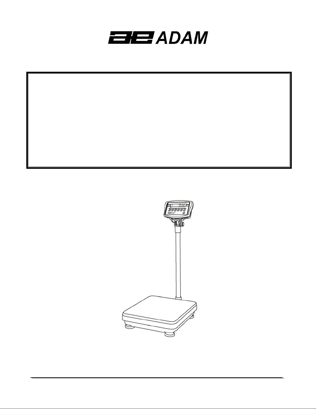
CFW SERIES
(P.N. 6162, Revision A5, May 2006)
Software Version: V1.04
@Adam Equipment Company 2006
Page 2

@Adam Equipment Company 2006
Page 3

CONTENTS
1.0 INTRODUCTION............................................................................................................3
2.0 SPECIFICATIONS.........................................................................................................4
3.0 INSTALLATION..............................................................................................................6
3.1 LOCATING THE SCALES..........................................................................................6
3.2 LIST OF ACCESSORIES...........................................................................................6
3.3 SETTING UP THE SCALES.......................................................................................7
4.0 KEY DESCRIPTIONS....................................................................................................8
5.0 DISPLAYS .....................................................................................................................9
6.0 OPERATION................................................................................................................10
6.1 ZEROING THE DISPLAY.........................................................................................10
6.2 TARING....................................................................................................................10
6.3 WEIGHING A SAMPLE............................................................................................11
6.4 PARTS COUNTING .................................................................................................11
6.5 CHECK-WEIGHING.................................................................................................13
6.5 ACCUMULATED TOTAL ..........................................................................................14
7.0 USER PARAMETERS .................................................................................................16
8.0 BATTERY OPERATION ..............................................................................................19
9.0 RS-232 INTERFACE....................................................................................................20
9.1 INPUT COMMANDS FORMAT ................................................................................21
10.0 CALIBRATION.............................................................................................................22
11.0 SERVICE SECTION ....................................................................................................23
11.1 CFW FACTORY PROGRAMMING AND CALIBRATIONS .......................................23
12.0 ERROR CODES ..........................................................................................................26
13.0 REPLACEMENT PARTS AND ACCESSORIES..........................................................27
14.0 SERVICE INFORMATION...........................................................................................27
@Adam Equipment Company 2006
1
Page 4

@Adam Equipment Company 2006
2
Page 5
1.0 INTRODUCTION
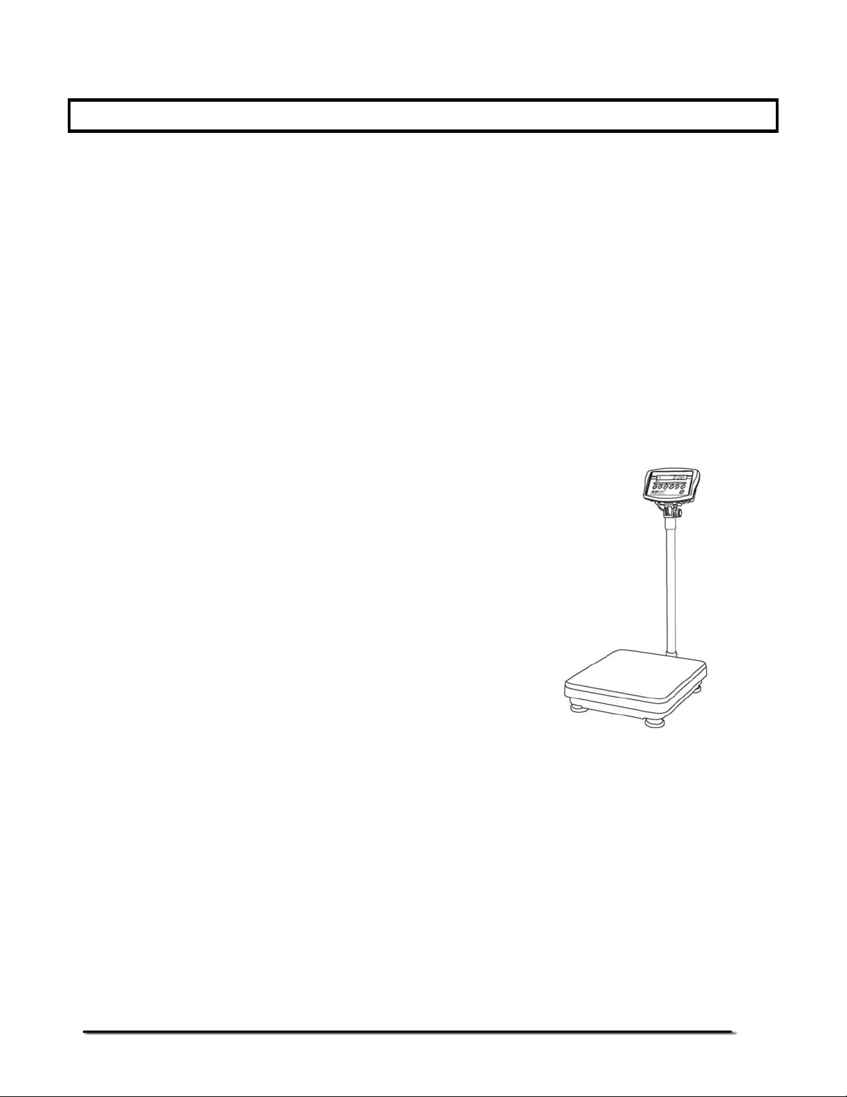
• The CFW series of scales provide an accurate, fast, versatile series of
general purpose weighing scales with counting and check-weighing
functions.
• There are 2 series of scales- CFW scales are kilogram only scales and
the CFWa scales offer changeable unit from pounds to kilograms. The
scales share the same functions but special instructions will be given
for the CFWa series to be able to change the weighing units.
• There are 4 models in each series with the maximum capacities up to
600 kg /1320 lb.
• They all have stainless steel weighing
platforms on a Steel base assembly and
a display module mounted on a pillar
attached to the base.
• All the keypads are sealed and have
colour coded membrane switches.
• The displays are large easy to read liquid
crystal type displays (LCD). The LCD’s
are supplied with a backlight.
• All units include automatic zero tracking, audible alarm for pre-set
weights, automatic tare and an accumulation facility that allows the
individual weights to be stored and recalled as an accumulated total.
• The scales have an optional bi-directional RS-232 interface for
communicating with a PC or printer.
@Adam Equipment Company 2006
3
Page 6
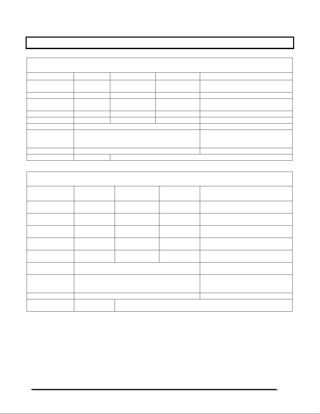
2.0 SPECIFICATIONS
CFW SERIES
Model # CFW 60 CFW 150 CFW 300 CFW 600
Maximum
Capacity
Readability 5 g 10 g 20 g 50g
Repeatability (Std
Dev)
Linearity ± 10 g 20 g 40 g 100g
Tare Range -60 kg -150 kg -300 kg -600kg
Platform Size 425 mm x 525 mm 600 mm x 800 mm
Overall
Dimensions
(w x d x h)
Net Weight 15 kg 45 kg
Units of Measure kg, g kg
60 kg 150 kg 300 kg 600kg
5 g 10 g 20 g 50g
425 mm x 700 mm x 950 mm 600 mm x 925 mm x 970 mm
CFWa SERIES
Model # CFW 130a CFW 330a CFW 660a
Maximum
Capacity
Readability 0.01 lb/
Repeatability (Std
Dev)
Linearity ± 0.02 lb/
Tare Range -130 lb/
Platform Size 16.7" x 20.7" /
Overall
Dimensions
(w x d x h)
Net Weight 33 lb / 15 kg 99 lb / 45 kg
Units of Measure Lb / oz / kg / g
130 lb/
60 kg
5 g
0.01 lb/
5 g
10 g
-60 kg
/ lb:oz
330 lb/
150 kg
0.02 lb/
10 g
0.02 lb/
10 g
0.04 lb/
20 g
-330 lb/
-150 kg
425mm x 525mm
425mm x 700mm x 950mm /
16.7" x 27.6" x 37.4"
660 lb/
300 kg
0.05 lb/
20 g
0.05 lb/
20 g
0.10 lb/
40 g
-660 lb/
-300 kg
600mm x 925mm x 970mm /
Lb / oz / kg / lb:oz
CFW 1320a
1320 lb/
600 kg
0.1 lb/
50 g
0.1 lb/
50 g
0.2 lb/
100 g
-1000 lb/
-600kg
23.6" x 31.5" /
600mm x 800mm
23.6" x 36.4" x 38.2"
@Adam Equipment Company 2006
4
Page 7
Common Specifications
Interface RS-232 bi-directional Interface (Optional)
Stabilisation Time 2 seconds typical
Operating Temperature 0°C - 40°C
32°F - 104°F
Power supply 9 VDC, 800 mA from external power supply
Internal re-chargeable battery (up to 70 hours operation)
Calibration Automatic External
Display 1 x 6 digits LCD digital display
Balance Housing Indicator: ABS Plastic
Top pan: Stainless Steel
Base: Cast Aluminium for all models except Mild Steel
for CFW 600 (CFW 1320a)
Applications General Purpose Floor Weighing Scales
Functions Weighing, Parts counting, Memory Accumulation,
Pre-set weighing with alarm
@Adam Equipment Company 2006
5
Page 8
3.0 INSTALLATION
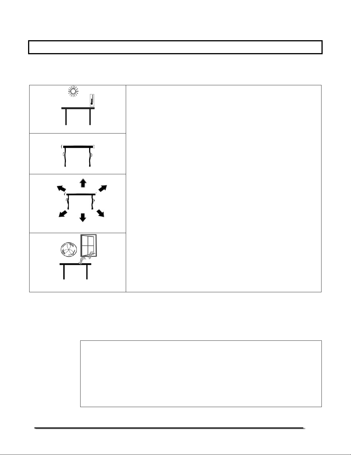
3.1 LOCATING THE SCALES
• The scales should not be placed in a location that
will reduce the accuracy.
• Avoid extremes of temperature. Do not place in
direct sunlight or near air conditioning vents.
• Avoid unsuitable tables. The table or floor must be
rigid and not vibrate.
• Avoid unstable power sources. Do not use near
large users of electricity such as welding
equipment or large motors.
• Do not place near vibrating machinery.
• Avoid high humidity that might cause
condensation. Avoid direct contact with water. Do
not spray or immerse the scales in water.
• Avoid air movement such as from fans or opening
doors. Do not place near open windows or airconditioning vents.
• Keep the scales clean. Do not stack material on
the scales when they are not in use.
3.2 LIST OF ACCESSORIES
Your packet contains-
9 AC adapter
9 Indicator
9 Metal base
9 Stainless Steel pan
9 Tubular pillar with top flanges
9 Bottom Bracket
9 4 Bolts and 2 set screws
9 Instruction manual
@Adam Equipment Company 2006
6
Page 9

3.3 SETTING UP THE SCALES
• The pillar is attached to the base using a bracket that must be
attached to the base frame first using the 4 bolts supplied. The pillar
is secured to the bracket using 2 sets of screws. The cable from the
base to the indicator module is run through the tube and taken out
through the plastic support at the top. Excess cable can be stored
within the tube.
• The CFW Series comes with a stainless steel platform packed
separately. Place the platform in the base.
• Level the scale by adjusting the four feet. If the scale rocks re-adjust
the feet.
• Attach the indicator module to the pillar by sliding it over the bracket
with the flanges engaged in the groves on the base. Attach the
cable from the base to the connector on the rear of the indicator.
• Attach the power supply module to the connector on the side of the
indicator. Press the [On/Off] key. The software revision number will
be displayed followed by a self-test showing all digits before the zero
is displayed along with the unit of weight that was selected last.
@Adam Equipment Company 2006
7
Page 10
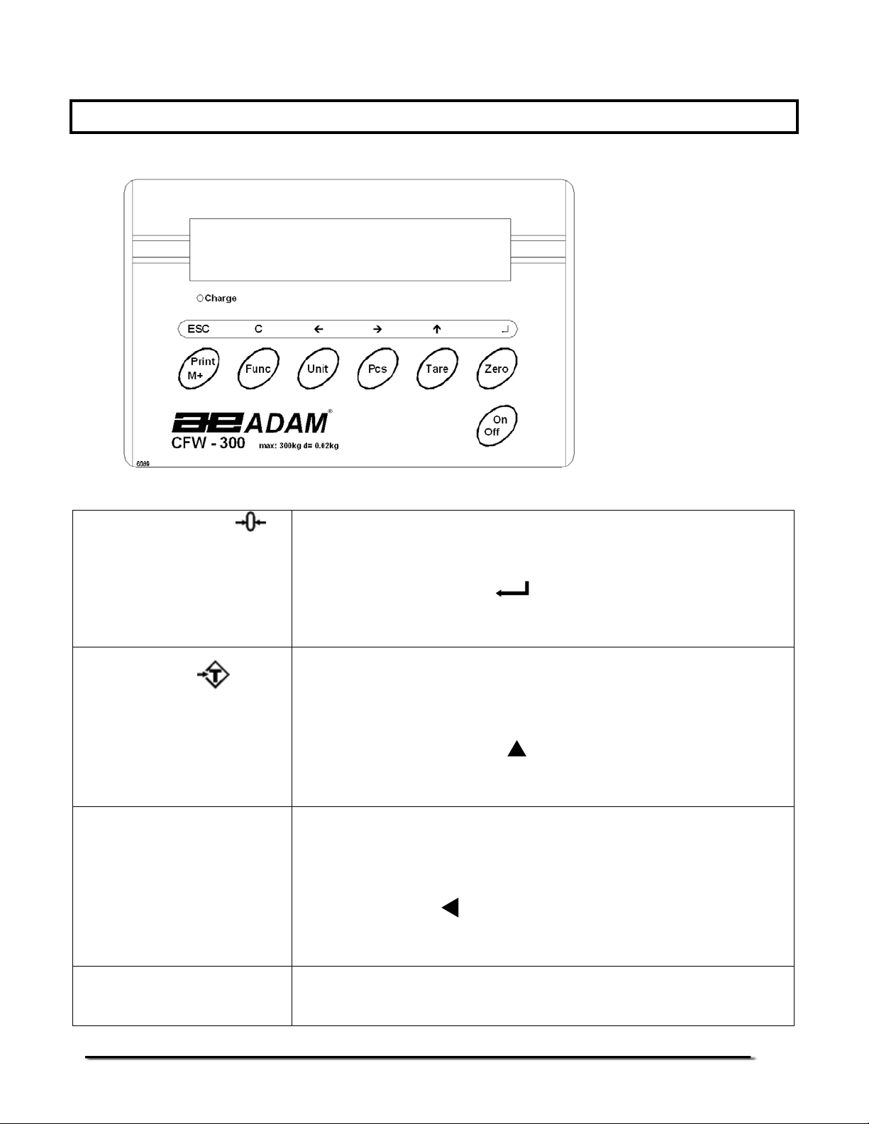
4.0 KEY DESCRIPTIONS
[Zero] or
[Tare] or
[Pcs]
[Unit] or [U]
Sets the zero point for all subsequent weighing. The
display shows zero.
A secondary function is of "Enter" key used when
setting up the value for the Parameters.
Tares the scale. Stores the weight currently on the
scale as tare value, subtracts the tare value from the
gross weight and shows the results.
A secondary function is of incrementing the active
digit when setting a value for Parameters.
Selects parts counting. Used to set the sample
quantities while parts counting.
A secondary function is to move the active/flashing
digit to the left when setting values for the
Parameters.
Selects the weighing unit to be displayed from those
which are enabled. See parameter F2 in section 7.
@Adam Equipment Company 2006
8
Page 11

[Func] or [F]
[Print/M+] or
[On] and [Off]
A secondary function is to move the active/flashing
digit to the right when setting values for the
Parameters.
Selects the Functions of the scale. If the scale is
weighing, it will select parts counting. If it is not in
weighing mode, it will return the user to weighing.
A secondary function (C) is to act as a clear key when
setting values for Parameters.
Sends the results to a PC or a Printer using the RS232 interface. It also adds the value to the
accumulation memory if the accumulation function is
not automatic.
A secondary function (ESC) is to return to normal
operation when the scale is in a Parameter setting
mode.
To switch on and switch off the indicator.
5.0 DISPLAYS
The LCD display will show a value and a unit to the right of the digits.
In addition there are labels for TARE, GROSS weight, ZERO, Stable
and for Low battery
@Adam Equipment Company 2006
9
Page 12

6.0 OPERATION
6.1 ZEROING THE DISPLAY
• You can press the [Zero/Enter] key at any time to set the zero point.
This will usually be necessary when the platform is empty. When the
zero point is obtained the display will show an indicator for zero.
• The scale has an automatic re-zeroing function to account for minor
drifting or accumulation of material on the platform. However you
may need to press the [Zero/Enter] key to rezero the scale if small
amounts of weight are shown when the platform is empty.
6.2 TARING
• Zero the scale by pressing the [Zero/Enter] key if necessary. The
“ZERO
• Place a container on the platform, a value for its weight will be
displayed.
• Press the [Tare/Ï] key to tare the scale. The weight that was
displayed is stored as the tare value and that value is subtracted
from the display, leaving zero on the display. The "GROSS" indicator
will be OFF and "TARE" indicator will be ON. As a product is added
only the net weight of the product will be shown. The scale could be
” indicator will be ON.
@Adam Equipment Company 2006
10
Page 13

tared a second time if another type of product was to be added to
the first one. Again only the weight that is added after taring will be
displayed.
• When the container is removed a negative value will be shown. If the
scale was tared just before removing the container this value is the
gross weight of the container plus all products that was removed.
The “ZERO
” indicator will be on to indicate that the platform is back
to the same condition as it was when the [Zero/Enter] key was last
pressed.
• To delete a Tare value, press [Tare/Ï] when the pan is empty.
6.3 WEIGHING A SAMPLE
To determine the weight of a sample, first tare the empty container if it is to be
used and then place the sample in the container. The display will show the net
weight of the sample and the units of weight currently in use.
6.4 PARTS COUNTING
• Before starting, tare the weight of any container that may be used,
leaving the empty container on the scale. Place a known number of
samples in the container, if used. The number should match the
options for parts counting, i.e., 10, 20, 50, 100 or 200 pieces.
• When the scale is showing weight, pressing the [Pcs] key will start
the parts counting function.
• The scale will show "P 10" asking for a sample size of 10 parts.
Change the sample size to the desired quantity by pressing the
[Tare/Ï] key. It will cycle through the options: 10, 20, 50, 100, 200
and back to 10.
@Adam Equipment Company 2006
11
Page 14

• Press the [Zero/Enter] key again when the number matches the
number of parts used as the sample. As more weight is added the
display will show the number of parts (pcs).
• Pressing the [Pcs] key will display the unit weight (g/pcs), pressing it
second time will display the net weight (pcs and kg) and the third
time, it will be the count again (pcs).
• Press the [Func/C] key to return to normal weighing or to start
counting a different sample.
@Adam Equipment Company 2006
12
Page 15

6.5 CHECK-WEIGHING
Check-weighing is a procedure to cause an alarm to sound when the weight on
the scale meets or exceeds values stored in memory. The memory holds
values for a high and a low limit. Either or both can be used.
See PARAMETERS Section for the procedure. To set the limits, "F0 H-L" is used.
After limits have been set the Check-weighing function is enabled.
When a weight is placed on the scale the arrows will show if the weight is above
or below the limits and the beeper will sound as described below.
BOTH LIMITS SET The display will show OK and the beeper will sound when the
weight is between the limits.
LOW LIMIT SET HIGH LIMIT is set to zero
The display will show OK and the beeper will sound when the
weight is less than the Low Limit. Above the Low Limit the
display will show HIGH and the beeper will be off.
HIGH LIMIT SET LOW LIMIT is set to zero
The display will show LOW and the beeper will be off when the
weight is less than the High Limit. Above the High Limit the
display will show OK and the beeper will be on.
BOTH LIMITS SET.
LOW IS SET GREATER
THAN HIGH
The beeper will never sound and the display will show LOW if
the weight is less that the LOW limit, and HIGH if the weight is
greater than the Low Limit.
NOTE: Weight must be more than 20 scale divisions for checkweighing to
operate.
@Adam Equipment Company 2006
13
Page 16

Checkweighing facility can be set up during Weighing or Parts Counting by entering
values as Low or/and High Limits keyed in by the user. The limits are displayed in
kg or pcs respectively.
Checkweighing during Weighing
Checkweighing during Parts Counting
To disable the Check-Weighing function enter zero into both limits by pressing
the [Func/C] key when the current limits are shown then pressing [Zero/Enter]
to store the zero values.
6.5 ACCUMULATED TOTAL
• The scale can be set to accumulate manually by pressing the
[Print/M+] key. See the PARAMETER Section for details of setting
the Parameter "F5 PRT". The accumulation function is only available
when weighing. It is disabled during parts counting.
• The weight displayed will be stored in memory when the [Print/M+]
key is pressed and the weight is stable.
• The display will show "ACC 1" and then the total in memory for 2
seconds before returning to weighing. If the optional RS-232
interface is installed the weight can be output to a printer or PC.
@Adam Equipment Company 2006
14
Page 17

• Remove the weight, allowing the scale to return to zero and put a
second weight on. Press the [Print/M+] key, the display will show
"ACC 2", then the new total and finally the value of the second
weight.
• Continue until all weights have been added.
• To view the total in memory press the [Print/M+] key when there is
no weight on the scale. The display will show the number of entries
and the total. See also the PARAMETER Section and use the
Parameter "F1 TOL" to select to print or to clear the memory.
No. of accumulation of weights
Total weight for 3 accumulations
@Adam Equipment Company 2006
15
Page 18

7.0 USER PARAMETERS
• The scale has 7 User Parameters that can be set by the user. To set
these Parameters press the [Func] key. The display will show the
first parameter, "F0 H-L".
• Pressing the [Tare/Ï] will cycle through the other parameters.
• Pressing [Zero/Enter] will allow you to enter a parameter directly for
setting or further enter a sub-parameter. Press the [Print/Esc] key to
leave the parameter unchanged.
• For setting a new value for the parameter or a sub-parameter, first
enter the parameter or sub-parameter by pressing the [Zero/Enter]
key. Then use the [Pcs/Í] key or the [Units/Î ] key to move the
active/flashing digit to the left or to the right and use the [Tare/Ï]
key to increment the flashing digit. Press the [Zero/Enter] key to
enter the changed value.
• Use the [Print/Esc] key to leave the parameter.
For example,
When the display shows “F0 H-L”, press the [Zero/Enter] key.
The display will show “SEt Lo” (the sub-parameter). Press
[Zero/Enter] to set the low limit or press the [Tare/Ï ] to skip to “SEt
Hi” for setting the high limit. When all digits have been set, press
[Zero/Enter] to store the value. Display will go back to the subparameter just set, i.e. “SEt Lo” or “SEt Hi”.
Press [Print/Esc] to return to “FO H-L”.
Advance to the next parameter (F1 toL) by pressing [Tare/Ï]
if
needed or press [Print/Esc] to return to weighing.
@Adam Equipment Company 2006
16
Page 19

SETTING OF USER PARAMETERS
PARAMETER SUB-
PARAMETER
SEt Lo
SEt HI
F1 toL
to CLr
to P-C
to Prt
F2 unt Ut oFF
Ut on
F3 tI
SEt dA
SEt tI
F4 oFF
CLoCK
DESCRIPTION DEFAULT
Sets a value for the Low Limit used for
checkweighing.
Sets a value for the High Limit for
checkweighing.
Clears the Accumulation Total in the
memory without printing the results.
Prints the Accumulation Total in the
memory and then clears the memory.
Prints the Accumulation Total in the
memory but does not clear the memory.
Enables or disables the weighing units.
Use the [Zero/Enter] key to select the
weighing unit to enable/disable. Use the
[Tare/Ï] to change the unit to ON or OFF.
Sets the date, Display will show the last
date set or 00.01.01. Enter the new date,
format is yy.mm.dd
Sets the time, Display will show the
current time Enter the new time, format is
hh.mm.ss
Sets clock to OFF or ON as screen saver.
CLK oF
VALUE
000.000 F0 H-L
000.000
CLK oF
bL
bEEP
CLK on
Sets the backlight to be on, automatic or
off
EL on
EL Au
EL oFF
Sets the beeper to-
1 (off all the time),
2 (ON when the weight is OK, i.e., in
between LO and HI limits) or
3 (ON only when the weight is outside the
limits during the check-weighing function).
This setting does not affect the beeper
during normal weighing.
EL Au
bP 2
@Adam Equipment Company 2006
17
Page 20

F5 Prt
ProG Pin
Sets the RS-232 -
P bAUd-Select from the desired baud
rates. Options are 600, 1200,
2400, 4800 and 9600
P nodE - Set the printing mode to-
P Prt (Print only when [Print] is
pressed)
P Cont (Print continuously)
P Auto (Print automatically
whenever there is any weight on
the scale).
Parity – Select from the following settings-
n 8 1 -8 data bits, no parity
E 7 1 -7 data bits, even parity
o 7 1 -7 data bits, odd parity
See the SERVICE SECTION for details.
4800
P Cont
n 8 1
• Use the [Print/Esc] key to leave the set-up mode of the parameter
and return to weighing.
@Adam Equipment Company 2006
18
Page 21

8.0 BATTERY OPERATION
• The scales can be operated from the battery if desired. The battery life
is approximately 70 hours.
• When the battery needs charging a symbol on the display will turn on.
The battery should be charged when the symbol is on. The scale will
still operate for about 10 hours after which it will automatically switch
off to protect the battery.
• To charge the battery, simply plug the adaptor into the mains power.
The scale does not need to be turned on.
• The battery should be charged for 12 hours for full capacity.
• Just under the display is an LED to indicate the status of battery
charging. When the scale is plugged into the mains power the internal
battery will be charged. If the LED is green the battery has a full
charge. If it is Red the battery is nearly discharged and yellow
indicates the battery is being charged.
@Adam Equipment Company 2006
19
Page 22

9.0 RS-232 INTERFACE
The CFW Series of scales can be ordered with an optional RS-232 bi-directional
interface.
Specifications:
RS-232 output of weighing data
ASCII code
4800 Baud (600-9600 selectable)
8 data bits (8 data bits no parity, 7 data bits even and odd parity selectable)
No Parity
Connector: 9 pin d-subminiature socket
Pin 2 Input
Pin 3 Output
Pin 5 Signal Ground
Data Format for normal weighing operations, parts counting or recalling of totals from
memory will all be different. Examples follow:
Normal Output:
No. 1 This number increments every time a new value is stored in
memory
GS 12.340kg GS for Gross weight, NT for net weight and a unit of weight
Total 12.340kg The total value stored in memory
<lf> Includes 2 line feeds
<lf>
@Adam Equipment Company 2006
20
Page 23

When parts counting- the weight, unit weight and count will be printed:
GS 12.340kg GS for Gross weight, NT for net weight and a unit of weight
UW 123.4g The average piece weight computed by the scale
PCS 100pcs The number of parts counted
<lf> Includes 2 line feeds
<lf>
When recalling the Total weight stored in the accumulation memory the output format
is:
*************** A line of stars is shown
TOTAL
No. 5
Wgt 21.455 kg .
***************
9.1 INPUT COMMANDS FORMAT
The scale can be controlled with the following commands. The commands must
be sent in upper case letters, i.e. “T” not “t”. Press the Enter key of the PC after
each command.
T<cr><lf>
Tares the scale to display the net weight. This is the same as pressing the [Tare] key.
Z<cr><If>
Sets the zero point for all subsequent weighing. The display shows zero.
T12.5<cr><if>
Same as entering a preset tare value of 12.5 from the keypad.
P<cr><lf>
Prints the results to a PC or printer using the optional RS-232 interface. It also adds the
value to the accumulation memory if the accumulation function is not set to automatic.
@Adam Equipment Company 2006
21
Page 24

10.0 CALIBRATION
The scale can be calibrated using the following procedure. For a more detailed
method of calibrating the scale, it will be necessary to enter the secure
Programming Menu. Refer to the CFW Service Manual for more information.
The CFW scales calibrate using either metric or pound weights, depending on
the weighing unit in use before calibration. The display will show either "kg" or
"lb" to identify the weights expected.
CFWa Scales only:
CFWa scales will also have the lb, oz, lb-oz or kg (or g) indicator on to show the unit of the
weight requested. If the scale was in pounds before starting the calibration, the weights
requested will be in pound values. If the scale was weighing in kilograms then metric weights
will be requested.
PROCEDURE
• Turn the power off.
• Turn the power back on, during the counting from 1 to 0, press [Func/C].
• The display will show "CAL ". While it is showing "CAL " press the [Unit],
[Print] and [Tare] keys in sequence to enter the Calibration section. The
display will show "unLoAd".
• Remove any weight from platform when stable and press [Zero/Enter].
• The display will show the last calibration weight used. If this is correct you
can continue by pressing [Zero/Enter]. If it is not correct use the arrow
keys to change the calibration weight value. When it is correct press
[Zero/Enter].
• The display will show "LoAd". Place the calibration weight on the scale.
Press the [Zero/Enter] key.
• If the calibration is acceptable the scale will run a self-test during which the
calibration weight should be removed. If an error message “FAiL L” is
shown try calibration again as a disturbance may have prevented a
successful calibration.
After calibration the scale should be checked for whether the calibration and
linearity is correct. If necessary repeat calibration, make sure that the scale is
stable before accepting any weight.
@Adam Equipment Company 2006
22
Page 25

11.0 SERVICE SECTION
To set the Service Parameters it will be necessary to enter the User Parameters
as before and then use a password code while entering the programming
parameter “PROG”.
11.1 CFW FACTORY PROGRAMMING AND CALIBRATIONS
• The parameter “PROG” allows access to the calibration section. To enter
this parameter press [Func] and then press [Tare/Ï] until "PROG" is
displayed.
• The Programming Parameter “PROG” has a number of sub-parameters that
allow the scale to be customised for the application. The “P1 rEF” sub-
parameter includes many functions that can affect the metrology of the
scale. These functions should not be reset to other values unless you
understand the affect it may have on the scale.
• Press [Zero/Enter] when “PROG” is displayed to show " PIn ", requesting for
the security password.
• Press the [Units], [Func] and [Print] keys in sequence to enter the
Programming/ Calibration menu. The display will show "P1 rEF". Press
[Zero/Enter] to set the functions of “P1 rEF”.
@Adam Equipment Company 2006
23
Page 26

SETTING OF SERVICE PARAMETERS
SUBPARAMETER
P1 rEF
FUNCTIONS DESCRIPTION DEFAULT
SETTING
AZn 0
0-Auto
0-rAnG
SPEEd
Auto Zero operating range.
(Options: 0.5d, 1.0d, 2d, 4d)
Sets the operational range of the auto
zero function.
Initial Zero range at power on.
(Options: 0%, 2%, 5%, 10% and 20%)
Sets the range for setting a zero when
power is applied. The total capacity of the
scale will not be affected by the new zero
if it is set within 10%. If it is set to a higher
value, the scale may zero but the range
may be limited by load cell, A/D converter
or mechanical stops within the base.
Zero range when [Zero] is pressed.
(Options: 4%,10%, 20%, 50%,100%)
Sets the range for setting a zero when
[Zero] is pressed. The total capacity of
the scale will not be affected by new zero
if it is set within 10%. If it is set to a higher
value, the scale may zero but the range
may be limited by load cell, A/D converter
or mechanical stops within the base.
Sets the display update speed.
(Options: 7.5, 15, 30 or 60).
1d
P1 10
(10%)
P2 10
(10%)
SPd 15
The P2 CAL sub-parameter has the basic functions used by the scale to set the
capacity, decimal point position, increment size as well as the calibration
procedures. Do not change the weighing functions as the scales may not
perform as specified. Either the capacity will be wrong, the decimal point will be
in the wrong position or the scale will increment with values that are not as
specified for the scales.
@Adam Equipment Company 2006
24
Page 27

P2 CAL
dEC1
InC
CAP
CAL
Selects the decimal point position
(Options: 0, 0.0, 0.00, 0.000).
Selects the increment size.
(Options: 1, 2, 5 and 10).
Sets the scale capacity. The maximum value
for the scale is as specified for the scale. For
example 60kg.
Starts the calibration procedure. See the
details of calibration procedure in section 10.
C 0.00
inC 10
The sub-parameter “P3 Pro” is used to view the calibration constant used by the
scale, view the A/D counts and set the scale back to default settings. This is
useful if it is not possible to have a good calibration of a scale. It will show the
load cell is causing the A/D to increment correctly through the complete range of
weights needed and you can recall the default settings for the scale. The “trl”
value can be modified to cause the scale calibration to change to a known
amount without the need for putting weights on the scale.
P3 Pro
trl
CoUnt
rESEt
Display will show a value that corresponds to
the load cell calibration. If the value is
increased the scale calibration will be
decreased a similar percentage.
Display will show the counts from the A/D
converter. The displayed count should
increase as the weight is added to the load
cell up to and exceeding the capacity of scale.
Typical range for these counts are:
No load 20,000
Maximum 120,000
Scale will reset to factory default settings.
Press [Zero/Enter] to continue or [Print/Esc]
to abort.
• Once the value is set, press [Print/Esc] to return to the sub-parameter.
• Pressing [Print/Esc] again will return the scale to normal weighing.
@Adam Equipment Company 2006
25
Page 28

12.0 ERROR CODES
ERROR
CODES
- -oL - -
Err 1
Err 2
Err 4
Err 6
FAIL H or
FAIL L
DESCRIPTION SUGGESTIONS
Over-range Remove weight from the scale.
Date Setting Error Enter date using correct format and reasonable values.
Time Setting Error Enter time using correct format and reasonable values.
Zero Setting Error The scale was outside the normal zero setting range either
A/D out of range The values from the A/D converter are outside the normal
Calibration error. Improper calibration (should be within + 10% of the factory
If the problem persists contact your dealer or Adam
Equipment for assistance.
Format: yy:mm:dd
Format: hh:mm:ss
when it was turned on or when the [Zero] key was pressed.
Remove weight from the scale and try re-zeroing again.
Use the [Tare] key to set the display to zero value.
If the problem persists contact your dealer or Adam
Equipment for assistance.
range.
Remove the weight from the scale if overloaded.
Make sure the pan is attached.
Indicates the load cell or the electronics may be faulty.
If the problem persists contact your dealer or Adam
Equipment for assistance.
calibration). The old calibration data will be retained until the
calibration process is complete.
If the problem persists contact your dealer or Adam
Equipment for assistance.
@Adam Equipment Company 2006
26
Page 29

13.0 REPLACEMENT P ARTS AND ACCESSORIES
If you need to order any spare parts and accessories, contact your supplier or Adam
Equipment. A partial list of such items is as follows-
• Power Supply Module
• Main Power cord
• Replacement Battery
• Stainless Steel Pan
• In use cover
• RS-232 option
• Printer, etc.
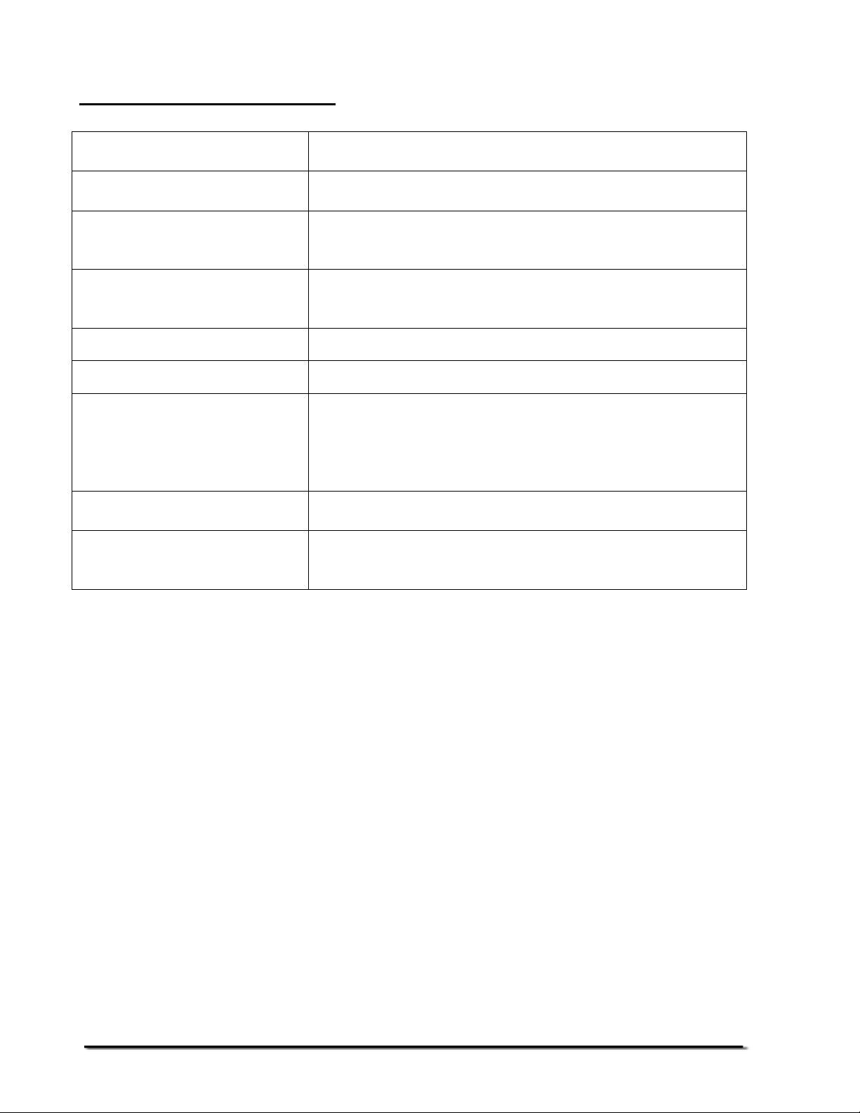
14.0 SERVICE INFORMATION
This manual covers the details of operation. If you have a problem with the scale that is not
directly addressed by this manual then contact your supplier for assistance. In order to provide
further assistance, the supplier will need the following information which should be kept ready:
A. Details of your company
-Name of your company:
-Contact person’s name:
-Contact telephone, e-mail,
fax or any other methods:
B.
Details of the unit purchased
(This part of information should always be available for any future correspondence.
We suggest you to fill in this form as soon as the unit is received and keep a printout in your record for ready reference.)
Model name of the scale:
Serial number of the unit:
Software revision number
(Displayed when power is first turned on):
Date of Purchase:
Name of the supplier and place:
C.
Brief description of the problem
Include any recent history of the unit. For example:
-Has it been working since it’s delivered
-Has it been in contact with water
-Damaged from a fire
-Electrical Storms in the area
-Dropped on the floor, etc.
@Adam Equipment Company 2006
27
Page 30

WARRANTY INFORMATION
Adam Equipment offers Limited Warranty (Parts and Labour) for the
components failed due to defects in materials or workmanship. Warranty
starts from the date of delivery.
During the warranty period, should any repairs be necessary, the purchaser
must inform its supplier or Adam Equipment Company. The company or its
authorised Technician reserves the right to repair or replace the
components at the purchaser’s site or any of its workshops depending on
the severity of the problems at no additional cost. However, any freight
involved in sending the faulty units or parts to the service centre should be
borne by the purchaser.
The warranty will cease to operate if the equipment is not returned in the
original packaging and with correct documentation for a claim to be
processed. All claims are at the sole discretion of Adam Equipment.
This warranty does not cover equipment where defects or poor performance
is due to misuse, accidental damage, exposure to radioactive or corrosive
materials, negligence, faulty installation, unauthorised modifications or
attempted repair or failure to observe the requirements and
recommendations as given in this User Manual.
Repairs carried out under the warranty does not extend the warranty period.
Components removed during the warranty repairs become the company
property.
The statutory right of the purchaser is not affected by this warranty. The
terms of this warranty is governed by the UK law. For complete details on
Warranty Information, see the terms and conditions of sale available on our
web-site.
@Adam Equipment Company 2006
28
Page 31

Manufacturer’s Declaration of Conformity
This product has been manufactured in accordance with the harmonised European standards,
following the provisions of the below stated directives:
Electro Magnetic Compatibility Directive 89/336/EEC
Low Voltage Directive 73/23/EEC
Adam Equipment Co. Ltd.
Bond Avenue
Denbigh East Estate
Milton Keynes, MK1 1SW
United Kingdom
FCC COMPLIANCE
This equipment has been tested and found to comply with the limits for a Class A digital
device, pursuant to Part 15 of the FCC Rules. These limits are designed to provide
reasonable protection against harmful interference when the equipment is operated in a
commercial environment. The equipment generates, uses, and can radiate radio frequency
energy and, if not installed and used in accordance with the instruction manual, may cause
harmful interference to radio communications. Operation of this equipment in a residential
area is likely to cause harmful interference in which case the user will be required to correct
the interference at his own expense.
Shielded interconnect cables must be employed with this equipment to insure compliance with
the pertinent RF emission limits governing this device.
Changes or modifications not expressly approved by Adam Equipment could void the user's
authority to operate the equipment.
@Adam Equipment Company 2006
Page 32

ADAM EQUIPMENT is an ISO 9001:2000 certified global organisation with more than 30
years experience in the production and sale of electronic weighing equipments. Products are
sold through a world wide distributor network -supported from our company locations in the
UK, USA, SOUTH AFRICA and CHINA. The company and their distributors offer a full range
of Technical Services such as on site and workshop repair, preventative maintenance and
calibration facilities.
ADAM’s products are predominantly designed for the Laboratory, Educational, Medical and
Industrial Segments. The product range can be classified as follows:
-Analytical and Precision Laboratory Balances
-Top Loading Scales for Educational establishments
-Counting Scales for Industrial and Warehouse applications
-Digital Weighing/Check-weighing Scales
-High performance Platform Scales with extensive software
features including parts counting, percent weighing etc.
-Crane scales for heavy-duty industrial weighing
-Digital Electronic Scales for Medical use
-Retail Scales for price computing
Adam Equipment Co. Ltd.
Bond Avenue
Milton Keynes
MK1 1SW
UK
Phone:+44 (0)1908 274545
Fax: +44 (0)1908 641339
e-mail:
sales@adamequipment.co.uk
Adam Equipment Inc.
26, Commerce Drive
Danbury, CT
06810
USA
Phone: +1 203 790 4774
Fax: +1 203 792 3406
e-mail:
sales@adamequipment.com
Adam Equipment S.A. (Pty) Ltd.
P.O. Box 1422
Kempton Park 1620
Johannesburg
Republic of South Africa
Phone +27 (0)11 974 9745
Fax: +27 (0)11 392 2587
e-mail:
sales@adamequipment.co.za
© Copyright by Adam Equipment Co. Ltd. All rights reserved. No part of this publication
may be reprinted or translated in any form or by any means without the prior permission of
Adam Equipment.
Adam Equipment reserves the right to make changes to the technology, features,
specifications and design of the equipment without notice.
All information contained within this publication was to the best of our knowledge timely,
complete and accurate when issued. However, we are not responsible for misimpressions
which may result form the reading of this material.
The latest version of this publication can be found on our Website.
Visit us at
@Adam Equipment Company 2006
www.adamequipment.com
 Loading...