

Page 1
Adam Equipment
AE-301 INDICATOR
P.N. 700660194 Revision B- November 2011
Software rev 2.4
© Adam Equipment Company November 2011
Page 2

© Adam Equipment Company November 2011
Page 3

CONTENTS
1.0 INTRODUCTION............................................................................................. 3
2.0 SPECIFICATIONS...........................................................................................3
2.1 KEYBOARD AND DISPLAY ........................................................................4
2.2 POWER SUPPLY........................................................................................5
2.3 LOAD CELLS...............................................................................................5
3.0 OPERATIONS................................................................................................. 6
3.1 POWER .......................................................................................................6
3.2 ZERO FUNCTION .......................................................................................6
3.3 TARE FUNCTION........................................................................................6
3.4 UNIT SELECTION....................................................................................... 6
3.5 WEIGHING ..................................................................................................7
3.6 CHECK WEIGHING.....................................................................................7
3.7 ALARM ........................................................................................................8
3.7.1 Over-load alarming ...............................................................................8
3.7.2 Low-load alarming ................................................................................8
3.7.3 Low battery alarming.............................................................................8
4.0 USER PARAMETERS.....................................................................................8
4.1 BLT = BACKLIGHT CONTROL ................................................................... 9
4.2 CHK = CHECKWEIGHING CONTROL........................................................9
4.3 FIL = FILTERING CONTROL ......................................................................9
4.4 SDT = RS-232 CONTROL.........................................................................10
4.5 PAR = SETTING OF PARITY.................................................................... 10
4.6 BPS = SELECTING BAUD RATE.............................................................. 10
5.0 RS-232 INTERFACE..................................................................................... 11
6.0 TECHNICAL PARAMETERS.........................................................................12
6.1 ZERO TRACKING .....................................................................................12
6.2 UNIT SETTING.......................................................................................... 12
6.3 CALIBRATION...........................................................................................13
7.0 TROUBLE-SHOOTING GUIDE.....................................................................14
8.0 SERVICE INFORMATION.............................................................................15
WARRANTY INFORMATION .................................................................................16
© Adam Equipment Company November 2011
1
Page 4

© Adam Equipment Company November 2011
2
Page 5
1.0 INTRODUCTION
The AE 301 Indicators are general purpose weighing indicators for use
cells. The AE 301 MD indicators come with a built-in load cell for
conversion of mechanical scale to digital readout by connection of the
load cell to the base assembly.
The indicators offer:
• Simple operation
• Zero Tracking
• Selectable automatic backlight
• Check-weighing with low and high limits
• RS-232 interface as standard
• Selectable communication mode
• Operation from internal rechargeable battery or mains power
• 4 weighing units (kg, g, ounce & pound)
2.0 SPECIFICATIONS
Model
Load cell capacity - 50 kg 100 kg
Internal Counting
resolution
Tare Range Full range
Units of Measure 4 (kg, g, lb, oz)
Stabilisation Time 2-3 seconds
Operating
Temperature
Interface RS-232 bi-directional
Power supply Re-chargeable battery located or mains power
AE 301 AE 301 MD-50 AE 301 MD-100
250,000
0°C to 40°C
Display Large LCD with backlight
Calibration Automatic calibration
Housing ABS Plastic
Dimensions
(w x d x h)
Net Weight 1.35 kg
© Adam Equipment Company November 2011
260 x 155 x 105 mm
3
Page 6
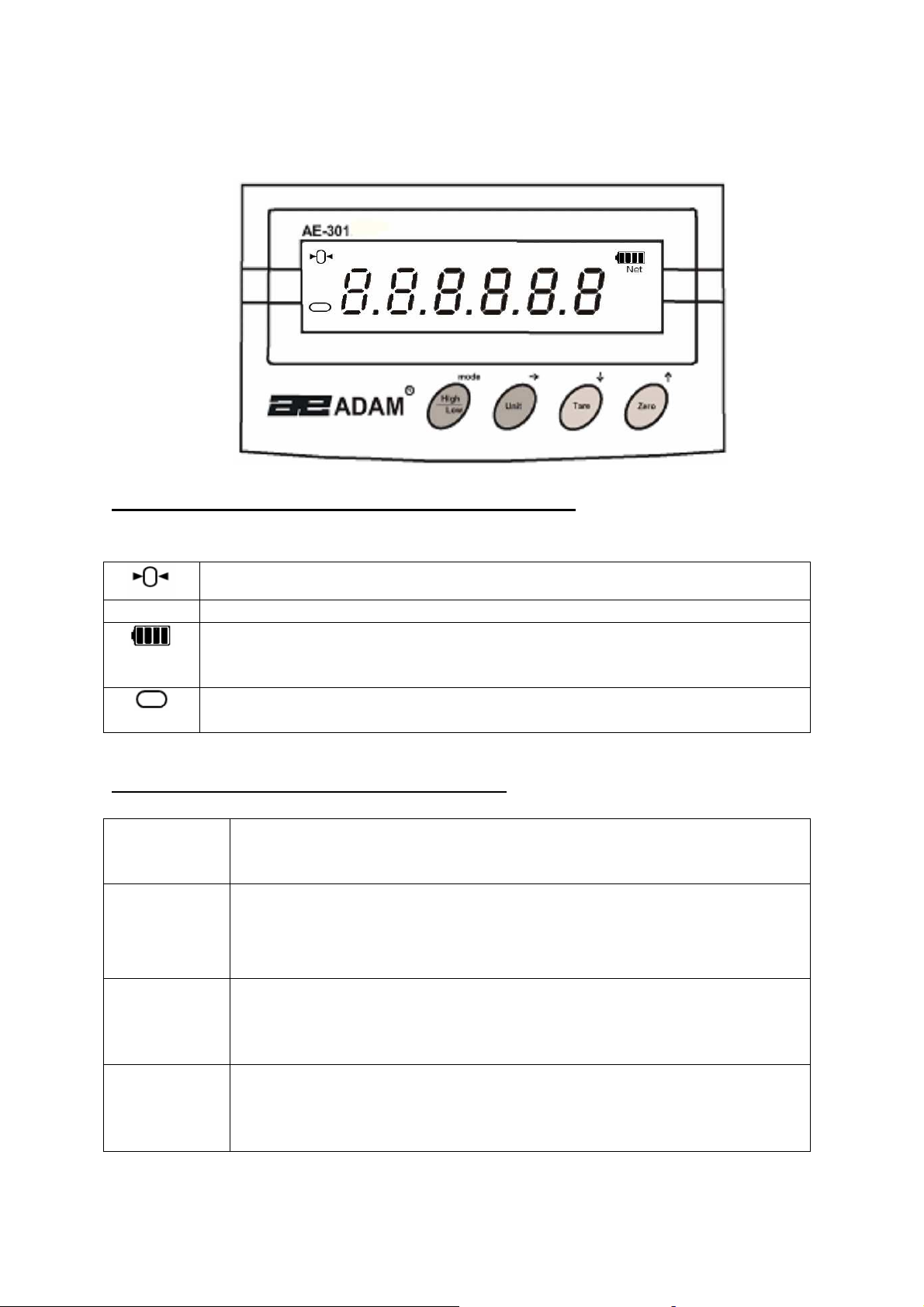
2.1 KEYBOARD AND DISPLAY
The AE-301 indicator has the following symbols:
The scale is at zero
Net A weight has been tared, the display is showing the net weight
The battery symbol showing the state of charge. While the battery is
being re-charged this symbol will show four bars
The weight is stable.
The keys perform the following functions:
[High/Low/
Mode]
[Unit/]
This key is used during setting of the user functions.
It is also used during setting of the High and Low Limits for checkweighing facility and for setting the alarm function.
This key is used to change the weighing units while the indicator is
in the weighing mode.
It is also used for advancing the digit while the indicator is in the
setting mode.
This key is used to deduct the weight of the container from the
[Tare/]
[Zero/ ]
© Adam Equipment Company November 2011
gross weight and thus to display the net weight only.
It is also used to decrease the digit while the scale is in the setting
mode.
This key is used to reset the zero position for accurate weighing
while the scale is in the weighing mode.
It is also used to the increment digit during the setting mode.
4
Page 7

2.2 POWER SUPPLY
• Power can be supplied using an internal re-chargeable
battery provided within the indicator case, or from mains
power.
•
If the battery is low on charge the symbol on the LCD will
show just one bar meaning the battery needs to be recharged immediately. While the battery is being re-charged,
this symbol will show four bars.
• With the internal re-chargeable acid battery, the battery life is
approximately 60 hours. The battery life will vary depending
on the use of the backlight
2.3 LOAD CELLS
• To connect the AE 301 indicator to a new base it is
necessary to connect the load cells properly. Then set the
parameters for the weighing system.
• User should ensure the load cells are correct for the purpose
and the signal from the load cell is correct.
• Note that it may not be possible to measure the voltage
signal from the load cell with all DVM. Some DVM will
measure the Excitation and signal voltage while others will
not. Try measuring the excitation voltage to determine if your
voltmeter will work.
CONNECTING TO LOAD CELLS
The AE 301 is supplied with a connector to connect an external
load cell.
The load cell can be connected in either a 4 or 6-wired
configuration. The standard connection is 4 wired.
Pin 1 Excitation +
Pin 2 Excitation –
Pin 3 Signal +
Pin 4 Signal –
© Adam Equipment Company November 2011
5
Page 8

3.0 OPERATIONS
3.1 POWER
• Attach the mains adaptor to the power supply and plug the
connector into the socket on the Indicator The indicator will
charge the internal battery whenever it is connected to the
220VAC power supply.
• Push the ON/OFF switch at the back right hand side of the
indicator to the ON position to power up.
• Push the ON/OFF switch at the back right hand side of the
indicator to the OFF position to power down.
3.2 ZERO FUNCTION
• For accurate weighing, zero the display by pressing the key
[Zero] with nothing on the platform of the scale.
• The zero indicator 0 will be on.
3.3 TARE FUNCTION
• When the scale has a container on it press the [Tare] key.
• The Tare indicator Net will be shown.
• The display will show zero. If it does not show zero, press
the [Zero] key.
• To clear the tare, remove the container and press the [Tare]
key again. Press [Zero] to switch off the Tare indicator.
3.4 UNIT SELECTION
• The indicator can be set for different units by pressing the
[Unit] key. The options are kilogram, gram, pound and
ounce. They can be enabled as needed (see section 6.2).
Kilogram is always on.
© Adam Equipment Company November 2011
6
Page 9

3.5 WEIGHING
• Place the sample on the scale platform. The weight will be
displayed in the selected Unit.
• Wait until the stable indicator is displayed for accurate
weighing.
3.6 CHECK WEIGHING
Check-weighing is a procedure to sound an alarm when the weight of
the sample on the scale meets or exceeds the pre-set Low and High
values stored in the memory.
To set the High and Low values, follow the procedure given below-
•
Press the [High/Low] key. The display will show “000.00 HI”
with the first digit flashing for setting the High value. To set
your limit, use the [Unit] key to advance the flashing digit, the
[Tare] key to decrease the value of the flashing digit and the
[Zero] key to increase the value of the flashing digit .
• The display will now show “000.00 LOW” with the first digit
flashing for setting the Low value. To set your limit, use the
[Unit] key to advance the flashing digit, the [Tare] key to
decrease the value of the flashing digit and the [Zero] key to
increase the value of the flashing digit . Press [Mode] again
to confirm the value and the display will return to normal
weighing mode.
• Once the check weighing Limits are set and the alarm
function is active, a beep will sound slowly when the sample
weight is below the Low Limit. The beep will sound quickly if
the weight is above the High Limit. If the sample weight is in
between the Limits, the beep does not sound.
© Adam Equipment Company November 2011
7
Page 10

3.7 ALARM
3.7.1 Over-load alarming
• When the sample weight on the scale is over the maximum
capacity the beep will sound and the display will show “Err“.
• Remove the weight immediately to avoid any damage to the scale.
3.7.2 Low-load alarming
• If the top pan is not placed on the scale the beep will sound.
• Place the top pan on the scale before starting to weigh.
3.7.3 Low battery alarming
• When appears on the LCD, re-charge the battery.
• During re-charging, the symbol will show four bars.
• If this symbol appears, re-charge the battery immediately to avoid
any damage to the battery.
4.0 USER PARAMETERS
The following parameters can be set by the user by entering the function
setting mode. Press the [Tare] key while switching on the indicator. The
first parameter will be displayed along with the settings done previously.
• The available parameters can be cycled through by pressing
the [Mode] key.
• Not all parameters may be enabled. Some parameters may
be set during the initial configuration and the user is not
given access to them. In this case those will not be seen
when the [Mode] key is pressed. To use any of the
parameters see the corresponding section of the manual.
• Switch off and switch on again to return to weighing when
settings are complete.
© Adam Equipment Company November 2011
8
Page 11

Parameters
Description
1.
2.
3.
4.
5.
6.
BLT
CHK
FIL
SDT
PAT
BPS
Enable / disable the backlight
Enable / disable the check-weighing facility
Enable / disable the ADC filter rate
Sets the RS-232 output function.
Options are 1, 2, 3 and 4.
Sets the following parity options-
8 n 1 7 E 1 -
7 0 1 -
Changes the baud rate for RS-232 transmission
speed. Options are 1200, 2400, 4800 and 9600.
8 data bits, no parity
7 data bits, even parity
7 data bits, odd parity
4.1 BLT = BACKLIGHT CONTROL
• When “BLT” is displayed press the [Unit] key to change
setting
“BLT= 0FF“ Backlight is disabled.
“BLT= On” Backlight is enabled.
• Press the [Mode] key to store the setting and move on.
4.2 CHK = CHECK WEIGHING CONTROL
• When “CHK” is displayed press the [Unit] key to change
setting
“CHK= 0FF“ Check weighing is disabled.
“CHK= On” Check weighing is enabled.
• Press the [Mode] key to store the setting and move on.
4.3 FIL = FILTERING CONTROL
• When “FIL” is displayed press the [Unit] key to change
setting.
“FIL= 0FF“ Filtering function is disabled.
“FIL= On” Filtering function is enabled.
• Press the [Mode] key to store the setting and move on.
© Adam Equipment Company November 2011
9
Page 12

4.4 SDT = RS-232 CONTROL
• When this function is displayed with the current setting, press
the [Unit] key to change to the other settings.
1 Continuous output
2 Outputs under command from PC
3 Outputs weight when the scale is stable
4 Outputs complete data to printer when scale is stable
• Press the [Mode] key to store the desired setting and move
to the next function.
4.5 PAR = SETTING OF PARITY
• When this function is displayed with the current setting, press
the [Unit] key to change to the other settings.
8 n 1 - 8 data bits, no parity (default setting)
7 E 1 - 7 data bits, even parity
7 0 1 - 7 data bits, odd parity
• Press the [Mode] key to store the desired setting and move
to the next function.
4.6 BPS = SELECTING BAUD RATE
• When this function is displayed with the current setting, press
the [Unit] key to change to the other settings. The options
are 1200, 2400, 4800 and 9600.
• Press the [Mode] key to store the desired setting.
• To return to weighing, switch the indicator off and then on
again.
© Adam Equipment Company November 2011
10
Page 13

5.0 RS-232 INTERFACE
The BFW series of indicators come with a standard RS-232 interface.
U
The standard Interface parameters are:
RS-232 output of weighing data
ASCII code
Selectable Baud
Selectable data bits
U
Connection details are:
Connector: 9 pin d-subminiature socket
Pin 3 Output
Pin 2 Input
Pin 5 Signal Ground
Selectable Parity
U
Normal OutputU: (For SDT 1, 2 and 3)
SN ± xx.xxx LL UU S stands for stable,
N for no error G/W for gross weight,
LL for OK, HI or LO (during check weighing)
UU for the chosen unit( kg, g, lb, oz)
Complete Data Output: (For SDT 4)
When the SDT is set to 4 (see section 4.4), it will send 6 lines of data to
the printer in the following format
<SOH><cr><If>
G±sp spXX.XXXsp sp <kg><cr><If>
T±sp spXX.XXXsp sp <kg><cr><If>
N±sp spXX.XXXsp sp <kg><cr><If>
<cr><If>
<cr><If>
<EOT>
First line is blank
Gross weight printed
Tare weight printed
Net weight printed
Blank line
Blank line
End of Transmission
Input commands format:
The indicator can be used from a PC with the following commands. The commands
must be sent in upper case letters, i.e. “T” not “t” and press the Enter button.
N Sends the net weight to the RS-232 interface.
G Sends the gross weight to the RS-232 interface
T Sends the tare weight to the RS-232 interface.
Z Zero the indicator to display the net weight. This is the same
as pressing [Tare] or [Zero].
Lxx.xxx Sets the lower limit. Same as pressing the [High/Low].
Hxx.xxx Sets the upper limit. Same as pressing the [High/Low].
C0 Disable check weighing.
C1 Enable check weighing.
© Adam Equipment Company November 2011
11
Page 14

6.0 TECHNICAL PARAMETERS
To enter this section, press and hold the [Mode] and the [Tare] key
while you turn on the indicator. The display will show the revision
number and then the first parameter Zero Tracking as “ZEO”
6.1 ZERO TRACKING
• When ZEO is displayed, press [Unit] to change to the other
setting.
“ZEO= 0FF“ Zero tracking function is disabled.
“ZEO= On” Zer0 tracking function is enabled.
• Press the [Mode] key to store the desired setting and move
to the next function.
6.2 UNIT SETTING
The user will be able to enable the weighing units to be used - grams,
pounds or ounce. Kilogram is the default weighing unit.
• When g is displayed, press the [Unit] key to change to the
other setting.
“g= 0FF“ Gram unit is disabled.
“g= On” Gram unit is enabled.
• Press the [Mode] key to store the desired setting and move
to the next unit setting.
© Adam Equipment Company November 2011
12
Page 15

6.3 CALIBRATION
The next section is the Calibration section.
A weight value and. “WEl” will be displayed.
• When WEI is displayed, press the [Unit] key to scroll through the
options for selecting the calibration mass.
• To select the desired mass press the [Mode] key.
• The raw ADC count will be displayed along with “CAI”.
• To set the zero calibration, press the [Mode] key again.
• The scale will display “0 LOD”, place the calibration mass
selected onto the top pan, the display will show the raw ADC
counts of the selected calibration mass, then press [Mode] again.
• The display shows PASS and then returns to normal weighing
• Remove the weight and continue to use.
© Adam Equipment Company November 2011
13
Page 16

7.0 TROUBLE-SHOOTING GUIDE
PROBLEMS POSSIBLE CAUSES
Display is blank On/Off switch on rear panel is off
Indicator not turned on
Battery not charged
No countdown of display on power
up
Error message displayed - Err Overload
Display is unstable Drafts or air currents
Weight value incorrect Calibration error, Recalibrate
Cannot use Full Capacity Overload stops hitting platform
Not Linear Overload stops hitting too soon
Off Center Loading error
Battery will not charge Incorrect power adaptor being used
Battery not charged
Power supply not plugged in or
incorrect type
Power supply faulty
Display turned off
Load cell damaged
Load cell connections not secure
Obstruction under weighing platform
Vibrations through the floor
Temperature changed dramatically
Power supply faulty
Unit calibrated with inaccurate weight
Obstruction around platform
support or hitting bottom of load cell
Parameters set incorrectly
Load cell Damaged
Load cell damaged
Overload stops not set correctly
Load cell damaged
Charging circuit failure
Battery failure
Main voltage not present or too low
© Adam Equipment Company November 2011
14
Page 17

A. Details of your company
8.0 SERVICE INFORMATION
This manual covers the details of operation. If you have a problem with
the indicator that is not directly addressed by this manual then contact
your supplier for assistance. In order to provide further assistance, the
supplier will need the following information which should be kept ready:
-Name of your company:
-Contact person’s name:
-Contact telephone, e-mail,
fax or any other methods:
B. Details of the unit purchased
(This part of information should always be available for any future correspondence.
We suggest you to fill in this form as soon as the unit is received and keep a printout in your record for ready reference.)
Model name of the product:
Serial number of the unit:
Software revision number
(Displayed when power is first turned on):
Date of Purchase:
Name of the supplier and place:
C. Brief description of the problem
Include any recent history of the unit. For example:
-Has it been working since it’s delivered
-Has it been in contact with water
-Damaged from a fire
-Electrical Storms in the area
-Dropped on the floor, etc.
© Adam Equipment Company November 2011
15
Page 18

WARRANTY
Adam Equipment offers Limited Warranty (Parts and Labour) for the components failed due to
defects in materials or workmanship. Warranty starts from the date of delivery.
During the warranty period, should any repairs be necessary, the purchaser must inform its
supplier or Adam Equipment Company. The company or its authorised Technician reserves the
right to repair or replace the components at any of its workshops depending on the severity of
the problems. However, any freight involved in sending the faulty units or parts to the service
centre should be borne by the purchaser.
The warranty will cease to operate if the equipment is not returned in the original packaging
and with correct documentation for a claim to be processed. All claims are at the sole discretion
of Adam Equipment.
This warranty does not cover equipment where defects or poor performance is due to misuse,
accidental damage, exposure to radioactive or corrosive materials, negligence, faulty
installation, unauthorised modifications or attempted repair or failure to observe the
requirements and recommendations as given in this User Manual. Additionally rechargeable
batteries (where supplied) are not covered under warranty.
INFORMATION
Repairs carried out under the warranty does not extend the warranty period. Components
removed during the warranty repairs become the company property.
The statutory right of the purchaser is not affected by this warranty. The terms of this warranty
is governed by the UK law. For complete details on Warranty Information, see the terms and
conditions of sale available on our web-site.
© Adam Equipment Company November 2011
16
Page 19

Manufacturer’s Declaration of Conformity
This product has been manufactured in accordance with the harmonised European
standards, following the provisions of the below stated directives:
Electro Magnetic Compatibility Directive 2004/108/EC
Low Voltage Directive 2006/95/EC
Adam Equipment Co. Ltd.
Bond Avenue, Denbigh East
Milton Keynes, MK1 1SW
United Kingdom
FCC COMPLIANCE
This equipment has been tested and found to comply with the limits for a Class A digital device, pursuant
to Part 15 of the FCC Rules. These limits are designed to provide reasonable protection against harmful
interference when the equipment is operated in a commercial environment. The equipment generates,
uses, and can radiate radio frequency energy and, if not installed and used in accordance with the
instruction manual, may cause harmful interference to radio communications. Operation of this
equipment in a residential area is likely to cause harmful interference in which case the user will be
required to correct the interference at his own expense.
Shielded interconnect cables must be employed with this equipment to insure compliance with the
pertinent RF emission limits governing this device.
Changes or modifications not expressly approved by Adam Equipment could void the user's authority to
operate the equipment.
WEEE COMPLIANCE
Any Electrical or Electronic Equipment (EEE) component or assembly of parts intended to be
incorporated into EEE devices as defined by European Directive 2002/95/EEC must be recycled or
disposed using techniques that do not introduce hazardous substances harmful to our health or the
environment as listed in Directive 2002/95/EC or amending legislation. Battery disposal in Landfill Sites is
more regulated since July 2002 by regulation 9 of the Landfill (England and Wales) Regulations 2002 and
Hazardous Waste Regulations 2005. Battery recycling has become topical and the Waste Electrical and
Electronic Equipment (WEEE) Regulations are set to impose targets for recycling.
© Adam Equipment Company November 2011
Page 20

ADAM EQUIPMENT
35 years experience in the production and sale of electronic weighing equipment.
Adam products are predominantly designed for the Laboratory, Educational, Medical,
retail and Industrial Segments. The product range can be described as follows:
-Analytical and Precision Balances
-Compact and Portable Balances
-High Capacity Balances
-Moisture analysers / balances
-Mechanical Scales
-Counting Scales
-Digital Weighing/Check-weighing Scales
-High performance Platform Scales
-Crane scales
-Medical Scales
-Retail Scales for Price computing
For a complete listing of all Adam products visit our website at
is an ISO 9001:2008 certified global company with more than
www.adamequipment.com
© Copyright by Adam Equipment Co. Ltd. All rights reserved. No part of this publication may be
reprinted or translated in any form or by any means without the prior permission of Adam
Equipment.
Adam Equipment reserves the right to make changes to the technology, features, specifications
and design of the equipment without notice.
All information contained within this publication is to the best of our knowledge timely, complete
and accurate when issued. However, we are not responsible for misinterpretations which may
result from the reading of this material.
The latest version of this publication can be found on our Website.
www.adamequipment.com
© Adam Equipment Company November 2011
 Loading...