

Page 1
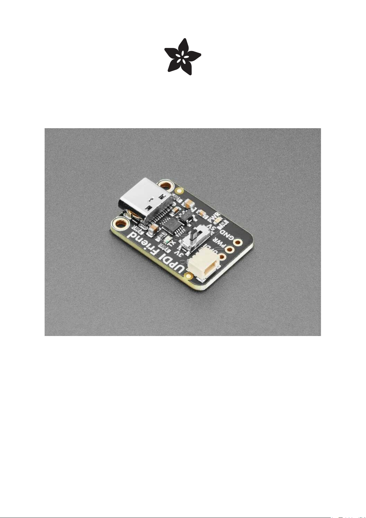
Adafruit UPDI Friend
Created by Liz Clark
https://learn.adafruit.com/adafruit-updi-friend
Last updated on 2024-04-16 01:51:04 PM EDT
©Adafruit Industries Page 1 of 14
Page 2

Table of Contents
Overview
Pinouts
• Power Pins
• UPDI Pin
• JST SH Port
• Voltage Selector Switch
• LEDs
Using the UPDI Friend
• Building a UPDI Programmer
• Wiring with the UPDI Friend
• Install megaTinyCore
• Program the ATtiny
• Blink Test
megaTinyCore Docs
Downloads
• Files
• Schematic and Fab Print
3
5
6
13
13
©Adafruit Industries Page 2 of 14
Page 3

Overview
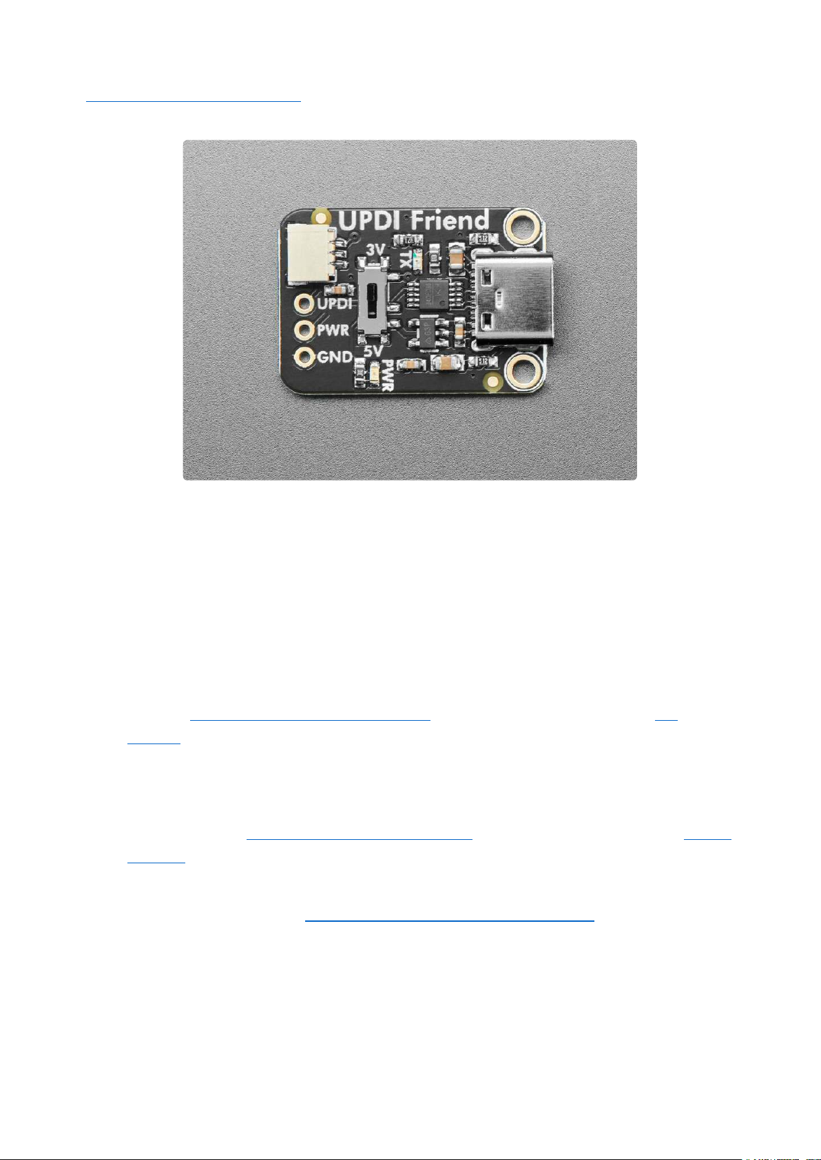
UPDI stands for Unified Program and Debug Interface(https://adafru.it/19eD), but this
board is so smol and cute that we will call it the Unusually Playful Device Interfacer
and pat its head when it does a good job. It's designed to make programming modern
ATtiny chips very easy because it has 3V or 5V power and logic select, power and
transmit indicator LEDs, and a quick cable for poking into a breadboard.
We have been working a lot with ATtiny816, ATtiny817and ATtiny1616 chips(https://
adafru.it/19eE) lately for our seesaw boards. And we're often needing to program
them with a CP2102-based breakout(http://adafru.it/5335) with a 1K resistor soldered
©Adafruit Industries Page 3 of 14
Page 4
between the RX and TX pins(https://adafru.it/18ED). But we were hankering for a nicer
programmer!
This UPDI Friend makes programming such chips very easy:
Select between 3V or 5V power and logic - the 3V regulator can source up to
•
500mA so it can run even big projects.
CH340E USB Serial converter chip with cross-platform drivers.
•
1K Loop-back Resistor between RX and TX.
•
USB Type C for data and power connection to any computer.
•
JST SH cable included for quick plugging into a breadboard - you can get
•
another JST SH 3-pin cable with sockets(http://adafru.it/5765) or with pin
header(http://adafru.it/5755) here.
0.1" spaced breakout holes for custom connections.
•
Green power OK LED
•
Red serial activity LED
•
Inspired by this open-source hardware design(https://adafru.it/19eF) from Stefan
•
Wagner(https://adafru.it/19eG)!
We use Arduino IDE with the megaTinyCore board support package(https://adafru.it/
VdM) installed, simply select "Serial UPDI" as the programmer type. We use 230Kbps
but 56Kbps is also good.
©Adafruit Industries Page 4 of 14
Page 5
Pinouts
Power Pins
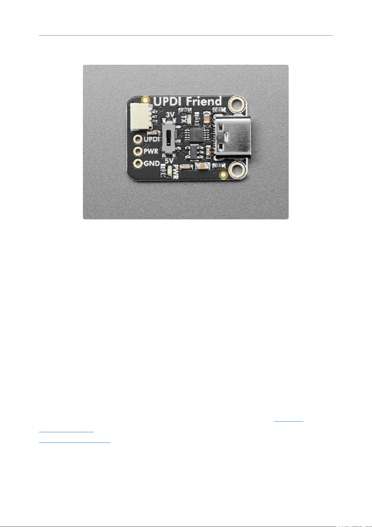
PWR - this is the power output pin from the USB-C port. It can output 3V or 5V
•
depending on the position of the voltage selector switch.
GND - common ground for power and logic.
•
UPDI Pin
UPDI - This is the logic output from the UPDI Friend. Connect it to the UPDI data
•
pin on the board you are programming. Its logic level is determined by the
position of the voltage selector switch (3V or 5V).
JST SH Port
The JST SH port is located above the UPDI, PWR and GND pin. It lets you connect to
those same pins without any soldering using a 3 pin JST SH cable. A male pin
connector cable(http://adafru.it/5755) is included with the UPDI Friend. Optionally, a
socket pin connector(http://adafru.it/5765) version is available.
The red wire is connected to PWR, the black wire is connected to GND and the white
wire is connected to UPDI.
©Adafruit Industries Page 5 of 14
Page 6
Voltage Selector Switch
In the middle of the board is the voltage selector switch. You can use this switch to
change the power and logic level to 3V or 5V. The 3V regulator can source up to
500mA.
LEDs
Power LED - Below the voltage switch is the power LED, labeled PWR. It is the
•
green LED.
Serial activity LED - To the right of the voltage switch is the serial activity LED,
•
labeled TX. It is the red LED. It will light up anytime data is transferred to the
UPDI pin.
Using the UPDI Friend
We don't provide any support for custom builds of seesaw - but we think this
information is cool and useful for the Maker community!
You can reprogram these ATtiny breakouts to run your own firmware. However, the
boards do not come with a bootloader. If you want to do development on seesaw (e.g.
changing the configuration) you need a separate UPDI programming setup! You can
build this setup with a 1K resistor and a USB to Serial cable or with the UPDI Friend
board.
Adafruit UPDI Friend - USB Serial UPDI
Programmer
UPDIstands for
https://www.adafruit.com/product/5879
©Adafruit Industries Page 6 of 14
Page 7
USB to TTL Serial Cable - Debug /
Console Cable for Raspberry Pi
The cable is easiest way ever to connect
to your microcontroller/Raspberry Pi/WiFi
router serial console port. Inside the big
USB plug is a USB<->Serial conversion
chip and at...
https://www.adafruit.com/product/954
Through-Hole Resistors - 1.0K ohm 5%
1/4W - Pack of 25
ΩMG! You're not going to be able to resist
these handy resistor packs!Well, axially,
theydo all of the resisting for you!This is a
25 Pack of...
https://www.adafruit.com/product/4294
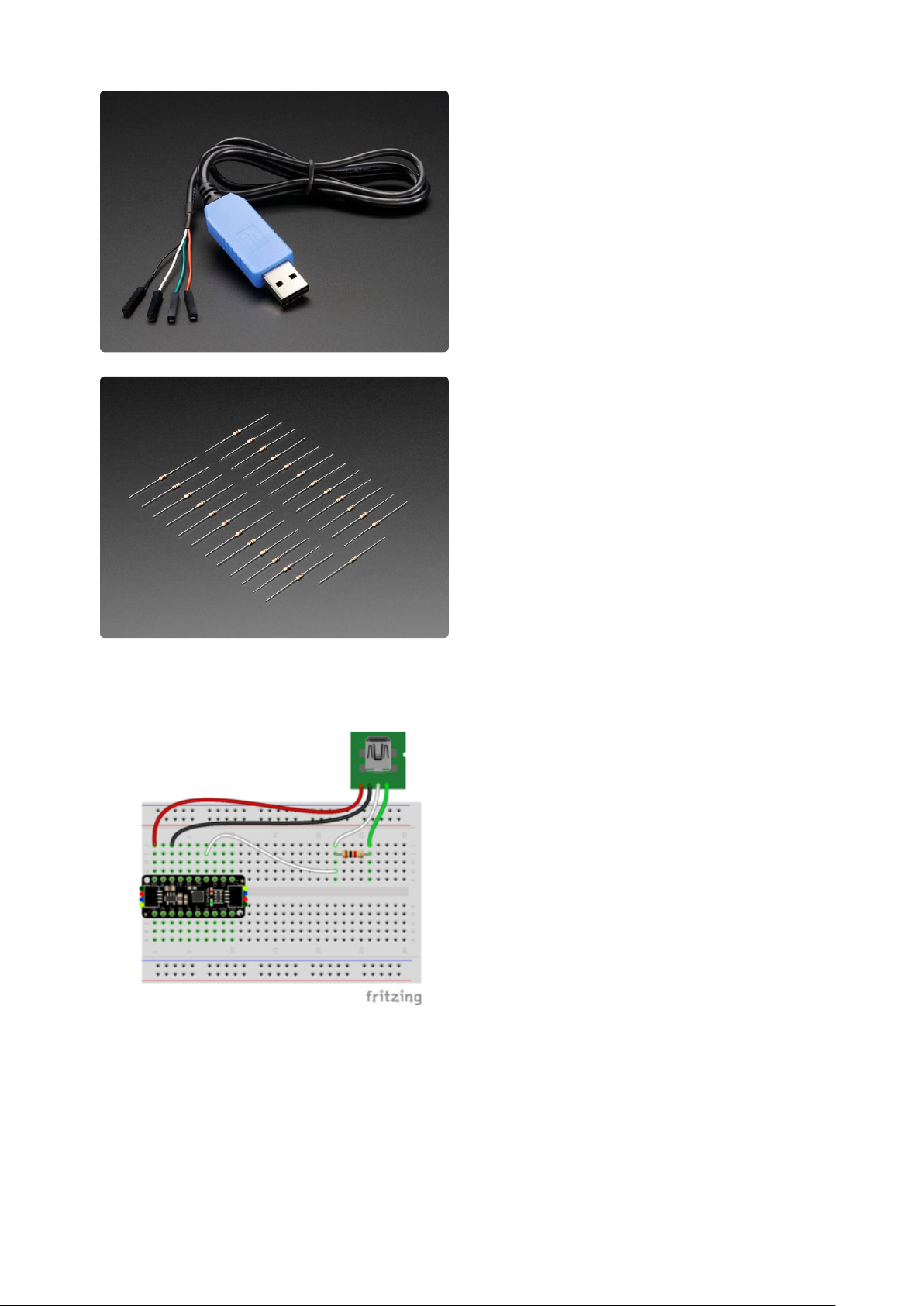
Building a UPDI Programmer
USB to Serial cable power to ATtiny VIN
(red wire)
USB to Serial cable ground to ATtiny G
(black wire)
USB to Serial cable RX to 1K resistor
(white wire)
USB to Serial cable TX to 1K resistor
(green wire)
1K resistor to ATtiny UPDI pin (white wire)
©Adafruit Industries Page 7 of 14
Page 8
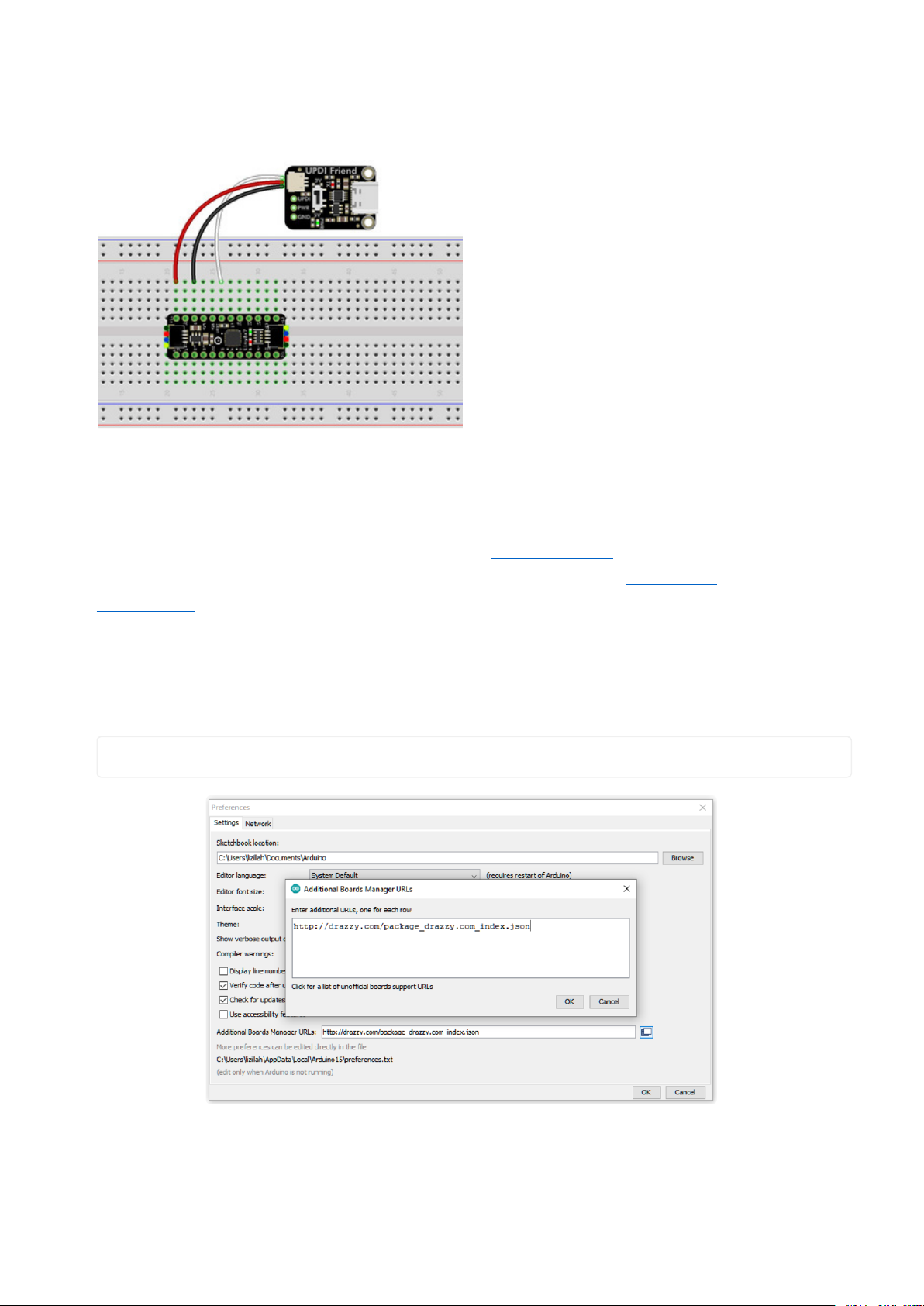
Wiring with the UPDI Friend
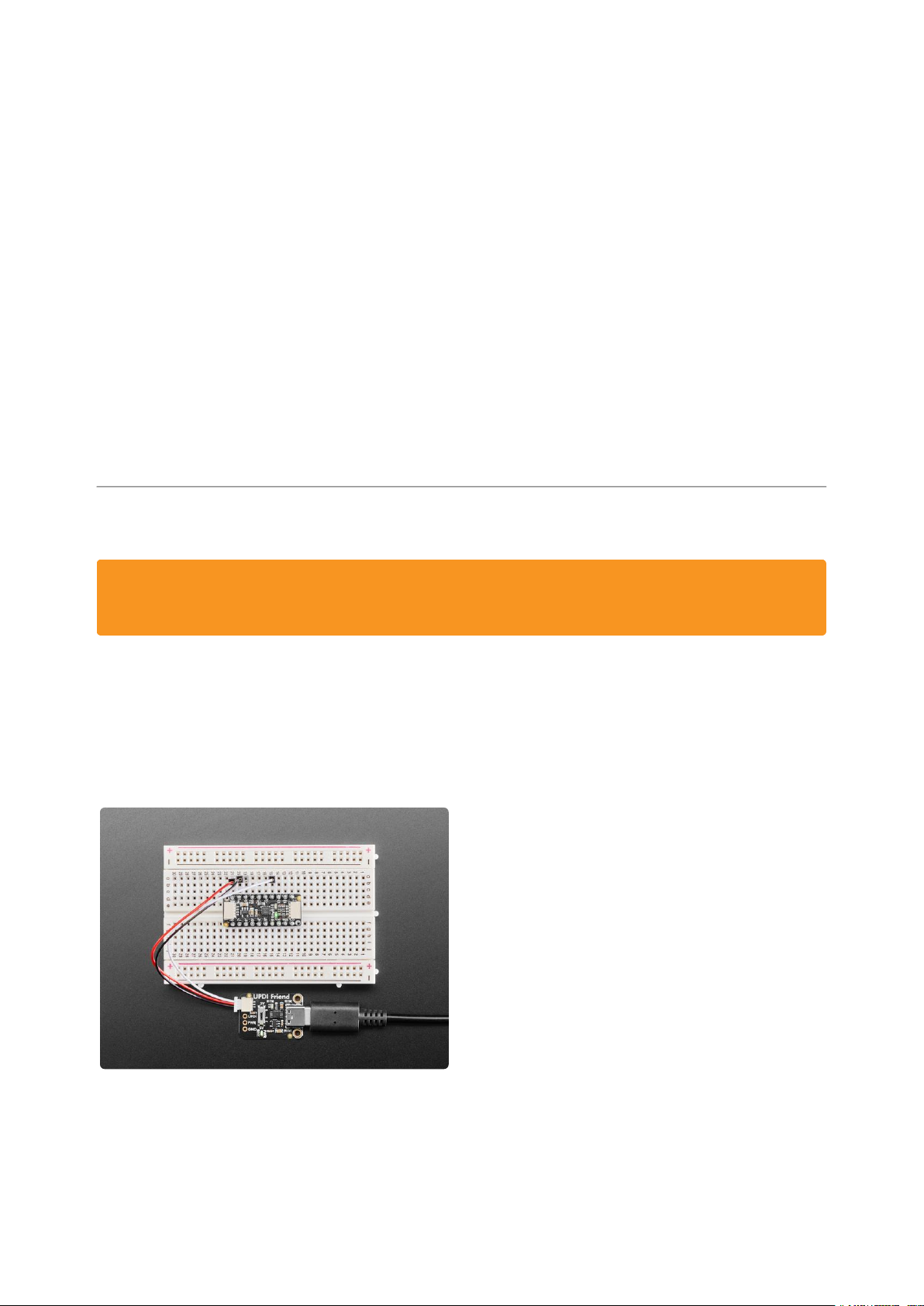
UPDI Friend PWR to ATtiny VIN (red wire)
UPDI Friend GND to ATtiny G (black wire)
UPDI Friend UPDI to ATtiny UPDI pin
(white wire)
Install megaTinyCore
You can compile code for the ATtiny using the megaTinyCore(https://adafru.it/VdM)
board support package in the Arduino IDE. There are detailed installation
instructions(https://adafru.it/19e4) in the megaTinyCore GitHub repository. The
following steps outline how to install it using the Boards Manager.
In the Arduino IDE, go to Preferences and add the megaTinyCore boards manager
URL to the Additional Boards Manager URLs list:
http://drazzy.com/package_drazzy.com_index.json
Go to Tools - Board - Boards Manager...
©Adafruit Industries Page 8 of 14
Page 9
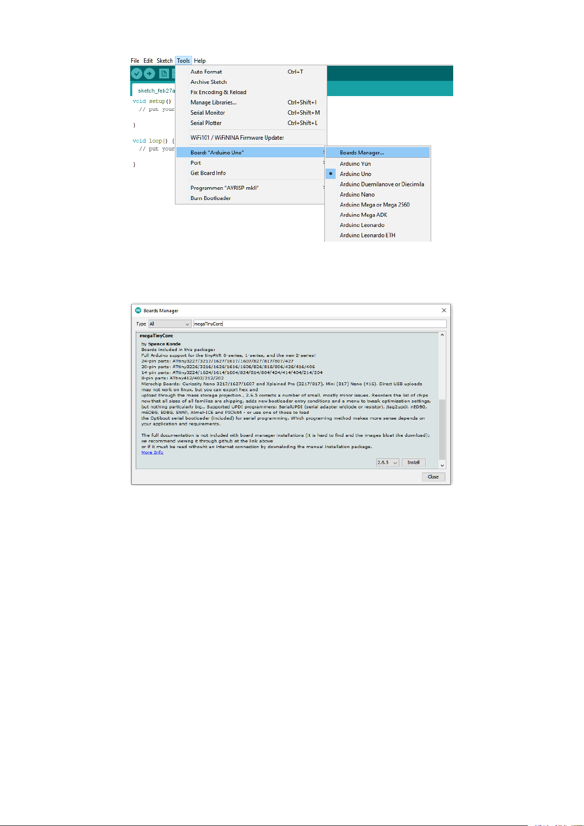
In the Boards Manager, search for megaTinyCore. Click Install to install the board
support package.
Program the ATtiny
After the megaTinyCore finishes installing, go to Tools - Board - megaTinyCore and
select the board list that includes your ATtiny.
©Adafruit Industries Page 9 of 14
Page 10
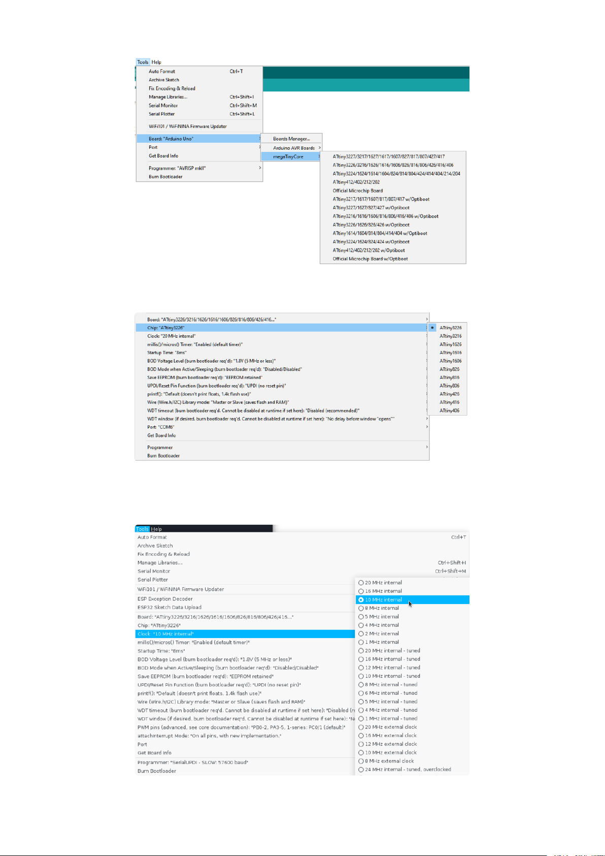
Then, select the chip of your ATtiny.
Next, set clock if needed. The default 20 MHz clock option is only valid if powering
with 5V. If powering with 3.3V, select 10 MHz for the clock.
©Adafruit Industries Page 10 of 14
Page 11
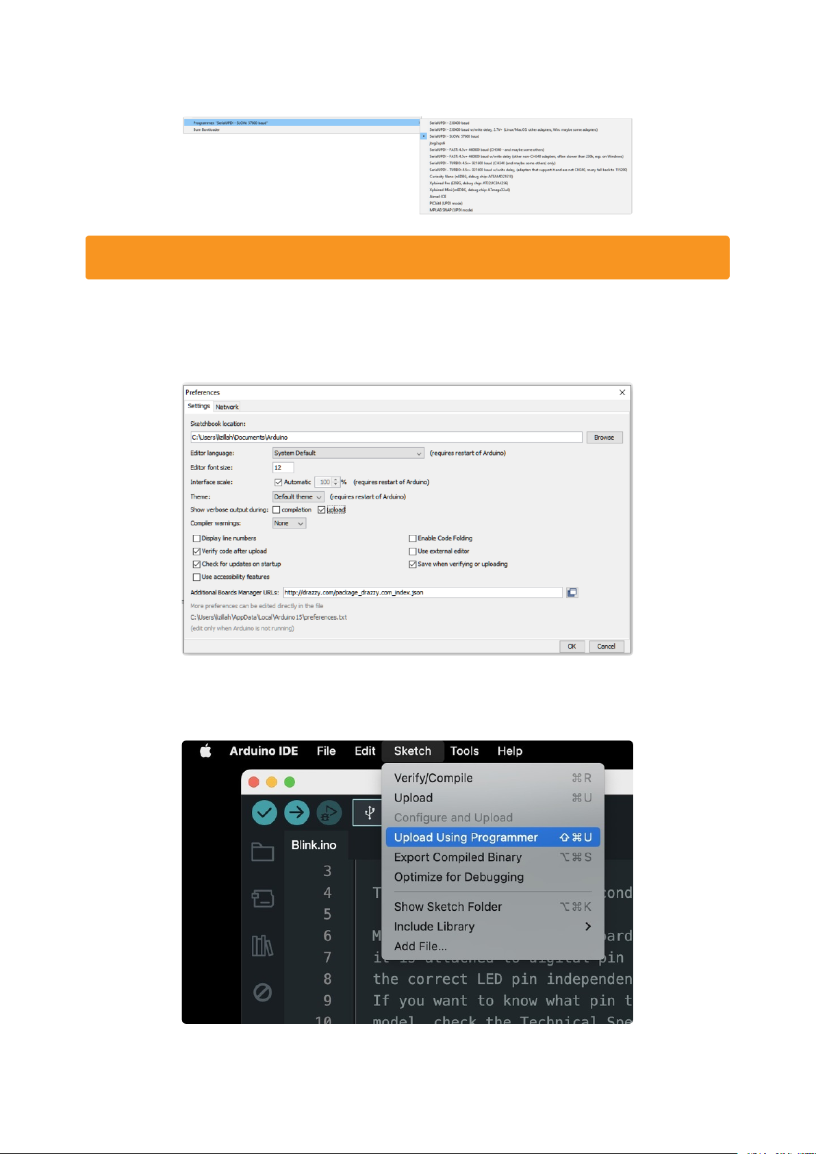
Under Programmer, select SerialUPDI - SLOW: 57600 baud.
Other options can be left at their defaults.
Finally, go to Preferences and check ON Show verbose output during upload. This
will give you the upload details and progress in the monitor at the bottom of the
Arduino IDE, which is very useful for debugging.
Now you can compile code with the megaTinyCore to upload to the ATtiny with the
UPDI programmer by going to Sketch > Upload Using Programmer.
©Adafruit Industries Page 11 of 14
Page 12
Blink Test
This simple example blinks the ATTiny816 onboard red indicator LED on pin 10.
void setup() {
pinMode(10, OUTPUT);
}
void loop() {
digitalWrite(10, HIGH);
delay(1000);
digitalWrite(10, LOW);
delay(1000);
}
If using this with the ATTiny817, you'll want to update the pin to 5, as shown below.
void setup() {
pinMode(5, OUTPUT);
}
void loop() {
digitalWrite(5, HIGH);
delay(1000);
digitalWrite(5, LOW);
delay(1000);
}
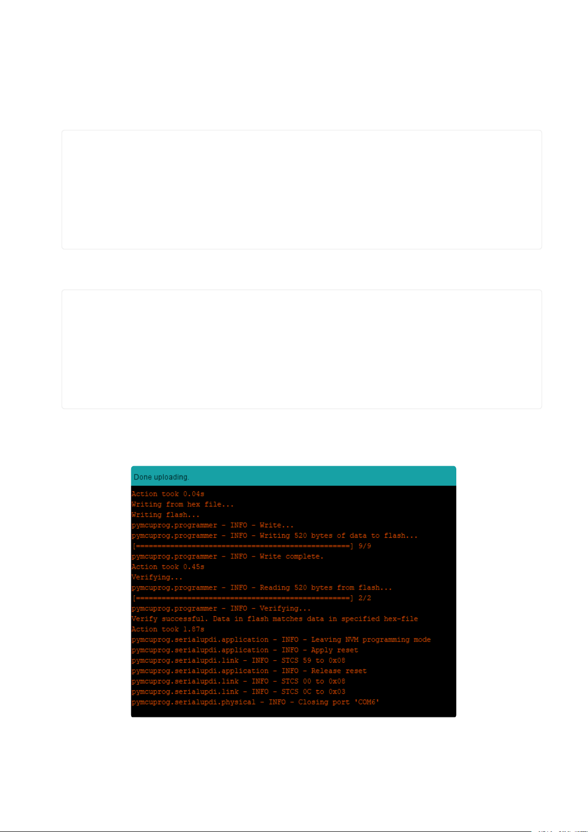
Upload the sketch using the UPDI programmer. You should see this output in the
monitor after the upload has completed successfully:
The red LED on the ATtiny should be blinking!
©Adafruit Industries Page 12 of 14
Page 13
megaTinyCore Docs
megaTinyCore Docs(https://adafru.it/VdM)
Downloads
Files
Window and Mac driver download(https://adafru.it/19eH)
•
CH340E Datasheet(https://adafru.it/19eI)
•
UPDI Interface Docs(https://adafru.it/19eJ)
•
EagleCAD PCB files on GitHub(https://adafru.it/19eK)
•
Fritzing object in the Adafruit Fritzing Library(https://adafru.it/19eL)
•
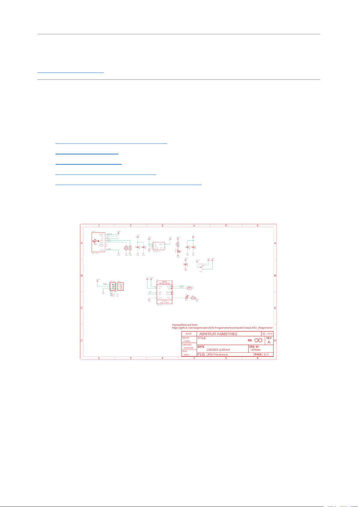
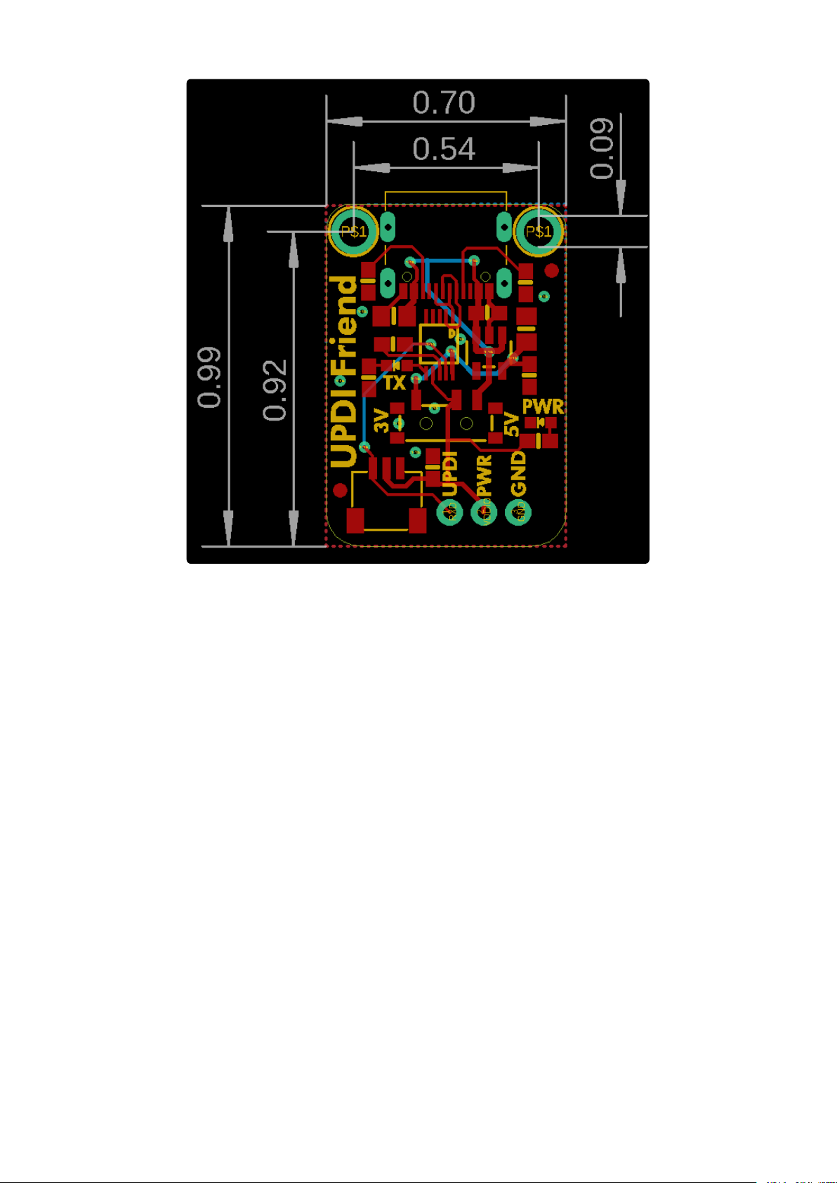
Schematic and Fab Print
©Adafruit Industries Page 13 of 14
Page 14
©Adafruit Industries Page 14 of 14
 Loading...