

Page 1
Adafruit STEMMA Analog SPDT Switch
Created by Liz Clark
https://learn.adafruit.com/adafruit-stemma-analog-spdt-switch
Last updated on 2024-04-05 02:10:38 PM EDT
©Adafruit Industries Page 1 of 12
Page 2

Table of Contents
Overview
Pinouts
• Power Pins
• Selection Signal Input
• STEMMA JST PH
• Analog Switch Inputs and Output
• Signal LED and Jumper
• Power LED and Jumper
CircuitPython
• CircuitPython Microcontroller Wiring
• CircuitPython Usage
• Example Code
Arduino
• Wiring
• Example Code
Downloads
• Files
• Schematic and Fab Print
3
5
7
9
11
©Adafruit Industries Page 2 of 12
Page 3
Overview
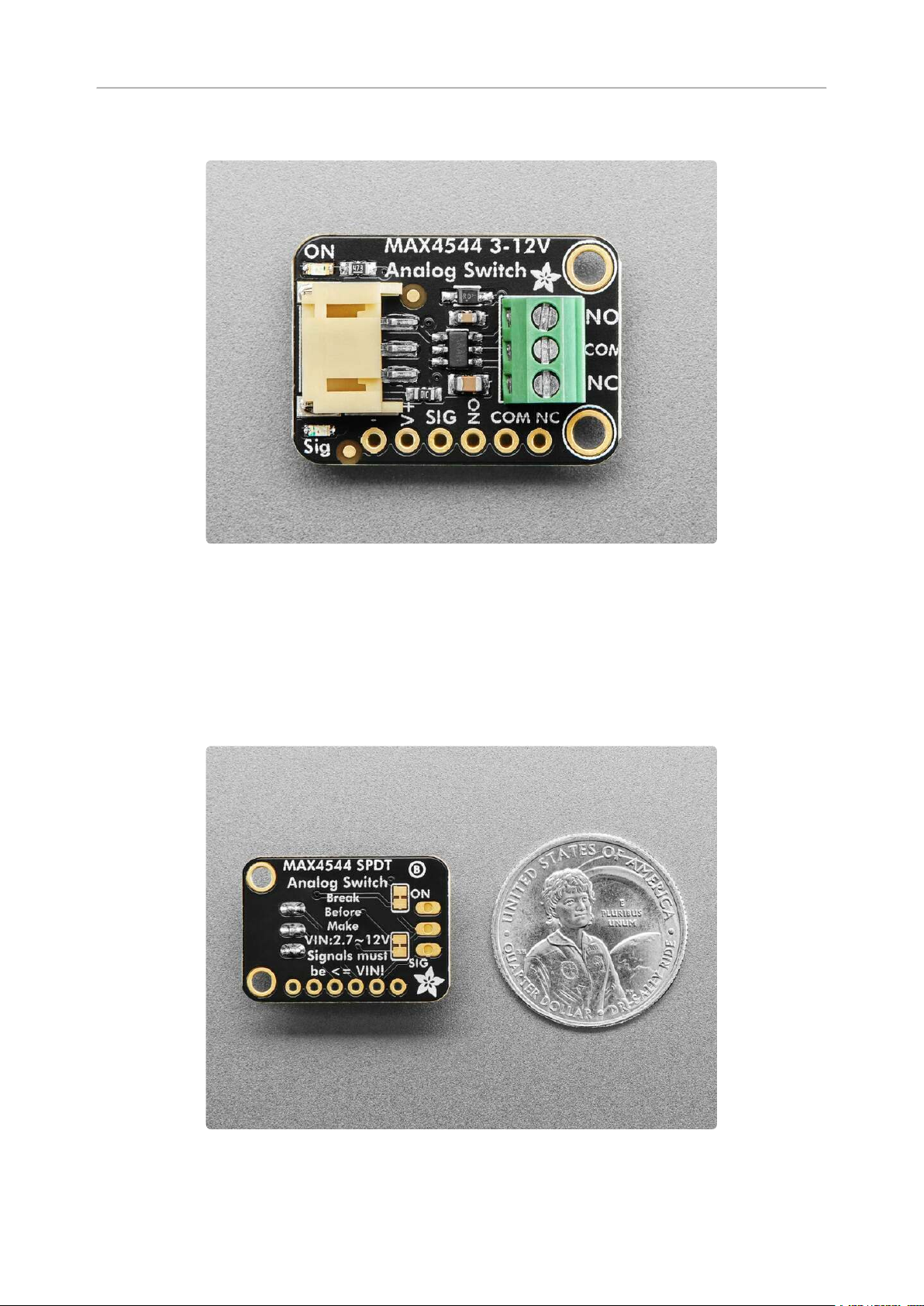
Analog switches are a solid state alternative to relays, when you want a smaller,
lower-power technology that won't wear out mechanically. As the name implies, you
can use an analog switch chip to select between two analog signals, much like a
mechanical switch. These chips tend to be tiny surface mount parts, so the Adafruit
STEMMA Analog SPDT Switch lets anyone use the MAX4544 SPDT analog switch for
signals up to 12V, without fiddly soldering.
When the selection signal is low, the Common pin is connected to the Normally
Closed (NC) pin and disconnected from the Normally Open (NO) pin. When the
©Adafruit Industries Page 3 of 12
Page 4
selection signal is high, the Common pin is connected to NO and disconnected from
NC.
Unlike a relay or mechanical switch, analog switches don't wear out, and the switch
time is near instant, about 30nS. The MAX4544chip also guarantees break-before-
make so the NC and NO pins will never accidentally cross-connect.
However, there's a few things to watch out for:
The V+ power pin (also the red wire if using a STEMMA cable) must be as high
•
as the highest analog voltages you want to switch. That means if the analog
signals are no more than 6VDC, the V+ pin must be higher than 6V. You cannot
power this pin with 3.3V and switch 12V signals.
The MAX4544 cannot switch signals below ground. No negative voltages can
•
be applied to the COM/NO/NC pins!
Analog switches are for signals, not power! Since this is not a mechanical
•
switch, the signals pass through circuitry that is not designed to source or sink
current. This is great for analog signal voltages, and is not good for providing
more than a few mA of current.
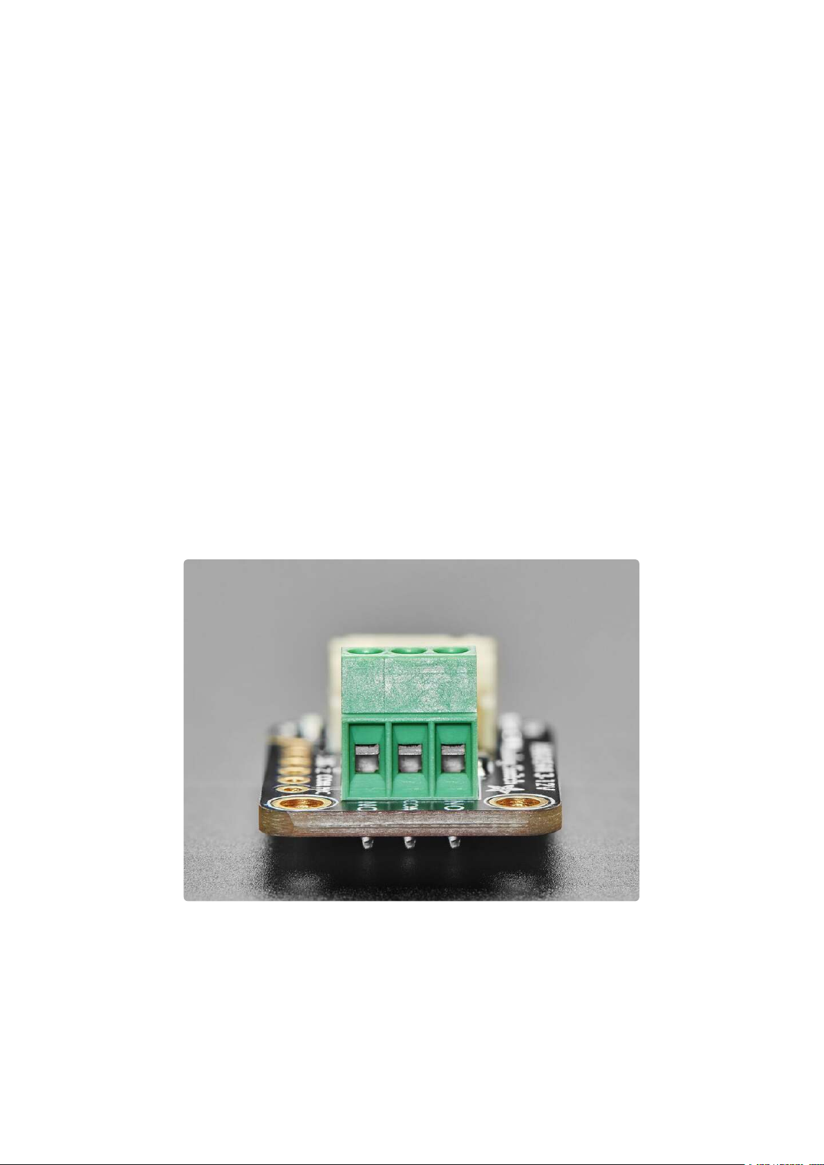
This board has a simple plug-and-play JST PH (2mm pitch) input connector for
solderless use. Provide V+ power (from 3V up to 12V) and signal of at least 2.5VDC
logic level. On the output is a terminal block with the common, Normally Open and
Normally Closed signals. You can also get to all the signal and power pins on a 0.1"
breakout header if desired.
©Adafruit Industries Page 4 of 12
Page 5
Pinouts
Power Pins
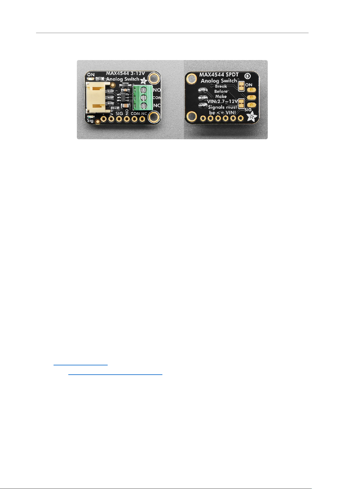
V+ -power input for the MAX4544. It is the red wire on the JST PH cable. You
•
can use 3-12VDC. The voltage must as high as the highest analog voltages you
want to switch. That means if the analog signals are no more than 6VDC, the V+
pin must be higher than 6V. You cannot power this pin with 3.3V and switch 12V
signals.
- - common ground for power and logic.
•
Selection Signal Input
SIG - this is the selection signal input for the MAX4544. It expects a digital (high
•
or low) signal from your microcontroller with a minimum logic level of 2.5VDC.
When it is low, the Common pin is connected to the Normally Closed (NC) pin
and disconnected from the Normally Open (NO) pin. When it is high, the Commo
n pin is connected to NO and disconnected from NC.
STEMMA JST PH
STEMMA JST PH(https://adafru.it/Ft4) - 2mm pitch STEMMA JST port for use
•
with 3-pin STEMMA JST PH cables(https://adafru.it/JRA). It has connections for:
GND/- - common ground for power and data. It is the black wire on the JST
◦
PH cable.
V+ - power input for the MAX4544. It is the red wire on the JST PH cable.
◦
SIG - signal from your microcontroller. It needs to be have a minimum
◦
2.5VDC logic level. It is the white wire on the JST PH cable.
©Adafruit Industries Page 5 of 12
Page 6

Analog Switch Inputs and Output
You'll connect your analog signals to NO and NC. The state of the SIG pin will
determine which analog signal is output to common.
These pins expect an analog signal voltage, not a power voltage. Since this is not a
mechanical switch, the signals pass through circuitry that is not designed to source or
sink current. Additionally, the MAX4544 cannot switch signals below ground. No
negative voltages can be applied to these pins.
NO - this is the Normally Open pin. It is connected to the common pin when the
•
SIG pin is high.
NC - this is the Normally Closed pin. It is connected to the common pin when
•
the SIG pin is low.
COM - this is the common output from the MAX4544 switch. The selected
•
analog signal from NO or NC will be output to this pin.
These pins are available along the side edge of the board or via the 3-pin terminal
block.
Signal LED and Jumper
Signal LED - to the left of the JST PH connector is the signal LED, labeled Sig. It
•
is the red LED. It will light up when SIG is high and turn off when SIG is low.
LED jumper - in the upper right corner on the back of the board is a jumper for
•
the signal LED. It is labeled SIG on the board silk. If you want to disable the
signal LED, cut the trace on this jumper.
Power LED and Jumper
Power LED - to the right of the JST PH connector is the power LED, labeled ON.
•
It is the green LED.
LED jumper - in the upper left corner on the back of the board is a jumper for
•
the power LED. It is labeled ON on the board silk. If you want to disable the
power LED, cut the trace on this jumper.
©Adafruit Industries Page 6 of 12
Page 7
CircuitPython
It's easy to use the STEMMA Analog SPDT Switch with CircuitPython and the
digitalio(https://adafru.it/19lD) and analogio(https://adafru.it/19lE) core modules.
These modules allow you to easily write Python code for accessing basic digital or
analog inputs and outputs.
CircuitPython Microcontroller Wiring
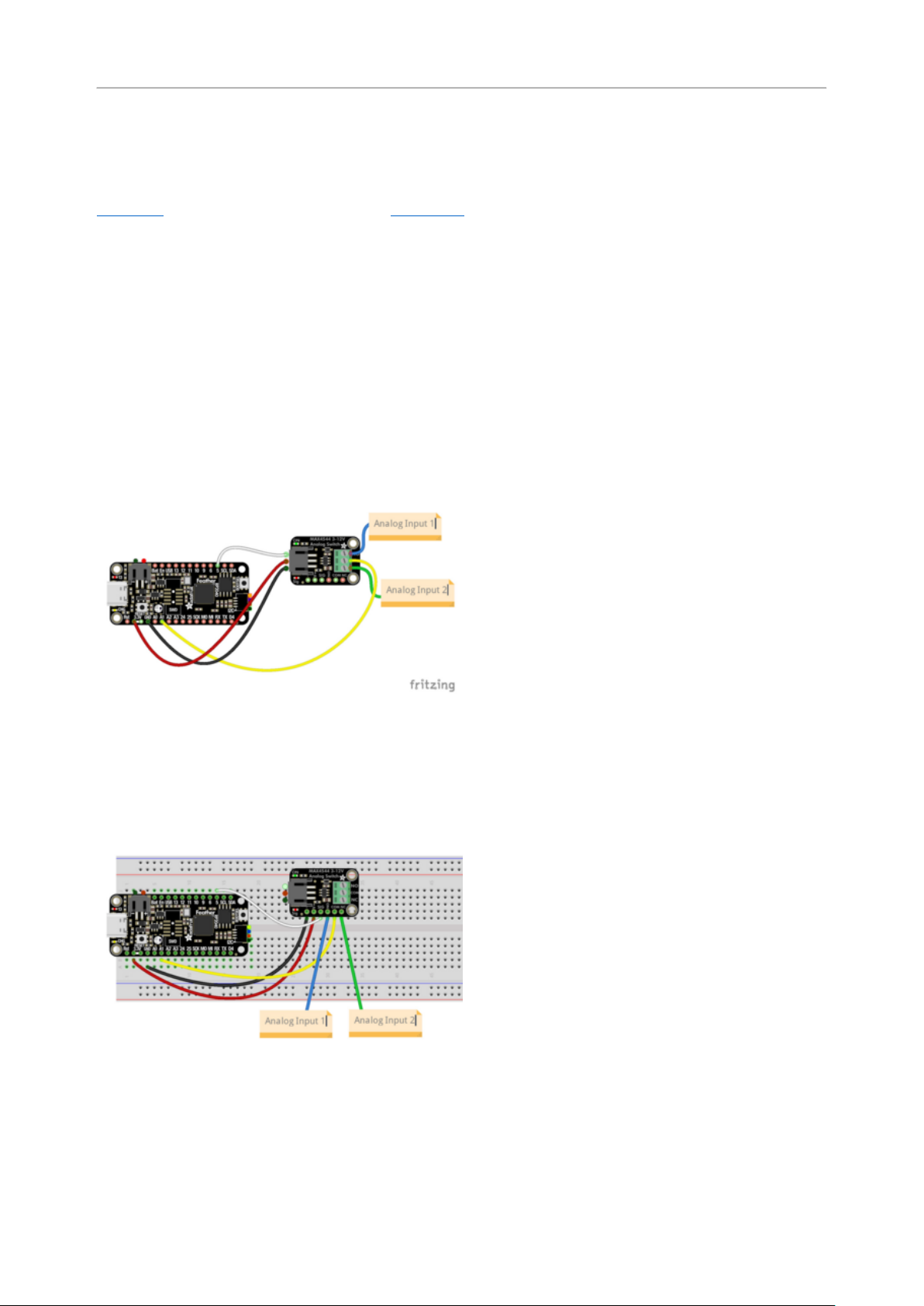
First wire up the switch to your board exactly as follows. The following is the switch
wired to a Feather RP2040 (shown using a JST PH cable). You'll connect your two
external analog inputs to NO and NC.
Board 3V to switch JST PH VIN (red wire)
Board GND to switch JST PH GND (black
wire)
Board pin 5to switch JST PH SIG (white
wire)
Board pin A1 to switch terminal block
common (yellow wire)
Analog input 1 to switch terminal block
NO (blue wire)
Analog input 2 to switch terminal block
NC (green wire)
The following is the switch wired to a Feather RP2040 using a solderless breadboard:
Board 3V to switch VIN (red wire)
Board GND to switch GND (black wire)
Board pin 5to switch SIG (white wire)
Board pin A1 to switch common (yellow
wire)
Analog input 1 to switch NO (blue wire)
Analog input 2 to switch NC (green wire)
CircuitPython Usage
To use with CircuitPython, you need to update code.py with the example script.
©Adafruit Industries Page 7 of 12
Page 8
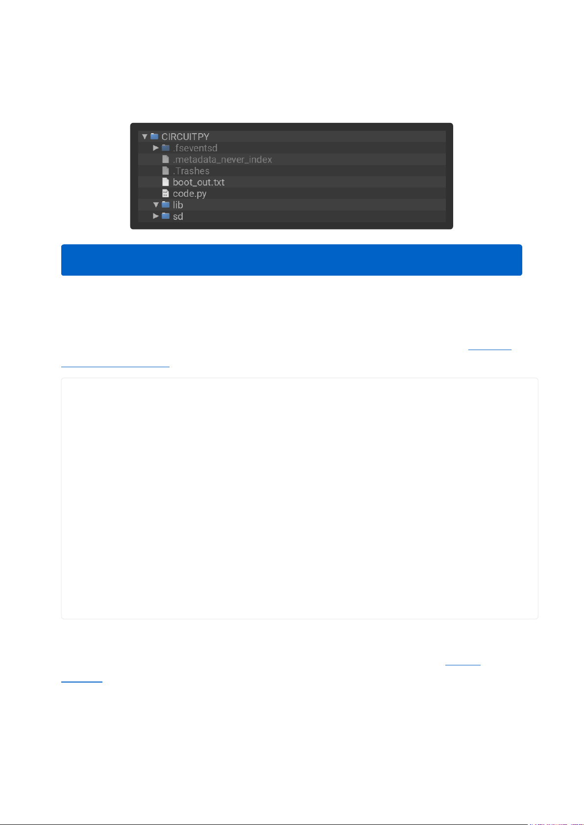
In the example below, click the Download Project Bundle button below to download
the code.py file in a zip file. Extract the contents of the zip file, and copythe code.py
file to your CIRCUITPY drive.
No additional libraries are needed in the /lib folder for this example.
Example Code
If running CircuitPython: Once everything is saved to the CIRCUITPY drive, connect
to the serial console(https://adafru.it/Bec) to see the data printed out!
# SPDX-FileCopyrightText: 2024 Liz Clark for Adafruit Industries
# SPDX-License-Identifier: MIT
import time
import board
from digitalio import DigitalInOut, Direction
from analogio import AnalogIn
analog_in = AnalogIn(board.A1)
switch = DigitalInOut(board.D5)
switch.direction = Direction.OUTPUT
switch_time = 2
clock = time.monotonic()
while True:
if (time.monotonic() - clock) > switch_time:
switch.value = not switch.value
print(switch.value)
clock = time.monotonic()
print((analog_in.value,))
time.sleep(0.1)
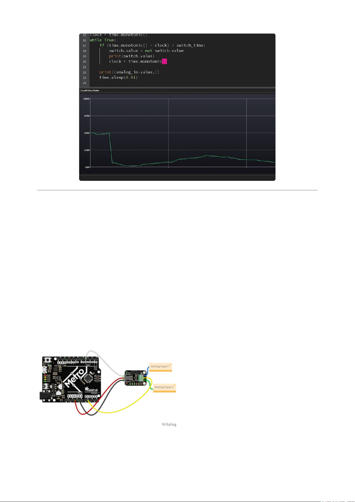
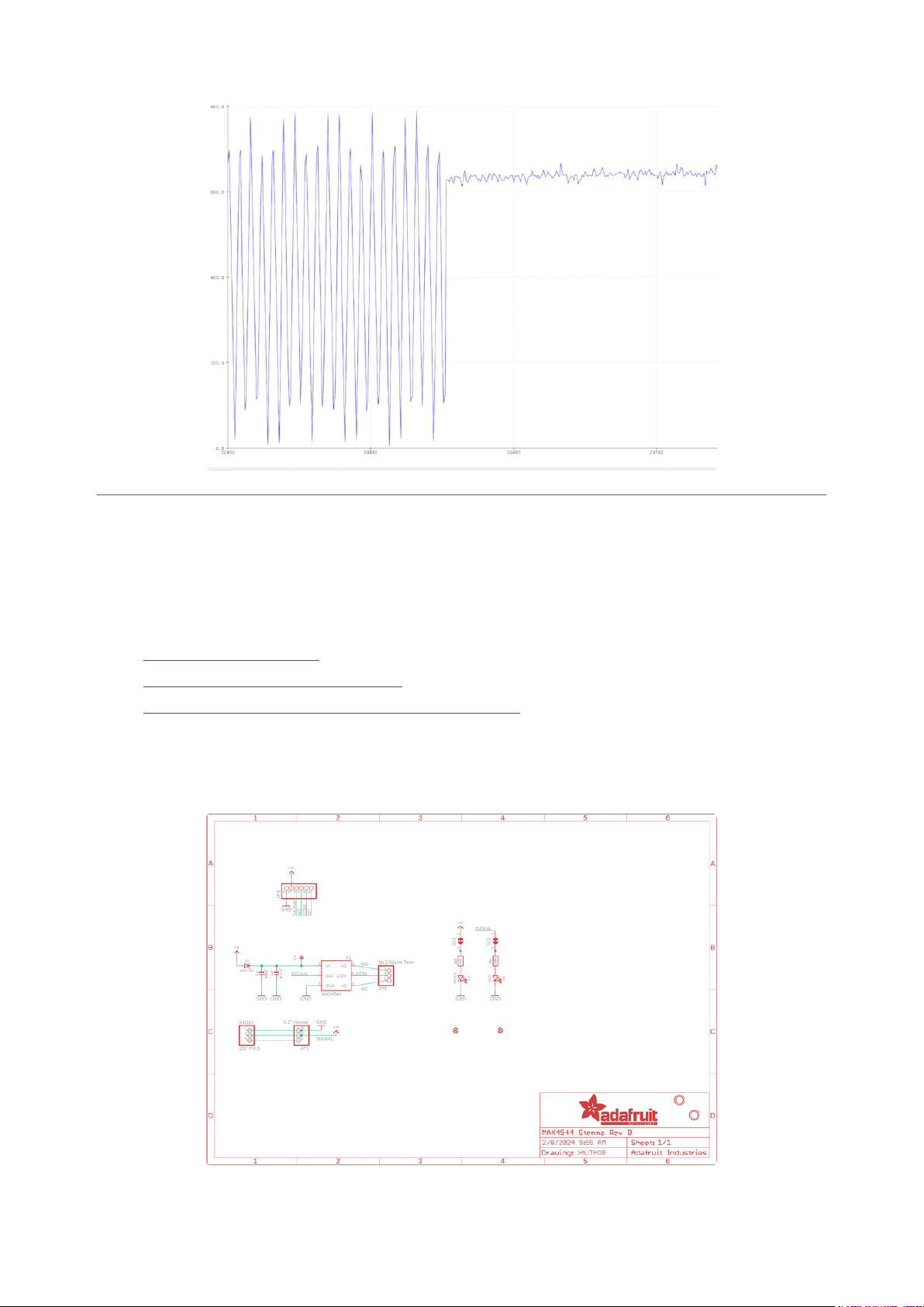
Every 2 seconds, the analog output from the common pin will be switched by pin 5
toggling high or low. You can see this in action with Mu, by opening the Plotter
window(https://adafru.it/CTM) in the REPL.
©Adafruit Industries Page 8 of 12
Page 9
Arduino
Using the STEMMA Analog SPDT Switch with Arduino involves wiring up the breakout
to your Arduino-compatible microcontroller and running the provided example code.
Wiring
Wire as shown for a 5V board like an Uno. If you are using a 3V board, like an Adafruit
Feather, wire the board's 3V pin to the breakout VIN.
Here is an Adafruit Metro wired up to the breakout using the JST PH connector. You'll
connect your two external analog inputs to NO and NC.
Board 5V to switch JST PH VIN (red wire)
Board GND to switch JST PH GND (black
wire)
Board pin 5to switch JST PH SCL (white
wire)
Board pin A1 to switch terminal block
common (yellow wire)
Analog input 1 to switch terminal block
NO (blue wire)
Analog input 2 to switch terminal block
NC (green wire)
Here is an Adafruit Metro wired up using a solderless breadboard:
©Adafruit Industries Page 9 of 12
Page 10
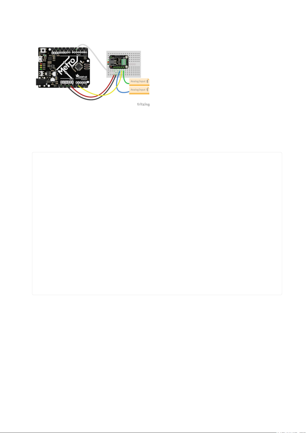
Board 5V to switch VIN (red wire)
Board GND to switch GND (black wire)
Board pin 5to switch SIG (white wire)
Board pin A1 to switch common (yellow
wire)
Analog input 1 to switch NO (blue wire)
Analog input 2 to switch NC (green wire)
Example Code
// SPDX-FileCopyrightText: 2024 Liz Clark for Adafruit Industries
//
// SPDX-License-Identifier: MIT
int analogIn = A1;
int digitalOut = 5;
int analogValue = 0;
unsigned long timer = 2000;
unsigned long startTime = millis();
void setup() {
Serial.begin(115200);
pinMode(digitalOut, OUTPUT);
}
// the loop function runs over and over again forever
void loop() {
analogValue = analogRead(analogIn);
Serial.println(analogValue);
if ((millis() - startTime) >= timer) {
digitalWrite(digitalOut, !digitalRead(digitalOut));
startTime = millis();
}
delay(10);
}
Upload the sketch to your board and open up the Serial Plotter (Tools -> Serial
Plotter) at 115200 baud. You'll see the analog data printed to the plotter. Every 2
seconds, the analog output from the common pin will be switched by toggling pin 5
high or low.
©Adafruit Industries Page 10 of 12
Page 11
Downloads
Files
MAX4544 Datasheet(https://adafru.it/19lF)
•
EagleCAD PCB files on GitHub(https://adafru.it/19ma)
•
Fritzing object in the Adafruit Fritzing Library(https://adafru.it/19mb)
•
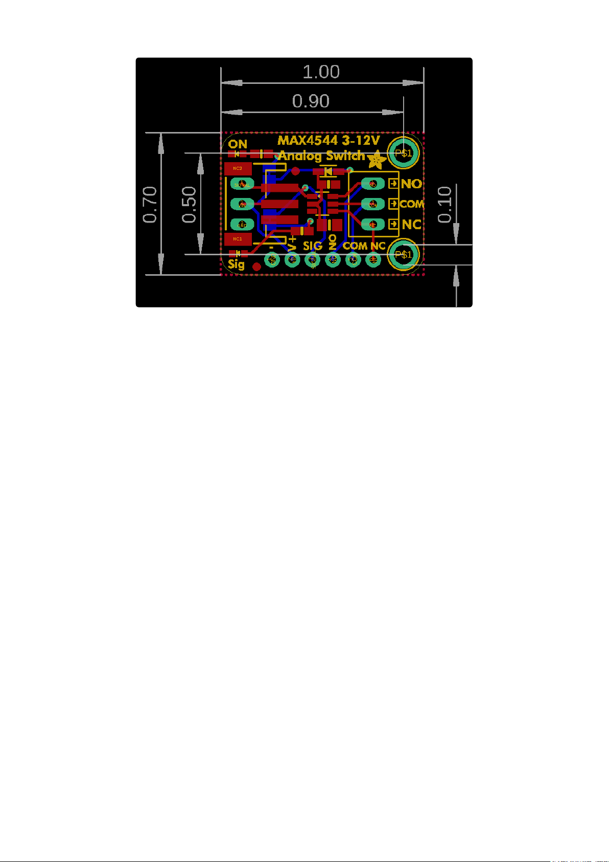
Schematic and Fab Print
©Adafruit Industries Page 11 of 12
Page 12
©Adafruit Industries Page 12 of 12
 Loading...