

Page 1
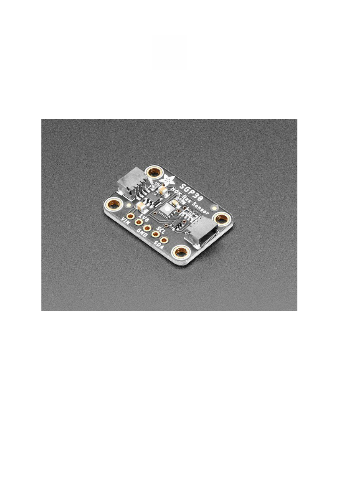
Adafruit SGP30 TVOC/eCO2 Gas Sensor
Created by lady ada
https://learn.adafruit.com/adafruit-sgp30-gas-tvoc-eco2-mox-sensor
Last updated on 2021-11-15 07:06:28 PM EST
©Adafruit Industries Page 1 of 22
Page 2

Table of Contents
Overview
Pinouts
• Data Pins
• Power Pins:
Arduino Test
• Wiring
• Install Adafruit_SGP30 library
• Load Demo
• Baseline Set & Get
Arduino Library Docs
Python & CircuitPython Test
• CircuitPython MicroController Wiring
• Python Computer Wiring
• CircuitPython Installation of SGP30 Library
• Python Installation of SGP30 Library
• CircuitPython & Python Usage
• Baseline Set & Get
3
6
7
7
7
8
9
10
12
13
13
13
14
15
16
17
18
Python Library Docs
Download
• Files:
• Schematic STEMMA QT Version
• Fabrication Print STEMMA QT Version
• Schematic & Fabrication Print Original Version
20
20
20
20
21
21
©Adafruit Industries Page 2 of 22
Page 3
Overview
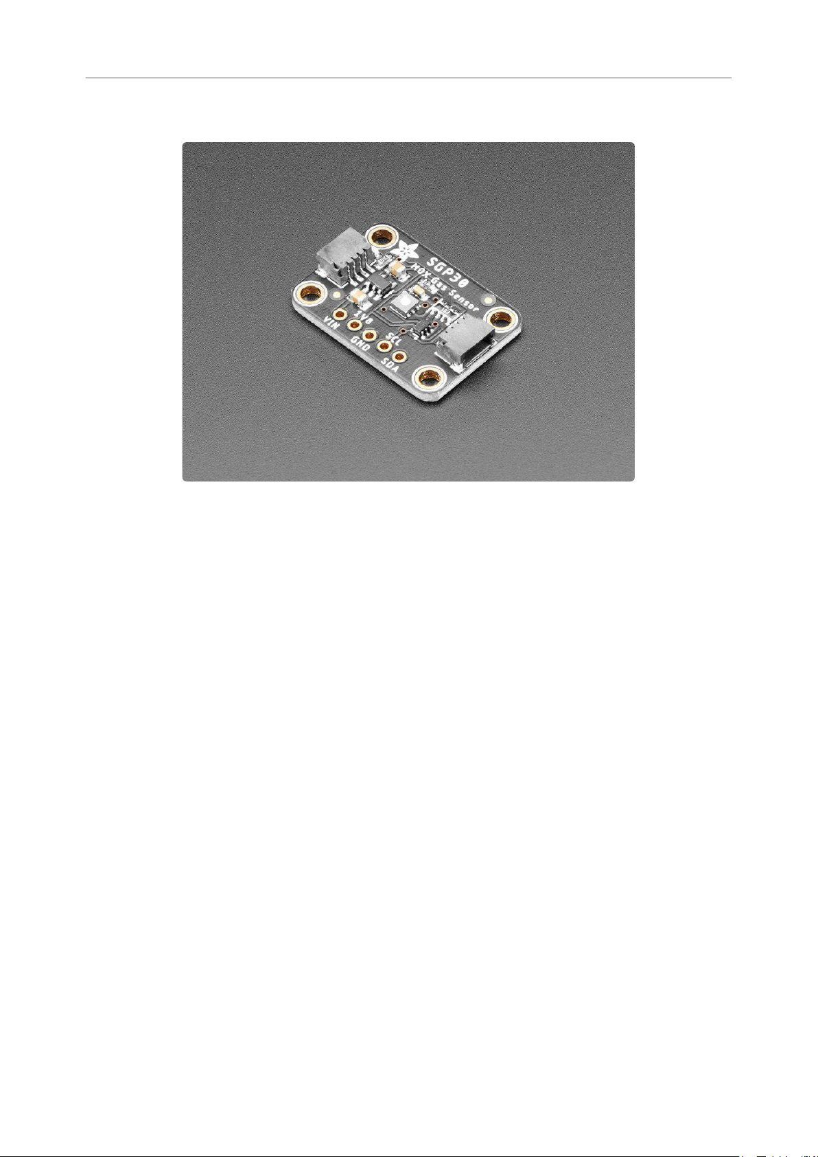
Breathe easy with the SGP30 Multi-Pixel Gas Sensor, a fully integrated MOX gas
sensor. This is a very fine air quality sensor from the sensor experts at Sensirion, with
I2C interfacing and fully calibrated output signals with a typical accuracy of 15% within
measured values. The SGP combines multiple metal-oxide sensing elements on one
chip to provide more detailed air quality signals.
This is a gas sensor that can detect a wide range of Volatile Organic Compounds
(VOCs) and H2 and is intended for indoor air quality monitoring. When connected to
your microcontroller (running our library code) it will return a Total Volatile Organic
Compound (TVOC) reading and an equivalent carbon dioxide reading (eCO2) over
I2C.
©Adafruit Industries Page 3 of 22
Page 4
The SGP30 has a 'standard' hot-plate MOX sensor, as well as a small microcontroller
that controls power to the plate, reads the analog voltage, tracks the baseline
calibration, calcluates TVOC and eCO2 values, and provides an I2C interface to read
from. Unlike the CCS811, this sensor does not require I2C clock stretching.
This part will measureeCO2(equivalent calculated carbon-dioxide) concentration
within a range of 400 to 60,000 parts per million (ppm), andTVOC(Total Volatile
Organic Compound) concentration withina range of0 to 60,000 parts per
billion(ppb).
©Adafruit Industries Page 4 of 22
Page 5
Please note, this sensor, like all VOC/gas sensors, has variability and to get precise
measurements you will want to calibrate it against known sources! That said, for
general environmental sensors, it will give you a good idea of trends and comparison.
The SGP30 does have built in calibration capabilities, note that eCO2 is calculated
based on H2 concentration, it is not a 'true' CO2 sensor for laboratory use.
Another nice element to this sensor is the ability to set humidity compensation for
better accuracy. An external humidity sensor is required and then the RH% is written
over I2C to the sensor, so it can better calculate the TVOC/eCO2 values.
Nice sensor right? So we made it easy for you to get right into your next project. The
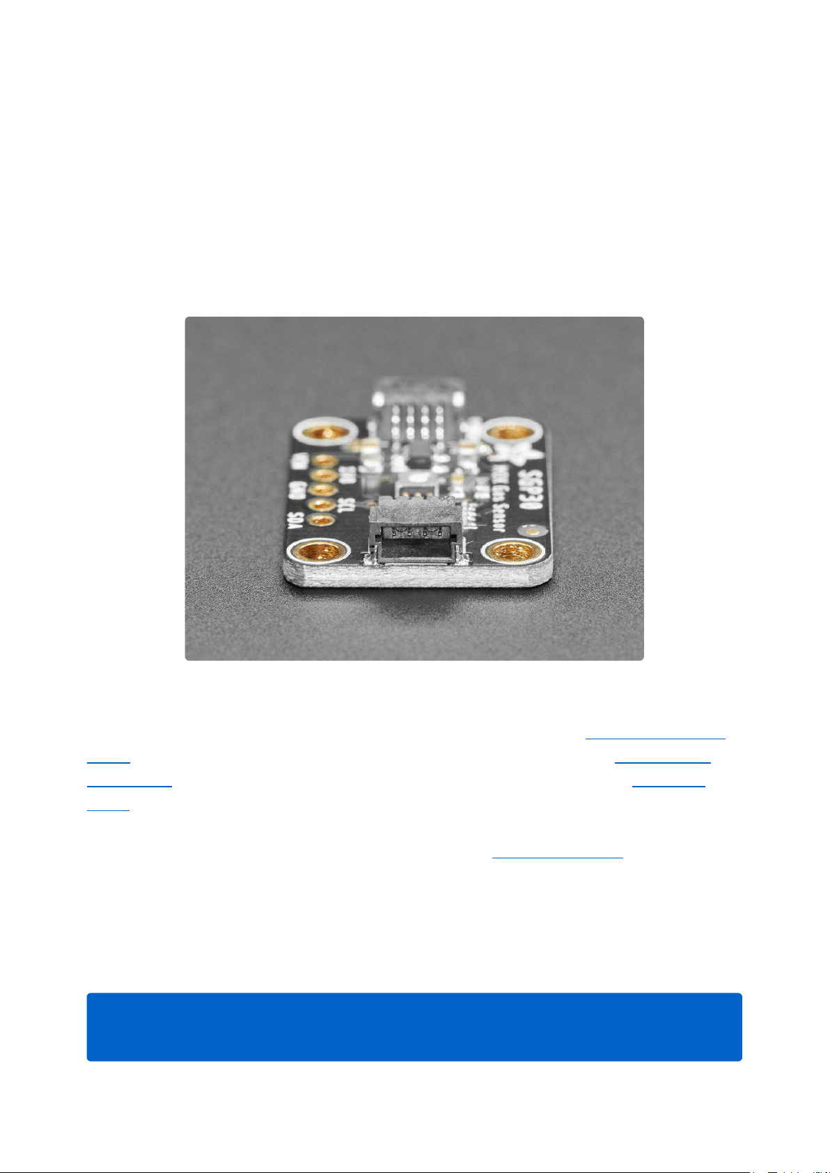
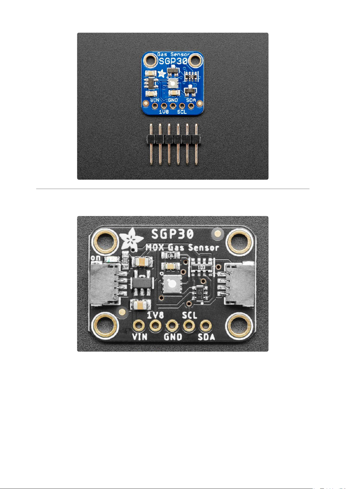
surface-mount sensor is soldered onto a custom made PCB in theSTEMMA QTform
factor(https://adafru.it/LBQ), making them easy to interface with. TheSTEMMA QT
connectors(https://adafru.it/JqB)on either side are compatible with theSparkFun
Qwiic(https://adafru.it/Fpw)I2C connectors. This allows you to make solderless
connections between your development board and the SGP30 or to chain it with a
wide range of other sensors and accessories using acompatible cable(https://
adafru.it/JnB).
We’ve of course broken out all the pins to standard headers and added a 1.8V voltage
regulator and level shifting so allow you to use it with either 3.3V or 5V systems such
as the Raspberry Pi, or Metro M4 or Arduino Uno.
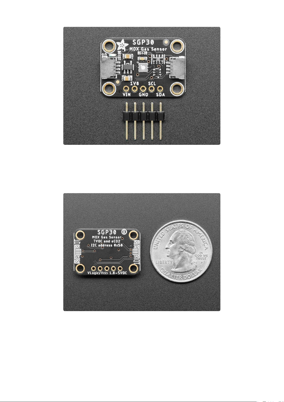
There are two versions of this board - the STEMMA QT version shown above, and
the original header-only version shown below. Code works the same on both!
©Adafruit Industries Page 5 of 22
Page 6
Pinouts
©Adafruit Industries Page 6 of 22
Page 7
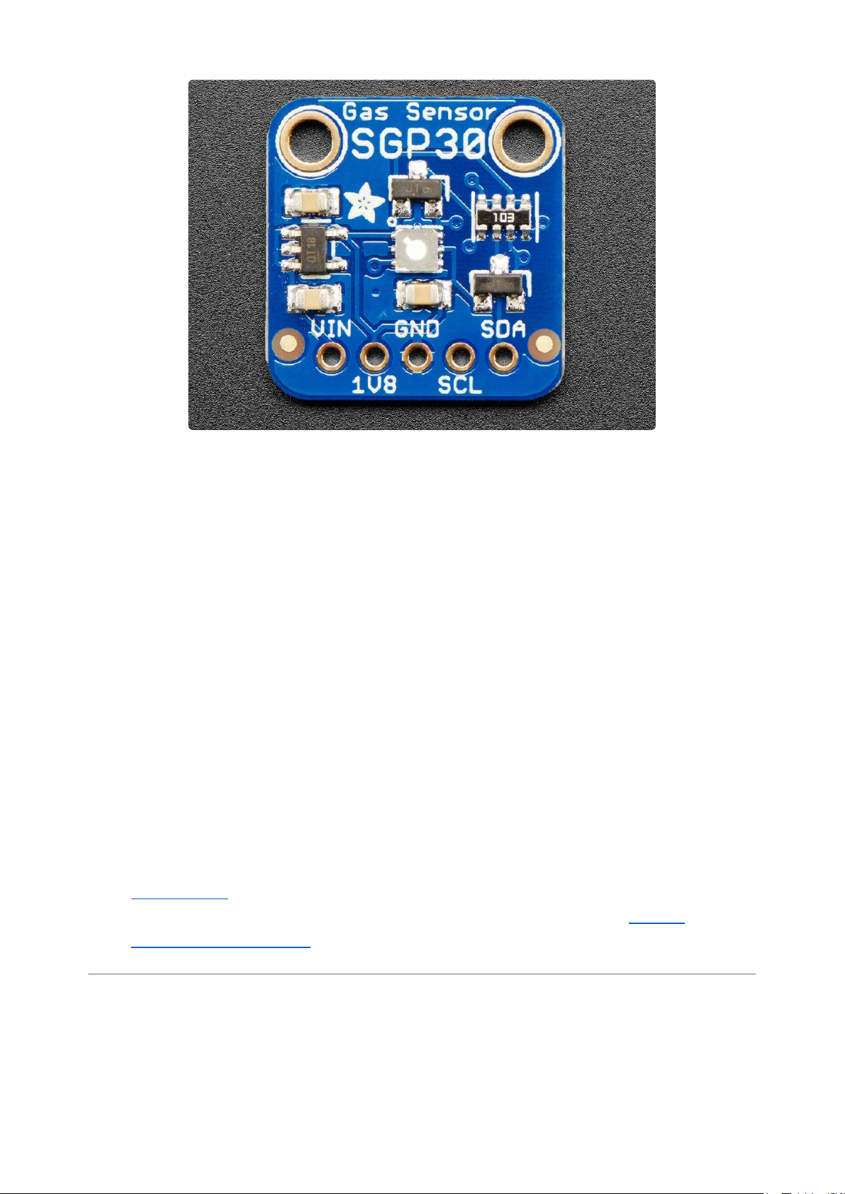
Power Pins:
Vin - this is the power pin. Since the sensor chip uses 3 VDC for logic, we have
•
included a voltage regulator on board that will take 3-5VDC and safely convert it
down. To power the board, give it the same power as the logic level of your
microcontroller - e.g. for a 5V micro like Arduino, use 5V
1V8 - this is the 1.8V output from the voltage regulator, you can grab up to 50mA
•
from this if you like
GND - common ground for power and logic
•
Data Pins
SCL - I2C clock pin, connect to your microcontrollers I2C clock line. Can use 3V
•
or 5V logic, and has a 10K pullup to Vin
SDA - I2C data pin, connect to your microcontrollers I2C data line. Can use 3V or
•
5V logic, and has a 10K pullup to Vin
STEMMA QT(https://adafru.it/Ft4)- These connectors allow you to connectors to
•
dev boards withSTEMMA QT connectors or to other things withvarious
associated accessories(https://adafru.it/Ft6)
Arduino Test
You can easily wire this breakout to any microcontroller; we'll be using an Arduino.
©Adafruit Industries Page 7 of 22
Page 8

Start by soldering the headers to the SGP30 breakout board. Check out the Adafruit
guide to excellent soldering(https://adafru.it/dxy) if you're new to soldering. Then
continue on below to learn how to wire it to a Metro.
The sensor uses I2C address 0x58 and cannot be changed.
Wiring
Connect the SGP30 breakout to your board using an I2C connection. Here's an
example with an Arduino-compatible Metro:
©Adafruit Industries Page 8 of 22
Page 9

Board 5V to Sensor Vin (red wire on
•
STEMMA QT version). (Metro is a 5V
logic chip)
Board ground / GND to sensor
•
ground / GND (black wire on
STEMMA QT version).
Board SCL to sensor SCL (yellow
•
wire on STEMMA QT version).
Board SDA to sensor SDA (blue
•
wire on STEMMA QT version).
Metro Original Fritzing File
https://adafru.it/At6
Install Adafruit_SGP30 library
To begin reading sensor data, you will need to install the Adafruit_SGP30 library
(code on our github repository)(https://adafru.it/BnZ). It is available from the Arduino
library manager so we recommend using that.
©Adafruit Industries Page 9 of 22
Page 10

From the IDE open up the library manager...
And type in adafruit sgp30 to locate the library. Click Install
Load Demo
Open up File->Examples->Adafruit_SGP30->sgp30test and upload to your
microcontroller wired up to the sensor
Then open up the serial console at 115200 baud, you'll see the serial number printed
out - this is a unique 48-bit number burned into each chip. Since you may want to do
per-chip calibration, this can help keep your calibration detail separate
©Adafruit Industries Page 10 of 22
Page 11

The first 10-20 readings will always be TVOC 0 ppb eCO2 400 ppm . That's because
the sensor is warming up, so it will have 'null' readings.
After a few seconds, you will see the TVOC and eCO2 readings fluctuate:
Every minute or so you'll also get a Baseline value printed out. More about that later!
You can take a bit of alcohol on a swap and swipe it nearby to get the readings to
spike
©Adafruit Industries Page 11 of 22
Page 12

That's it! The sensor pretty much only does that - all the calculations for the TVOC and
eCO2 are done within the sensor itself, no other data is exposed beyond the
'baseline' values
Baseline Set & Get
All VOC/gas sensors use the same underlying technology: a tin oxide element that,
when exposed to organic compounds, changes resistance. The 'problem' with these
sensors is that the baseline changes, often with humidity, temperature, and other non-
gas-related-events. To keep the values coming out reasonable, you'll need to
calibrate the sensor.
If no stored baseline is available after initializing the baseline algorithm,
the sensor has to run for 12 hours until the baseline can be stored. This will
ensure an optimal behavior for the next time it starts up. Reading out the
baseline prior should be avoided unless a valid baseline is restored first.
Once the baseline is properly initialized or restored, the current baseline
value should be stored approximately once per hour. While the sensor is
off, baseline values are valid for a maximum of seven days.
Restarting the sensor without reading back a previously stored baseline
will result in the sensor trying to determine a new baseline. The
adjustement algorithm will be accelerated for 12hrs which is the Maximum
time required to find a new baseline.
The sensor adjusts to the best value it has been exposed to. So keeping it
indoors the sensor thinks this is the best value and sets it to ~0ppb tVOC
and 400ppm CO2eq. As soon as you expose the sensor to outside air it
can adjust to the global H2 Background Signal. For normal Operation
exposing the sensor to outside air for 10min cumulative time should be
sufficient.
©Adafruit Industries Page 12 of 22
Page 13

If you're experienced with sensors that don't have a baseline, you either
won't be able to measure absolute values or you'll have to implement your
own baseline algorithm.
The sensor to sensor variation of SGP30 in terms of sensitivity is very good
as each of them is calibrated. But the baseline has to be determined for
each sensor individually during the first Operation.
To make that easy, SGP lets you query the 'baseline calibration readings' from the
sensor with code like this:
uint16_t TVOC_base, eCO2_base;
sgp.getIAQBaseline(&eCO2_base, &TVOC_base);
This will grab the two 16-bit sensor calibration words and place them in the variables
so-named.
You should store these in EEPROM, FLASH or hard-coded. Then, next time you start
up the sensor, you can pre-fill the calibration words with sgp.setIAQBaseline(eCO2
_baseline, TVOC_baseline);
Arduino Library Docs
Arduino Library Docs(https://adafru.it/AuL)
Python & CircuitPython Test
It's easy to use the SGP30 sensor with Python or CircuitPython and the Adafruit
CircuitPython SGP30(https://adafru.it/Bn-) module. This module allows you to easily
write Python code that reads the TVOC, eCO2, and more from the sensor.
You can use this sensor with any CircuitPython microcontroller board or with a
computer that has GPIO and Python thanks to Adafruit_Blinka, our CircuitPython-for-
Python compatibility library(https://adafru.it/BSN).
CircuitPython MicroController Wiring
Connect the SGP30 breakout to your board using an I2C connection, exactly as
shown on the previous page for Arduino. Here's an example with a Feather M0:
©Adafruit Industries Page 13 of 22
Page 14

Board 3.3V to sensor Vin (red wire
•
on STEMMA QT version) (Feather is
3.3V logic)
Board ground / GND to sensor
•
ground / GND (black wire on
STEMMA QT version).
Board SCL to sensor SCL (yellow
•
wire on STEMMA QT version).
Board SDA to sensor SDA (blue
•
wire on STEMMA QT version).
Feather Original Fritzing file
https://adafru.it/At8
Python Computer Wiring
Since there's dozens of Linux computers/boards you can use we will show wiring for
Raspberry Pi. For other platforms, please visit the guide for CircuitPython on Linux to
see whether your platform is supported(https://adafru.it/BSN).
©Adafruit Industries Page 14 of 22
Page 15

Here's the Raspberry Pi wired with I2C:
Pi 3V3 tosensor VIN (red wire on
•
STEMMA QT version)
Pi GND tosensor GND (black wire
•
on STEMMA QT version)
Pi SCL tosensor SCL (yellow wire
•
on STEMMA QT version)
Pi SDA tosensor SDA (blue wire on
•
STEMMA QT version)
CircuitPython Installation of SGP30 Library
To use the SGP30 you'll need to install theAdafruit CircuitPython SGP30(https://
adafru.it/Bn-) library on your CircuitPython board.
First make sure you are running thelatest version of Adafruit CircuitPython(https://
adafru.it/Amd)for your board.
©Adafruit Industries Page 15 of 22
Page 16

Next you'll need to install the necessary librariesto use the hardware--carefully follow
the steps to find and install these libraries fromAdafruit's CircuitPython library bundle
(https://adafru.it/zdx). Our introduction guide hasa great page on how to install the
library bundle(https://adafru.it/ABU)for both express and non-express boards.
Remember for non-express boards like the, you'll need to manually install the
necessary libraries from the bundle:
adafruit_sgp30.mpy
•
adafruit_bus_device
•
You can also download theadafruit_sgp.mpyfromits releases page on Github(https:
//adafru.it/Bo0).
Before continuing make sure your board's lib folder or root filesystem has theadafrui
t_sgp30.mpy,andadafruit_bus_devicefiles and folderscopied over.
Nextconnect to the board's serial REPL(https://adafru.it/Awz)so you are at the
CircuitPython>>>prompt.
Python Installation of SGP30 Library
You'll need to install the Adafruit_Blinka library that provides the CircuitPython
support in Python. This may also require enabling I2C on your platform and verifying
you are running Python 3. Since each platform is a little different, and Linux changes
often, please visit the CircuitPython on Linux guide to get your computer ready(https
://adafru.it/BSN)!
Once that's done, from your command line run the following command:
sudo pip3 install adafruit-circuitpython-sgp30
•
If your default Python is version 3 you may need to run 'pip' instead. Just make sure
you aren't trying to use CircuitPython on Python 2.x, it isn't supported!
©Adafruit Industries Page 16 of 22
Page 17

CircuitPython & Python Usage
To demonstrate the usage of the sensor we'll initialize it and read the eCO2 and
TVOC data and print it to the REPL
Save this example sketch as main.py on your CircuitPython board:
# SPDX-FileCopyrightText: 2021 ladyada for Adafruit Industries
# SPDX-License-Identifier: MIT
""" Example for using the SGP30 with CircuitPython and the Adafruit library"""
import time
import board
import busio
import adafruit_sgp30
i2c = busio.I2C(board.SCL, board.SDA, frequency=100000)
# Create library object on our I2C port
sgp30 = adafruit_sgp30.Adafruit_SGP30(i2c)
print("SGP30 serial #", [hex(i) for i in sgp30.serial])
sgp30.iaq_init()
sgp30.set_iaq_baseline(0x8973, 0x8AAE)
elapsed_sec = 0
while True:
print("eCO2 = %d ppm \t TVOC = %d ppb" % (sgp30.eCO2, sgp30.TVOC))
time.sleep(1)
elapsed_sec += 1
if elapsed_sec > 10:
elapsed_sec = 0
print(
"**** Baseline values: eCO2 = 0x%x, TVOC = 0x%x"
% (sgp30.baseline_eCO2, sgp30.baseline_TVOC)
)
In the REPL you'll see the serial number printed out: [0x0, 0x64, 0xb878] in this
case. This is a unique 48-bit number burned into each chip. Since you may want to do
per-chip calibration, this can help keep your calibration detail separate
©Adafruit Industries Page 17 of 22
Page 18

The first 10-20 readings will always be eCO2 400 ppm TVOC 0 ppb . That's
because the sensor is warming up, so it will have 'null' readings.
After a few seconds, you will see the TVOC and eCO2 readings fluctuate
Every minute or so you'll also get a Baseline value printed out. More about that later!
You can take a bit of alcohol on a swap and swipe it nearby to get the readings to
spike
That's it! The sensor pretty much only does that - all the calculations for the TVOC and
eCO2 are done within the sensor itself, no other data is exposed beyond the
'baseline' values
Baseline Set & Get
All VOC/gas sensors use the same underlying technology: a tin oxide element that,
when exposed to organic compounds, changes resistance. The 'problem' with these
sensors is that the baseline changes, often with humidity, temperature, and other non-
©Adafruit Industries Page 18 of 22
Page 19

gas-related-events. To keep the values coming out reasonable, you'll need to
calibrate the sensor.
If no stored baseline is available after initializing the baseline algorithm,
the sensor has to run for 12 hours until the baseline can be stored. This will
ensure an optimal behavior for preceding startups. Reading out the
baseline prior should be avoided unless a valid baseline is restored first.
Once the baseline is properly initialized or restored, the current baseline
value should be stored approximately once per hour. While the sensor is
off, baseline values are valid for a maximum of seven days.
Restarting the sensor without reading back a previously stored baseline
will result in the sensor trying to determine a new baseline. The
adjustement algorithm will be accelerated for 12hrs which is the Maximum
time required to find a new baseline.
The sensor adjusts to the best value it has been exposed to. So keeping it
indoors the sensor thinks this is the best value and sets it to ~0ppb tVOC
and 400ppm CO2eq. As soon as you expose the sensor to outside air it
can adjust to the global H2 Background Signal. For normal Operation
exposing the sensor to outside air for 10min cumulative time should be
sufficient.
If you're experienced with sensors that don't have a baseline, you either
won't be able to measure absolute values or you'll have to implement your
own baseline algorithm.
The sensor to sensor variation of SGP30 in terms of sensitivity is very good
as each of them is calibrated. But the baseline has to be determined for
each sensor individually during the first Operation.
To make that easy, SGP lets you query the 'baseline calibration readings' from the
sensor with code like this:
co2eq_base, tvoc_base = sgp30.baseline_co2eq, sgp30.baseline_tvoc
This will grab the two 16-bit sensor calibration words and place them in the variables
so-named.
You should store these in EEPROM, FLASH or hard-coded. Then, next time you start
up the sensor, you can pre-fill the calibration words
with sgp30.set_iaq_baseline(co2eq_base, tvoc_base)
©Adafruit Industries Page 19 of 22
Page 20

Python Library Docs
Python Library Docs(https://adafru.it/C3c)
Download
Files:
SGP30 Datasheet(https://adafru.it/Bo1)
•
Fritzing object in Adafruit Fritzing library(https://adafru.it/aP3)
•
EagleCAD files on GitHub(https://adafru.it/LIe)
•
Schematic STEMMA QT Version
©Adafruit Industries Page 20 of 22
Page 21

Fabrication Print STEMMA QT Version
Schematic & Fabrication Print Original Version
©Adafruit Industries Page 21 of 22
Page 22

©Adafruit Industries Page 22 of 22
 Loading...