

Page 1

Adafruit NeoRGB Stemma
Created by Liz Clark
https://learn.adafruit.com/adafruit-neorgb-stemma
Last updated on 2024-04-04 03:45:30 PM EDT
©Adafruit Industries Page 1 of 25
Page 2

Table of Contents
Overview
Pinouts
• STEMMA JST PH
• Terminal Block
• NeoPixel Signal Input and Output Pins
• Signal LED and Jumper
• Power LED and Jumper
CircuitPython and Python
• CircuitPython Microcontroller Wiring
• Python Computer Wiring
• Python Installation of NeoPixel Library
• CircuitPython Usage
• Python Usage
• Example Code
Python Docs
Arduino
• Wiring
• Library Installation
• Example Code
3
6
8
13
14
Arduino Docs
WipperSnapper
• What is WipperSnapper
• Wiring
• Usage
Downloads
• Files
• Schematic and Fab Print
17
17
24
©Adafruit Industries Page 2 of 25
Page 3

Overview
Whenever we're working with 'true analog' LED strips(https://adafru.it/19fX), that have
1-3 channels of RGB or White LEDs, we wish we had already invented something to
make wiring them easier: controlling these strips takes a bit of wiring since they
almost always need 12VDC and driver FETs.
Now, we've finally created the Adafruit NeoRGB Stemma board - which will make our
lives easier, and maybe even some customer's too!
©Adafruit Industries Page 3 of 25
Page 4

The NeoRGB is a no-soldering, plug-and-play STEMMA board with a 2mm JST PH
connector(http://adafru.it/3893) on one end, and a 5-pin 0.1" screw terminal block on
the other. It can convert standard 800KHzNeoPixelsignal using a WS2811F chip to
AO3406 N-channel FETs(https://adafru.it/19fY) that are high efficiency and can sink a
chunk of current - 3 Amps a piece with 50milliOhm Ron!
Basically, this means that you can treat any PWM-able common-anode RGB LED strip
or LED as a single NeoPixel, at up to 16V and 3 Amps per channel. Perfect for large
analog LEDs or arrays, LED strips, even ones that are not RGB, such as controlling 3
independent single-channel LEDs or strips. Note that the WS2811 bare chips don't
support 4 channels, so this won't work on RGBW strips.
©Adafruit Industries Page 4 of 25
Page 5

Usage is easy. First you'll need a 2mm JST PH cable, such as this one with pins(http://
adafru.it/3893). Then pick one of two powering options
If you are using less than 2A of current total across all 3 channels:
Connect the white wire to your NeoPixel-compatible signal, 3 or 5V logic.
1.
Connect the red wire to 3-16VDC, this will power the LED strip
2.
Connect the black ground wire to your microcontroller and power supply shared
3.
ground
If you are using more than 2A of current total across all 3 channels, you'll need to
wire the power supply to the terminal block since JST PH connectors are only rated
for 2A.
Connect the white wire to your NeoPixel-compatible signal, 3 or 5V logic.
1.
Connect your 3-16V power supply positive pin to the V+ to the terminal block,
2.
keep the red wire from being used by taping it or cutting it off.
Connect the 3-16V power supply ground pin to the GND on the terminal block
3.
Connect the black wire as a 'reference' ground to your microcontroller that is
4.
providing the NeoPixel signal
©Adafruit Industries Page 5 of 25
Page 6

An onboard green ON LED will let you know that it is powered correctly, and a red
Signal LED will lightly blink when data is sent on the Signal line. If you need to chain
more than one, or want to connect some other NeoPixels to the output, there's a pin
for the Output signal on the board.
Pinouts
©Adafruit Industries Page 6 of 25
Page 7

STEMMA JST PH
STEMMA JST PH(https://adafru.it/Ft4) - 2mm pitch STEMMA JST port for use
•
with 3-pin STEMMA JST PH cables(https://adafru.it/JRA). It has connections for:
GND - common ground for power and data. It is the black wire on the JST
◦
PH cable.
VIN - power input for the RGB LED(s). It is the red wire on the JST PH
◦
cable. You can use 3-16VDC. Use the voltage that matches the
requirements for your RGB LEDs (ex: 12V for a 12V strip). The JST PH
connector is rated for 2A input. If you are using more than 2A of current
total across all 3 RGB channels then you need to use the VIN input on
terminal block.
SIG/Neo In - NeoPixel-compatible signal from your microcontroller, 3 or 5V
◦
logic. It is the white wire on the JST PH cable.
If you are using more than 2A of current total across all 3 channels, you'll need to
wire the power supply to the terminal block since JST PH connectors are only
rated for 2A.
Terminal Block
GND - common ground for power and data.
•
VIN - power input for the RGB LED(s). You can use 3-16VDC. Use the voltage
•
that matches the requirements for your RGB LEDs (ex: 12V for a 12V strip). If you
are using more than 2A of current total across all 3 RGB channels, you'll need
to wire the power supply to this input.
RED - red channel output from the WS2811. Connect to the red channel input on
•
your RGB LED strip.
GRN - green channel output from the WS2811. Connect to the green channel
•
input on your RGB LED strip.
BLU - blue channel output from the WS2811. Connect to the blue channel input
•
on your RGB LED strip.
©Adafruit Industries Page 7 of 25
Page 8

NeoPixel Signal Input and Output Pins
On the edges of the board are pins for Neo In and Neo Out. These pins allow you to
connect multiple NeoRGB Stemma boards together.
Neo In - NeoPixel-compatible signal from your microcontroller, 3 or 5V logic.
•
Neo Out - output of the NeoPixel-compatible signal from your microcontroller
•
Signal LED and Jumper
Signal LED - to the left of the JST PH connector is the signal LED, labeled SIG. It
•
is the red LED. It will lightly blink when data is sent on the Neo In/Signal line.
LED jumper - in the upper left corner on the back of the board is a jumper for
•
the signal LED. If you want to disable the signal LED, cut the trace on this
jumper.
Power LED and Jumper
Power LED - to the right of the JST PH connector is the power LED, labeled ON.
•
It is the green LED.
LED jumper - in the upper right corner on the back of the board is a jumper for
•
the power LED. It is labeled LED on the board silk. If you want to disable the
power LED, cut the trace on this jumper.
CircuitPython and Python
It's easy to use the NeoRGB Stemma with CircuitPython and the
Adafruit_CircuitPython_NeoPixel(https://adafru.it/yew) module. This module allows
you to easily write Python code for NeoPixels.
You can use this driver with any CircuitPython microcontroller board or with a
computer that has GPIO and Python thanks to Adafruit_Blinka, our CircuitPython-for-
Python compatibility library(https://adafru.it/BSN). You should note though that many
single board computers (SBCs) don't have NeoPixel support due to the precision
timing required to send data.
Many single board computers don't have NeoPixel support due to the precision
timing required to send data
©Adafruit Industries Page 8 of 25
Page 9

CircuitPython Microcontroller Wiring
Your wiring will differ depending on how many total amps will be used across all three
RGB channels. Here is how you'll wire the breakout to a Feather RP2040 and single
RGB LED using less than 2A total used across all three RGB channels.
Feather 3V to NeoRGB JST PH VIN (red
wire)
Feather GND to NeoRGB JST PH GND
(black wire)
Feather pin 5 to NeoRGB JST PH SIG
(white wire)
NeoRGB RED to RGB LED red anode (pink
wire)
NeoRGB GRN to RGB LED green anode
(green wire)
NeoRGB BLU to RGB LED blue anode
(blue wire)
NeoRGB GND to RGB LED cathode (black
wire)
Here is how you'll wire the breakout to a Feather RP2040 and a 12V RGB LED strip
with more than 2A total used across all three RGB channels:
Feather GND to NeoRGB JST PH GND
(black wire)
Feather pin 5 to NeoRGB JST PH SIG
(white wire)
Power supply positive pin to NeoRGB
terminal block VIN (red wire)
Power supply negative pin to NeoRGB
terminal block GND (black wire)
NeoRGB RED to RGB strip red channel
(pink wire)
NeoRGB GRN to RGB strip green channel
(green wire)
NeoRGB BLU to RGB strip blue channel
(blue wire)
NeoRGB VIN to RGB strip VIN (red wire)
©Adafruit Industries Page 9 of 25
Page 10

Python Computer Wiring
Since there are dozens of Linux computers/boards you can use, we will show wiring
for Raspberry Pi. For other platforms, please visit the guide for CircuitPython on Linux
to see whether your platform is supported(https://adafru.it/BSN).
Here's the Raspberry Pi wired to the breakout and a single RGB LED with less than 2A
used across all three RGB channels:
On the Raspberry Pi,NeoPixels must be connected to GPIO10, GPIO12, GPIO18 or
GPIO21to work!
Pi 3V to NeoRGB JST PH VIN (red wire)
Pi GND to NeoRGB JST PH GND (black
wire)
Pi GPIO18 to NeoRGB JST PH SIG (white
wire)
NeoRGB RED to RGB LED red anode (pink
wire)
NeoRGB GRN to RGB LED green anode
(green wire)
NeoRGB BLU to RGB LED blue anode
(blue wire)
NeoRGB GND to RGB LED cathode (black
wire)
On the Raspberry Pi,NeoPixels must be
connected to GPIO10, GPIO12, GPIO18 or
GPIO21to work!
Here is how you'll wire the breakout to a Raspberry Pi and a 12V RGB LED strip with
more than 2A total used across all three RGB channels:
©Adafruit Industries Page 10 of 25
Page 11
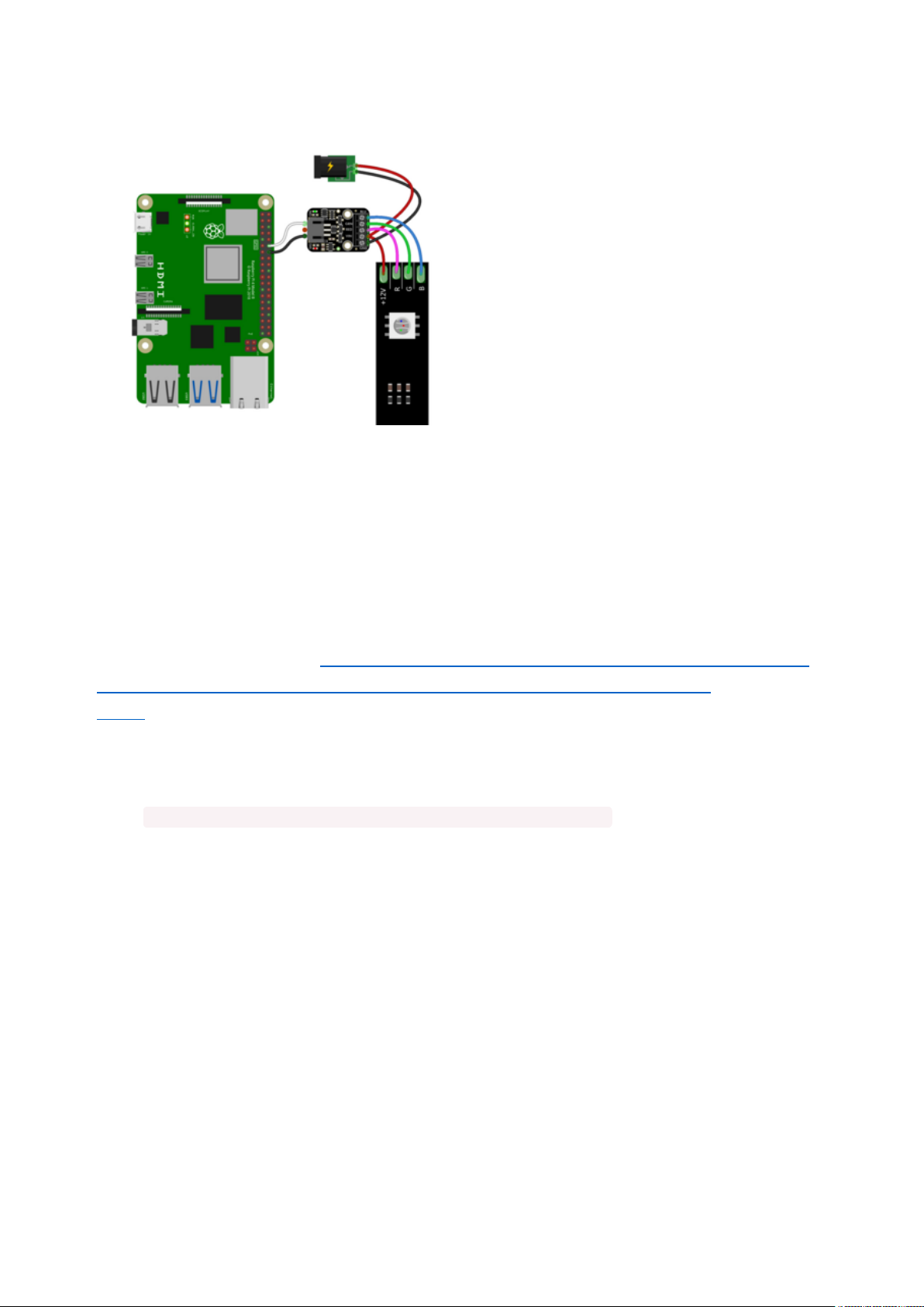
Pi GND to NeoRGB JST PH GND (black
wire)
Pi GPIO18 to NeoRGB JST PH SIG (white
wire)
Power supply positive pin to NeoRGB
terminal block VIN (red wire)
Power supply negative pin to NeoRGB
terminal block GND (black wire)
NeoRGB RED to RGB strip red channel
(pink wire)
NeoRGB GRN to RGB strip green channel
(green wire)
NeoRGB BLU to RGB strip blue channel
(blue wire)
NeoRGB VIN to RGB strip VIN (red wire)
Python Installation of NeoPixel Library
You'll need to install the Adafruit_Blinka library that provides the CircuitPython
support in Python. This may also require enabling I2C on your platform and verifying
you are running Python 3. Since each platform is a little different, and Linux changes
often, please visit the CircuitPython on Linux guide to get your computer
ready(https://adafru.it/BSN)!
Once that's done, from your command line run the following command:
pip3 install adafruit-circuitpython-neopixel
•
If your default Python is version 3 you may need to run 'pip' instead. Just make sure
you aren't trying to use CircuitPython on Python 2.x, it isn't supported!
CircuitPython Usage
To use with CircuitPython, you need to first install the
Adafruit_CircuitPython_NeoPixel library, and its dependencies, into the lib folder on
your CIRCUITPY drive. Then you need to update code.py with the example script.
Thankfully, we can do this in one go. In the example below, click the Download
Project Bundle button below to download the necessary libraries and the code.py file
©Adafruit Industries Page 11 of 25
Page 12

in a zip file. Extract the contents of the zip file, and copy the entire lib folder and the
code.py file to your CIRCUITPY drive.
Your CIRCUITPY/lib folder should contain the following files:
neopixel.mpy
•
adafruit_pixelbuf.mpy
•
Python Usage
Once you have the library pip3 installed on your computer, copy or download the
following example to your computer, and run the following, replacing code.py with
whatever you named the file:
python3 code.py
Example Code
If running CircuitPython: Once everything is saved to the CIRCUITPY drive, connect
to the serial console(https://adafru.it/Bec) to see the data printed out!
If running Python: The console output will appear wherever you are running Python.
# SPDX-FileCopyrightText: 2024 Liz Clark for Adafruit Industries
#
# SPDX-License-Identifier: MIT
import time
import board
from rainbowio import colorwheel
import neopixel
num_pixels = 1
# pylint: disable=simplifiable-condition
# check to see if its a raspberry pi
if "CE0" and "CE1" in dir(board): # pi only zone
pixel_pin = board.D18
# otherwise assume a microcontroller
©Adafruit Industries Page 12 of 25
Page 13
else:
pixel_pin = board.D5
pixels = neopixel.NeoPixel(pixel_pin, num_pixels)
color_offset = 0
while True:
for i in range(num_pixels):
rc_index = (i * 256 // num_pixels) + color_offset
pixels[i] = colorwheel(rc_index & 255)
pixels.show()
color_offset += 1
time.sleep(0.01)
The code has a check to determine if you are running the code on a Raspberry Pi or
not. If you are, the NeoPixel pin is set as GPIO18. Otherwise, the NeoPixel pin is set as
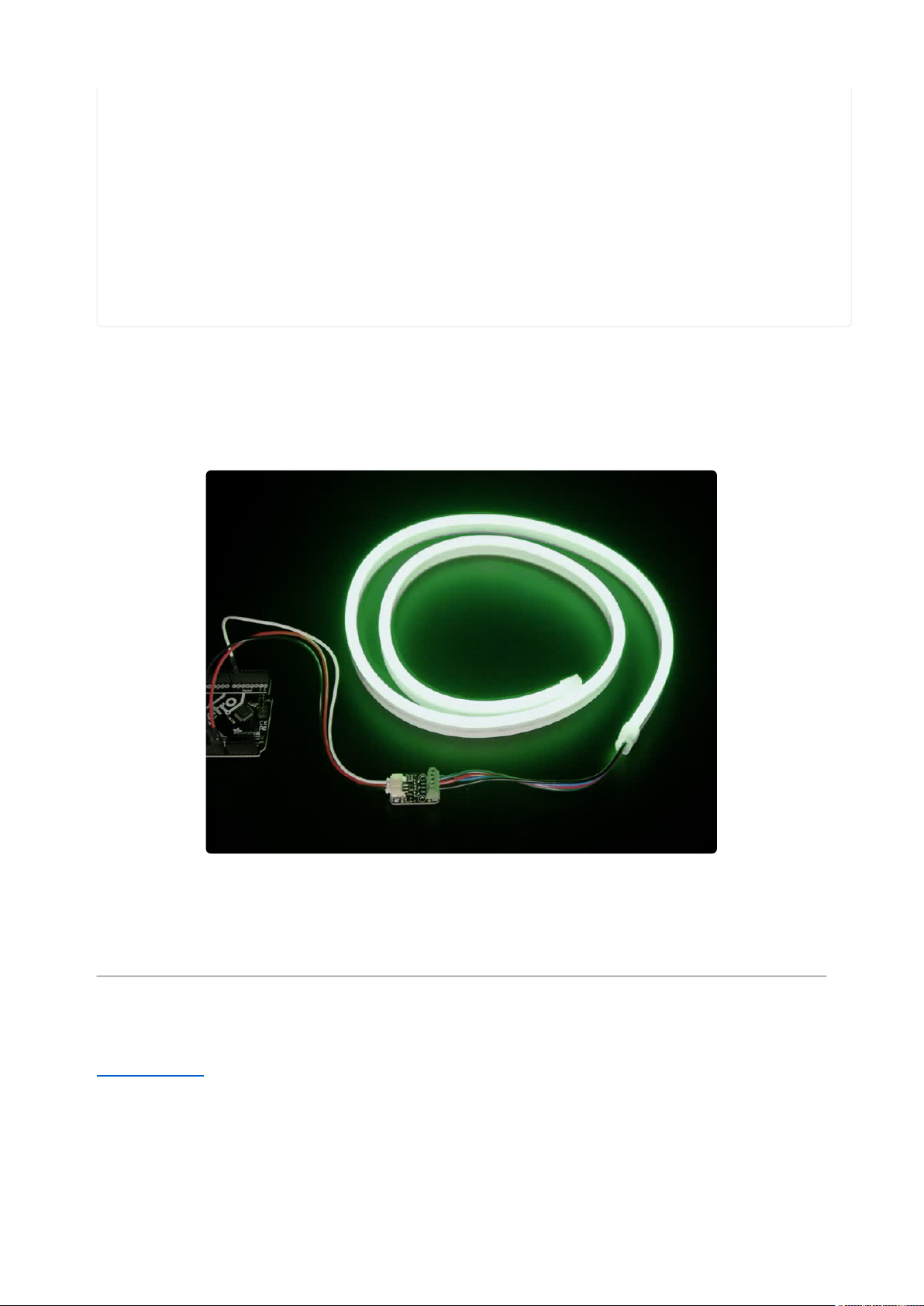
D5. Once the loop starts, you'll see your RGB LED(s) cycle through the colors of the
rainbow.
You should keep in mind when you write your own code that if you are using a strip,
all of the LEDs will act as one LED from a programming perspective since they aren't
individually addressable. That means some effects may look flashier or more abrupt.
Python Docs
Python Docs(https://adafru.it/18gA)
©Adafruit Industries Page 13 of 25
Page 14

Arduino
Using the NeoRGB Stemma with Arduino involves wiring up the breakout to your
Arduino-compatible microcontroller, installing the Adafruit_NeoPixel(https://adafru.it/
aZU) library and running the provided example code.
Wiring
Your wiring will differ depending on how many total amps will be used across all three
RGB channels. Here is how you'll wire the breakout to an Adafruit Metro and a single
RGB LED with less than 2A total used across all three RGB channels:
Metro 5V to NeoRGB JST PH VIN (red
wire)
Metro GND to NeoRGB JST PH GND
(black wire)
Metro pin 6to NeoRGB JST PH SIG (white
wire)
NeoRGB RED to RGB LED red anode (pink
wire)
NeoRGB GRN to RGB LED green anode
(green wire)
NeoRGB BLU to RGB LED blue anode
(blue wire)
NeoRGB GND to RGB LED cathode (black
wire)
Here is how you'll wire the breakout to an Adafruit Metro and a 12V RGB LED strip
with more than 2A total used across all three RGB channels:
©Adafruit Industries Page 14 of 25
Page 15

Library Installation
Metro GND to NeoRGB JST PH GND
(black wire)
Metro pin 6to NeoRGB JST PH SIG (white
wire)
Power supply positive pin to NeoRGB
terminal block VIN (red wire)
Power supply negative pin to NeoRGB
terminal block GND (black wire)
NeoRGB RED to RGB strip red channel
(pink wire)
NeoRGB GRN to RGB strip green channel
(green wire)
NeoRGB BLU to RGB strip blue channel
(blue wire)
NeoRGB VIN to RGB strip VIN (red wire)
You can install the Adafruit NeoPixel library for Arduino using the Library Manager in
the Arduino IDE.
Click the Manage Libraries... menu item, search for Adafruit NeoPixel, and select the
Adafruit NeoPixel library:
©Adafruit Industries Page 15 of 25
Page 16

There are no additional dependencies for the Adafruit NeoPixel library.
Example Code
// SPDX-FileCopyrightText: 2024 Limor Fried for Adafruit Industries
//
// SPDX-License-Identifier: MIT
#include <Adafruit_NeoPixel.h>
#ifdef __AVR__
#include <avr/power.h> // Required for 16 MHz Adafruit Trinket
#endif
// Which pin on the Arduino is connected to the NeoPixels?
// On a Trinket or Gemma we suggest changing this to 1:
#define LED_PIN 6
// How many NeoPixels are attached to the Arduino?
#define LED_COUNT 1
// Declare our NeoPixel strip object:
Adafruit_NeoPixel strip(LED_COUNT, LED_PIN, NEO_GRB + NEO_KHZ800);
// Argument 1 = Number of pixels in NeoPixel strip
// Argument 2 = Arduino pin number (most are valid)
// Argument 3 = Pixel type flags
void setup() {
// These lines are specifically to support the Adafruit Trinket 5V 16 MHz.
// Any other board, you can remove this part (but no harm leaving it):
#if defined(__AVR_ATtiny85__) && (F_CPU == 16000000)
clock_prescale_set(clock_div_1);
#endif
// END of Trinket-specific code.
strip.begin(); // INITIALIZE NeoPixel strip object (REQUIRED)
strip.show(); // Turn OFF all pixels ASAP
strip.setBrightness(50); // Set BRIGHTNESS to about 1/5 (max = 255)
}
void loop() {
rainbow(10); // Flowing rainbow cycle along the whole strip
}
// Rainbow cycle along whole strip. Pass delay time (in ms) between frames.
void rainbow(int wait) {
// Hue of first pixel runs 5 complete loops through the color wheel.
// Color wheel has a range of 65536 but it's OK if we roll over, so
// just count from 0 to 5*65536. Adding 256 to firstPixelHue each time
// means we'll make 5*65536/256 = 1280 passes through this loop:
for(long firstPixelHue = 0; firstPixelHue < 5*65536; firstPixelHue += 256) {
// strip.rainbow() can take a single argument (first pixel hue) or
// optionally a few extras: number of rainbow repetitions (default 1),
// saturation and value (brightness) (both 0-255, similar to the
// ColorHSV() function, default 255), and a true/false flag for whether
// to apply gamma correction to provide 'truer' colors (default true).
strip.rainbow(firstPixelHue);
// Above line is equivalent to:
// strip.rainbow(firstPixelHue, 1, 255, 255, true);
strip.show(); // Update strip with new contents
delay(wait); // Pause for a moment
}
}
©Adafruit Industries Page 16 of 25
Page 17

Upload the sketch to your board. You'll see your RGB LED(s) cycle through a rainbow
swirl animation.
You should keep in mind when you write your own code that if you are using a strip,
all of the LEDs will act as one LED from a programming perspective since they aren't
individually addressable. That means some effects may look flashier or more abrupt.
Arduino Docs
Arduino Docs(https://adafru.it/Etk)
WipperSnapper
©Adafruit Industries Page 17 of 25
Page 18

What is WipperSnapper
WipperSnapper is a firmware designed to turn any WiFi-capable board into an
Internet-of-Things device without programming a single line of code. WipperSnapper
connects to Adafruit IO(https://adafru.it/fsU), a webplatform designed (by
Adafruit!(https://adafru.it/Bo5)) to display, respond, and interact with your project's
data.
Simply load the WipperSnapper firmware onto your board, add credentials, and plug it
into power. Your board will automatically register itself with your Adafruit IO account.
From there, you can addcomponentsto your board such as buttons, switches,
potentiometers, sensors, and more! Components aredynamicallyadded to hardware,
so you canimmediately start interacting, logging, and streaming the data your
projects produce without writing code.
If you've never used WipperSnapper, click below to read through the quick start guide
before continuing.
Quickstart: Adafruit IO
WipperSnapper
https://adafru.it/Vfd
Wiring
First, wire up a NeoRGB Stemma component to your board following one of the
methods below, using a signal/data pin supporting PWM(https://adafru.it/19Fv) (see
the pinouts page on your board's learn guide).
Your wiring will differ depending on how many total amps will be used across all three
RGB channels (STEMMA / JST-PH connectors are rated(https://adafru.it/19Fw) for 2
Amps continuous load).
Here is how you'll wire the breakout to anAdafruit ESP32 Feather V2(http://adafru.it/
5400) using pin D14 and single RGB LED using less than 2A total used across all three
RGB channels.
©Adafruit Industries Page 18 of 25
Page 19

Feather 3V to NeoRGB JST PH VIN (red
wire)
Feather GND to NeoRGB JST PH GND
(black wire)
Feather pin 14 to NeoRGB JST PH SIG
(white wire)
NeoRGB RED to RGB LED red anode (pink
wire)
NeoRGB GRN to RGB LED green anode
(green wire)
NeoRGB BLU to RGB LED blue anode
(blue wire)
NeoRGB GND to RGB LED cathode (black
wire)
Here is how you'll wire the breakout to anAdafruit ESP32 Feather V2(http://adafru.it/
5400) using pin D14 and a 12V RGB LED strip with more than 2A total used across all
three RGB channels:
Feather GND to NeoRGB JST PH GND
(black wire)
Feather pin 14 to NeoRGB JST PH SIG
(white wire)
Power supply positive pin to NeoRGB
terminal block VIN (red wire)
Power supply negative pin to NeoRGB
terminal block GND (black wire)
NeoRGB RED to RGB strip red channel
(pink wire)
NeoRGB GRN to RGB strip green channel
(green wire)
NeoRGB BLU to RGB strip blue channel
(blue wire)
NeoRGB VIN to RGB strip VIN (red wire)
Usage
Connect your board to Adafruit IO Wippersnapper and navigate to the
WipperSnapper board list(https://adafru.it/TAu).
On this page, select the WipperSnapper board you're using to be brought to the
board's interface page.
©Adafruit Industries Page 19 of 25
Page 20
If you do not see your board listed here - you needto connect your board to Adafruit
IO(https://adafru.it/Vfd)first.
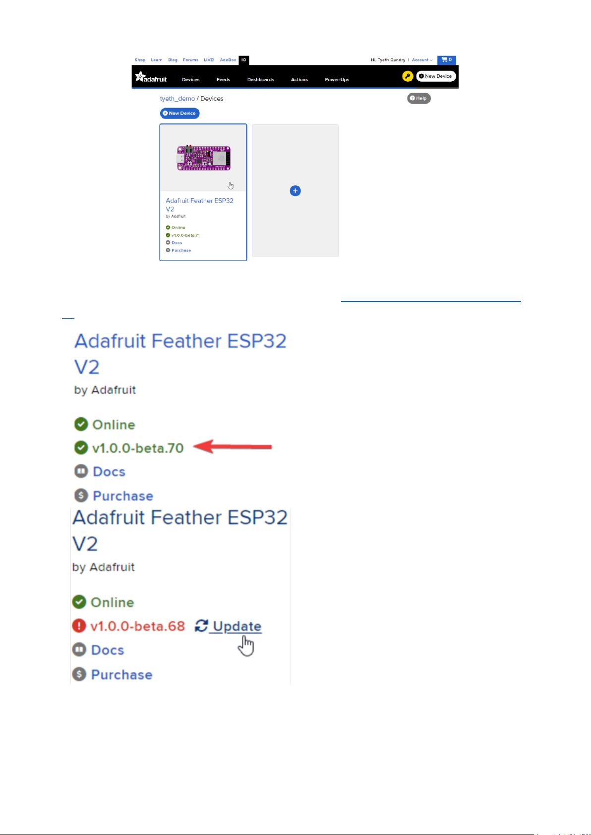
On the device page, quickly check that
you're running the latest version of the
WipperSnapper firmware.
The device tile on the left indicates the
version number of the firmware running on
the connected board.
If the firmware version is green with a
checkmark - continue with this guide.
If the firmware version is red with an
exclamation mark "!" - update to the latest
WipperSnapper firmware(https://adafru.it/
Vfd) on your board before continuing.
Next, make sure the component is plugged into your board, any external components
are correctly wired and powered, and then finally that your board is powered too.
Now you're ready to add your component to your WipperSnapper device.
©Adafruit Industries Page 20 of 25
Page 21
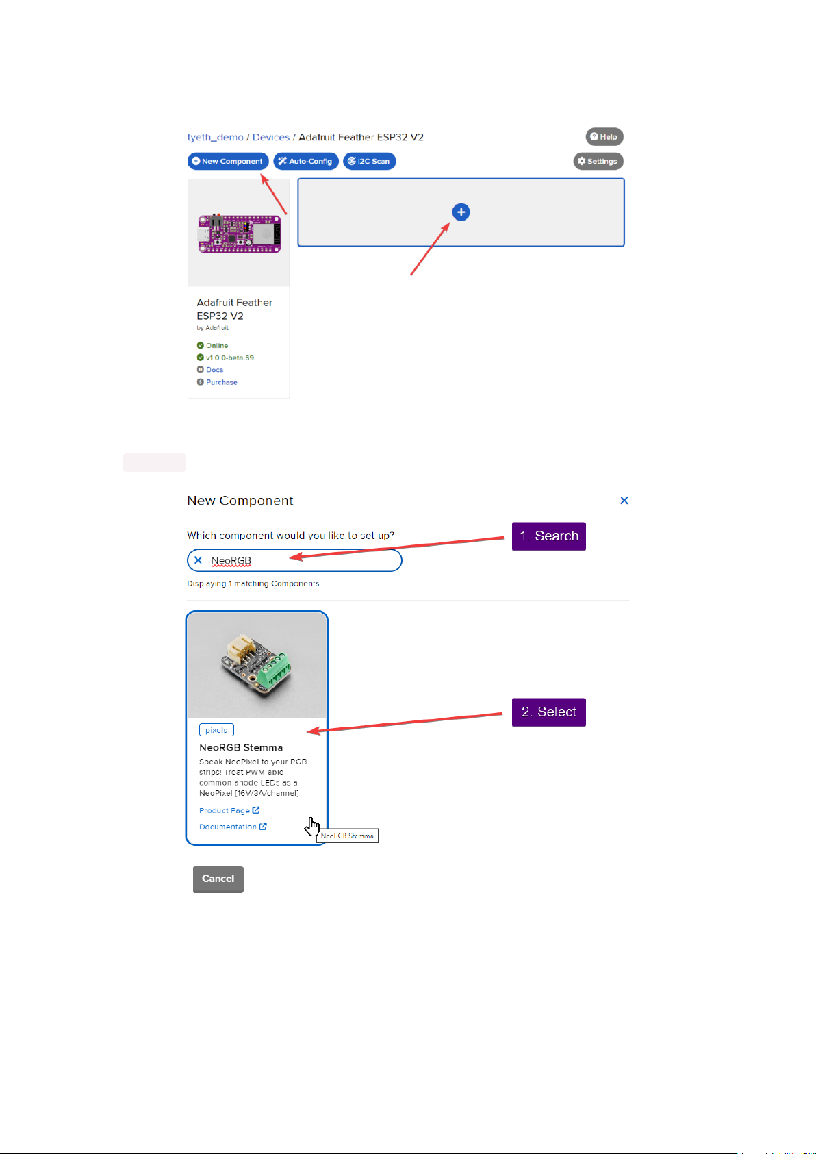
Click the New Component button or the + button to bring up the component picker.
Adafruit IO supports a large amount of components. To quickly find your sensor,
type NeoRGB into the search bar, then select the NeoRGB Stemma component.
On the component configuration page, the NeoRGB's component settings should be
listed. Select the NeoPixel Pin that has the NeoRGB / STEMMA signal wire attached
(D12 here), and leave Number of Pixels set to 1.
The Color Order option is specific to each RGB strip or your wiring. This option will
tell the Feather which signals to match up to Red / Green / Blue, and as a result for
©Adafruit Industries Page 21 of 25
Page 22

each color in the palette. Here the value is set to RGB as that matches the LED strip's
wiring.
Finally Brightnessis an overall maximum brightness for the LEDs, which can also be
useful to limit the current. This will be used to scale the components chosen color and
brightness via the Color Picker.
For this example, set the Brightness to 255, which is full brightness.
Your device interface should now show the NeoRGB component you created.
©Adafruit Industries Page 22 of 25
Page 23

Clicking one of the colors in the Color Picker, using the color dropper, and adjusting
the Brightness slider will cause WipperSnapper to automatically send Hexadecimal
color values to the component via Adafruit IO.
To view the data that has been previously sent to the component, click on the graph
next to the component name.
Here you can see the feed history and edit things about the feed such as the name,
privacy, webhooks associated with the feed and more. If you want to learn more
about how feeds work,check out this page(https://adafru.it/10aZ).
©Adafruit Industries Page 23 of 25
Page 24

Downloads
Files
WS2811 Datasheet(https://adafru.it/19fZ)
•
AO3406 N-channel FET Datasheet(https://adafru.it/19ga)
•
EagleCAD PCB files on GitHub(https://adafru.it/19gb)
•
Fritzing object in the Adafruit Fritzing Library(https://adafru.it/19gc)
•
©Adafruit Industries Page 24 of 25
Page 25

Schematic and Fab Print
©Adafruit Industries Page 25 of 25
 Loading...