


GG
XX
MM
SS
EE
RR
II
EE
SS
G
F
-
M
S
E
R
I
E
S
M
u
l
t
i
-
F
u
n
c
t
i
o
n
B
a
l
a
n
c
e
GX-M series
GF-M series
G
G
G
X
F
F
M
u
M
u
---M
-
M
-
M
i
t
l
i
t
l
INSTRUCTION MANUAL
-
-
F
F
u
u
n
n
S
S
S
c
t
i
c
t
i
E
E
E
o
o
n
n
R
R
B
B
R
a
l
a
a
l
a
I
I
I
n
n
E
E
E
c
e
c
e
S
S
S
GX-8202M / GX-8202MD / GX-10202M / GX-12001M
GX-22001M /GX-32001M / GX-32001MD
GF-8202M / GF-8202MD / GF-10202M / GF-12001M
GF-22001M / GF-32001M / GF-32001MD
1WMPD4003846

© 2020 A&D Company Ltd. All rights reserved.
No part of this publication may be reproduced, transmitted, transcribed, or translated
into any language in any form by any means without the written permission of A&D
Company Ltd.
The contents of this manual and the specifications of the instrument covered by this
manual are subject to change for improvement without notice.
Windows, Word and Excel are registered trademarks of the Microsoft Corporation.

Contents
1. Introduction .................................................................................................................... 6
1-1 Features ................................................................................................................................................. 6
1-2 About The Models .................................................................................................................................. 7
1-3 Compliance ............................................................................................................................................ 7
1-4 About Communication Manual ............................................................................................................... 8
2. Unpacking The Balance ................................................................................................. 9
2-1 Installing The Balance .......................................................................................................................... 10
3. Precautions ................................................................................................................... 11
3-1 Before Use.............................................................................................................................................11
3-2 During Use............................................................................................................................................ 12
3-3 After Use ............................................................................................................................................... 12
3-4 Power Supply ....................................................................................................................................... 13
4. Display Symbols And Key Operation ........................................................................... 14
4-1 Smart Range Function ......................................................................................................................... 16
5. Weighing Units ............................................................................................................. 17
5-1 Units ..................................................................................................................................................... 17
5-2 Storing Units ......................................................................................................................................... 22
6. Weighing ...................................................................................................................... 24
6-1 Basic Operation .................................................................................................................................... 24
6-2 Counting Mode(PCS) ...................................................................................................................... 26
6-3 Percent Mode (%) ................................................................................................................................ 28
6-4 Animal Weighing Mode(Hold Function) ........................................................................................... 29
7. Impact Detection Function ........................................................................................... 30
7-1 Recording Impact History ..................................................................................................................... 31
7-2 Output Impact History ........................................................................................................................... 31
8. Response Adjustment / Self Check Function ............................................................. 33
8-1 Response Adjustment .......................................................................................................................... 33
8-2 Self-Check-Function / Automatic Setting Of Minimum Weight Value ................................................... 34
9. Calibration .................................................................................................................... 36
9-1 Automatic Self Calibration For The GX-M Series ................................................................................... 37
9-2 One-Touch Calibration For The GX-M Series ...................................................................................... 38
9-3 Calibration Using An External Weight .................................................................................................. 39
9-4 Calibration Test Using An External Weight ........................................................................................... 40
9-5 How to set the External Weight Value .................................................................................................. 41
9-6 Correcting The Internal Mass Value Of The GX-M series .................................................................... 42
9-7 Correcting The Internal Mass Value Of The GX-M series (Auto) .............................................................. 43
10. Function Switch And Initialization ............................................................................... 44
10-1 Permit Or Inhibit ................................................................................................................................. 44
3

10-2 Initializing The Balance....................................................................................................................... 46
11. Function Table ............................................................................................................ 47
11-1 Setting The Function Table ................................................................................................................. 47
11-2 Details Of The Function Table ............................................................................................................ 49
11-3 Description Of The Class "Environment, Display" .............................................................................. 56
11-4 Description Of The Data Output ......................................................................................................... 57
11-5 Description Of The Data Format ......................................................................................................... 57
11-6 Output Example Of The Data Format ................................................................................................. 57
11-7 Clock And Calendar Function ............................................................................................................. 58
11-8 Comparator Function .......................................................................................................................... 60
11-9 Adding the Comparison Results ......................................................................................................... 66
11-10 Main Display Comparison Function .................................................................................................. 67
11-11 Description Of Application ................................................................................................................. 68
11-12 Outputting the function setting information ....................................................................................... 69
12. ID Number And GLP Report ....................................................................................... 72
12-1 Main Objective .................................................................................................................................... 72
12-2 Setting The ID Number ....................................................................................................................... 72
12-3 GLP Report ......................................................................................................................................... 74
13. Data Memory .............................................................................................................. 78
13-1 Data Memory For Weighing Data ....................................................................................................... 78
13-2 Data Memory For Calibration And Calibration Test ............................................................................ 82
13-3 Data Memory for Unit Mass in the Counting Mode ............................................................................ 85
13-4 Data Memory for Comparator Settings ............................................................................................... 88
13-5 Data Memory for Tare Value ............................................................................................................... 91
13-6 Data Memory: Quick Selection Mode ................................................................................................. 94
13-7 Data Memory: Confirmation and Storage Mode ................................................................................. 95
14. Statistical Calculation Mode ........................................................................................ 97
14-1 How To Use The Statistical Calculation .............................................................................................. 97
14-2 Statistical Calculation Mode (Example Of Use) ................................................................................ 102
15. Flow Measurement ................................................................................................... 104
15-1 How To Use Flow Measurement ...................................................................................................... 104
16. Gross Net Tare Function ........................................................................................... 108
16-1 Preparation Of Gross Net Tare Function .......................................................................................... 108
16-2 Example Of Using The Gross Net Tare Function ............................................................................. 110
17. Minimum Weighing W ar ning Function ...................................................................... 111
17-1 Comparing the minimum weighing value .......................................................................................... 111
17-2 Entering and outputting the minimum weighing value...................................................................... 112
18. Underhook ................................................................................................................ 117
19. Programmable-Unit .................................................................................................. 118
20. Density Measurement ............................................................................................... 119
4

21. Password Lock Function .......................................................................................... 124
21-1 Enable Password Lock Function ...................................................................................................... 125
21-2 How To Input The Password At The St art Of Weighing .................................................................... 126
21-3 How To Logout.................................................................................................................................. 127
21-4 Registering Password (Changing) ................................................................................................... 128
21-5 Changing Password ......................................................................................................................... 129
21-6 How To Delete The Password(U5ER 01~10) ................................................................................. 130
21-7 Missing Password ............................................................................................................................ 130
22. Repeatability Check Function (GX-M series only) ................................................. 131
23. Interface Specification(Standard) ........................................................................ 132
24. Maintenance ............................................................................................................ 132
24-1 Treatment Of The Balance. .............................................................................................................. 132
25. Troubleshooting ....................................................................................................... 133
25-1 Checking The Balance Performance And Environment ................................................................... 133
25-2 Error Codes ...................................................................................................................................... 134
25-3 Other Display .................................................................................................................................... 137
25-4 Asking For Repair ............................................................................................................................. 137
26. Connection With Periphecal Device ......................................................................... 138
26-1 Command ......................................................................................................................................... 138
26-2 Key Lock Function ............................................................................................................................ 138
27. How To Check The Software Version Of The Balance ............................................. 138
28. Specifications ........................................................................................................... 139
29. External Dimention ................................................................................................... 141
29-1 Options And Peripheral Instruments ................................................................................................ 142
5

1. Introduction
This manual describes how the GX-M/GF-M series balance works and how to get the most out of it in
terms of performance. Read this manual thoroughly before using the balance and keep it at hand for
future reference.
Depending on the softw are version of your balance, there are cases that behave differently.
For confirmation of the software version of the balance, refer to "27. How To Check The Software
Versi on Of The Balance".
1-1 Features
□ The balance has a self-ch eck function that inspects the balance itself using e l ec t r oni cally
controlled load (ECL) and evaluates performance. Read t his manual thoroughly before using the
balance and keep it at hand for fut ur e reference.
□ The balance can detect i m pact applied to its mass sensor and display the level of that impact .
ISD (Impact Shock Detection).
□ Continuous change of the balance can be calculated as flow rate, displayed and output. FRD :( Flow
Rate Display).
□ The b alance is equipped with a dat a memory function, which can r ecord weighing value,
calibration result, and mult iple unit mass (mass per sample in counting mode) (Up to 200 items
are stored for weighing value).
□ The GX-M series has automatic self c al ibration using the internal mass, adapting to temperat ur e
changes, setting time and interval time.
□ Good laboratory practice (GLP) / Good manufacturing practice (GMP) data can be output using
the RS-232C serial interfa ce.
□ A built-in clock and calendar that can add the time and date to the output data.
(Setting changes due to the clock can be limited only for an administrator. (Password Lock
Function))
□ Comparator Indicators, displaying the comparison results with
the setting, 5-step comparison is also possible.)
□ Capa city Indicator, displaying the weight value in percentage relative to the weighing capacity.
□ Hold Function, provided for weighing a moving object such as an animal.
□ Underhook, for me asuring density and weighing magnetic materials.
□ Password lock function can limit users for the balance to be used or changes due to the func tion
settings by setting a password.
□ Key lock func tio n all ows t he ba lan ce to only operate using commands from an external equipment
by disabling key operation s on the balance.
□ The balance is equipped with an RS-232C serial interface and a USB interface to communicate
with a computer. Windows computer using the Windows communication tools software (WinCT)
make building a system very easy. The latest Win-CT software can be downloaded from the A&D
website.
Windows is the registered trademark of the Microsoft Corporation.
□ A breeze break is included wit h t he m odel featuring a minimum display of 0.01g.
HI OK LO .(Depending on
6

1-2 About The Models
Model
Minimum
Applicable model
Internal mass type
General type
GX-8202M / GX-8202MD
GX-10202M
GF-8202M / GF-8202MD
GF-10202M
GX-12001M / GX-22001M
GX-32001M / GX-32001MD
GF-12001M / GF-22001M
GF-32001M / GF-32001MD
There are many models in the GX-M series and GF-M series with differences in the models being the
minimum display and weighing capacity. In this manual, they are listed collectively by the minimum
display as shown in the ta ble below.
display
0.01g model 0.01g
0.1g model 0.1g
□ For the GX-M series, a w eight for sensitivity adjustment is built in. It is possible to use functions
such as calibration and aut o cali br at i on using the internal mass.
□ For the GF-M series, sensitivity adjustment w eights are not built-in. When calibrating, it is
necessary to prepare an external weight.
1-3 Compliance
Compliance with FCC Rules
Please note that this equipment generates, uses and can radiate radio frequency energy. This
equipment has been tested and has been found to comply with the limits of a Class A computing
device pursuant to Subpart J of Part 15 of FCC rules. These rules are designed to provide
reasonable protection against interference when equipment is operated in a commercial
environment. If this unit is operated in a residential area, it may cause some interference and under
these circumstances the user would be required to take, at his own expense, whatever measures
are necessary to eliminate the interference.
(FCC = Federal Communi c at io ns C ommission in the U.S.A.)
7

1-4 About Communication Manual
About the contents of the communication, download "Communication manual" from our website
(https://www.aandd.jp/) and refer to it.
8

2. Unpacking The Balance
AX-TB248
Serial
Breeze beak provided for
Grounding
terminal
AC adapter plug
. The connection is tight
dustproof.
RS-232C terminals
(D-sub9 pin)
T er minal cov er
) to keep
waterproof and dustproof.
AC adapter jack
Draft gate
when cleaning.
Position of placing
AC adapter labels
Weighing pan
Bubble sprit level
Display
Keys
USB (mini-B)
Leveling foot
Pan support
A clear display cover
Handling hole
AC adapter plug
local voltage and receptacle type.
USB cable
The balance i s a prec isio n instru ment.
Unpack the balan ce careful ly. Keep the
packing materi al to be used for
transporting th e balance in the future.
The packing contents depend on the
balance mod el. See the ill ustratio ns to
confirm tha t every thing is contai ned.
Note
Cover the termin al or
connect the waterpro of
RS-232C cable
(AX-KO2737-500JA
Note
Please confirm that the AC
adapter type is correct for your
AC adapter labels
GX-8202M, GX-8202MD, GX-10202M,
GF-8202M, GF-8202MD, GF-10202M.
9
number
Remove the gate
Note
Insert t he plu g int o th e jack
firmly
to keep waterproof and
(approx. 1.8m)

2-1 Installing The Balance
3. Precautions
Bubble sprit level
Leveling foot
Grounding
T o AC adapter
Good No good
Install the balance as follows:
1 Refer to "
" for installing the balance.
2 Install the pan support, weighing pan and draft gate.
Refer to the previous page.
3 Adjust the leveling feet to level the balance.
Confirm it using the bubble spirit level.
4 Confirm that the AC adapter type is corre ct for the
local voltage and power receptacle type.
5 Connect the AC adapter to the balance firmly. Earth
the balance. Warm up the balance for at least 30
minutes with nothing on the weighing pan.
(Earth)
10

3.Precautions
To get the optimum performance from the balance and acquire accurate weighing data,
note the following:
3-1 Before Use
The maximum resolution of the precision balance is one million counts. Therefore, there are
tendencies to be influenced by temperature change, air pressure change, vibration and
drafts where the balance is placed.
Install the balance in an environment where the temperature and humidity are not
excessive. The best operating temperature is about 20°C / 68°F at about 50% relative
humidity.
Install the balance where it is not exposed to direct sunlight and it is not affected by heaters
or air conditioners.
Install the balance where it is free of dust.
Install the balance away from equipment that produces magnetic fields.
Install the balance in a stable place avoiding vibration and shock. Corners of rooms on the
first fl oor ar e best , as they ar e les s pr one to vi brat io n.
The w eighi ng tab le s houl d b e soli d a nd fr ee fr om vi br ati on, dr aft s an d as lev el as pos sibl e.
Level the balance by adjusting the leveling feet and confirm it using the bubble spirit level.
Ensure a stable power source when using the AC adapter.
Connect the AC adapter and warm up the balance for at least 30 minutes.
Cali brat e t he bal an ce per io dic ally for acc ura te wei gh ing .
When the balance is installed for the first time or has been moved, warm up the balance for
at least 6 hours to allow the balance to reach equilibrium with the ambient temperature, and
then perform calibration before use.
The meaning of IP-65 is "No ingress of dust. Projected against water jets".
If a powerful water jet is used or the balance is immersed in water, it may cause a damage
that is due to ingress of water.
Confirm that "the plug is inserted firmly into the jack" and "the terminal is covered using the
waterproof cover or the waterproof RS-232C cable (AX-KO2737-500JA)", when using the
balance.
Use the waterproof option cable AX-KO2737-500JA, when the RS-232C interface is used
with IP-65.
AX-KO2466-200, a st andard RS-232C cable, is not waterproof or dustproof.
Confirm that the weighing pan does not touch to rim.
Do not install the balance where flammable or corrosive gas is present.
11

3-2 During Use
Material case
Charged
Magnetic
40
20
Draft
Weighing Pan
Grounding
Shock
Discharge static electricity from the weighing material. When
weighing sample (plastics, insulator, etc.) could have a static
charge, the weighing value is influenced. Ground the balance, and
Eliminate the static electricity by AD-1683 as an accessory.
Or try to keep the ambient humidity above 45%RH at the room.
Or use the metal shield case.
Or wipe a charged material (plastic sample etc.) with the wet cloth.
This balance uses a strong magnet as part of the balance
assembly, so please use caution when weighing magnetic
materials such as iron. If there is a problem, use the underhook on
the bottom of the balance to suspend the material away f rom the
influence of the magnet.
sample
material
Eliminate any temperature difference between the samp le and the
environment. When a sample is warmer (coole r) than the amb ient
temperature, the sample will be lighter (heavier) than the true
°C
°C
weight. This error is due to a rising (falling) draft around the
sample.
Make each weighing gently and quickly to avoid errors due to
changes in the environmental conditions.
Do not drop things upon the weighing pan, or place a sample on
the pan that is beyond the balance weighing capacity. Place the
sample in the center of the weighing pan.
Do not use a sharp instrument such as a pencil to p ress the ke ys.
Use your fing er only .
Press the RE-ZERO key before each weighing to prevent
possible err ors.
Cali brat e t he bal an ce per io dic ally so as to el i minat e p ossi ble err ors .
Take into consideration the affect of air buoyancy on a sample
when more accuracy is required.
Prevent foreign matter, such as powder, liquid and metal, from invading the area around
the weighing pan.
3-3 After Use
Use t he "b reez e br eak " for a pr eci sio n weig hi ng.
Avoid mechanical shock to the balance.
Do not disassemble the balance. Contact the local A&D dealer if the balance needs service
or repair.
Do not use organic solvents to clean the balance. Clean the balance with a lint free cloth
that is moistened with warm water and a mild detergent.
12

Do not allow the balance to be immersed in wa ter. Even thou gh the ba lance comp lie s with
IP code, the balance will not withstand being completely immersed in water.
The weighing pan, pan support and draft gate can be removed to clean the ba lance. Clean
by spl as hi ng w it h w a ter .
3-4 Power Supply
Do not remove the AC adapter while the internal mass is in motion, for example, right
after the AC adapter is connected, or during calibration using the internal mass.
If the AC adapter is removed under the conditions described above, the internal mass
will be left unsecured, that may cause mechanical damage when the balance is
moved.
Before removing the AC adapter, press the ON:OFF key and confirm that zero is
displayed.
When the AC adapter is connected, the balance is in the standby mode if the standby
indicator is on. This is a normal state and does not harm the balance. For accurate
weighing, keep the AC adapter connected to the balance and AC power unless the
balance is not to be used for a long period of time.
13

S
t
a
b
i
l
i
z
a
t
i
o
n
i
n
d
i
c
a
t
or
Processing indicator
Response indicators
Standby indicator
Comparator indicators
Interval output mode
standby indicator
Number of statistical data
(Statistical calculation mode)
Displays the weight data relative to the
weighing capacity, in percentage, in the
weighing mode (Capacity indicator)
NET G PT
Preset tare mark
Gross mark
Net mark
USB connecting mark
Unit display
gross zero mark
Shock indicators
Animal weighing mark
Disiplay the measured value,
stored data, setting item name
4.Display Symbols And Key Operation
Blinking display contents
Processing indicator
Interal output mode
active indicator
Data number being displayed
Auto calibration notice
Blinking
Display symbols
14

Key operation
(for 2 seconds)
key during
operation will interrupt op er at ion and t ur n the display OFF. *
In the weighing mode, turns the minimum
Check Function". (GX -M s eries only)
erforms calibration of the balance using
ther items of the calibration
Stores the weighing data in memory or
sonal computer
depending on the function table settings.
Enters mode to change the unit mass
Outputs "Title block" and "End
Enters mode for reading density
Press and hold the key.
Press the key.
(Press and release the key immediately.)
Key operation af fe cts how the balance funct ions. The basic key oper at ions are:
“Press and release the key immediat ely” or “Press the key”
= normal key operation during me asur ement
“Press and hold the key”
(for 2 seconds)
Key When pressed
Turns the display ON:OFF . The standby indicator is displayed when the display is
turned off. The w ei ghing mode is enabled when t he display is turned on.
When password function is enable, password input display will be displayed. Refer to
"21-2 How to Input The Password At The S tart Of Weighing"
This ON:OFF key is available anytime. Pressing the ON:OFF
weighing value on and off.
In the counting or percent mode, enters the
sample storing mode.
Switches the weighing units stored in the
function table.
P
the internal mass. (GX-M series only)
Refer to "5. Weighing ".
When pressed and held
・Enters the function t able mode.
Please r efer to "1 1. Function Table".
・Run the repeatability check functi on.
Please refer to "22.Repeatability
Enters mode of the Self-Check
Function.
Displays o
menu.
outputs to a printer or per
(Factory setting = output)
Sets the display to zero.
* When the "Gross net tare function" is selected, the display is turned off by pressi ng and holding (for 2
seconds).
Please refer to "16.Gross Net Tare Function".
registration number in cou nt ing mode.
By changing the function table:
・
block" for GLP,GMP report.
・ Displays the data memory menu.
・
number in flow measurement.
15

(after RE-ZERO key is pressed
)
GX-32001MD
GF-32001MD
GX-8202MD
GF-8202MD
4-1 Smart Range Function
The GX-8202MD, GF-8202MD, GX-32001MD and GF-32001MD are equipped with two ranges of
"precision range" of a higher resolution and "standard range" of normal resolution.
The range is switched automatically depending on the value displayed.
Placing a heavy container on the weighing pan and pressing the RE-ZERO key allows the
balance to weigh in the pr ecision range. (Smart range fu nc t i on)
The range can be fixed to the standard range, by pressing the SAMPLE key.
Note
Once the range is switched to the standard range, it will not switch to the precision range
automatically even when the displayed value becomes within the precision range value. Press
the RE-ZERO or SAMPLE key to use the precision range again.
Example
GX-32001MD and GF-32001MD, precision range = 6.2 kg x 0.1g,
standard range = 32.2 kg x 1 g.
Step 1 Press the RE-ZERO key.
The balance will start weighing, using the
precision range.
Step 2 Place a container on the weighin g pan.
When the weighing value exceeds the
precision range, the range will be
switched to the standard range.
Step 3 Press the RE-ZERO key.
The balance will be switched to the precision
range.
Step 4 Place a sample on the pan.
When the weighing value is within the
precision range, the balance will perform a
weighing using the precision rang e.
Precision range/standard range value
Precision range
Weighing Pan
Precision range
Tare (Container)
Standard range
Precision range
Sample
Precision range
Standard range
g Up to 6200.9 g
g Up to 2200.09 g
16
6201 g to 32208 g
2200.1 g to 8200.8 g

5.Weighing Units
Function table
(Storing mode)
Conversion factor
1 g =
Gram
g
1 g
Counting mode
PCS
Percent mode
%
Ounce (Avoir)
OZ
28.349523125 g
Pound
Lb
453.59237 g
1 oz=28.349523125 g
Troy Ounce
OZt
31.1034768 g
Metric Carat
ct
0.2 g
Momme
mom
3.75 g
Pennyweight
dwt
1.55517384 g
Grain (UK)
GN
0.06479891 g
Tael (HK general, Singapore)
37.7994 g
Tael (HK jewelry)
37.429 g
Tael (Taiwan)
37.5 g
Tael (China)
31.25 g
Tola (India)
tol
11.6638038 g
Messghal
MES
4.6875 g
is used to
show the density.
Programmable-unit (Multi-unit)
MLT
p C 5 p C
5
t o 1
t o 1
g
OZ
L
PC
Pct OZ
Lb
OZt
ct
mom
dwt
GN
TL
MES
DS
Percent mode
Density mode (To use this mode, it must be stored in the function table as described on
page 15. For details about this mode, refer to "19. DENSITY MEASUREMENT".
To select this mode, press the MODE key until the processing indictor
blinks with the unit "g" displayed. "DS" appears only when the density
value is displayed.)
Programmable-unit (No unit displayed. For
details, refer to "18. PROGRAMMABLE-UNIT".)
Counting mode
tol
MLT
kg
“19.Programmable-Unit”.)
“20. Density Measurement”.
page 47.
5-1 Units
With the GX-M /GF-M series balance, the following weighing units and weighing modes ar e available :
A unit or mod e can be se lected and stored in the function table as desc r i bed on page 47.
If a weighing mode (or unit of weight) has been turned off, that mode or unit will be missing in the
sequence. Tael has four varieties, one of which ca n be selected and installed at the factory.
To select a unit or mode for weighing, press the MODE key.
For details about the units and modes, see the table below:
Name (unit, mode) Abbrev. Display
kilogram
kg 1000 g
Pound/Ounce L OZ l0 1Lb=16 oz,
TL
Density mode
(See note below)
DS
17

Note: The blinki ng processing i ndicator with “g” indicates that the dens i ty mode is selected.
GX-8202M
GF-8202M
GX-10202M
GF-10202M
minimum
display
The tables below indicate the weighing capacity and the minimum display for each unit,
depending on the balance model.
GX/GF-M
Unit Capacity Capacity
Gram g 8200 10200 0.01
Kiloram kg 8.20 10.2
Once(Avoir) oz 289 360
Pound Lb 18.1 22.5
0.00001
0.0005
0.00005
Pound/Once L oz 18L 1.2oz 22L 7.7oz 0.01
Troy Once Ozt 264 328
Metric Carat ct 41000 51000
Momme mom 2187 2720
Pennyweight dwt 5273 6559
Grain(UK) GN 126545 157410
0.0005
0.05
0.005
0.01
0.2
teal(HK general, Singapore) TL 217 270
Teal(HK jewely) TL 219 273
Teal(Taiwan) TL 219 272
Teal(China) TL 262 326
Tola(India) Tol 703 875
Messghal Mes 1749 2176
0.0005
0.0005
0.0005
0.0005
0.001
0.005
18

GX/GF-M
GX-12001M
GF-12001M
GX-22001M
GF-22001M
GX-32001M
GF-32001M
Minimum
display
Unit Capacity Capacity Capacity
Gram g 12200 22200 32200 0.1
Kiloram kg 12.2 22.20
Once(Avoir) oz 430 783
Pound Lb 26.9 48.9
32.20
1136
71.0
0.0001
0.005
0.0005
Pound/Once L oz 26L 14.3oz 48L 15oz 70L 15.8oz 0.01
Troy Once Ozt 392 714
Metric Carat ct 61000 111000
Momme mom 3253 5920
Pennyweight dwt 7845 14275
Grain(UK) GN 188275 342598
Teal(HK general, Singapore) TL 323 587
Teal(HK jewely) TL 326 593
Teal(Taiwan) TL 325 592
1035
161000
8587
20705
496922
852
860
859
0.005
0.5
0.05
0.1
2
0.005
0.005
0.005
Teal(China) TL 390 710
Tola(India) Tol 1046 1903
Messghal Mes 2603 4736
1030
2761
6869
0.005
0.01
0.05
19

GX/GF-M
GX-8202MD
GF-8202MD
Standard range
Precision range
Minimum
display
Minimum
display
Unit Capacity
Capacity
Gram g 8200 0.1 2200 0.01
Kiloram kg 8.20 0.0001 2.20 0.0001
Once(Avoir) oz 289 0.005 77.6 0.0005
Pound Lb 18.1 0.0005 4.85 0.00005
Pound/Once L oz 18L 1.2oz 0.01 4L 13.6oz 0.001
Troy Once Ozt 264 0.005 70.7 0.0005
Metric Carat ct 41000 0.5 11000 0.05
Momme mom 2187 0.05 587 0.005
Pennyweight dwt 5273 0.1 1415 0.01
Grain(UK) GN 126545 2 33951 0.2
teal(HK general, Singapore) TL 217 0.005 58.2 0.0005
Teal(HK jewely) TL 219 0.005 58.8 0.0005
Teal(Taiwan) TL 219 0.005 58.7 0.0005
Teal(China) TL 262 0.005 70.4 0.0005
Tola(India) Tol 703 0.01 189 0.001
Messghal Mes 1749 0.05 469 0.005
20

GX/GF-M
GX-32001MD
GF-32001MD
Standard range
Precision range
Minimum
display
Minimum
display
mo
m
Unit
Capacity
Capacity
Gram g 32200 1 6200 0.1
Kiloram kg 32.2 0.001 6.20
Once(Avoir) oz 1136 0.05 219
Pound Lb 71.0 0.005 13.7
0.0001
0.005
0.0005
Pound/Once L oz 70L 15oz 0.1 13L 10.6oz 0.01
Troy Once Ozt 1035 0.05 199
Metric Carat ct 161000 5 31000
Momme
8587 0.5 1653
Pennyweight dwt 20705 1 3987
0.005
0.5
0.05
0.1
Grain(UK) GN 496922 - 95681 teal(HK general, Singapore) TL 852 0.05 164
Teal(HK jewely) TL 860 0.05 165.6
Teal(Taiwan) TL 859 0.05 165.3
Teal(China) TL 1030 0.05 198.4
Tola(India) Tol 2761 0.1 532
Messghal Mes 6869 0.5 1323
0.005
0.005
0.005
0.005
0.01
0.05
21

5-2 Storing Units
Press
several times
Select
Specify
Store
Displays the units
sequentially.
The units or modes can be selected and stored in the function table. The sequence of displaying the
units or modes can be arrange d t o fit t he frequency of use.
The units stored are ma intained in non-volatil e memory, even if the AC adapter is rem oved.
Select a unit or mode and arr ange the sequence of display as follows:
1. Press and hold the SAMPLE key (for 2 seconds) until
ba5fnc of the function table is displayed, then release
the key.
2. Press the SAMPLE key several times to display
1Unit .
3. Press the PRINT key to enter the unit selection
mode.
4. Specify a unit or mode in the order to be displayed using
SAMPLE key To sequentially display the units.
5. Press the PRINT key to store the units or modes. T he
6. Press the CAL key to exit the function table. Then the
7. To select other unit or mode for w eighing, press the MODE key.
the following keys.
RE-ZERO key To specify a unit or mode. The
stabilization indicator
appears when the displayed unit or
mode is specified.
If the key is pressed in units already
selected, the stability mar k d isa ppears.
balance displays end and then displays the next menu
of the function table.
balance returns to the weighing mode with the selected unit.
22

Specify
Select
Store
Specify
Pr
es
s
severa
l
t
i
me
s
Pr
es
s
a
nd
ho
l
d
(for 2 seconds)
Unit setting example
The example below sets the units in the order with g (gram) as the first unit followed by pcs
(counting mode).
1. Press and hold the SAMPLE key (for 2 seconds) until
ba5fnc of the function table is displayed, then
release the key.
2. Press the SAMPLE key several times to display
1Unit .
3. Press the PRINT key to enter the unit selection
mode.
4. Press the RE-ZERO key to specify the unit of g
The stabilization indicator appears when the
unit is specified.
5. Press the SAMPLE key to display 1Unit pC5 .
6. Press the RE-ZERO key to specify the unit of pcs.
The stabilization indicator appears when the
unit is specified.
7. Press the PRINT key to store the units.
The balance displays end and then displays the next
menu item of the function table.
8. Press the CAL key to exit the function table. Then
the balance returns to the weighing mode with g, the
unit selected first.
9. Press the MODE key to switch between g and pcs
(g→pcs).
23

6.Weighing
Weighing
pan
Container
(Display off)
Weighi
n
g
pan
Co
n
tai
n
e
r
Sample
R
e
move
th
e
sa
mp
le
6-1 Basic Operation
1. Press MODE key, and then select t he appropriates units
In this case, select " ".
2. Place a container on the weighing pan, if necessary.
Press the RE-ZERO key to cancel the weight (tare).
The balance displays 0.00 g. (The decimal point position
depends on the balance mo del.)
3. Place a sample on the pan or in the container. Wait for the stabilization
indicator
to be display ed. Read t he value.
Remove the sample and c ontainer from the pa n.
Note
□
Press the SAMPLE key to turn on or off the minimum weighing value.
□ The weighing data can be stored in memory. For details, refer to “13.
Data Memory”.
When the ON:OFF key is pressed w it h a container placed
□
on the weighing pan and weigh in g is st ar t ed, the balance
automatically cancels t he weight (tare) and display s 0.00 g.
24

About the operation at when power is turned on
Power on zero
range
GX-8202M,
GF-8202M
Approx.±160g
GX-8202MD,
GF-8202MD
Approx.±160g
GX-10202M,
GF-10202M
Approx.±200g
GX-12001M,
GF-12001M
Approx.±200g
GX-22001M,
GF-22001M
Approx.±400g
GX-32001M,
GF-32001M
Approx.±600g
GX-32001MD,
GF-32001MD
Approx.±600g
The balance will decide the r eference zero point when the pow er i s turned on (AC adapter is
connected).
Depending on the load co ndition at that time, it will automati c ally judge whether to perform z er o or tare
operation. The condition for determining whic h is u sed is "power on zero range" , and w hen power on
zero range is exceeded, the tare subtraction operat ion is performed.
About re-zero operation
By pressing the RE-ZERO key, the dis pl ay can be changed to zero.
Re-zero with the RE-ZERO key will automatically determine whether zero or tare operation is
performed.
The condition for determin ing which is used is "zero range", and when zero range is exceeded, the tare
subtraction operation is p er formed.
About measurement range
For the balance, the range t hat can be w eighed is determined by model.
The total amount (net amount + tare quantity) up to the maximum display of each model is displayed,
and when the maximum display is exceeded, E is displayed to indicate that the weighing range is
exceeded.
When in excess in negative, -E is displayed.
Model
Approx.±1kg
Approx.±3kg
Zero range -E displ ay range
Approx.-1kg or less
Approx.-3kg or less
25

6-2 Counting Mode(PCS)
lo
Weighing pan
Container
Sample
(25 pieces)
(The couting result)
place
This is the mode to determine the number of objects in a sample based on the standard sample unit
mass. Unit mass means the mass of one sample. The smaller the variables in each sa mp le un it ma ss
is, the more accurate the counting will be. This series balance is equipped with the Automatic
Counting Accuracy Improv em ent ( ACAI) function to improve t he counting accuracy.
Note
* For counting, use samples that have a unit mass at least ten times greater than that of the
minimum display in grams.
* If the sample unit m ass variable is too large, it may cause a counting error.
* To improve the counting performance, use the ACAI function frequently or divide the samples
into several groups an d count each group.
Selecting the counting mode
1. Press the MODE key to select pC5 ( pC5 = unit)
Storing a sample unit mass
2. Press the SAMPLE key to enter the sample unit mass
storing mode.
3. To select the number of samples, press the SAMPLE key
several times. It may be set t o 5, 10, 25, 50 or 100.
Note
A great er number of samples will yield more accurate counting result.
Place a container on the weighing pan, if necessary .
Press the RE-ZERO key to cancel the weight (tare). The number
specified in step 3 appear s.
25 0 is displayed if 25 is selected in "3".
4. Place the number of samples specified on the pan. In this example, 25
pieces.
5. When PRINT key pressed, unit mass is stored and changes the
count display. (Ex: when the number is 25, 25 pC5 is displayed.
Note
* If the balance judges that the mass of the samples is too light to
acquire accurate weighing, it displays an error requiring the addition
of more samples to the specified number and press the PRINT..
key. When the unit mass is stored correctly, the balance proceeds to
the counting mode.
* I f the balance judges that the mass of the samples is too light and
* Registered unit mass is remembered even when the power is turned off.
Number mode(counting)
6. Counting is possible.
is not adequate to be used as the unit mass, it displays
26
.

Processing mark
Counting Mode Using The ACAI Function
Press and hold
+1
The ACAI is a function that improves the accuracy of the unit mass automatically by increasing the
number of samples as the counting process.
ACAI: Automatic Counting Accuracy Improvement
After registering un it ma ss of "5", proceed to the following "7".
7. If a few more sam ples are added, the processing indic ator turns on. To
prevent an error, add three or more . The processing indicator does not
turn on if overloaded. Try to add the same number of samples as
displayed.
8. The balance re-calculates the u nit mass while the proc essing i ndicato r is blink ing . D o not touch
the balance or samples on the pan until the processing indicator turns off.
9. Counting accuracy is improved when the processing indicator turns off.
10. Each time the above operation is perf o rm ed, a more accurate unit mass will be obtained. There
is no definite upper limit of ACAI range for the number of samples exceeding 100. Try to add the
same number of samples as displayed.
11. Remove all the samples used in ACAI and proceed with the counting operation using the
improved unit mass.
Note ACAI will not function on the unit mass entered using the keys, or digital input mode.
Storing the unit mass
By using the data me m or y function, 50 instances of storing a
sample unit mass can be st or ed.
1. Set the function s et t ing item "Data memory function ( ) " to "Stores unit mass in counting ( ) " .Refer to "11.Function Table".
2. The displayed
number.
3. Press and hold the PRINT key (for 2 seconds) to switch to the
mode to change the unit mass r egistration number.
RE-ZERO key ············ Changes the registrat ion number(+)
MODE key ··············· Changes the registration number (-)
PRINT key ··············· Decides on the displayed registration number.
CAL key ··················· Cancel the displayed registration num ber.
4. Multiple unit masses can be stored by registering them with different unit mass registration numbers.
Note
*
p **: The unit weight registr at ion number is entered.
* Unit weight can be read by ″ UN:mm ″ command.
(mm corresponds to P01 to P50 with 01 t o 50.)
* The read unit mass can output by ″ ?UW ″ command and can be changed by ″ UW ″
command.
" p ** " is the selected unit mass registration
(for 2 seconds)
-
1
Note
* ACAI cannot be used for the read unit mass.
27

6-3 Percent Mode (%)
Model
100% mass
Decimal point position
Minimum display 0.01g
1.00g ~ 9.99g
1%
10.00g ~ 99.99g
0.1%
100.00g ~
0.01%
Minimum display 0.1g
10.0g ~ 99.9g
1%
100.0g ~ 999.9g
0.1%
1000.0g ~
0.01%
place
Display % of weighing object
Weighing
pa
n
C
on
t
ainer
Sample
(100%)
The percent mode displays the weighting value in percentage compared to a 100%
reference mass and is used for target weighing or checking the sample variance.
Selecting The Percent Mode
1. Press the MODE key to select the unit % (Percent mode).
Storing The 100% Reference Mass
2. Press the SAMPLE key to enter the 100% reference
mass storing mode.
Even in the storing mode, pressing the MODE key will
switch to the next mode.
3. Place a container on the weighing pan, if necessary. Press the RE-ZERO
key to cancel the weight (tare). The balanc e di splays 100 0 % .
4. Place the sample to be set as the 100% reference mass on the pan or in
the container.
5. Press the PRINT key to store the reference mass.
The balance displays 100.00 %. (The decimal point
position depends on the refer ence value. The reference
mass stored, even if the AC adapt er is r emoved, is
maintained in non-volat ile memor y. )
Note
□
If the balance judges that the mass of the sample is too light to be
used as a reference, it display s
□ The displayed percentage is based on the 100% re f er ence mass.
□ Registered value s are s t ored even when the power is turned off.
6. Remove the sample
Reading the percentage
7. Please a sample to be co m pared to the reference mass on the pan.
The displayed percentage is based on the 100% reference m ass.
lo .
28

6-4 Animal Weighing Mode(Hold Function)
This is the mode to weigh a mov i ng object such as an animal, even w hen t he display of the weighing
data fluctuates. The hold f unct ion allows the average weight of the animal to be displayed. To use
the hold function, set the funct ion in the function table. Refer to " 11. Function Table" and "11-3.
Description Of The Class " Environment, Display" for details.
29

7. Impact Detection Function
Impact level
Shock indicator
Buzzer
Contents
0
Safe
1
Caution
2
Caution:Consider impact mit igation
3
Warning:Do not apply greater impact
4
Danger:Sensor may be damaged
The GX-M / GF-M series has a function to detect impact to the mass sensor section and to display
the impact level.
By lowering the impact level at the time of loading, it is possible not only to alleviate variation in the
weighing value but also to r educ e t he r isk of failure of the mass sen sor section.
Especially when incorporating the balance in a production line, etc. and weighing by means such as
an automated system, impact to the sensor may be applied greater than expected.
When designing automatic systems and the like, it is recommended that you minimize the impact
level as much as possible while checking the shock indicat or.
Impact level display is from level 0 to level 4, 5level.
No
SHOCK
SHOCK
SHOCK
SHOCK
No
No
No
One
beep
Two
beep
Note
□ Impact on the weighing sensor may be applied to the weighing pan at time of loading, or it may be
applied from the table on which the balance is inst alled.
The impact detection f unction also works for impac t applied from the table.
30

7-1 Recording Impact History
Press and Hold
Press
Output
(for 2 seconds)
Impacts of impact level 3 or higher are stored on the balance with data and time included (maximum
50 data instanc es) .
When the password lock function is on (LOcK 1 or Lock2 ), the login user inf ormation is added when
outputting the impact history.
Note
□ If 50 data instances is exceeded, the data with the lowest impact level is over w r itten.
□ The stored impact history cannot be deleted.
□ Impact data where the balance is not energized (during transport, etc.) is not stored.
7-2 Output Impact History
The stored impact history can be output by sending a specified command to the balance or performing
a key operation.
Output by command
The stored impact data will be output al l at once by sending a ?SA command to the balanc e.
Output by key oper a t ion
1. Press the ON:OFF key to turn off the display.
2. With the display off, press the ON:OFF key
while holding down the MODE key.
3. is displayed, and t he st or ed impact
data is output all at once.
31

Impact history output example
Output
Login user
Function table LOcK
, --,
No login user
,00, ADMIN
Administrator
,01~10,USER
User
1
, --,GUEST
Guest
Date, time, impact level, login and log in user information are output toget her on one line.
The login user information varies by the setting of the login user and the setting of Function table
LOcK when receiving impact.
0, 1, 2
1
2
Output example
2018/05/29,11:08:18,SHOCK LV,3, --,
2018/05/29,11:12:27,SHOCK LV,4,00,ADMIN
2018/05/29,11:13:38,SHOCK LV,3,01,USER
2018/05/29,11:17:04,SHOCK LV,4, -- ,GUEST
32

8. Response Adjustment / Self Check Function
setting
FAST
Cond 0
Slow response, Stable value
MID.
Cond 1
SLOW
Cond 2
Display
Cond (Condition)
5pd (Display refresh rat e)
5t-b (Stability bad width)
FAST
0 2 2
MID.
1 0 1
SLOW
2 0 1
Response
indicator
Press and H
old
R
el
e
ase
and
press again
Each pressing switches
the indicators
After a while
(for 2 seconds)
This function stabilizes the weight value, reducing the influence on weighing that is caused by drafts and/or
vibration at the place where the balance is installed. This function adjusts by automatically analyzing the
environment or by hand-operation. The function has three stages as follows : Changing the weighing speed
changes the display refresh rate.
Display
Function
8-1 Response Adjustment
Response adjustment can be changed by the following met hod.
1. Press and hold the MODE key (for 2 seconds) until
RESPONSE is displayed, and then release the key .
2. Pr ess t he MODE key to select a weighing speed.
Response characterist ic
Fast response, Sensitive value
Either FAST , MID or SLOW can be selected.
3. After a few seconds of inactivity the balance displays end .
4. Then, it returns to the weighing mode and displays the
updated response indicator .
The response indicator remains displayed for a while.
Note
When setting the Response adjustment, "Condition Cond" and
"Display refresh rate 5pd" in the 11.Function T able "Environment
display ba5fnc" are changed as below.
When using a combination other than the above, please set individually as shown in "11. Function Table".
Note
If RESPONSE is displayed and you leave without pressing the MODE key,
the "Self-check function" is activated. Please refer to "8-2. Self-Check-Function /
Automatic Setting Of Min i mu m Weight Value ".
For the setting method, refer to "11.Function Table".
33

8-2 Self-Check-Function / Automatic Setting Of Minimum
4. Display shows a check result after check. When ther e is n o er r or in t he balance, display shows
ECL
Weight Value
The self-check func tion can easi ly check abou t whether proper performances are satisfied for the balance by
checking and displaying repeatability in addition to malfunction check.
In addition, it can also display and store minimum weighing value (reference value) using data of the
repeatability.
Refer to “Balance information” on the A&D web site <http://www.aandd.co.jp/> for details of the minimum
weighing value.
Setting procedure (Together refer to setting flow chart on next page.)
1. Press and hold the MODE key (for 2 seconds) in weighing mode.
2. Release the key after displaying RESPONSE .
3. Display shows and self-chec k function is started. After few seconds, display shows“ECL”. Press the MODE key while is di splayed to observe changes in the weighing value of the repeatability using electronic control load (ECL).
in blinking. When display shows in blinking, there is a possibility that
serious malfunctions occurs in the balance. In such case, t he balance requires repa ir.
SAMPLE key…
PRINT key……Outputs c ur rently displayed contents
MODE key……
Use the following keys while the minimum weighing value (reference value) is displayed to perform
each operation.
5. Outputting data of the minimum weighing value at once
Press and hold the PRINT key (for 2 sec onds) to display Out . After outputting at once,
is displayed.
Switches a display among check result, repeatability and minimum weighing
value (reference value).
At repeatability display, display shows “OK” if it is satisfied for cat al og spec.
However, if it is not satisfied for catalog spec, display requests an
improvement in an environment for the balance installed by blinking “Env”
Switches an allowable measurement error of the minimum weighing value
(reference value).
6. Storin g as minimum weighing value ( r eference value) of “17. Minimum Weighing Warning Function”
Press and hold the SAMPLE key (for 2 seconds) to dislay MW 5Et . Minimum weighing value
(reference value) is store d. Af t er st or ing, display shows and returns to weighin g m ode.
7. When not storing
Press the CAL key to return to weighing mode after disp laying .
34

8. To return to check result display
ECL
4.82
1
Weighing value change in
repeatability
ECL
Press and hold (for 2 seconds)
Release
FAiL
Few seconds later
[
[
REF
REF
OK
4.8
12.3
Env
REF
REF
REF
Normal
Improve the
when
is set to
the balance automatically
Go
Press and ho l d (for 2 seconds )
Batch
Press and hold (for 2 seconds)
Store
minimum weighing value
GX-10202M
Press the SAMPLE key to return to check result display in Step 4.
* Refer to “17. Minimum Weig hing W arning Functio n” for warni ng f unc tion of minimum weighing value.
Setting flow chart
①
Output
Output
Output
Check result]
Repair is required
performance
0_1 %
MW 9.60
0.00
5D
②
③
Check result]
1 %
MW 0.96
Normal
④
0_1 %
MW 54.60
5D
environment installed
MW 5.46
1 %
0.0057 g
output
⑤
Out
End
⑥
⑦
⑧
MW 5ET
MW-CP
set it to
1
(except near zero) and enables comparing
function of the minimum weighing value.
0,
End
0.00
35

9.Calibration
Since the balance's resolu tion is high, weighing values may change due to gravity and daily
environmental cha nges. It is necessary to perform c ali br at i on ( sensitivity adjustment) w ith the
weight in order to keep the weigh in g values from changing even if grav it y or the environment
changes.
It is recommended that you calibrate if the balanc e is installed for the first t ime or relocated, or
when the weighing values change significantly in daily inspection, etc.
Adjustment means to adju st the weighing value of the balance using the reference weight or
internal mass. Calibrati on is to weigh with the reference weight and compare how much the result
deviates from the referen ce value. (Adjustment is not performed in calibration.)
Calibration (Sensitivity adjustment)
Auto calibration·········································· Automatically adjust the balance using the internal
mass depending on the temperature change of the
operating environment or the set time and interval
time.(GX-M series)
Calibration using the inter nal mass ················ Using the internal mass, adjust the balance with a
single touch.
Calibration using an external weight··············· Using an external mass, adjust the balance with an
external mass.
Calibration test(Sensitivity calibration)
Calibration test with an external weight ··········· Output the result of checking the accuracy of
weighing using your own w eight .
* No adjustment is ma de.
Caution
□ Do not allow vibration or drafts to affect the balance during ca li br at ion.
□ To output the data for GLP/GMP using the RS-232C interface, set "GLP/GMP output (info)" of
"Data output (dout)". Refer to "11. Funct ion Table". The time and date can be added to the
GLP/GMP report. If the time or date is not correct, adjust them. Refer to "11-7 Clock and Calendar
Function".
□ The calibration and calibration test data can be stored in memory. To store them, set "Data memory
(data)" .
Caution when using your external weight
□ The accuracy of the weight used in calibration af fects the accuracy of t he balance after calibrat io n.
□ Select the mass to be used for calibration and calibration tests from the table below.
36
Model Usable calibration weight
Factory
setting
Adjustable
range
GX-8202M,
GF-8202M
2kg to 8kg (1kg interval)
5kg
GX-8202MD,
GF-8202MD
2kg to 8kg (1kg interval)
5kg
GX-10202M,
GF-10202M
2kg to 10kg (1kg interval)
10kg
GX-12001M,
GF-12001M
5kg,
10kg
10kg
GX-22001M,
GF-22001M
5kg,
10kg,
20kg
20kg
GX-32001M,
GF-32001M
5kg,
10kg,
20kg, 30kg
20kg
GX-32001MD,
GF-32001MD
5kg,
10kg,
20kg, 30kg
20kg
CFnc 0
CFnc 1
CFnc 3
CFnc
0.01g models
0.1g models
More than 20g
More than 200g
-99.99g to
+99.99g
-999.9g to
+999.9g
Display
This indicator means "I n pr ocess of measuring calibrat ion d ata".
Do not allow vibration or drafts to affect the balance while the in dicat or i s
displayed.
9-1 Automatic Self Calibration For The GX-M Series
This function automatically calibrates the balance using the internal weight due to a temperature
change in the ambient environment, time set or interval time. It can function even when the balance’s
display is in off. If GLP output in function table is selected, the balance outputs the sensitivity
adjustment report or st ore th e dat a in memo ry after calibratio n.
In the auto calibration mode, either the temperature change (
interval time (
For the setting time, the three function setting of , and can be set.
) can be set with the functi on setting
.
), the setting time (
), or the
Interval time can be set from 0.5h to 24h with function setting .
Caution
If something is on the weighing pan , the balan ce judg es that i t is in use an d doe s not perfo rm automatic
self calibration.
The criteria that the balance judges is in use are as follows.
To maintain the calibrated state, keep the weighing pan clear while not in use.
Indicates that the balance det ects a change in ambient t emp er at ur e and
automatic self calibration will start. If the balance is not used for a few
minutes with this indicator ( ) blinking, the balance performs automatic self
calibration. The blinking duration depends on the environment.
Indicates that the balance is measuring calibration data. Do not allow
vibration or drafts to affect t he bala nce while this indicator is disp lay ed. After
calibration, the balance returns to indicate the previous display.
Note The balance can be used while the indicator blin ks. But, it is recommended that to
maintain the accuracy, stop using the balance and confirm that ther e is nothing on the pan
and allow the balance to perform self calibration.
Depending on the setting of "10.Function Switch And Initializat i on" , " change prohibited" or
"changeable (usable) " can be selected.
37

9-2 One-Touch Calibration For The GX-M Series
This function calibrates the balance using the internal mass.
1. Connect the AC adapter and warm up the balance for at least 30 minutes with nothing on the
weighing pan.
2. Press the CAL key. The balance displays Calin and performs calibration using the internal
mass. Do not allow vibration or drafts to affect the balance.
3. The balance displays end after ca librat ion. If the " GLP out put ( info)" parameter of the function table
is set to "1" or "2", the balance displays glp and outputs the "sensitivity adjustment report" using
the RS-232C interface or store t he dat a in memo ry. Refer to "12-3. GLP Report" and "Data memory
(data)" of the function table for details.
4. The balance will automatically retur n to the weighing mode after cali bration.
About the internal mass
The value of the internal mass may change due to factors such as the operating environment and aging.
Correct the internal mass value as necessary. Refer to "9-6. Correcting The Internal Mass Value Of The
GX-M series", "9-7. Correcting The Internal Mass Value Of The GX-M series (Auto)".
Since the internal mass is about 850g, the possibility of error may increase as the weighing value
incereases.
To maintain the weighing accuracy, perform the calibration using an external weight periodically, as
described below "9-3.
Calibration Using An External Weight".
38

9-3 Calibration Using An External Weight
(Displayed only when
dout, data2
)
Whe
n s
etti
ng
the external weight
Refer to
"9-
5.H
ow t
o s
et
the
external weight value
"
When exte
rna
l w
eigh
t i
s n
ot changed
GLP o
utput
Press and Ho
l
d
(for
2
se
co
nds)
Release
Displayed only on GX-M s
er
i
es
)
Press and Hold
(for 2 seconds)
This function calibrates th e balance using an external wei ght .
1. Connect the AC adapter and w arm up the balance
for at least 30 minutes with nothing on the
weighing pan.
2. Press and hold the CAL key (for 2 seconds) until
1Calout is displayed, then release the key.
3. Make sure that nothing is on the weighing pan and
press the PRINT key to weigh the zero point.
Do not apply vibration, etc.
4. Place the external weight on the weighing pan an d
press the PRINT key. Do not apply vibration etc.
5. Remove the external weight from the weighing pan.
6. After calibration, if GLP output is set, " sensitivity
adjustment report" is output or stored in data
memory.
7. The display automatically returns to weighing
display.
8. Place the external weight again and check
that the set value is ± 2 digits. If it is out of
range, pay attention to the surrounding
environment and start from "1".
39

(
Di
sp
l
ayed only when
dout, data2
)
When setting the external weight
When external weight is
not changed
Refer to "9-5. How to set
the external weight value."
GLP output
External
weight
Release
(Displayed only on GX-M series)
Press and Hold
(for 2 seconds)
Press and Hold
(for 2 seconds)
9-4 Calibration Test Using An External Weight
This function tests the weighing accuracy using an e xt er nal
weight and outputs the result. This is available only when the GLP
output parameter is set to "(
not perform calibration)
1. Connect the AC adapter and warm up the
balance for at least 30 minutes w ith nothing on
the weighing pan.
2. Press and hold the CAL key (for 2 seconds)
until CCout is displayed and release the key .
3. Make sure that nothing is on the weighing pan and
press the PRINT key and weigh the zero point.
Do not apply vibration etc.
4. The weighin g value of zero point is displayed f or
several seconds. Place the external weight on
the weighing pan and press t he PRINT key.
Weigh the external weight.
Do not apply vibration, etc.
5. Weighing value of the external weight is
displayed for several seco nds.
6. Remove the external weight from the weighing
pan.
7. The sensitivity calibration status is output or
stored in the data memory.
8. It automatically returns to the weighing display.
doutinfo1). (Calibration test does
40

9-5 How to set the External Weight Value
Select
Ex: Updated the external weight
3000.12g
20
0
0
.
0
0
3
0
0
0
.
0
0
3
0
00
.1
2
When calibrating the balance or performing a calibration test, the external weight you have on hand
can be set. (Refer to "Usable c al ibrat ion weight" on Page 37.)
After Cal 0 is displayed, the external weight value can be set as shown in "9-3.Calibration Using
An External weight". Or, after CC 0 is displayed, the external weight value can be set as shown in
"9-4.Calibration Test Using An External Weight".
1. After displayed Cal 0 , or after displayed CC 0 , press
the SAMPLE key.
2. Press the RE-ZERO key at all digits blinking to change the
weight to be used.
Calibration Calibration test
3. Specify t he calibration weight value as follow s.
SAMPLE key ··············· Switches the display condition to: "All of the
···································· segments blinking" (calibration weight
···································· selection m ode) or "The last four digits
···································· blinking"(value adjustment mode).
RE-ZERO key ········· Changes the external weight value (all of the
MODE key
······················ In the adjustment range setting, the value
PRINT key ·············· Register s t he changed external weight value.
Registered values are stored even when the
CAL key ················· Suspends setting. (Returns to Cal 0
·································· or CC 0 .)
······················ segments blinking) or changes the
······················ adjustment range (last four digits blinking).
······················ becomes -9999 digits after +9999 digits.
power is turned off.
the external weight
41

Internal setting switch (Factory setting
1
)
Internal mass correcting switch (Factory setting
0
)
9-6 Correcting The Internal Mass Value Of The GX-M series
Hold
With pressing
and holding
End
Internal mass value can be c or rec t ed w it h function setting .
There is one correction method, as follows.
Auto ········ This is a method of correct ing the i nternal mass weight value based on an external weight.
Note
□ Correction of interna l mass value can not be executed at factory setting.
Refer to " 9. Function Switch And Initialization" or t he following setting method, and enable
changi ng of the function setting and cor rec tion the internal mass value.
Setting procedure
1. Press the ON:OFF key to turn off the display.
2. Hold down the PRINT and SAMPLE keys, and press the ON:OFF key
to display p5 .
3. Press the PRINT key and set the "internal mass correction switch"
and "function setting switch" to "1 " with the next key.
SAMPLE key Select the switc h (blinking digit).
RE-ZERO key Change the value of the blinking switch.
4. Press the PRINT key to register and display the weighing display.
42

9-7 Correcting The Internal Mass Value Of The GX-M series (Auto)
Model
Available mass
Factory setting
Adjustable range
GX-8202M
2kg to 8kg (1kg
interval
)
5kg
GX-8202MD
2kg to 8kg (1kg
interval
)
5kg
GX-10202M
2kg to 10kg (1 kg
interval
)
10kg
GX-12001M
5kg,
10kg 10kg
GX-22001M
5kg,
10kg,
20kg
20kg
GX-32001M
5kg,
10kg,
20kg, 30k g
20kg
GX-32001MD
5kg,
10kg,
20kg, 30k g
20kg
During
calibration
with
external
mass
Replace
(for 2 seconds)
Press
several
times
Press and
Calibrate referring to "9-3. Cal ibration Using An External weight ".
This is method of correcting the internal mass weight value based on an external weight.
After calibration with the external mass, the bala nce automatically loads and unloads
the internal mass and corrects the internal mass value.
The available masses are as shown in the table below. The corrected mass
value is maintained in non-volatile m emory even if the AC adapter is remov ed
Place
Setting procedure
1. The internal mass value cannot be corrected at f actory settings. Refer to "9-6.Correcting The Internal Mass Value Of The GX-M series" and enable changi ng of t he function setting and correction the internal mass value.
2. I n w eigh ing mode, press and hold the SAMPLE key to
display .
3. Press the SAMPLE key several times until appears.
4. If does not display, perform "1".
5. Press the PRINT key to display auto .
6. When preparation is com pleted, press the PRINT key.
-99.99g to
+99.99g
-999.9g to
+999.9g
hold
7. is displayed and the internal mass value is automatically corrected.
8. When adjustment of the internal mass value is completed, is
displayed and calibration is performed automatically with the adjusted
internal weight.
9. When calibration is completed, MANUAL is displayed. Press the CAL key twice to retur n t o weighing mode.
10. Place the external weight used for calibration on t he balance to
check whether the balance was corrected. If it is not correct ed
properly, return to "2".
43
x2

Function table
10.Function Switch And Initialization
10-1Permit Or Inhibit
The balance stores parameters that must not be changed unintentionally adjustment data for
accurately weighing, data for adapting to the usage environment, data to control the commun ications
interface, etc. "A function selection switch" is provided to pr ot ect those parameters and it can be used
to select "change prohibit ed" or " changeable (usable)". By setting to "change prohibited", t hat function
cannot be entered, so ina dvertent change.
"Switch for function selection" has the following five.
"Function table", " Calibration using the interna l mas s", "Calibration using the external weight",
"Automatic self calibrat ion", "Internal mass correctio n" .
1. Press the ON:OFF key to turn off the display.
2. While pressing and holding the PRINT key and the SAMPLE key, pr ess t he ON:OFF key
to display p5 .
3. Press the PRINT key. Then the balance displays the function switches.
SAMPLE key ···· To select a switch to change the parameter. The selected switch blinks.
Example of GX-M series
RE-ZERO key ····· To change the parameter of the switch selected.
0 To inhibit changes. (Can not be used.)
1 To permit changes. (Can be used.)
PRINT key ······· To store the new parameter and ret ur n to the weighing mode.
CAL key ··········· To cancel the operation (display Clr ) . Press the CAL key and return
·························· to the weighing mode
The display shown left indicates the factory settings.
0 To inhibit changes to the function table.
1 To permit changes to the function table.
Calibration using the internal mass (One-touch calibration)
0 To inhibit calibration using the internal mass.
1 To permit calibration using the internal mass.
Calibration using an external weight
0 To inhibit calibration using an external weight.
1 To permit calibration using an external weight.
Automatic self calibration
0 To inhibit automatic self calibration.
1 To permit automatic self calibration.
Internal mass correction
0 To inhibit correction
1 To permit correction
(Calibration due to changes in temperature)
44

Example of GX-M series
Function table
The display shown left indicates the factory settings.
0 To inhibit changes to the function table.
1 To permit changes to the function table.
No function
Calibration using an external weight
0 To inhibit calibration using an external weight.
1 To permit calibration using an external weight.
No function
No funciton
45

10-2 Initializing The Balance
e n d
0 0
0
g
C l r p
5
W i t
h
p r e s s i n g a n d
h o l d i n g H o l d
This function returns the following parameters to factory settings.
□ Calibration data
□ Function table
The sample unit mass value ( counting mode),
100% reference mass value (percent mode)
□ The data that is stored in the balance using the data memory function
□ External calibration weight
□ Function switch settings
□ Density of a liquid and a w at er t emp er at ur e at density mode
Note Be sure to calibrate the balance after initialization.
Setting procedure
1. Press the ON:OFF key to turn off the display.
2. While pressing and holding the PRINT key and the SAMPLE
key, press the ON:OFF key to display p5 .
3. Press the SAMPLE key to display Clr .
4. Press the PRINT key.
To cancel this operation, press the CAL key.
5. Press the RE-ZERO key to change .
6. With displaying Clr, press the PRINT key to initialize the
balance. The balan ce will automatically retur n t o t he weighing
mode.
46

11.Function Table
When pressing and holding the key (for 2 seconds) in the weighing mode, the
The key to select the class or it em in the function table mode.
When a class is displayed, mov es to an item in the class.
and displays the next
class.
When an item is displayed, cancels the new parameter and displays the next
When a class is displayed, exits the function table mode and returns to the
weighing mode.
The function table reads or rewrites the parameters that are stored in the balance. These
parameters are maintained in non-volatile memory, even if the AC adapter is removed.
The function table menu consists of two layers. The first layer is the "Class" and the second layer
is the "Item".
11-1 Setting The Function Table
Display symbol and keys
The symbol " " shows effect ive parameter.
balance enters the function table mode.
The key to change the parameter.
The key to change the parameter.
When an item is displayed, stores the new parameter
class.
Setting procedure
1. Press and hold the SAMPLE key (for 2 seconds) until ba5fnc of the function table is
displayed in the weighing mode, then release the key
2. Press the SAMPLE key to select a class.
3. Press the PRINT key to enter the class
4. Press the SAMPLE key to select a item.
5. Press the RE-ZERO key to select a par ameter for the selected item.
6. To change another (multiple) item with the same class, repeat "4" and "5". To end the setting change of the same class, pr oceed to "7".
7. If storing parameters of the selected class, press the PRINT key.
Then the next class is displayed.
If canceling the current operation, press the CAL key. Then the next class is disp layed.
8. When specifying para meters for another class, proceed t o "2".
When finishing the setting, press the CAL key twice to return to weighing mode.
47

Setting Example
Ste
p1
Kee
p p
r
ess
ing
an
d
h
olding
Step2
Press several times
Classification item
Step3
Setting item
"Data memory function"
(for 2 seconds)
終了、計量表示
数回押す
5回押す
設定値
「1分毎」
設定項目
「インターバル時間」
2 回押す
設定値
「計量データ を記憶」
手順④ 手順⑤
手順④
手順⑤
手順⑦
手順⑧
This example sets "Stores weighing data (dAtA 2)" for "Data memory (dAtA)" and "1 minute (int 5)"
for "Interval time (int )".
48

11-2 Details Of The Function Table
T
urns off
t
he di
sp
lay
af
ter
10 minutes of inacticity.
Display at weighing start
Parameter
10%~100%
Factory setting 60%
Cond
5t-b
Hold
trc
5pd
0
1
0
1
2
0
1
2
0
1
0
1
2
3
0
1
2
The stabilization indicator
illuminates with the display
fluctuation within the range.
With "
Hold 1
" , sets the
stabilization range.
Stability band width
Display refresh rate
Decimal point
Fast response, sensitive value
Slow response, stable value
5 times / seco
nd
10 times / second
20 times / second
Can be changed by response
adjustment. With "
Hold 1
", sets
the averaging time.
Holds the display when stable
in animal mode. With "Hold 1",
ANIMAL turns on.
Keeps zero display by tracking
zero drift.
Output frequency approx.5.2Hz
Output frequency approx.10.4Hz
Output frequency approx. 20.8Hz
Turns on the weighingmode
display when AC adapter is
connected
Minimum display
Buzzar
Stores tare value
Backlight brightness
Display minimum display digit
Not display minimum display digit
OFF Zero indication at power on
ON Previous time weighing indication at power on
Factory
setting
Class Item Description
Hold function
Zero tracking
Auto display-ON
See "11-7 Clock and calender Function"
OFF
ON
OFF
ON
Stable when within
±
1 digit
OFF
ON
OFF
Normal
Strong
Very strong
pnt
0
1
Point ( . )
Comma ( , )
OFF
ON
p-on
p-off
0~9
5
di5p-led
Decimal point format
Environment
Display
Condition
ba5fnc
Clock
Cl adj
0
1
0
1
0
1
Confirms and sets the time
and date. The time and date
are added to output data.
OFF
ON
Impact shock
detection
i5d
Impact shock detection
function
【00】
【01】
0
1
Auto display-OFF
Stable when within
±
3 digit
0
1
Note: "Digit" is a unit of mini mu m weighing value.
* A number shown in【 】is class number and outp ut as identification sign when outputtin g the function
setting information at onc e.
Refer to “11-12 Outputting the function s et t ing i nf ormation”.
49

P
ar
a
me
te
r
0
1
2
Cp fnc
C
p
Cp-t
0
1
0
1
2
3
4
5
0
1
2
Cp-p
Comparator
Comparator
value
Comparator mode
Near zero
Polarity
Input method
No comparison
Comparison when stable value or overloaded
Continuous comparison
3 stage comparator
5 stage comparator
HI, OK, LO
HH, HI, OK, LO, LL
Also comare near zero
± 5 are not compared
± 10 are not compared
± 20 are not compared
± 50 are not compared
± 100 are not compared
Plus only
Minus only
Bipolarity
Di
gital input, upper / lower limits
Weighing input, upper / lower limits
Digital input, reference value
Weighing input, reference value
See "11-8 comparator Function"
Cp HH
Cp Hi
Cp ll
Cp ref
Cp lo
Second upper limit
Lower limit
Upper limit
Second lower limit
Reference value
Tolerance value
Second tolerance
value
Displayed only when
Cpin
is set to 0.1.
Cp HH , Cp ll
are
displayed only when 5step
comparator is set.
Display
ed only when
Cp in
is set to 2 or 3.
is displayed only
when 5 step comrator is set.
See 11-8 comparator Function"
Number of comarator
stages
Cp in
0
1
Class Item
Description
Cp-b
Cp-
Expanding Display
Function
Comparator Result
Adding
0
1
OFF
ON
Comparator results can be added to outout data.
Use this mode with A&D standard format (
5if
type 0).
HI, OK and LO can be displayed largely at the
weighing display when using comparator mode.
0
1
2
3
【02】
【03】
OFF
ON
Cp HH,Cp Hi,Cp lo
and Cp ll can be
selected.
Cp ref,
and can be
selected.
Factory setting
0
1
Flow measurement
Cp frd
Comparison by flow rate value
Comparison by weighing value
50

【0
4
】
Paramet
er
*
1
0
1
A
cc
ep
t
s
th
e
P
RI
N
T
k
ey
o
n
ly
w
h
en
t
he
di
sp
l
ay
i
s
s
t
a
b
l
e
.
Au
to
pri
nt
mode
B
(Re
fer
enc
e=la
st
sta
b
le
val
ue)
C
p
b
ee
p
b
e
p
H
H
b
e
p
H
i
b
ep
l
o
b
ep
ll
Da
t
a
o
u
t
p
ut
m
o
de
Ke
y
m
od
e
Auto print mode A
(Ref
e
re
nc
e
=z
er
o
)
Str
eam
mod
e
Ke
y m
ode
B
(I
mm
ed
i
at
e
ly
)
2
3
4
5
6
I
nter
val
ou
tpu
t mo
de
Outp
uts
data for e
ach
ti
m
e
s
et b
y
i
nt
.
2
2
Plus only
Minus
onl
y
Bio
lar
ity
10
dig
it
100 di
git
1000 di
git
D
isp
lay
ed value > Ref
eren
ce
Re
gar
dless
of
di
spla
yed
va
lue
Aut
o p
rin
t p
olar
ity
Auto
pri
nt
dif
fere
nce
Da
t
a
ou
t
pu
t
C
la
ss
I
t
e
m
D
es
cr
i
pt
io
n
H
H
b
u
z
z
er
O
F
F
ON
0
1
p
rt
C
om
p
ar
at
o
r
bu
z
ze
r
Diffe
rence
between
refere
nce
val
ue and
di
spl
aye
d valu
e
D
is
p
la
ye
d
o
nl
y
w
he
n
5
st
ep
c
o
m
p
a
r
a
t
o
r
i
s
s
e
t
.
D
i
sp
l
ay
ed
on
ly
wh
en
5
s
te
p
c
om
pa
r
a
t
o
r
i
s
s
e
t
.
F
actory
se
tti
ng
O
ut
p
ut
s
d
at
a
w
he
n
t
he
w
e
i
g
h
i
n
g
v
a
l
u
e
st
a
bi
li
z
es
b
e
yo
n
d
th
e
r
an
g
e
fo
r
m
ap
-
p
t
o
a
p-
b
f
ro
m
t
he
ze
ro
po
in
t
.
Ou
t
pu
ts
da
ta
when
th
e w
eigh
ig
va
lu
e
s
ta
b
ili
zes
bey
ond
th
e
r
an
ge
fr
o
m
ap
-
p
to
ap-b
fr
om
last
st
abl
e
va
l
ue
.
Ou
t
pu
ts
d
at
a at
th
e s
pec
ifie
d
dis
pla
y r
efresh
rate
.
A
c
ce
pt
s
th
e P
RIN
T
key
reg
ardl
ess of the
dis
play
con
dit
ion
.
A
cc
e
pt
s
th
e P
RIN
T k
ey
i
mme
diat
ely when
the
di
spl
ay i
s
st
abl
e, o
r waits for the di
spl
ay
to
b
e s
tab
le when not.
【
0
5
】
0
1
0
1
0
1
0
1
O
F
F
O
N
O
F
F
O
N
O
FF
ON
0
1
OFF
O
N
HI
b
uz
z
er
O
K
bu
z
zer
L
O
bu
z
zer
L
L
b
u
z
z
e
r
0
1
ap-
p
ap-b
d
ou
t
Key
mo
de
C (W
hen
st
able
)
Di
spl
ayed value
<
Ref
ere
nce
Note: "Digit" is a unit of minimum weighing value.
Note: "Digit" is a unit of mini mu m weighing value.
For *1, download "Comm unication manual" from our website (http://www.aandd . jp/) and refer to it.
51

3
4
S
to
re
s
c
omparator setting values
Stores tare values
【05】
ON (output clock of external)
Parameter
Factory setting
Data output
mode
2
2
3
4
5
6
7
8
data
Data memory
Stores unit mass in counting mode
int
Interval time
Stores the weighing data and
calibration history
Every measurement
2 seconds
5 seconds
10 seconds
30 seconds
1 minutes
2 minutes
5 minutes
10 minutes
Interval time in the interval
memory mode when using
prt6.
0
1
No out
put
Output
Data number
d-no
Valid when data memory
funciton is ON.
Time/Date output
0
1
2
3
No output
Time only
Date only
Time and date
0
1
No output ID number
Output ID number
ID number output
Refer to "11-7 Clock And
Calender Funtion"
0
1
Data output pause
OFF
ON open 1.6 seconds
OFF
ON open 1 line
0
1
Auto feed
GLP output
0
1
2
OFF
ON
Class
Item
Description
OFF
0
1
Refer to "13.Data Memory"
Selects the data output
interval.
OFF
ON
0
1
Zero after output
0
1
OFF
ON
UFC function
Refer to ,"Commnunication
manual" on the A&D website.
0
1
5-td
dout
5-id
pU5e
at-f
Selects whether or not
automatic feed is performed.
info
Refer to "12-3 GLP Report"
ar-d
UfC
Function to apply re-zero
after outputting data.
Note: "Digit" is a unit of minimum weighing value.
52
Pa
r
ameter
*
1
*
1
Factory setting
2
3
4
5
6
7
0
1
2
0
1
All communication setting
are possible.
Serial interface
2
2
3
4
5
6
A
cc
es
s
point
Printer
bp5
Baud rat
e
External indicator
0
1
600bps
btp
r
Dat
a
b
it, parity bit
Data format
A&D standard format
Refer to "
communication
manual "
on the A&D
we
bsit
e.
0
1
Command time out
AK, error code
0
1
0
1
OFF
ON
USB Function mode
12
0
0b
ps
2400bps
4
8
00bps
96
00
b
ps
19200bps
38400bps
7
b
i
t
EV
E
N
7 bit ODD
8 bit NONE
Crlf
Terminator
CR LF
CR
DP format
KF format
MT format
NU format
CSV format
No limited
Limited for one second
Quick USB
Bidirectional USB virtual COM
USB data
format
USB interface
Class Item Description
PC
CR: ASCII 0Dh code
LF : ASCII 0Ah code
0
1
2
3
4
A&D standard format
NU format
CSV format
TAB format
NU2 format
TAB format
【06】
【07】
Only
can be selected.
.
0
1
0
1
5if
type
t-Up
Selects wait time during
command reception
AK: ASCII 06h code
erCd
Ufnc
U-tp
U5b
Refer to "communication
manual "
on the A&D website.
NU2 format
Note: "Digit" is a unit of mini mu m weighing value.
53
0
1
0
1
Facto
ry sett
ing
P
a
ra
me
t
er
0
1
C
l
a
s
s
I
t
e
m
Description
Application
function
2
3
Application
mode
Normal weighing mode
apf
Statistical calculation mode
2
3
frd Unit
Flow rate
unit
Capacity indicator
Flow measurement mode
5taf
0
1
Parameter
0
1
Class
Item
Description
Application
function
2
3
Application
mode
Normal weighing mode
apf
Statistical calculation mode
2
3
frd Unit
Flow rate
unit
Capacity indicator
Flow measurement mode
5taf
0
1
【10】
【11】
【12】
【13】
【15】
Unit
Specific gravity
measureing
function
Specific gravity
measureing mode
Density measurement of a soil
Density measurement of a liquid
d5
Liquid density input
id
ID number setting
Refer to "12-2. Setting The ID Number"
Water temperature
Liquid density
Refer to "20. Density
Measurement"
Number of data,sum,max,min,range(max-min),average
0
1
2
3
4
5
Number of data,sum,max,min,range(max-min),average,
sta
ndard deviation,coefficient of variation
Number of data,sum,max,min,range(max-min),average,
standard deviation,coefficient of variation,relative error
Statistical function
mode output items.
Number of data, sum
g / s (gram/second)
g / m (gram/minute)
g / h (gram/hour)
mL / s (millilitter/second)
mL / m (milliliter/minute)
mL / h (milliliter/hour)
Number of data,sum,max,min,range(max-min),average
Refer to "15.
Flow
Measurement"
0
1
2
3
4
5
Number of data,sum,max,min,range(max-min),average,
standard deviation,coefficient of variation
Number of data,sum,max,min,range(max-min),average,
standard deviation,coefficient of variation,relative error
Statistical function
mode output items.
Number of data, sum
g / s (gram/second)
g / m (gram/minute)
g / h (gram/hour)
mL / s (millilitter/second)
mL / m (milliliter/minute)
mL / h (mill
iliter/hour)
Refer to "5. Weighing Units"
Unit
d5 fnc
ld in
No comparison Do not use MW Fnc
Comparison without near zero
Comparison including near zero
ON
Minimum
Weighing
Warning
Function
Minimum weighing
comparison
Minimum weighing
value input
0
1
2
-Cp
ap fnc
4
Gross, Net, Tare mode
0
1
Ct aUto
OFF
Calculation time
automatic setting
Refer to
"11-11.Description Of
Application"
Refer to "17. Minimum Weighing Warning Function"
No comparison Do not use MW Fnc
Comparison without near zero
Comparison including near zero
ON
Minimum
Weighing
Warning
Function
Minimum weighing
comparison
Minimum weighing
value input
0
1
2
-Cp
ap fnc
4
Gross, Net, Tare mode
0
1
Ct aUto
OFF
Calculation time
automatic setting
0
1
Refer to "17. Minimum
Weighing Warning
Function"
Minimum weight
out
OFF
ON
Note: "Digit" is a unit of mini mu m weighing value.
54

*
2
*
2
Parameter
Cl
a
ss
I
te
m D
e
scription
Factory setting
Password lock
Lock function
OFF
Administrator password input
Cfnc
0
1
2
ON
USER 1 password input
USER 10 password input
0
1
2
【16】
【17】
【18】
(Limit weighing operation)
(Basic weighing is possible)
Password registration
Auto calibration
Setting temparature
Setting time
Correction of internal mass
value.
Refer to "9-7 Correcting The
Intenal Mass Value Of The
GX-M series (Auto)"
Refer to "21. Password Lock
Function"
~
Calibration mode
Interval time
Refer to " 9-1 Automatic Self calibration
For The GX-M Series "
Setting time1
Setting time2
Setting time3
2
3
Interval time
is GX-M series only.
C5in
Automatic input
ON
*
2
1
Note: "Digit" is a unit of minimum weig hing value.
55

11-3 Description Of The Class "Environment, Display"
Weighing range
Averaging time
Stabilation range
0.01g model
2.00g or more
Cond 0
2
8
5t-b 0
0.1g model
20.0g or more
Cond 1
5t-b 1
Cond 2
5t-b 2
Lesser 6.25%
Condition ( Cond )
This parameter is for sensitive response to the fluctuation of a mass value. Used for
powder target mass, weighing a very light sample or when quick response weighing
is required. After setting, t he balance displays FAST .
This parameter is for stable weighing with slow response. Used to prevent a mass value
from drifting due to vibration or drafts. After setting, the balance displays SLOW .
Stability band width ( 5t-b )
This item controls the width to regard a mass value as a stable value. When the fluctuation per
second is less than the parameter, the balance displays the stabilization indicator and outputs or
stores the data by function setting(dout, dataA etc.)The parameter influences the "Auto print mode".
Also, the minimum display being displayed is 1 digit.
Ex. If 0.1 g display is selected by pressing the SAMPLE key on the GX-10002M, 0.1 g is 1 digit.
This parameter is used for sensitive response of the stabilization indicator. Used for
exact weighing.
This parameter ignores slight fluctuations of a mass value. Used to prevent a mass
value from drifting du e t o vibration or drafts
Hold function ( Hold ) (Animal weighing mode)
This function is u sed to weigh a m oving obj ect s uch as an animal . W hen the weighing data is over the
weighing range from zero and the display fluctuation is within the stabilization range for a fixed period of
averaging time, the processing indica tor illuminates and the balance displa ys the average weigh t of the
animal. When the animal or sample is removed from the weighing pan, the display returns to zero
automatically. This function is available onl y when the hold function parameter is set to "1" (the animal
mode indicator
HOLD illuminates) and any wei ghing unit othe r than the counting mod e is selected. T he s tabili zati on
range and averaging time are set in "Condition (Cond)" and "Stability band width (5t-b)".
sec.(Efficiency priority)
4sec.
sec.(Exact priority)
Greater 16.7%
12.5%
* Animal container kit (GXK-12) can be installed.
Zero tracking ( trc )
This function tracks zero point drift caused by changes in the environment and stabilizes the zero
point. When the weighing dat a is only a few digits, turn the functio n off for accurate weighing.
trc 0 The tracking function is not used. Used for weigh in g a very light sample.
trc 1 The normal trackin g f unct ion is used.(±1 digit / 1 second)
trc 2 The strong tracking function is used. (±1 digit / 0.5 second)
trc 3 The very strong tracking function is used. (±2 digit / 0.2 second)
56
Display refr esh r at e ( 5pd )
The periodic time to refresh the display. This parameter influences "Baud rate", "Data output pause" and
the data output rate of "Stream mode".
Decimal point ( pnt )
The decimal point format can be selected.
Auto display-ON ( p-on )
When the AC adapter is plugged in, the display is automatically turned on without the ON:OFF
key operation, to display the weighing mode. Used when the balance is built into an automated
system. Half an hour warm up is necessary for accurate weighing.
Auto power-OFF(p-off)
This is a function to turn off only the display automatically when there is no operation made for
a certain amount of tim e ( appr oximately 10 minutes) while the power is on.
Minimum display(rng)
When weighing with rough precision, the minimum display can be turned off without key
operation. This is usefu l when built into an automated system/
Buzzer(beep)
Select ON/OFF for the built-in buzzer that sounds when a key is operated or the status changes.
Tare value record( )
After turning on the power supply, the display will not be automatically set to zero, and it will start
from the previous weighing value. This is useful when a hopper, etc. is attached to the weighing
pan and the power need s t o be t ur ned off while weighing dis charge.
Backlight brightness(di5p-led)
Select the brightness of the backlight of the LCD display.
Impact shock detection(i5d)
Select ON/OFF for the Impact shock detection.
11-4 Description Of The Data Output
Download "Communicat ion manual" from our websit e (http://www.aandd.jp/) and refer to it.
11-5 Description Of The Data Format
Download "Communicat ion manual" from our websit e (http://www.aandd.jp/) and refer to it.
11-6 Output Example Of The Data Format
Download "Communicat ion manual" from our websit e (http://www.aandd.jp/) and refer to it.
57

Store the time
11-7 Clock And Calendar Function
Confirm the date
Set the time
Confirm the time
Press and hold
Set the date
The balance is equipped with a clock and calendar function.
When the Clock and Calender function(dout、5-td)is set, the time and
date are added to the output data.
Set or confirm the time and date as follows:
Operation
1. Press and hold the SAMPLE key (for 2 seconds) until ba5fnc of
the function table is displayed in the weighing mode, then release the key.
2. Press the SAMPLE key several times to display Cl adj .
3. Press the PRINT key.
The balance enters the mode to confirm or set the time and date.
Confirming the time
4. The current time is displayed with all the digits blinking.
□ When the time is not correct and is to be changed, press the RE-ZERO
key and go to "5".
□ When the time is correct and the date is to be confirmed, press the SAMPLE
key and go to "6".
□ When the time is correct and the da te does not need to be confir med,
press the CAL key and go to "8".
(for 2 seconds)
Press several times
Setting the time
5. Set the time in 24-hour format using the following keys.
RE-ZERO (+)key
MODE (-)key
SAMPLE key
....
To increase the value by one.
..........
To decrease the value by one.
..........
To select the digits to change the value.
The selected digits blink.
PRINT key
...............
To store the new setting, display end and go to
"6".
CAL key
...................
To cancel the new setting and go to "6"
Confirming the date
6. The current date is displayed with all the digits blinking.
□ To change the display order of year (y), month (m) and day (d),
press the MODE key . The d ate is o utput in the or der as
specified.
□ When the date is not correct and is to be changed, press the RE-ZERO
key and go to "7".
□
When the date is correct an d the ope ration i s to be finished, press the CAL
key and go to "8".
□ When the time is to be c onf irm ed again, press the SAMPLE key and go
back to "4".
Store the date
58

Setting the date
7. Set the date using the following keys. (The year is set with the last 2digits of the Christian era)
RE-ZERO (+)key
MODE (-)key
SAMPLE key
....
...........
..........
To increase the value by one.
To decrease the value by one.
To select the digits to change the value.
The selected digits blink.
PRINT key
CAL key
..............
..................
To store the new setting, display end and go to "8".
To cancel the new setting and go to "8".
Quitting the operation
8. The balance displays the next menu(Cp fnc)of the function table. Press
the CAL k ey to exit the clock and calendar function and return to the
weighing mode.
Note Do not enter invalid valu es such as a non-existing date when
setting the time and date.
When the clock backup battery has been depleted, the balance
displays rtc pf . When a replacement of the battery is
necessary, please contact your local A&D dealer. The dead
battery only affects the clock and calendar functio n. Even so,
the function works normally as long as the AC adapter is
connected to the balance.
59

11-8 Comparator Function
CP-Frd
CPFnc
Weighing value
Judgment formura
Upper limit
Lower limit
Second upper limit
Second lower limit
Judgment
result
Lit display
Blinking
display
Buzzer
control
HI
OK
LO
HH
LL
HI
OK
LO
HI
LO
Upper limit value
2nd
Upper limit value
2nd
Lower limit value
Lower limit value
≦
≦
≦
≦
Threshold value
<
<
<
<
Weighing value
Weighing value
Weighing value
Weighing value
Weighing value
Upper limit value
Lower limit value
2nd
Upper limit value
2nd
Lower limit value
5-step comparison - display
W
eigh
ing
va
lue
J
udg
ment
fo
rmu
ra
Up
per
li
mit
L
owe
r l
imi
t
J
udg
men
t
r
esu
lt
Lit
dis
p
la
y
Bl
i
nk
in
g
dis
pla
y
B
uzz
er
con
trol
H
I
OK
LO
HI
O
K
LO
U
pp
e
r
li
m
it
v
a
lu
e
Low
er
limi
t value
≦
≦
Thr
es
ho
l
d
va
l
ue
<
W
eig
hin
g
va
lu
e
Weighing va
lue U
ppe
r li
mit
va
lue
3
-ste
p c
omp
aris
on
-
di
s
pl
ay
<
We
igh
ing
va
lue L
owe
r li
mit
va
lue
The comparison of comparators can select 3-steps or 5-steps (Cp fnc, Cp-t), and it is set to 3-steps at the
factory setting.
When 3-step comparator is set, the results of the comparison are indicated by HI OK LO on
the display.
When 5-step comparator is set, HH is indicated by HI blinking and LL by LO blinking.
By using GXM-04, it is possible to output the comparison result at the cont act point.
There are three types of scope that can be selected as follows.
No comparison
Comparison when the weight data is stable or overloaded
Continuous comparison
The conditions for comparing near zero are in six levels from "including near zero" to "± 100 digits".
"Upper limit value and lower limit value" and "refere nce value and tolerance range" are the
comparison standards.
There are "Digital input" and "Input by sample load" as input method for each v alue.
Refer to the function setting Cp fnc .
By setting the function set t ing Cp beep , it is also possible to sound an internal buzzer dependin g
on the result of the compa r ison.
3-step comparison result
5-step comparison result
Note
60
□
The comparator function in the flow measurement mode (ApF3) is compared at the factory
setting with the flow rate value. By setting
possible to compare wit h weight value (g unit).
of the Function table
to "1", it is also

Selecting the comparator stage (3 stages/5 stages)
ALL
2
LV
0
LV
1
several times
1. Press and hold the SAMPLE key (for 2 seconds) to display
bA5Fnc of function settings.
2. Press the SAMPLE key several times to display CP fnc .
3. Press the PRINT key.
4. Press the SAMPLE key several time to display CP-t .
5. Press the RE-ZERO key to select “0” of 3 stage s or “1” of 5 stages.
Press the PRINT key to confirm.
bA5Fnc
CP Fnc
CP
CP-t
CP-t
Press and hold
(for 2 secons)
Press several times
Press
3
5
6. Press the CAL key to return to weighing mode.
CP VALUE
61

Example1
(
)
all
10d
20d
3
0
2
Press several times
Keep pressing and holding
Press several times
Press several times
Press several times
Press several times
Press several times
Always compare except "near zero" ± 20 digits and digitally input reference
value and scope.
Selecting a comparator mode (Input scope, comparison criteria and value. )
1. Press and hold the SAMPLE key (for 2 seconds) until
1ba5fnc of the function table is di splayed, then release the
key.
2. Press the SAMPLE key several times to display Cp fnc .
3. Press the PRINT key.
4. Press the RE-ZERO key several times to display
( " " always compare). .
5. Press the SAMPLE key several times to display
.
6. Press the RE-ZERO key several ti mes to display
( " " ± 20 digit is not c ompar ed.)
7. Press the SAMPLE key several times to move to Cpin .
8. Press the RE-ZERO key several times to display .
( " " reference value is set. digital input)
9. Press the PRINT key to store the selected mode.
(for 2 seconds)
62

Entering the values
x
2
The current setting is not
to
be
c
h
an
g
ed
.
T
h
e current se
tt
i
ng
i
s
to be changed
.
or
Go to "12"
10. With displayed, press the PRINT key.
11. Display .
12. Press the PRINT key.
13. The current set t ing value is displayed with all of the
14. When the current setting is not to be changed, press
When the current setting is to be changed,
15. When CP LMt
If changing the setting value, it can be registered the
For tolerance value, enter the value with the reference value
16. Press the CAL key twice to return to the weighing display.
digits blin k ing.
the PRINT or CAL key to go to "15".
press the
RE-ZERO key and store the
following keys.
SAMPLE key ···· Select the digit to change the value.
RE-ZERO key ··· Change the value of the digit selected.
MODE key ······· Switc h t he polarity.
PRINT key ······· Store the new s etting and go to "15".
CAL key ·········· Cancel the new setting and go to "15".
is displayed, pressing the PRINT key
will display the currently set value.
tolerance value with the fo llowing keys.
set to 100%.
SAMPLE key ······· Move the blinking digit.
RE-ZERO (+)key ··· Change the value of the blinking digit.
MODE (-)key ······· Change the value of the blinking digit.
PRINT key ·········· Register and go to "16"
CAL key ·············· Cancel and go to "16"
63

Example 2
(
1ba5fnc
tAb
IN
Z
S
Z
all
20d
3
0
2
1
tab
P
re
ss
se
ve
r
al
ti
me
s
Press several times
P
res
s s
eve
ral
tim
es
Pre
ss s
eve
ral
tim
es
Press several times
K
e
ep
pr
es
s
in
g
a
nd
holding
Continuous comparison, including "near zero", reference value and tolerance value.)
Selecting a comparator mode
1. Press and hold the SAMPLE (for 2 seconds) key until
of the function table is displayed, then release
the key.
2. Press the SAMPLE key several times to display CP fnc .
3. Press the PRINT key.
4. Press the RE-ZERO key several times to CP S
display .
("
" compared when stable and over)
5. Press the SAMPLE key several times to display CP-Z .
6. Press the RE-ZERO key several times to display CP- Z
.
(" " near zero is also compared.)
7. Press the SAMPLE key several times to display Cp in .
8. Press the RE-ZERO key several times to display Cp in H/L WT .
(" " upper-lower limi t is set. I nput by l oade d.)
9. Press the PRINT key to store the new setting.
(for 2 seconds)
64
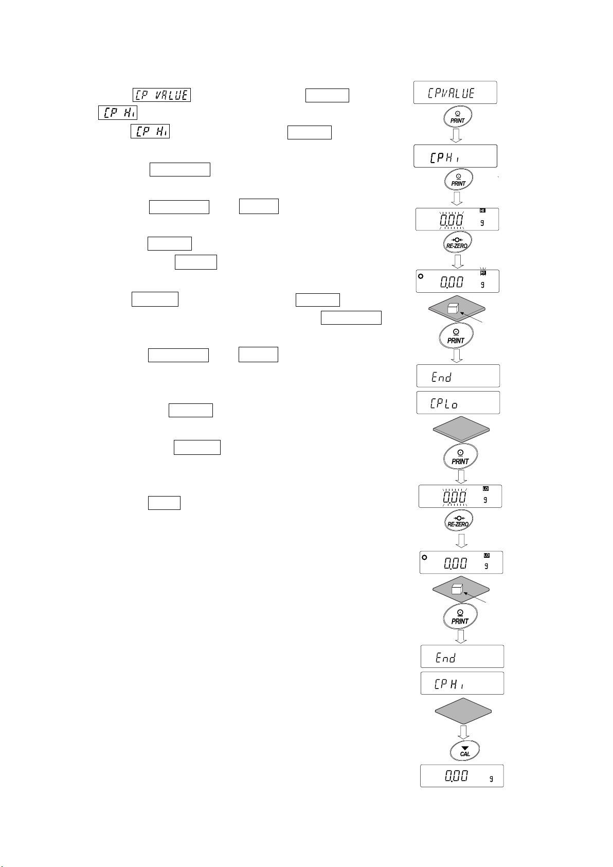
Entering the reference and tolerance values
Plac
e
a
s
am
p
le of
the
wei
ght
of
th
e up
per
li
mit
Rep
lace
a
sam
ple
x 2
Place a
sample
of
the we
ight of the lower
limit
10. When is displayed, press the PRINT key.
will be displayed.
When is displayed, press t he PRINT key to
11.
check the currently set v alue (all blinking).
Press the RE-ZERO key to enter the load input mode.
12. Press the RE-ZERO key,
0.00g is displayed. Place a
sample of the weight of the upper limit on the balance and
press the PRINT key. ( Re gist er the upper limit value.)
13. When finished, Cp lo is displayed. (Replace a sample of the
weight of the upper limit from the balance.)
14. When Cp lo is displayed, press the PRINT key to check
the currently set value (all blinking). Pre ss t he RE-ZERO key to
enter the load input mode.
15. Press the RE-ZERO key, 0.00g is displayed.
16. Place a sample of the weight of the lower limit on th e bal ance
and press the PRINT key. (Register the lower limit value.)
17. When finished,
Cp Hi is displayed. (Replace a sa mp le of the
weight of the lower limit from the balance.)
Press the CAL key twice to return to the weighing display.
65

Sound the built-in buzzer corresponding to the comparison result.
Press and Hold
d
out
P
re
s
s
s
ev
eral time
s
0
0
0
1
1
1
Comparison result
When the comparison r esult is HI
1 Press and hold the SAMPLE key (for 2 second s) until ba5fnc of
the function table is displayed.
2 Press the SAMPLE key several times to display Cp beep .
3 Press the PRINT key.
4 Press the SAMPLE key to set the buzzer sound setting
"ON/OFF" of the comparison result.
When 3-step comparator is set, the display can be selected
from the following 3 kinds .
When 5-step comparator is set, the display can be selected
from the following 5 kinds
.
.
SAMPLE key ··········· Select the comparison result.
RE-ZERO key········ Set the buzzer sound setting of the
···································comparison result "ON/OFF
PRINT key ···············S tore the setting.
CAL key ··············· Cancel and return to the weigh in g display.
(for 2 seconds)
11-9 Adding the Comparison Results
By setting the "Comparison results (Cp-R)" of the function table to "1", the comparison results can be
added to the data output using the RS-232C serial interface or USB interface. Use A&D standard format
(type 0).
The comparison results are added after the header in A&D standard format as below.
Header Data Unit Terminator
When the comparison r esult is OK
When the comparison r esult is LO
Not applicable
66

11-10 Main Display Comparison Function
The main display compa rison func tion displays the com parison results i n a magn ified way, on the m ain
portion of the display in place of the weight value.
Selecting a unit
Step 1 Press the MODE key to select a unit to be used for comparison.
Note While the main display comparison function is in use, unit selection using the MODE
key is n ot av ail abl e.
Setting the function table
Step 2 Press and hold the SAMPLE key (for 2 seconds) until ba5fnc of the function table is
displayed, then release the key.
Step 3 Press the SAMPLE key several times to display Cp fnc .
Step 4 Press the PRINT key.
Step 5 Press the SAMPLE key several times to display Cp-b 0 .
Step 6 Press the RE-ZERO key to display Cp-b 1 .
Note To disable the main display comparison function, set the "Main display comparison
(Cp-b)" parameter to "0".
Step 7 Press the PRINT key to store the sett ing.
Step 8 Press the CAL key to return to the weighing mode.
Setting the comparator values Setting the comparator values as described in the previous section. This example uses Cp 3 (Continuous comparison, excluding "near zero").
Using the main display com parison function
Step 1 Press the RE-ZERO key to set the d isp lay to z er o.
Step 2 Place a sample on the pan. The balance performs a comparison using the specified comparison
values and displays the comparison results, HI, OK or LO.
Step 3 Each time the MODE key is pressed, the balance switches between the standard display and
Notes
the main display comparison. Note that "go" appears for OK.
While the main display com parison function is in use, the processing indicator
illuminates as shown in the illus t r ation.
If the comparison is not perfor med, for example, bec ause the weight value is near
zero or unstable, the balance displays the weight value even when the main display
comparison fu nc t ion is used.
Even while the main display compariso n function is in use, the balance re-zeroing
and data output are possible.
Only the unit selected befor e thi s f unction can be used.
While the main display com parison function is in use, the data memory function i s
not available.
To disable the mai n display compar ison function, set the "Main dis play compariso n
(Cp-b)" parameter to "0".
67

data1
data2
data
Weighing data and
Main display
Example: a sample of 1 kg is pl aced.
Example: a sample of 2 kg is pl aced.
Example: a sample of 3 kg is pl aced.
Compares using the sp ecified compariso n values.
Each press alternates the display
(The processing indicator il lu m inates)
0 . 0
g
0 . 0
g
1 0 0 0 . 0
g
l o
g
2 0 0 0 . 0
g
g
3 0 0 0 . 0
g
Hi
g
Comparison results
(St andard display)
comparison
11-11 Description Of Application
Description of the normal weighing mode ( apf 0 ).
The normal weighing mod e of the factory setting.
Description of the weighing indicator mode ( apf 1 ).
The weighing indicator dis plays the relation between load and weighting capacity in percent in
normal weighing.
(Zero 0%, weighing capacity 100%)
Note:
It can not used with the settings "
□
or
" that use the data memory function (
).
Description of the statistical calculation mode ( apf 2 ).
This is a function to stat ist ically calculate the weighi ng value and to display and output the r es ult.
Refer to "14.Stat istical Calculation Mode " .
68

Description of the flow measurement mode ( apf 3 ).
Press and ho l d
Output
It is a function to calculate the flow measure m ent .
Refer to "15.Flow Measurement " .
Description of the gross net tare mode ( apf 4 ).
This is a function to operat e t he zero setting and taring se parately and to output t he data of Gross
(total amount), Net ( net amount) and Tare (tare quantity).
Refer to "16.Gross Net Tare Function".
11-12 Outputting the function setting information
Function setting can set the balance to appropriate oper at ions for your needs.
The function table menu consists of two layers. The first layer is the "Class" and the second layer is
the "Item".
By performing the following procedure, the function setting status can be output at once, so settings
of balance being used can be r ecor ded.
Outputting the function setting information at once
1. Press and hold the SAMPLE key (for 2 seconds) in
weighing mode
2. bA5Fnc is displayed.
3. Press and hold the PRINT key (for 2 seconds) to
display -L i5t- . A current function setting information is
output at once.
0.00
(for 2 seconds)
bA5Fnc
Press and ho l d
(for 2 seconds)
-L i5T-
End
bA5fnc
69

【Output example】
…
2019/01/22
123456789
LAB-0123
GX-10202M
ⓐ ⓑ
ⓒ
Model name
Serial number
ID
Date
Time
Output a data and time for the balance
ⓐ Class (2 characters)
ⓑ Item (8 characters)
ⓒ Parameter (1 character) or (12 characters)
* Each one is divided using comma.
* Refer to “11-2 Details Of The Function Table” in “11.
Table” for details of class, item and parameter.
Function
70

Use example 1 Outputting the function setting information to a printer
Use AD-8126 Mini printer or AD-8127 Multi printer .
1. Connect the printer to the balance.
When using AD-8127, set the print mode to “DUMP”.
Refer to instruction manual of the printer for detail s of the settings or print mode.
Refer to “Communication manual” on A&D web site (http://www.aandd.jp/) for details of the
connection method between t he balance and printer
2. Confirm that the communication can be made between the balance and printer and output an
information using “Output ting the function setting inf or m ation at once” described on pr evious page.
Use example 2 Outputting the function setting information to a PC
Refer to “Communication manual” and“WinCT manual”on A&D web site ( http://www.aandd.jp/) for
details of the USB setting or WinCT.
1. Connect between the PC and balance using the provided USB cable or sold separately RS-232C cable.
* Use the USB at virtual COM mode.
It cannot be output usi ng quick USB.
2. Install the WinCT t o a PC to be used.
Download WinCT software from A&D web site (http://www.aandd.jp/).
3. Start up RSCom and match communication settings such as COM port or baud rate to settings of
the balance.
Press the[Start]button to enable the communication.
4. Confirm that the communication can be made between the balance and PC and output an
information using “Output ting the function setting inf or m at ion at once” described on previous page.
71

12.ID Number And GLP Report
7 segm
ent 15 segm
ent
14 segment
11 se
gment
12-1 Main Objective
□ The ID number is used to identify the balance when Good Laboratory Practice (GLP) or G ood
Manufacturing Practice ( GMP) is used.
□ The data output compatible wi th "GLP/GMP" can be output to a personal computer or printer using the
RS-232 C serial int erface.
□ The GLP / GMP compliant report includes the balance manufacturer, model, serial number, ID
number, date, time and space for signature. It includes the results and using mass for calib ration
or calibration test data.
□ The balance can output the following report s for GLP/ GMP.
・"Calibration report" of the calibration, using the internal mass (Calibration due to changes in
temperature and one-touch calibration.)
・"Calibration report" of t he calibration, using an ext er nal weight.
・"Calibration test report" of the calibration test, using an ex t er nal weight.
・"Title blo ck" and "End block" for the weigh in g data.
□ Calibration and calibration test data can be stored in memory to output several reports at the
same time. Refer to "13. Dat a Memory" for details .
□ The ID number is use d to id entify the b alance w hen the balance is used for maintenance management.
□ The ID number is maintained in non-volat ile m emory even i f the AC a dapter is re moved.
□ For details on confirming and setting the time and date. Refer to "11-7. Clock and Calendar
Function".
□ It is also possible to output the clock data of an external device (such as a printer) without
outputting data of the clock built in to the balance.
12-2 Setting The ID Number
1. Press and hold the SAMPLE key (for 2 seconds) until ba5fnc of the function table is
displayed, then release the key.
2. Press the SAMPLE key several times to disp lay id .
3. Press the PRINT key. Set the ID number using the followi ng keys.
SAMPLE key ························· To select the digit to change the value.
RE-ZERO key, MODE key ······ To set the c haracter of the digit selected.
············································ Refer to the display charact er set shown below.
PRINT key ···························· To store the new ID number and display .
CAL key ································ To canc el the new ID number and display .
4. With displayed, press the CAL key to return to the weighing mode.
Note The display seg m ent of the balance is divided into
4types.
For each segment display, refer to the "Display
correspondence table" in the next page.
72
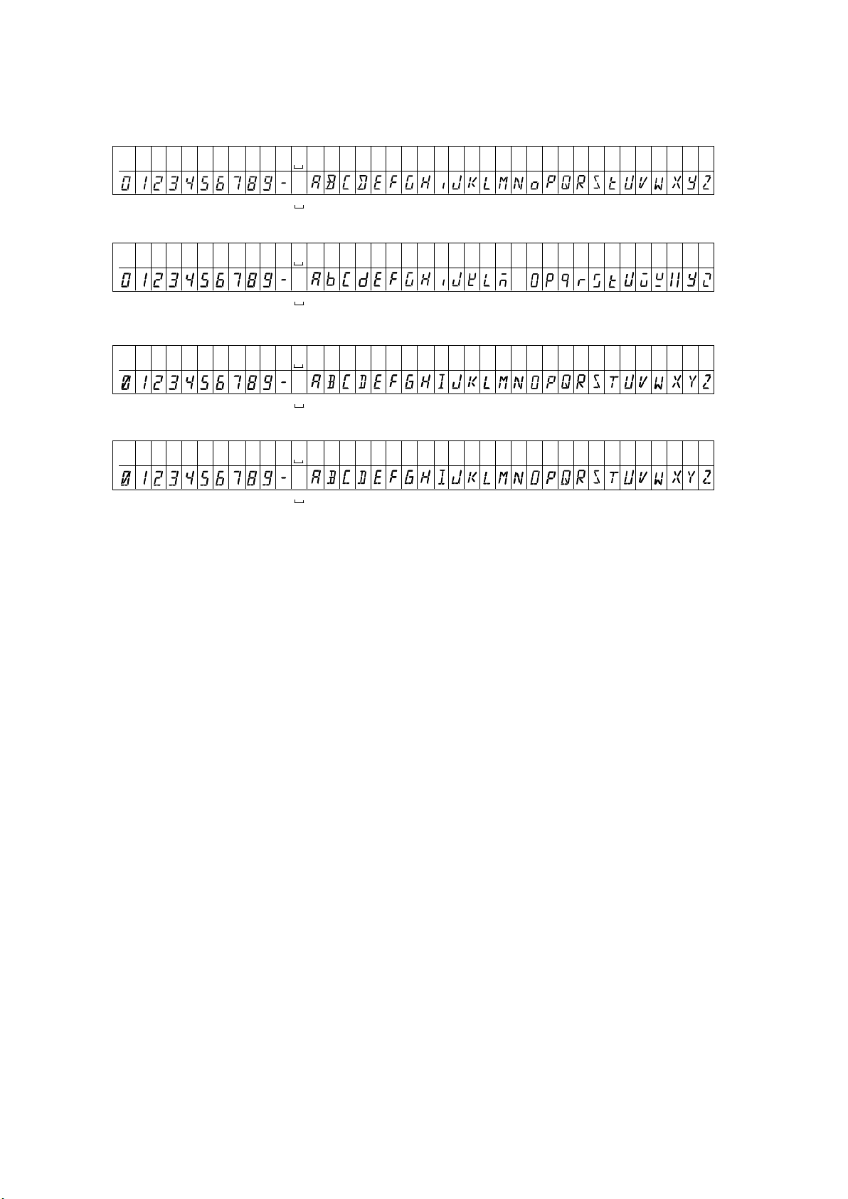
Display correspondence table
N
11 Segment
7 Segment
14 Segment
15 Segment
N O P Q R S T U V W X Y Z
Space
0 1 2 3 4 5 6 7 8 9
A B C D E F G H
-
J K L M
I
N O P Q R S T U V W X Y Z
Space
0 1 2 3 4 5 6 7 8 9
A B C D E F G H
-
J K L M
I
Space
0 1 2 3 4 5 6 7 8 9
A B C D E F G H
-
J K L M
I
N O P Q R S T U V W X Y Z
Space
0 1 2 3 4 5 6 7 8 9
A B C D E F G H
-
J K L M
I
N O P Q R S T U V W X Y Z
Space
0 1 2 3 4 5 6 7 8 9
A B C D E F G H
-
J K L M
N O P Q R S T U V W X Y Z
Space
0 1 2 3 4 5 6 7 8 9
A B C D E F G H
-
J K L M
I
N O P Q R S T U V W X Y Z
Space
0 1 2 3 4 5 6 7 8 9
A B C D E F G H
-
J K L M
73

12-3 GLP Report
CR
LF
Manufacturer
Model
Serial number
ID number
Date
Time
Calibration type
Remarks
Signature
PC format (RsCom)
A & D <T ERM >
MO DEL GX- 10 20 2 M< TE R M>
S/ N 123 45 67 8 9< TE R M>
ID LA B- 01 2 3< TE R M>
DA TE 2 017 /1 2/ 3 1< TE R M>
TI ME 12 :3 4: 5 6< TE R M>
CA LIB RA TED (I NT . )<T ER M >
RE MA R KS <T E R M >
<T ER M >
<T ER M >
SI GNA TU RE< TE RM >
<T ERM >
<T ERM >
-- -- -- -- -- -- -- --
<T ERM >
<T ERM >
<T ERM >
Space, ASCII 20h。
Terminator, CR LF or CR
Carriage return,ASCII 0Dh。
Line feed, ASCII 0Ah。
<TERM>
A & D
Output the clock data of built in balance (
info 1
)
Printer format (AD-8127)
Set the function setting to "info 1 " (use data of clock built in to the balance) or "info 2" (use clock data of
external equipment) to output the GLP / GMP data with a AD-8126 (mini printer), AD-8127 (multi printer) or
personal computer.
Note
□ In case of outputting clock data built in the balance (
info 1), if the time and date are not correct,
set the correct time and dat e in "Clock ( CLAdJ )" of the funct io n table.
Calibration report using the internal mass
This is the GLP report when the balance is calibrated using the internal mass.
74

Output the clock data of external device (info 2).
CR
LF
Printer format (AD-8127)
Manufacturer
Model
Serial number
ID number
Date
Time
Calibration type
Remarks
Signature
A & D <T E RM >
MO D EL G X- 1 02 02 M <T E RM >
S/ N 1 23 4 56 78 9 <T E RM >
ID LA B -0 12 3 <T E RM >
20 1 7/ 12 / 31 < TE RM >
12 : 34 :5 6 <T E RM >
CA L IB RA T ED ( IN T. )< TE R M>
RE MA R K S < T E R M>
<T ER M >
<T ER M >
SI G NA TU R E< T ER M>
<T E RM >
<T E RM >
-- -- -- - - - -- -- -- -
<T E RM >
<T E RM >
<T E RM >
Space, ASCII 20h。
Terminator, CR LF or CR
Carriage return,ASCII 0Dh。
Line feed, ASCII 0Ah。
<TERM>
By setting the function table "info 2" for outputting data such as GLP/GMP, the clock data of the external
device such as PC or printer can be used without using the clock data of the balance.
Note
□ Clock data output from external device is for devices that have a clock function and can receive
date and time data by receiving <ETC>D, <ETC>T.(Ex. AD-8127 multi printer, RsCom winCT
etc.)
□ When saving the calibration history of the data memory function, the built in clock data is saved
even if it is set to
"info 2"
75

Calibration report using an external weight
CR
LF
Setting
of
info 1
PC format (RsCom)
Manufacturer
Model
Serial number
ID number
Date
Time
Calibration type
<TERM>
Setting of
info 1
Printer format (AD-8127)
A & D
MODEL GX-10202
S/N 123456789
ID LAB-0123
DATE 2017/12/31
TIME 12:34:56
CALIBRATED(EXT.)
CAL.WEIGHT
+10000.00 g
REMARKS
SIGNATURE
Space, ASCII 20h
Terminator, CR LF or CR*
Carriage return,ASCII 0Dh*
Line feed, ASCII 0Ah*
Calibration weight
Remarks
Signature
<TERM>
<TERM>
<TERM>
<TERM>
<TERM>
<TERM>
<TERM>
<TERM>
<TERM>
<TERM>
A & D
MO D EL G X- 1 02 02M
S/ N 1 23 4 56 789
ID
LAB-0123
DA T E
2017/12/31
TI M E
12:34:56
CA L IB RA T ED ( EX T.)
CAL.WEIGHT
+ 10 0 00 . 00 g
RE M A R K S
<T E R M >
<T E R M >
SI G NA TU R E
<TERM>
<TERM>
-- - - - - - - - - - - - - - <TERM>
<TERM>
<TERM>
<TERM>
CR
LF
Space,
ASCII 20h
Terminator, CR*LF or CR
Carriage return, ASCII 0Dh
Line feed, ASCII 0Ah
<TERM>
A & D
MO D EL G X- 102 02 M
S/ N 1 23 456 78 9
ID
LAB-0123
DA T E
20 17 / 1 2 / 3 1
TI M E
12:34:56
CA L .T ES T (E XT. )
ACTUAL<TERM>
+0 .00 g
+9 9 99 .95 g
TARGET
+ 10 0 00 .00 g
RE MA R K S
<T ER M >
<T ER M >
SI G NA TU R E
<TERM>
<TERM>
Manufacture
Model
Serial number
ID number
Date
Time
Calibration test
Zero point value
Target weight
value
Target weight
Remarks
Signature
Setting of
info 1
Printer format (AD-8127)
Setting of
info 1
PC format (RsCom)
A & D
MODEL GX-10202
S/N 123456789
ID LAB-0123
DATE 2017/12/31
TIME 12:34:56
CAL.TEST(EXT.)
ACTUAL
0.00 g
+9999.95 g
TARGET
+10000.00 g
REMARKS
SIGNATURE
<TERM>
<TERM>
<TERM>
<TERM>
<TERM>
<TERM>
<TERM>
<TERM>
<TERM>
<TERM>
<TERM>
<TERM>
<TERM>
This is the GLP report when the balance is calibrated using the external w eight.
Calibration test report using an external weight
This is the GLP report when checking the weighing accuracy of the balance with the external weight.
(Adjustment is not perfor me d)
76

Heading and ending output
A & D<TERM>
MO D EL G X- 1 02 0 2M <TERM>
S/ N 1 23 4 56 7 89<TERM>
ID LAB-0123<TERM>
DA T E 2017/12/31<TERM>
ST A RT <TERM>
TI M E 12:34:56<TERM>
<TERM>
WT +12 34 . 56 g <TERM>
WT +12 34 . 61 g <TERM>
WT +12 34 . 62 g <TERM>
WT +12 34 . 63 g <TERM>
WT +12 34 . 51 g <TERM>
WT +12 34 . 53 g <TERM>
WT +12 34 . 71 g <TERM>
WT +12 34 . 64 g <TERM>
<TERM>
EN D <TERM>
TI M E 12:45:56<TERM>
RE MA R K S< T E R M >
<T ER M >
<T ER M >
SI G NA TUR
E<TERM>
<TERM>
<TERM>
Manufacrurer
Model
Serial number
ID number
Date
Time
CR
LF
Space, ASCII 20h
terminator, CR LF or CR
Carriage return, ASCII 0Dh
Line feed, ASCII 0Ah
<TERM>
Weighing data
Time
End block
Setting of
info 1
Printer format (AD-8127)
Setting of
info 1
PC format (RsCom)
A & D
MODEL GX-10202
S/N 123456789
ID LAB-0123
DATE 2017/12/31
START
TIME 12:34:56
WT +1234.56 g
WT +1234.61 g
WT +1234.62 g
WT +1234.61 g
WT +1234.61 g
WT +1234.53 g
WT +1234.71 g
WT +1234.64 g
END
TIME 12:45:56
REMARKS
SIGNATURE
Remarks
(Internal setting
type 1
)
(Interna settingl
Ttype 1
)
Titile block
Signature
Application / Operation
As a method of managing weighing values, add "Heading" and "End" parts before and after the
weighing value.
By pressing and holding the PRINT key (for 2 seconds), "Hea din g" and "End" are output in turn.
Note
If the data memory function is used (except when
Key output method
1. While displaying the weighing value, hold down the PRINT key (for 2 seconds) and display
5tart to output "Heading".
2. Output the weighing value. The output method depends on the setting of the data output mode.
3. Press and hold the PRINT key (for 2 second s) to display
data 0), heading and end cannot be output.
recend , "End" is output.
77

13.Data Memory
Upper limit value/lower limit value only
Data memory is a function to store weighing data and calibration data in memory. The data stored
in memory are available f or out putting at one time to a printer or personal computer.
The following five types of data can be stored.
Unit mass (Counting mode) Up to 50 set s
Weighing value Up to 200 set s
Calibration report
Internal calibration
External calibration
Calibration t est r eport
Internal test calibration
External test calibration
Last 50 sets
Comparator setting values
Tare value
Up to 20 set s
Up to 20 sets
13-1 Data Memory For Weighing Data
Features
□ It is not necessary to connect the printer or personal computer to the balance continually, because
the balance stores the weighi ng data in memory.
□ By storing the weighing value in the balance, weighing operation can be pe rformed without oc cupying
the printer or PC for a long time.
□ The data in memory can be displayed on the balance for confirmation.
□ Data (ID number, data number, time and date) to be added to the output data can be selected in
the function setting.
□ Up to 200 sets of weighin g data including time and dat e can be stored in memory of the balance.
* For the unit mass storag e method, refer to "6-2 Countin g M ode(PCS)".
Storing the weighing data and calibration history
Note
1. Set the "Data memory (data)" parameter to " data 2". Refer to "11. Function Table".
2. Set the "Time/Date output (5-td)" parameter about whether or not to add time and date.
3. The storing mode depends on the "Data output mode (prt)" parameter setting.
When set to prt3 (stream mode), data may not be stor ed corr ect ly.
*
It is also possible to change the time / date setting after storing the weighing value.
78

Enabling data memory function
Weighing display in
value
Number of stored data
Full memory
Press and hold
Press several times
CAL
2
0
OFF
(for 2 seconds)
1. Press and hold the SAMPLE key (for 2 seconds) until
1ba5fnc of the function table is displayed.
2. Press the SAMPLE key several times to display dout .
3. Press the PRINT key.
4. Press the SAMPLE key several times to display data .
5. Press the RE-ZERO key to d isplay .
6. Press the PRINT key to stor e the s ettin g.
7. Press the CAL key to return to the weighing mode.
bA5Fnc
dout
dAtA
dATA WT/
5 if
Display and symbol
Data number of the
displayed weighing
value
progress
Display of measured weighing
When the volume of measured
values stored reaches its
maximum, fUl dat
blink in turn.
Caution
□ When weighin g data is be ing stored i n memory, th e data is output simultaneo usly using RS-2 32C interface or
USB.
□ "fUl" indicates that memory is full or the memory capacity has been reached. More dat a cannot
be stored unless the memor y data is deleted.
□ Automatic self calibration can not be used while the int er val me mory mode is active.
□ Statistic calculation fun ction can not be used when the dat a memory function is active.
79

Setting the function table
Data output
Auto print
difference
Data
function
Auto print mode A
Auto print mode B
Key mode B(immediate)
Key mode C(stable)
Interval output mode
Yes
Time only
No
Date only
Yes
Both
Parameter settings for each output mode are as follows:
Item
Mode
Key mode
mode
prt 0
prt 1
prt 2
polarity,
Not used data 2
ap-a 0 ~ 2
ap-b 0 ~ 2
prt 4
prt 5 data 2
Not used
prt 6 data 2 int 0 ~ 8
Parameter settings for Data number, ID number, Time and Date
No d-no "0"
No
Data number
d-no "1"
5-id "0"
TTime
and date
ID number
5-id "1"
Recalling the memory data
Confirm that the "Dat a m emory (data)" par ameter is set to " data 2".
1. Press and hold the PRINT key (for 2 seconds) until
memory
data 2
data 2
data 2
Interval time
Not used
5-td 0 -
5-td 1
5-td 2
Up to 200
pieces
5-td 3
Left of the display
is displayed, then release the key.
The type of data appears in the upper left of the display as show n to
When setting without clock / date
the right "-d- or d-t" .
2. Press the PRINT key to enter the memory recall mode.
When setting with clock / date
Recall the data in memory using the following keys.
RE-ZERO key
MODE key
PRINT key
CAL key
......
...........
...........
...............
To proceed to the next data set.
To go back to the previous data set.
To transmit the current data using the RS-232C or USB.
To exit the memory recall mode.
3. Press the CAL key to return to the weighing mode.
* It is also possible to change the time / date output setting after storing the weighing value.
or
80

Transmitting all memory data at one time
No
Go
Output
No
Go
Delete
at once
Press
Press and hold
Press and hold
Confirm that the "Serial interface (5if)" parameters are set properly.
Refer to "10. Function Table" and "Communication Manual " on the A&D website.
1. Press and hold the PRINT key (for 2 seconds) until is
displayed, then release the key.
012
(for 2 seconds)
-d-
RECALL
2. Press the SAMPLE key to display out .
3. Press the PRINT key to display out with " " blinking.
4. Press the RE-ZERO key to display out with " " blinking.
5. Press the PRINT key to transmit all data using the RS-232C , USB.
6. The balance displays when all data is transmitted. Press the CAL key to return to the weighing mode.
Deleting all memory data at one time
1. Press and hold the PRINT key (for 2 seconds) until is
displayed, then release the key.
2. Press the SAMPLE key several times to display .
3. Press the PRINT key to display with " " blinking.
-d-
out
-d-
out
-d-
out
-d-
CLEAR
(for 2 seconds)
-d-
RECALL
4. Press the RE-ZERO key to display with blinking.
5. Press the PRINT key to delete all data
6. The balance displays end and returns to the wei ghi ng mode.
81
several times
-d-
CLEAR
-d-
CLEAR
-d-
CLEAR

13-2 Data Memory For Calibration And Calibration Test
Characteristic
□ Calibration data (when and how it is performed) and calibration test data can be
stored in memory.
□ All the data in memory is available to be output at one time to a printer or
personal computer.
□ Up to 50 data sets of the latest sensitivity adjustment or sensitivity
calibration can be stored.
* When the memory cap acity has been reached to 50, "fUl" " "
illuminates in order in the upper le f t of t he display as shown below.
Storing the calibration and calibration test data
1. Set the "Data memory (data)" p arameter to " data 2". Refer to "11. Fun ction Table".
2. With the settings above, each time calibration or calibration test is performed, the data is stored
automatically.
Upper left of the display
82

Transmitting the memory data
1. Press and hold the CAL key (for 2 seconds) during
weighing display. When a displayed, release
your finger from the key to display .
If there is no calibration history, is displayed,
and then the display retur ns to the weighing display.
2. Press the PRINT key to display .
3. Change the / with the RE-ZERO key.
Display the .
4. Press the PRINT key to start output at one time while
is displayed.
The output format confor ms to " G LP output".
When output at one time is completed, displays
5.
after is displayed.
6. If the saved history is deleted all at once, please proceed to
"How to delete history". To return to the weighing value, press
the CAL key.
* If the indicators blink in turn during
Press and hold
(for 2 seconds)
Release
When there is no c alibration history
Output at one time
weighing display, 50 instance of data are stored.
If history is saved in this state, old data will be overwritt en.
Optionally delete the s aved data.
83

Deleting data stored in memory
Press and hold
1. Press and hold the CAL key (for 2 seconds) until
is displayed, then release the key. is displayed.
2. Press the SAMPLE key to display .
3. Press the PRINT key to display .
4. Press the RE-ZERO key to change / .
Display .
5. Press PRINT while is displayed, deleting at
once is started.
6. When the balance displays and returns to the weighing
mode.
(for 2 seconds)
Release
Deleting
Delete at once
84

13-3
Unit mass data
No.3. Unit mass number
Data Memory for Unit Mass in the Counting Mode
The balance can store 50 data of unit mass for the counting mode.
"
p01
" is the standard memory of unit mass. Another 49 data of unit mass can be stored.
Even if the AC adapter is removed, the data is maintained in non-volatile memory.
The unit mass in memory can be recalled and used for weighing.
The unit mass in memory can be recalled and changed.
Note
The recalled uni t mass can be changed, using the weighing inpu t mode or the digital input m ode. The
weighing input mode uses the specified number of samples to store the unit mass. The digital input mode
enters the unit mass using the keys.
Storing the unit mass
To store a new unit mass: Recall the stored uni t mass to be change d. Then, change the recalled unit
mass using the weighing input mode or the digital input mode, and store the new unit mass.
The balance can stor e a unit mass from "Pp01" to "p50".
1. Set the "Data memory (data)" parameter to "1".
2. Press the MODE key to select pcs (counting mode).
Note If the counting mode can not be selected, refer
to "5. Weighing Units".
3. Press and hold the PRINT key (for 2 seconds) until
the balance enters the sample unit mass confirmation
mode. The unit mass last sel ect ed i s dis played
4. Select the unit mass number to be used, using the following keys.
RE-ZERO key To increase the unit mass number
by one.
MODE key
5. To change the selected unit mass:
To use the weighing input mode, press the SAMPLE key to enter the weighi ng input mode. Go to
"Weighing input mode" on the next page.
To use the di gital input mode, press the SAMPLE k ey, then press and hold the MODE key to
enter the digital input mode. Go to "Digital input mode" on the next page.
To decrease the unit mass by one.
85

Notes
Value
Decimal point
Store
ACAI can not be performed directly on the recalled unit mass.
Using the "UN:mm" command, the unit mass can be recalled.
The unit mass recalled can be output using the "?UW" command.
The unit mass can be changed using the "UW:" command.
"mm" indicates a two-digit numerical value 01 to 50, which corresponds to p01 - p50.
Weighing input mode
In the weighing input mode, the specified number of samples is placed on the pan to store the unit mass.
Re-storing the unit mass or performing Automatic Counting Accuracy Improvement (ACAI) on the
re-stored unit mass is possible. Follow the procedure described in "6-2. Counting Mode (PCS)".
Use the following keys to store a unit mass in the weighing input mode.
RE-ZERO key
SAMPLE key
PRINT key
CAL key
MODE key
...
.....
.........
.............
.........
To set the display to zero. 10 - pcs → 10 0 pcs
To change the number of samples to be stored. 10 0 pcs → 25 0 pcs
Press, after a sample is placed, to store the unit mass. Go to step 3 of the previous
page.
To return to the unit mass confirmation mode. Go to step 3 of the previous
page.
Press and hold (for 2 seconds) to go t o the digital input mode.
Digital input mode
To use this mode, the sam ple unit mass must be k nown before hand.
In the digital inpu t mode, the unit mass value is entered digitall y usi ng
the keys. The display in the digital input mode is shown to the right.
Note ACAI can not be used on the unit mass stored
using the digital input mode.
Use the following keys to store a unit mass in digital input mode.
SAMPLE key
RE-ZERO key
MODE key
PRINT key
CAL key
MODE key
Note If the new unit mass is out of the setting range, "error 2" is displayed.
Refer to "28. Specifications" for the minimum unit mass.
....
...
........
.........
.............
.........
To select the digit to be changed.
To change the value of the selected digit.
To change the decimal point position.
To store the unit mass. Go to step 3 of the prev ious page.
To return to the unit mass confirmation mode. Go to step 3 of the previous
page.
Press and hold (for 2 seconds) to go to the weighing input mode.
Digit
86
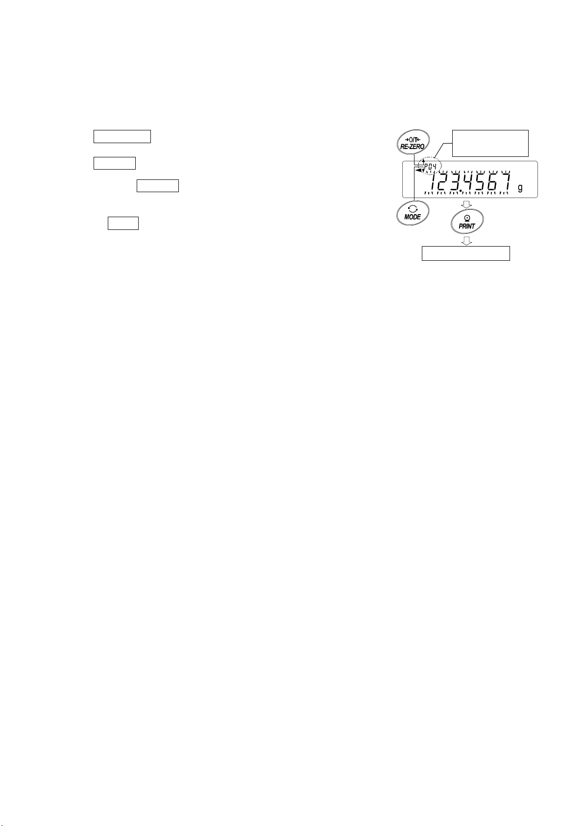
Recalling the unit mass
+1 -1
Confirm
Counting mode
mass
1. Follow steps1 through 3 in "St or ing the unit mass" on the prev ious page, to enter the sample unit
mass confirmation mode.
2. Select the unit mass number using the following keys.
RE-ZERO key To increase the unit mass num ber by
one.
MODE key
3. Press the PRINT key to confirm the selection and to ret ur n
to the weighing mode.
To cancel the selection and return to the weighin g m ode, pr ess
the CAL key
To decrease the unit mas s by one.
.
No4. of unit
87
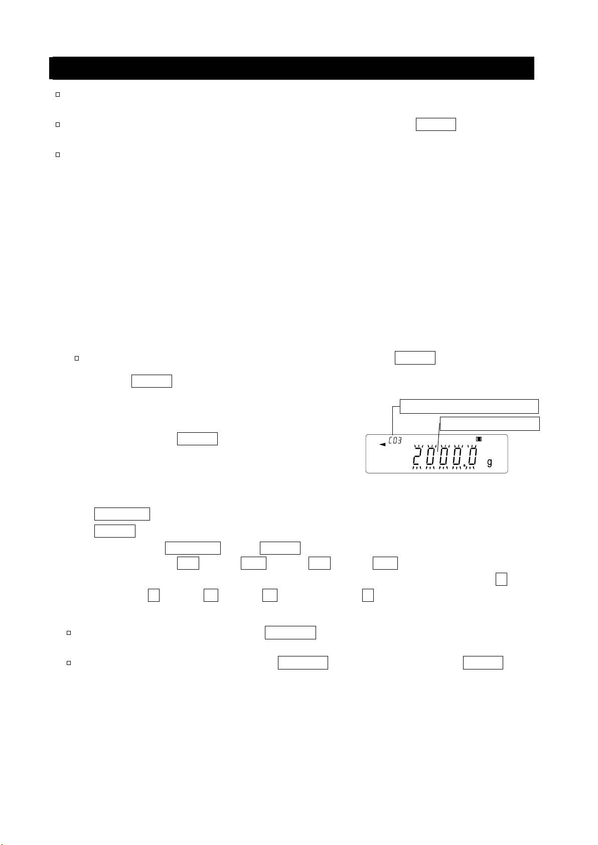
13-4 Data Memory for Comparator Settings
No.3. Comparator number
Upper limit value
The data memory function can store 20 sets of upper and lower limit values for the comparator mode.
The reference value or tolerance value for the comparator mode can not be stored in memory.
The upper and l ower limi t values in mem ory can be recalled easily using the MODE key and used f or
weighing.
The upper and lower limit values in memory can be recalled and changed.
Note
The recalled upper and lower limit values can be changed, using the d igital input mode or the
weighing input mode. The digital input mode enters the upper and lower limit values using the
keys. The weighing input mode uses a sample to store the upper and l ower limit values.
Storing the upper and lower limit values
To store new upper and lower l imit values: Recall the stored upper and lower limit val ues to be changed
("C01" to "C20") . Then, cha nge the recalled uppe r and l ower limi t values using t he digi tal inpu t mode o r
the weighing input mode, and store the new value.
Note
RE-ZERO key
MODE key
While the data memory function is in use, unit selection using the MODE key is not avai lable .
1. Press the MODE key to select a unit to be use d fo r
storage.
2. Set the "Data memory (data)" parameter to "3".
3. Press and hold the PRINT key (for 2 seconds) until
the balance enters the upper and lower limit values
confirmation mode. The upper limit value last selected
is displayed.
4. Select the compar at or number to be used, using the following keys.
..........
...............
Each time the RE-ZERO key or MODE key is pressed, the displayed value changes as
follows: ↔ C03 HI ↔ C03 LO ↔ C04 HI ↔ C04 LO ↔
In case of 5 level comparison, the displayed value changes in order of …⇔C03 HI blink
ing ⇔ C03 HI ⇔ C03 LO ⇔ C03 LO blinking ⇔ C04 HI blinking.
5. To change the selected upper and lower limit values:
To use the digital input mo de, press t he SAMPLE ke y to e nt er the di gital i nput mode. Go to "Digital
input mode" on the next page.
To use the weighing input mode, press the SAMPLE key, the n press and hold t he MODE key to
enter the weighing input mode. Go to "Weighing input mode" on the next page.
To increase the comparator number by one.
To decrease the comparator number by one.
88

Notes
Value
Digit
Polarity
Store
Comparator
number
Upper
limit
Store
Using the "CN:mm" command, the comparator limit values can be recalled.
The upper limit value recalled can be output using the "?HI" command.
The lower limit value recalled can be output using the "?LO" command.
The upper limit value can be changed us ing the "HI:" command.
The lower limit value can be changed using the "LO:" command.
"mm" indicates a two-digit numerical value 01 to 20, which corresponds to C01 - C20.
Digital input mode
In the digi tal inpu t mode, the upper an d lower limit val ues are entered
digitally using the keys. Use the followin g key s to stor e upp er a nd l ow er
limit values in digital input mode.
SAMPLE key
RE-ZERO key
MODE key
PRINT key
CAL key
Go to step 3 of the previous page.
MODE key
.....
...
.........
.........
.............
To select the digit to be changed.
To change the value of the selected digit.
To switch the polarity.
To store the upper and lower limit values.
Go to step 3 of the previ ous page.
To return to the upper and lower limit
values confirmation mode
C03 HI Upper limit value
Press and hold (for 2 seconds) to go to the weighing input mode.
Weighing input mode
In the weighing input mode, a sample is placed on the pan to store the upper and lower limit values.
Notes
Pressing the CAL key will interrupt the operation and the
balance will return to the upper and lower limit values confirmation
mode (step 3 in "Stori ng the upper and lo wer limit values").
To go to the digital input mode, press and ho ld the MODE key (for 2
seconds).
1. The first display in the weighing input mode depends on the comparator
number selected in step 4 in "Storing the upper and lower limit values".
For example, when "C03 H1 " is sele cted i n step 4, the display is the current
weight value and the comparator number with HI illuminating.
In case of second upper limit value, HI blinks
2. Place a container on the weighing pan, if necessary.
Press the RE-ZERO key to set the disp lay t o zero.
3. Place a sample correspondi ng t o t he upper limit value, on the pan or
in the container.
C03
Place a sample
corresponding to the
upper limit value
4. Press the PRINT key to store the upper limit value.
89

Recalling the upper and lower limit values (Quick selection mode)
Comparator
number
Upper
Store
Comparison with
no. 04
Lower
Target
Quick selection
The procedur e below describes an easy way to recall the upper and lower limit values to be used for
weighing. When the recalled uppe r and lowe r limit valu es are to be c hanged, refe r to "Storing the upper
and lower limit values".
Note
Refer to "Storing the upper and lower limit values" for the method to store the upper and lower
limit values.
1. Set the "Data memory (data)" parameter to "3".
2. Press the MODE key to enter the upper/l ow er limit value
recalling mode. The upper limit value last selected with its
comparator number app ears. The display is as show n to the
right, with all the digits blin king.
3. Press the MODE key to select the value. Each time the
MODE key is pressed, the displayed value changes as
follows:
........
(
4. Press the PRINT key to confirm the selection. The balance
Note To cancel the selection, press the CAL key. The
↔ C03 HI ↔ C03 LO ↔ C04 HI ↔ C04 LO
........
↔
returns to the weighing m ode with the selected upper and lower
limit values ready for use.
)
balance returns to the weighing mo de.
limit
limit
Number
90

13-5 Data Memory for Tare Value
t--
No.3 tare number
Tare value
The data memory function can store 20 sets of tare values for weighing.
The tare value in mem ory can be rec alled easily using the MODE key and used for weighing.
The tare value in memory can be recalled and changed.
Notes
The recalled tare value can be changed, using the digital input mode or the weighing input mode.
The digital input mode enters the tare value using the keys. The weighing input mode uses a
sample tare container to store the t are val ue.
The NET indicator illuminates during tare operation.
Storing the tare value
To store a new tare value : R ecall the sto red tare value to be changed ("t01" to "t20"). Then, change the
recalled tare value using the digital input mode or the weighing input mode, and store the new value.
Notes
The recalled tare value can be changed, using the digital input mode or the weighing input
mode. The digital input mode enters the tare value using the keys. The w eighing input mode
uses a sam ple tar e cont ainer to stor e the ta re val ue.
When the RE-ZERO key is pressed with nothing placed on the weighing pan, zero is
displayed, The NET indicator does not illuminate.
"
While the data memory function is in use, unit selection using the MODE key is not
" appears when a tare operation is performed without using the tare value stored in
memory.
available.
1. Press the MODE key to select a unit to be use d fo r storage.
2. Set the "Data memory (data)" parameter to "4".
3. Press and hold the PRINT key (for 2 seconds) until the
balance enters the tare value confirmation mode. The tare
value last selected is displayed.
4. Select the tare number to be used, using the following keys.
RE-ZERO key
MODE key
CAL key
.............
...................
......................
To increase the tare number by one.
To decrease the tare number by one.
To cancel it and to return to the weighing mode.
Each time the RE-ZERO key or MODE key is pressed, the displayed value cha nges as
follows: ↔ t03 ↔ t04 ↔
5. T change the selected tare value:
To use the weighing i nput mode, press the SAMPLE key to enter the weighi ng input mode. Go to
"Weighing input mode" on the next page.
To use the digital input mode, press the SAMPLE ke y, then press and hold the MODE key (for 2
seconds) to enter the di gital input mode. Go to "Digita l input mode" on the next pa ge.
........
↔t20 ↔ t01 ↔
91

Notes
Value
Digit
Store
風
袋
値
ナ
ン
バ
計
量皿に
風
袋を載
せる
登録
Tare number
Place container (tare)
Store
Using the "PN:mm" command, the tare value can be recalled.
The tare value recalled can be output using the "?PT" command.
The tare value can be changed using the "PT:" command.
"mm" indicates a two-digit numeral value 01 to 20, which corresponds to t01 - t20.
Weighing input mode
In the weighing input mode, a sample tare container is placed on the pan to st ore the tar e v alu e.
Note
Pressing the CAL k e y will interrupt the op eration and the balance will
return to the tare value confirmation mode (step 3 in "Storing the tare
value").
To go to the digital input mode, press and hold the MODE key.
1. The first display in the weighing input mode is the current weight value
and the selected tare number w it h PT blinking.
2. Press the RE-ZERO key to set the display to zero.
3. Place a tare (a container) on the weighing pan.
4. Press the PRINT key to store the tare value.
Remove the tare from the pan.
on the pan.
Digital input mode
In the digital input mode, the tare value is entered digitally using the
keys. Use the followi ng keys to stor e a tare valu e in digital inp ut mode.
SAMPLE key
RE-ZERO key
PRINT key
....
To select the digit to be changed.
...
To change the value of the selected digit.
.........
To store th e tare value.
Go to step 3 of " Storing the tare value".
CAL key
.............
To return to the tare value confirmation mode.
Go to step 3 of "Storing the tare value".
MODE key
.........
Press and hold to go to the weighing input mode.
92

Recalling the tare value (Quick selection mode)
Tare number
Tare value to
T ar e number
Tare v alue t o
Weighing is performed with
ready for
use.
Quick selection
T are value
The procedure below desc ribes an easy way to recall the tare value to be used for weighing. When the
recalled tare value is to be changed, refer to "St orin g the tar e v al ue".
1. Set the "Data memory (data)" parameter to "4".
2. Press the MODE key to enter the quick selection
mode. After entering quick selection mode, di splay
shows tare value (blinking ) , “ PT” mark and tare value
number. A prior selected setting value is displayed.
3. Press the MODE key to select the value. Each time
the MODE key is pressed, t he displayed value
changes as follows:
.....
(
4. Press the PRINT key to confirm the selection. The
Note To cancel the selection, press the CAL key. The
↔ t03 ↔ t04 ↔
balance returns to the weighing mode with the selected
tare value ready for use.
balance returns to the weighing mode.
........
↔t20 ↔ t01 ↔
...
)
the setting in t04
be used
Canceling the tare value data
Cancel the tare value data as follows:
1. Remove ev er ything from the weighing pan and press
the RE-ZERO key to cancel the tare value
.
be canceled.
93

13-6 Data Memory: Quick Selection Mode
data
data
No.3. Comparator number
Upper limit value
No.3, Tare number
Tare value
The data memory has a quick selection mode to recall data in memory quickly.
Using the quick selecti on mode, the comparato r settings or the tare value , whichever is selected in t he
function table, can be recalled, by a simple operation, using the MODE key.
Note
While the data memory function is in use, unit selection using the MODE key is n ot avai lable.
Use the quick selection mode as follows:
1. Press the MODE key to enter the quick selection mode.
The memory data last sel ect ed appears with all the digits blin kin g.
2. Press the MODE key to select the value.
Comparator settings: when the "Data memory (
Each time the MODE key is pressed, the displayed value changes as follows:
........
(
↔ C03 HI ↔ C03 LO ↔ C04 HI ↔ C04 LO ↔
)" parameter is set to "3"
........
)
T are value: when the "Data memory (
)" param et er i s set t o "4"
Each time the MODE key is pressed, the displayed value changes as follows:
........
(
3. Press the PRINT key or leave the balance as is for a while (after a few seconds of inactivity)
↔ t03 ↔ t04 ↔
to confirm the selection. T he balance returns to the weighing mode with the selected dat a r eady
for use.
Note To cancel the selection, press the CAL key. The bala nce returns to the weighing
mode
........
↔t20 ↔ t01 ↔
........
)
94

13-7 Data Memory: Confirmation and Storage Mode
data
data
data
data
No.3. Unit mass number
Unit mass value
No.3. Comparator number
Upper limit value
No.3, Tare number
Tare value
The confirmation and storage mode can change and store the recalled data.
Of the three types of memory data listed below, one may be selected in the function table, and is
available for changes using this mode.
Unit mass in the counting mode
Comparator settings
Tare value
Notes
To change the memory data other than specified in the function table, re-set the Data
memory (
For a detailed description of the procedure for each memory data, see the relevant sect i on.
Use the confirmation and storage mode as follows.
1. Press and hold the PRINT key (for 2 seconds) to enter the memory data rec al li ng mode. The
memory data last selected appears with all the digits bli nking.
2. Use the following keys to select the value.
RE-ZERO key
MODE key
)" parameter of the function table.
.............
..................
To increase the memory d ata number by one.
To decrease the memory dat a number by one.
Unit mass: when the "Data memory (
Each time the MODE key or RE-ZERO key is pressed, the displayed value changes as
follows:
The balance can select "p01" to "p50".
Comparator settings: when the "Data memory (
Each time the MODE key or RE-ZERO key is pressed, the displayed value changes as
follows:
T are value: when the "Data memory (
Each time the MODE key or RE-ZERO key is pressed, the displayed value changes as
follows:
........
↔ p03 ↔ p04 ↔
........
↔ C03 HI ↔ C03 LO ↔ C04 HI ↔ C04 LO ↔
........
↔ t03 ↔ t04 ↔
.......
........
)" parameter is set to "1"
)" parameter is set to "4"
↔t20 ↔ t01 ↔
95
)" parameter is set to "3"
........
........

3, Select a method.
To perform a weighing using the selected memory data
Press the PRINT k ey to confirm the selec tion. The balance will return to the weighing mode with the
selection ready for use.
To change and store the selected memory data
Press the SAMPLE key to enter the storage mode.
Two inputting modes are available for entering the value to be stored.
Digital input mode
Weighing input mode
To switch the inputting mode, press and hold the MODE key (for 2 seconds).
To cancel the operation and return to the weighing mode, press the CAL key.
96

(for 2 seconds)
14.Statistical Calculation Mode
where Xi is the i-th weight data,
N is number of data.
Press s
everal times
Press and hold
Press several times
Store the setting
Step7
Output statistic calculation
Step5
The statistical calculation mode statistically calculates the weight data, and displays or outputs the
results. To use the statistical calculation mode, set the "Application function (apf)" parameter of
“Application (ap fnc)" in the function table to "2", as described below. To return to the normal weighing
mode (factory setting), set "Application mode (apf)" to "0".
Statistical items available are number of data, sum, maximum, minimum, range (maximum-minimum),
average, standard deviation and coefficient of variation. What statistical items to output can be
selected from the four mo des i n the function table ( ) .
□ The wrong data input can be canceled by the ke y operation, if immediately af t er t he input.
□ Turning the balance off will delete the statistical data.
□ The standard dev iat i on and coefficient of variation are obtained by the equation below:
Standard deviation=
Coefficient of variation (CV)=
Relative error of maximum value =
Standard deviation
Average
Maximum value
Average
x 100 (%)
-
Average
x 100 (%)
Relative error of mini mu m value =
Minimum value
-
Average
x 100 (%)
Average
Note
□ When there is data with a minimum display digit off, the calculation result is displayed with the
minimum display digit off. (Minimum display digit is rounded off.)
□ When the data me m or y function is in use, the statist ical calculation function cannot be used.
□ When registering the warning function of the minimum weighing value, the statistical calculation
function cannot be used.
14-1 How To Use The Statistical Calculation
Switching to the Statistical Function Mode (Changing The Function Table)
1. Press and hold the SAMPLE key (for 2 seconds) until ba5fnc
2. Press the SAMPLE key several times to display 1ap fnc .
3. Press the PRINT key to display .
4. Press the RE-ZERO key several times
of the function table is d isplayed, then release the k ey.
to display .
To select statistical ite ms to output, go to step 5.
To store the statistical function mode setting, go to 7.
To disable the statistical calculation m ode, pr ess the
RRE-ZERO key to select
.
97

Selecting the statistical items to output
Parameter
Description
Number of data, sum
average
average, S tandard deviation, coefficient of variation
value
Unit
5. Press the SAMPLE key to display .
6. Press the RE-ZERO key to select the output items.
In the example, output the num ber of data, sum, maximum,
minimum, range (maximum-minimum) and average are
selected.
0
1
2
3
Number of data, sum
Maximum, minimum, range (maximum – minimum),
Number of data, sum
Maximum, minimum, range (maximum – minimum),
Number of data, sum
Maximum, minimum, range (maximum –
minimum),average, Stan dard deviation,coefficient of
variation
Relative error of maximum value, relative error of minimum
Continue from Step4
7. Press the PRINT key to store the setting.
8. Press the CAL key to return to the weighing mode.
Selecting the unit
9. Press the MODE key to select the unit to be used for the
statistical calculat io n m ode. In the example shown a t the right,
gram (g) is selected.
Note
Selecting the unit using the MODE key is not available after the data is entered. In this case,
clear the data as d escribed on pag e 99 "Cleaning the statis tical data" and select the unit usi ng
the MODE key.
When the unit used f or the statistic al calculation m ode is to be ena bled upon power -on, select
the unit in “Unit (
)” of the function table beforehand.
98

Entering data for statistical calculation
Use the following keys to operate the statistical calculation mode.
MODE key
..............
When the data is entered, moves between the displaying items (weighing mode,
statistical results and data operation) each time the key is pressed.
When no data has been entered, selects the unit.
SAMPLE key ......... Turns the minimum weighing value ON or OFF, in the weighing mode.
RE-ZERO key
........
Sets the display to zero in the weighing mode.
PRINT key .............. Outputs the data number and the weight data and includes the weight data to
statistical calculation in the weighing mode. (Out put is not in the dat a for mat
specified in the function table because of the data number added.)
Outputs the statistical results while the statistical results are d ispl ayed. (Output is
not in the data format specified in the function table.)
CAL key
..................
Returns to the weighing mode.
1. Press the RE-ZERO key to set the display to zero.
2. Place the sample on the weighing pan and wa it for t he
stabilization indicator t o t ur n on.
3. Press the PRINT key to add the data displayed to
statistical calculation. T he number of data on the upper
left of the display increases by 1.
4. Repeat steps 1 to 3 for each weighing.
Weighing pan
Sample
99

Outputting the statistical results
Symbol
Statistical item
Sum
Maximum
Minimum
Range (Maximum – minimum)
Average
Standard deviation
Coefficient of var iation
Relative error of maximum value
Relative error of minimum value
Output example
Function table
0
1
2
3
N 10
SUM
1
000.
00g
MAX
1
05.
00g
MI
N
9
5.00
g
R
10.
00g
AV
E
100
.00
g
SD
2
.800
g
C
V
2.
8
%
MA
X
%
5.
0
%
M
I
N%
5.
0
%
Output the statistical result
Delete
the latest data
Delete
the statistical data
Display
the statistical result
1. Each time the MODE key is pressed, the display
changes: the results as s elected in “Statistical functi on
mode output items (5taf)”, and ,
.
When pressing the SAMPLE key, the
previous item is displayed.
Note
□ When the number of data is 1, the coefficient of
variation and relat ive error is displayed as - - - - - - - .
□ When the average is 0, the coefficient of
variation and relative err or is display ed as - - - - - - - .
□ Statistical items are indic at ed on t he upper
left of t he display using the followin g
symbols.
2. When pressing the PRINT key while
displaying the statistical result, the statistical
result is output.
parameter
Deleting the latest data
When the wrong data is entered, it can be deleted and excluded from
statistical calculation. Only the latest data can be deleted.
1. In the weighing mode, press the MODE key several
times to display 1 .
2. Press the PRINT key to display .
3. Press the RE-ZERO key to display .
4. Press the PRINT key to delete the latest dat a and
exclude it from statistical calculation.
The number of data decreases by 1 when the balance
returns to the weighing m ode.
Press several times
100
 Loading...