

Page 1
GX-AE series
GX-124AE/GX-224AE/GX-324AE
GX-A series
GX-124A/GX-224A/GX-324A
GX-203A/GX-303A/GX-403A/GX-603A/GX-1003A/GX-1603A
GX-2002A/GX-3002A/GX-4002A/GX-6002A/GX-10002A
GX-6001A/GX-10001A
GF-A series
GF-124A/GF-224A/GF-324A
GF-123A/GF-203A/GF-303A/GF-403A/GF-603A/GF-1003A/GF-1603A
GF-1202A/GF-2002A/GF-3002A/GF-4002A
GF-6002A/GF-10002A/GF-6001A/GF-10001A
GX-AWP series
GX-203AWP/GX-403AWP/GX-603AWP
GX-2003AWP/GX-4002AWP/GX-6002AWP
GX-6001AWP
GF-AWP series
GF-203AWP/GF-403AWP/GF-603AWP
GF-2003AWP/GF-4002AWP/GF-6002AWP
GF-6001AWP
1WMPD4003475D
Page 2

© 2019 A&D Company Ltd. All rights reserved.
No part of this publication may be reproduced, transmitted, transcribed, or translated into
any language in any form by any means without the written permission of A&D Company
Ltd.
The contents of this manual and the specifications of the instrument covered by this
manual are subject to change for improvement without notice.
Windows, Word and Excel are registered trademarks of the Microsoft Corporation.
Page 3

Contents
1. Introduction .................................................................................................................... 7
1-1 Features ................................................................................................................................................ 7
1-2 About The Models .................................................................................................................................. 8
1-3 About The GX-AE Series ....................................................................................................................... 8
1-4 Compliance ............................................................................................................................................ 9
1-5 About Communication Manual .............................................................................................................. 9
2. Part Names, Installation And Precautions .................................................................... 10
2-1 Installing The Balance ......................................................................................................................... 14
2-2 Precautions .......................................................................................................................................... 14
2-3 During Use ........................................................................................................................................... 15
2-4 Precautions After Use .......................................................................................................................... 17
2-5 Power Supply ...................................................................................................................................... 17
3. Display Symbols And Key Operation ........................................................................... 18
4. Weighing ...................................................................................................................... 20
4-1 Units .................................................................................................................................................... 20
4-2 Basic Operation ................................................................................................................................... 25
4-3 Counting Mode (PCS) ......................................................................................................................... 27
4-4 Percent Mode (%) ............................................................................................................................... 29
4-5 Animal Weighing Mode (Hold Function) .............................................................................................. 30
5. Impact Shock Detection Function ................................................................................ 30
5-1 Recording Impact History .................................................................................................................... 31
5-2 Output Impact History .......................................................................................................................... 31
6. Response Adjustment / Self Check Function ............................................................... 32
6-1 Response Adjustment ......................................................................................................................... 33
6-2 Self Check Function / Automatic Setting Of Minimum Weighing Value By ECL ................................. 33
6-2-1 With Balance Software Version 1.200 To Version 1.220 .............................................................. 34
6-2-2 With Balance Software Version 1.300 or Later ............................................................................ 35
7. Sensitivity Adjustment .................................................................................................. 37
7-1 Automatic Sensitivity Adjustment (GX-AE/GX-A/GX-AWP Series Only) ............................................. 39
7-1-1 Inputting the set time .................................................................................................................... 40
7-1-2 Clearing the set time .................................................................................................................... 41
7-1-3 Setting the interval time ................................................................................................................ 42
7-2 Sensitivity Adjustment Using The Internal Mass (GX-AE/GX-A/GX-AWP Series Only) ........................ 44
7-3 Calibration Test Using The Internal Mass (GX-AE/GX-A Series 0.0001g Models Only) .................. 45
7-4 Sensitivity Adjustment Using An External Weight ............................................................................... 46
3
Page 4

7-5 Calibration Test Using An External Weight .......................................................................................... 47
7-6 How To Set The Sensitivity Adjustment Weight Value ......................................................................... 48
7-7 Correcting The Internal Mass Value Of The GX-AE/GX-A/GX-AWP Series ................................................................ 49
7-7-1 Correcting The Internal Mass Value Of The GX-AE/GX-A/GX-AWP Series (Auto) ..................... 50
7-7-2 Correcting The Internal Mass Value Of The GX-AE/GX-A/GX-AWP Series (Manual) ................. 51
8. Function Switch And Initialization ................................................................................. 53
8-1 Permit Or Inhibit .................................................................................................................................. 53
8-2 Initializing The Balance ....................................................................................................................... 56
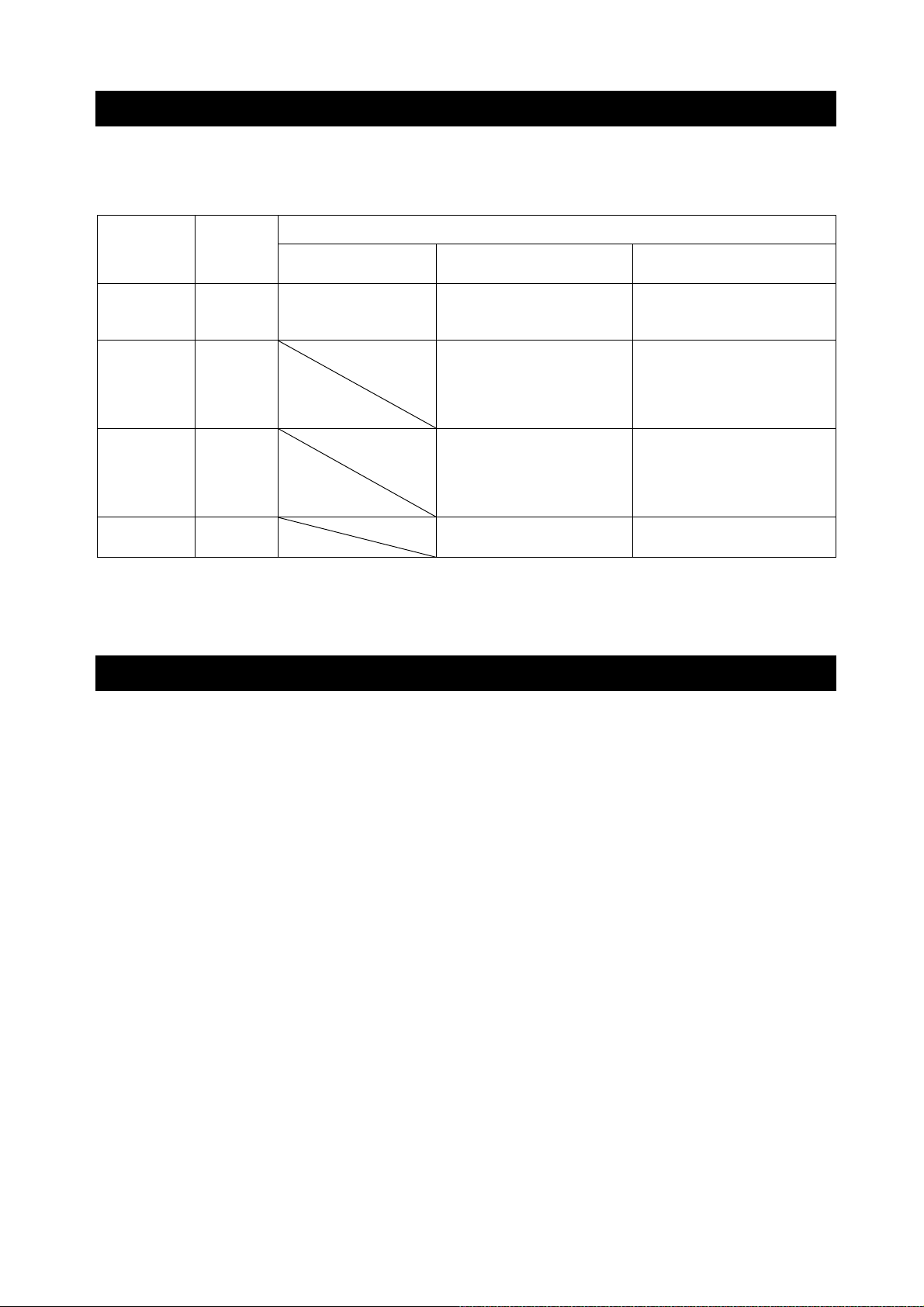
9. Function Table .............................................................................................................. 57
9-1 Setting The Function Table .................................................................................................................. 57
9-2 Details Of The Function Table ............................................................................................................. 59
9-3 Description Of The Class Environment Display .................................................................................. 66
9-4 Description Of The Data Output .......................................................................................................... 67
9-5 Description Of The Data Format ......................................................................................................... 67
9-6 Output Example Of The Data Format .................................................................................................. 67
9-7 Clock And Calendar Function .............................................................................................................. 68
9-8 Comparator Function ........................................................................................................................... 70
9-9 Description Of Application ................................................................................................................... 77
9-10 Output The Function Table Information ............................................................................................. 78
10. ID Number And GLP Report ....................................................................................... 80
10-1 Main Objective ................................................................................................................................... 80
10-2 Setting The ID Number ...................................................................................................................... 80
10-3 GLP Report ........................................................................................................................................ 81
11. Data Memory .............................................................................................................. 8 6
11-1 Data Memory For Weighing Data ...................................................................................................... 86
11-2 Data Memory For Sensitivity Adjustment And Calibration Test ......................................................... 90
12. Statistical Calculation Mode ....................................................................................... 93
12-1 How To Use The Statistical Calculation ............................................................................................. 93
12-2 Statistical Calculation Mode (Example Of Use) ................................................................................. 98
13. Flow Measurement .................................................................................................. 100
13-1 How To Use Flow Measurement ..................................................................................................... 100
14. Gross Net Tare Function .......................................................................................... 104
14-1 Preparations For Gross Net Tare Function...................................................................................... 104
14-2 Usage Example Of The Gross Net Tare Function ........................................................................... 106
15. Minimum Weighing Warning Function ...................................................................... 107
4
Page 5

15-1 Minimum Weighing Value Comparison ........................................................................................... 108
15-2 Input And Output Of The Minimum Weighing Value ........................................................................ 108
15-2-1 Procedure To Set In The Function Table (With Balance Software Version 1.200 To 1.220)
15-2-2 Procedure To Set In The Weighing Display (With Balance Software Version 1.200 To 1.220)
15-2-3 Procedure To Set In The Function Table (With Balance Software Version 1.300 Or Later)
15-2-4 P
15-2-5 Procedure To Output The Settings In Batch (Balance Software Version 1.300 Or Later)
15-3 Setting Measurement Tolerance Of Minimum Weighing Value ........................................................ 114
15-4 Data Output When Less Than Minimum Weighing Value ................................................................ 115
rocedure To Set In The Weighing Mode (Balance Software Version 1.300 Or Later)
................... 108
............... 109
.................... 109
......................... 112
.............................. 112
16. Underhook ............................................................................................................... 116
17. Programmable Unit .................................................................................................. 117
18. Density (Specific Gravity) Measurement .................................................................. 119
19. Password Lock Function .......................................................................................... 124
19-1 Balance Software Version 1.200 ..................................................................................................... 124
19-2 Balance Software Version 1.211 Or Later ....................................................................................... 125
19-3 Enabling Password Lock Function .................................................................................................. 126
19-4 Entering The Password At The Start Of Weighing .......................................................................... 127
19-5 Logging Out ..................................................................................................................................... 128
19-6 Registering (Changing) Password .................................................................................................. 129
19-7 Changing Password ........................................................................................................................ 130
19-8 Deleting Password (U5ER 01 to 10) .................................................................................................. 131
19-9 If Password Is Lost Or Forgotten .................................................................................................... 131
20. Repeatability Check Function
(GX-AE/GX-A/GX-AWP Series Only)
...................................................... 132
21. Interface Specification (Standard) ............................................................................ 133
22. Maintenance ............................................................................................................ 133
22-1 Treatment Of The Balance .............................................................................................................. 133
23. Troubleshooting ....................................................................................................... 134
23-1 Checking The Balance Performance And Environment .................................................................. 134
23-2 Error Codes ..................................................................................................................................... 135
23-3 Other Display ................................................................................................................................... 138
23-4 Asking For Repair ............................................................................................................................ 138
24. Connection With Peripheral Device ......................................................................... 138
24-1 Command ........................................................................................................................................ 138
24-2 Key Lock Function ........................................................................................................................... 138
25. How To Check The Software Version Of The Balance ................................................ 138
26. Specifications ........................................................................................................... 139
5
Page 6

26-1 Common Specifications ................................................................................................................... 139
26-1-1 Function .................................................................................................................................... 139
26-1-2 Size/Weight .............................................................................................................................. 139
26-2 Individual Specifications .................................................................................................................. 140
26-2-1 0.0001g Models ........................................................................................................................ 140
26-2-2 0.001g Models .......................................................................................................................... 141
26-2-3 0.01g Models ............................................................................................................................ 142
26-2-4 0.1g Model ................................................................................................................................ 143
27. External Dimensions ................................................................................................ 144
27-1 Options And Peripheral Instruments................................................................................................ 147
6
Page 7

1. Introduction
This manual describes how the GX-AE/GX-A/GF-A/GX-AWP/GF-AWP series balance works and how
to get the most out of it in terms of performance. Read this manual thoroughly before using the balance
and keep it at hand for future reference.
Behavior may differ depending on the software version of your balance.
For confirmation of the software version of the balance, refer to "25. How To Check The Software
Version Of The Balance".
1-1 Features
□ The balance has a self-check function that inspects the balance itself using electronically
controlled load (ECL) and evaluates performance.
□ The balance can detect impact applied to its mass sensor and display the level of that impact. ISD
(Impact Shock Detection).
□ Continuous change of the balance can be calculated as flow rate, displayed and output.
FRD (Flow Rate Display)
□ The balance is equipped with a data memory function, which can record weighing value, sensitivity
adjustment result, and multiple unit mass (mass per sample in counting mode) (Up to 200 items
are stored for weighing value).
□ The GX-AE/GX-A/GX-AWP series has automatic sensitivity adjustment using the internal mass,
adapting to temperature changes, setting time and interval time.
□ Good Laboratory Practice (GLP) / Good Manufacturing Practice (GMP) data can be output using
the RS-232C serial interface when performing sensitivity adjustment or calibration test. It is
possible to print and record the results using an optional printer.
□ A built-in clock and calendar that can add the time and date to the output data. (Setting and
changing of the time can be limited to only Administrator by using the password lock function.)
□ Comparator Indicators, displaying the comparison results with HI OK LO . (Depending on
the setting, 5-step comparison is also possible.)
□ Capacity Indicator, displaying the weight value in percentage relative to the weighing capacity.
□ Hold Function, provided for weighing a moving object such as an animal.
□ Underhook, for measuring density and weighing magnetic materials.
□ Using the key lock function, key operation of the balance is disabled and operations can be made
by commands from an external device only.
□ Users of the balance can be limited by setting a password. (Password lock function)
□ The balance is equipped with an RS-232C serial interface and a USB interface to communicate
with a computer. Windows computer using the Windows communication tools software (WinCT)
make building a system very easy. The latest WinCT software can be downloaded from the A&D
website.
Windows is a registered trademark or trademark of Microsoft Corporation in the United States and
other countries.
□ A small breeze break is included with the 0.001 g readability model.
□ A glass breeze break is included with the 0.0001 g readability model.
□ Dustproof and waterproof performance (IP65) of the product is that suitable for measuring
powders and liquids. When the optional waterproof RS-232C cable (AX-KO2737-500) is
connected, protection against dust and water can be provided even during communication.
(GX-AWP/GF-AWP only)
*If other than GXA-09 is used, protection against dust and water is not provided.
7
Page 8
1-2 About The Models
The GX-AE/GX-A/GF-A/GX-AWP/GF-AWP series consists of a variety of models with different
combinations of weighing capacity and readability. In this manual, they are classified by readability as
shown in the table below.
Model
Classification Readability
0.0001 g
model
0.001 g
model
0.01 g
model
0.1 g
model
0.0001 g
0.001 g
0.01 g
0.1 g
□ The GX-AE/GX-A/GX-AWP series has an internal mass for sensitivity adjustment.
□ The GF-A/GF-AWP series does not have an internal mass for sensitivity adjustment, so an
external weight is required separately for sensitivity adjustment.
Internal mass type,
with ionizer
GX-124AE
GX-224AE
GX-324AE
Internal mass type General type
GX-124A
GX-224A
GX-324A
GX-203A / GX-303A
GX-403A / GX-603A
GX-1003A / GX-1603A
GX-203AWP/GX-403AWP
GX-603AWP
GX-2002A / GX-3002A /
GX-4002A / GX-6002A /
GX-10002A
GX-2002AWP/GX-4002AWP
GX-6002AWP
GX-6001A / GX-10001A
GX-6001AWP
GF-123A/ GF-203A /
GF-303A /GF-403A /
GF-603A /GF-1003A /
GF-1603A / GF-203AWP
GF-403AWP / GF-603AWP
GF-1202A/ GF-2002A /
GF-3002A /GF-4002A /
GF-6002A /GF-10002A
GF-2002AWP/GF-4002AWP
GF-6002AWP
GF-6001A / GF-10001A
GF-6001AWP
GF-124A
GF-224A
GF-324A
1-3 About The GX-AE Series
□ An ionizer (static eliminator), which causes no breeze, is built into the breeze break. The ionizer
can eliminate static electricity from the weighing sample before weighing, reducing error due to
static electricity. (Static is eliminated by bipolar ions generated by direct-current corona discharge
being projected onto the sample.)
□ The ionizer electrodes are designed to be removed for cleaning and replacement.
□ An IR (touchless) switch is attached to the ionizer, and static elimination can be started without
touching ionizer.
□ Power is supplied from the balance to allow the ionizer to be operated without using an AC adapter.
□ PRINT or RE-ZERO or the static elimination function of the ionizer can be operated by using the
optional foot switch (AX-SW137-PRINT or AX-SW137-REZERO).
□ A removable glass breeze break is equipped as standard.
□ As an option board is installed, so other options (GXA-03/04/06/09/17/23/24/25/26, FXi-08, etc.)
cannot be used.
□ For instructions on using the ionizer and IR switch, download the instruction manual for "GXA-17
Large Glass Breeze Break with Ionizer" from our website (https://www.aandd.jp) and refer to it.
Static electricity
In general, when the ambient humidity is less than 45%RH, nonconductors such as powders, paper,
and plastics easily become charged with static electricity. The influence of static electricity may
cause a weighing error of several milligrams. The ionizer neutralizes this electrical charge.
8
Page 9

1-4 Compliance
Compliance with FCC Rules
Please note that this equipment generates, uses and can radiate radio frequency energy. This
equipment has been tested and has been found to comply with the limits of a Class A computing
device pursuant to Subpart J of Part 15 of FCC rules. These rules are designed to provide
reasonable protection against interference when equipment is operated in a commercial
environment. If this unit is operated in a residential area, it may cause some interference and under
these circumstances the user would be required to take, at his own expense, whatever measures
are necessary to eliminate the interference.
(FCC = Federal Communications Commission in the U.S.A.)
1-5 About Communication Manual
For details about communication, download "Communication manual" from our website
(https://www.aandd.jp) and refer to it.
9
Page 10
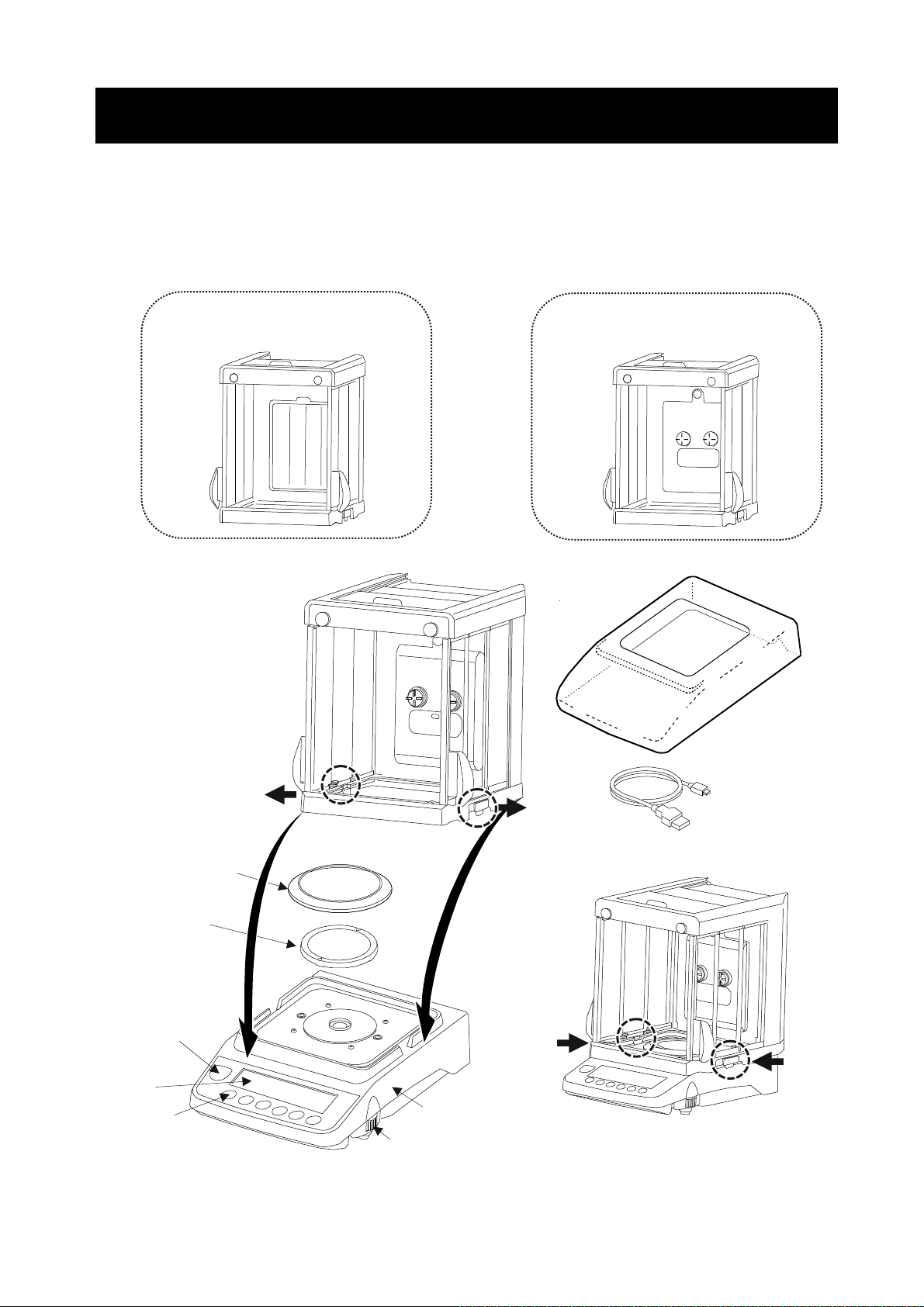
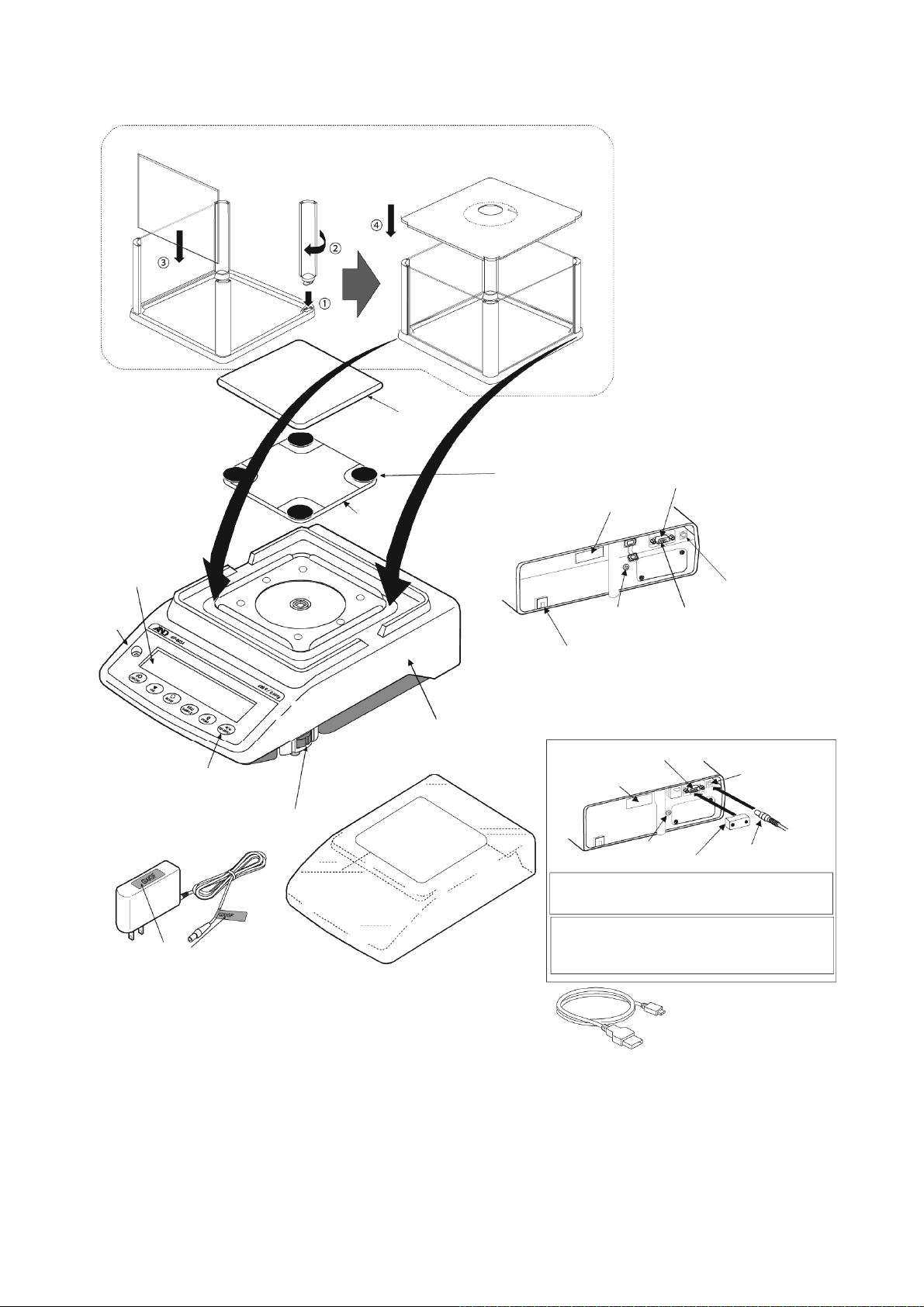
2. Part Names, Installation And Precautions
The balance is a precision instrument. Unpack it carefully. The packing contents depend on the
balance model. See the illustrations to confirm that everything is included. When options are combined
at time of shipping, optional accessories may be included.
Keep the packing material to be used for transporting the balance in the future.
GX-AE / GX-A / GF-A 0.0001g models
GX-A/GF-A GX-AE
Glass Breeze Break Glass Breeze Break with Ionizer
Main unit cover
(PET resin)
Pull out the left and right
locking handles.
USB cable (approx. 1.8m)
Breeze break ring
Weighing pan
Bubble spirit level
Display
Keys Main unit
Leveling foot Press the left and right locking handles
to secure the breeze break to the balance.
10
Page 11
Main unit rear side
A
A
r
A
r
A
The models with an ionizer built in to the glass breeze break (GX-124AE/GX-224AE/GX-324AE) have an
ionizer connector, IR sensor connector and external key jack.
Serial number
USB interface
RS-232C serial interface
C adapter jack
External key jack
Panel of GX-AE series
Ionizer connecto
Panel of GX-AE
series is different
Ground terminal
nti-theft hole
(Please prepare the security cable by yourself)
IR sensor connector
Connecting the glass breeze break with ionizer and the IR sensor
Models: GX-124AE / GX-224AE / GX-324AE
□ Insert the cable extending from the rear of the breeze
break into the ionizer connector at the rear of the
balance.
□ Insert the IR sensor plug into the IR sensor connector
at the rear of the balance.
External IR sensor
ttach the AC adapter label to the
adapter as shown below.
C adapte
AC adapter ID labels
Note
□ Please confirm that the AC adapter type is correct for your local voltage and receptacle type.
□ Please use the dedicated AC adapter specified for the balance.
□ Do not use the AC adapter provided with the balance for other models or equipment with which the
AC adapter may not be compatible.
□ If you use the wrong AC adapter, the balance and other equipment may not operate properly.
11
Page 12
GX-A / GF-A 0.001g models
A
A
r
r
A
k
r
A
r
A
r
A
A
r
f
A
r
j
r
ssemble the small breeze break (0.001g model only)
Follow the sequence as numbered.
Weighing pan
Pan
support
Pan support recepto
Main unit rear side
USB interface
Serial numbe
Display
Bubble
spirit
level
Keys
C adapte
Leveling foot
C adapte
ID label
ttach the AC adapter label to the
C adapter as shown above.
Note
Main unit
Main unit cove
C adapter jac
Ground
terminal
nti-theft hole
(Please prepare the security cable by yourself)
The GX-AWP/GF-AWP series comes with a
terminal cover.
RS-232C interface
Serial numbe
Insert the plug while rotating it. The plug is
designed to fit tight in order to prevent dust
from entering, so it is not easy to insert.
To protect the balance from dust/water,
attach the terminal cover or the waterproo
RS-232C cable (AX-KO2737-500).
RS-232C interface
Ground
terminal
USB cable
(Approx. 1.8 m)
C adapte
ack
AC adapter
Terminal cove
plug
□ Please confirm that the AC adapter type is correct for your local voltage and receptacle type.
□ Please use the dedicated AC adapter specified for the balance.
□ Do not use the AC adapter provided with the balance for other models or equipment with which the
AC adapter may not be compatible.
□ If you use the wrong AC adapter, the balance and other equipment may not operate properly.
12
Page 13
GX-A / GF-A 0.01g/0.1g models
r
r
A
A
r
A
r
j
r
r
I
hil
f
r
A
r
A
A
Weighing pan
Pan support recepto
Pan
support
Dust plate for
0.01g/0.1g
Display
Bubble
spirit
level
Keys
C adapte
C adapter
ID label
ttach the AC adapter label
to the AC adapter as shown
above.
Leveling foot
Main unit
(Please prepare the security cable by yourself)
Main unit cove
USB interface
Serial numbe
Main unit rear side
C adapter jack
Ground
terminal
nti-theft hole
The GX-AWP/GF-AWP series comes with a
terminal cover.
RS-232C interface
Serial numbe
Ground
terminal
nsert the plug w
designed to fit tight in order to prevent dust
from entering, so it is not easy to insert.
To protect the balance from dust/water,
attach the terminal cover or the waterproo
RS-232C cable (AX-KO2737-500).
RS-232C interface
Terminal cove
e rotating it. The plug is
C adapte
ack
AC adapte
plug
USB cable
(Approx. 1.8 m)
Note
□ Please confirm that the AC adapter type is correct for your local voltage and receptacle type.
□ Please use the dedicated AC adapter specified for the balance.
□ Do not use the AC adapter provided with the balance for other models or equipment with which the
AC adapter may not be compatible.
□ If you use the wrong AC adapter, the balance and other equipment may not operate properly.
13
Page 14

2-1 Installing The Balance
Step 1. Decide where to install the balance, taking into consideration the content of “2-2 Precautions”, below.
Step 2. Assemble the balance while referring to the explanations in the previous section.
Step 3. To level the balance, adjust the leveling feet so that the air bubble is in the red circle of the
bubble spirit level.
Step 4. Confirm that the adapter type is correct for the local voltage and power receptacle type.
Step 5. Insert the AC adapter into the AC adapter jack on the rear of the balance, and then plug the
AC adapter into an outlet.
2-2 Precautions
To get the optimum performance from the balance and acquire accurate weighing data, note the following:
□ Install the balance in an environment where the temperature and humidity are not excessive.
The best operating temperature is about 20°C ±2°C at about 45~60%RH relative humidity.
□ Install the balance where it is free of dust.
□ The weighing table should be solid, free from vibration and drafts, and as level as possible. (An
anti-vibration table or stone table is ideal)
□ Install the balance in a stable place avoiding vibration and shock. Corners of rooms on the first floor
are best, as they are less prone to vibration.
□ Install the balance where it is not affected by heaters or air conditioners.
□ Install the balance where it is not exposed to direct sunlight.
□ Install the balance away from equipment which produces
magnetic fields.
□ Level the balance by adjusting the leveling feet and confirm
it using the bubble spirit level.
□ Be sure to warm up the balance before use for at least 30
minutes (with the AC adapter connected to the power
supply).
□ Adjust the sensitivity of the balance before use or after
having moved it to another location. Refer to "7. Sensitivity
adjustment".
The GX-AWP/GF-AWP series
□ The dustproof and waterproof level of the balance is equivalent to IP65, and its second digit, “5”,
corresponds to "having no harmful influence by receiving direct jet of water". Washing with strong water
pressure or submersion in water may cause water to enter the balance and cause a malfunction.
□ When installing and using the balance under conditions requiring dustproof and waterproof
performance, make sure that the AC adapter plug is fully inserted into the AC adapter jack and that
the terminal cover is attached to the RS-232C interface or the waterproof RS-232C cable
(AXKO2737-500) is used.
□ If the RS-232C terminal cover is removed or the waterproof RS-232C cable (AX-KO2737-500) is not
used, protection against dust and water is not provided.
Caution
Leveling foot
Bubble spirit level
Do not install the balance where flammable or corrosive gas is present.
14
Page 15
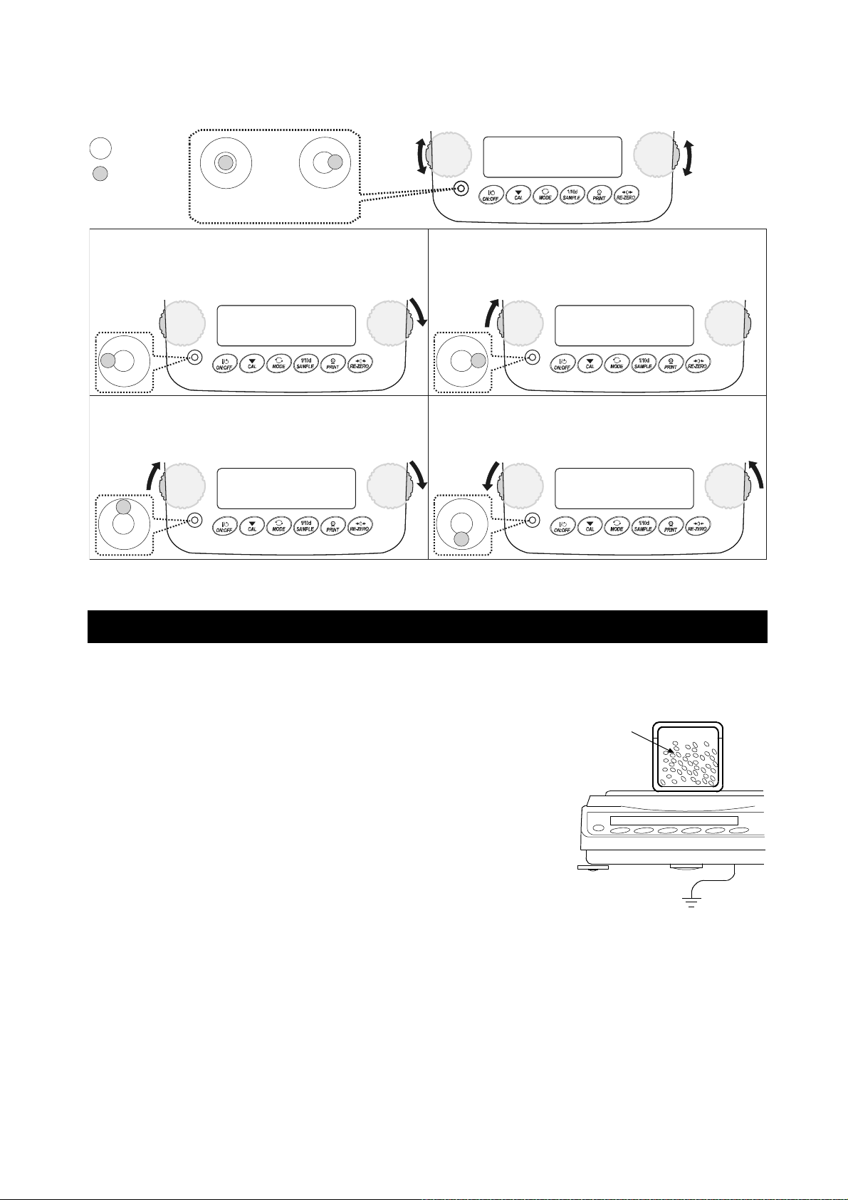
How to adjust the level of the balance
UP DOWN
Red circle
Bubble
OK Not OK
Leveling
foot
Leveling
foot
UPDOWN
When the bubble is off to the left:
Turn the leveling foot on the front right in the clockwise
direction.
When the bubble is off to the backward position:
Turn both leveling feet on the front in the clockwise
direction at the same time.
2-3 During Use
When the bubble is off to the right:
Turn the leveling foot on the front left in the clockwise
direction.
When the bubble is off to the forward position:
Turn both leveling feet on the front in the counter
clockwise direction at the same time.
For precise and accurate weighing, please take notice of the following.
□ Weighing errors may occur due to the influence of static
electricity. Note that if the ambient humidity drops below 45%RH,
insulators such as plastics are liable to have static electricity.
The Charged
sample
Ground the balance and perform the following as needed.
Use the built-in ionizer to remove static electricity (GX-AE
Metal case
series only).
Use the GXA-25 or AD-1683 static eliminator, sold separately,
to directly remove static electricity from the sample.
Increase the relative humidity at the place where the balance
is installed.
Weigh the sample in a conductive metal container or the like.
Ground
Wipe off charged materials such as plastic with a damp cloth
to suppress static electricity.
□ On models that come standard with a small breeze break, the parts of the small breeze break may
be charged for some time after being unpacked or when the humidity is low. If the measured value
is not stable or repeatability is poor, remove the small breeze break and try again. Wipe the
transparent plates with a damp cloth to remove static electricity to solve the problem of them
becoming charged. It is also effective to use the GXA-25 or AD-1683 static eliminator, sold
separately, or a commercially available antistatic agent.
15
Page 16
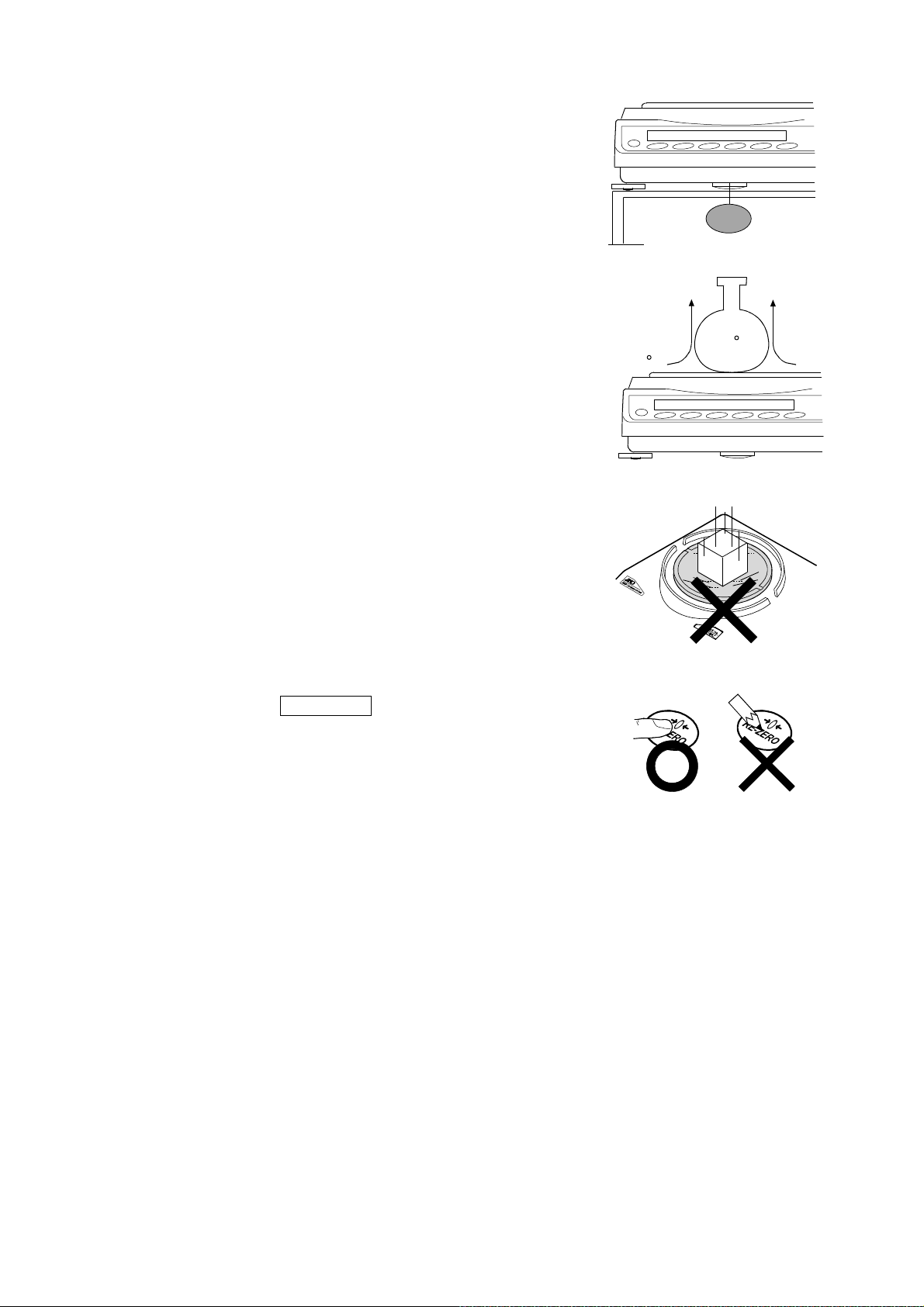
□ Influence of magnetism may cause weighing errors. When
measuring magnetic materials (iron, etc.), keep the sample away
from the balance main body by means such as underhook
weighing.
□ Weighing errors may occur if there is a difference between the
ambient temperature and temperature of the sample (and the
Magnetic
material
container). For example, when the room temperature is 20 °C,
convection occurs around a flask that is 40 °C and the balance
displays a value lighter than the actual weight. Before weighing
the sample and the container, try to acclimatize them to the
ambient temperature.
□ Perform the weighing operation carefully and quickly. If
Convection
40 C
20 C
measurement takes a long time, error-inducing factors will
increase due to changes in temperature and humidity in the
weighing chamber, air turbulence or reaction/humidity absorption
by the sample.
□ Do not leave the sample on the weighing pan for an extended
period of time. If a sample is left on the weighing pan for a long
time, the measured value will change due to deviation from the
zero point caused by environmental changes or due to creep
phenomenon.
□ When placing a sample on the weighing pan, do not drop it, or do
not place a sample greater than the balance weighing capacity.
Place the sample in the center of the weighing pan.
□ When pressing keys, do not press with a sharp object such as a
pen. Instead, press the center of the key with your finger.
□ Be sure to press the RE-ZERO key before weighing in order
to eliminate measurement errors.
□ Measurement results include error from air buoyancy. The
buoyancy of air varies depending on the sample volume,
atmospheric pressure, temperature and humidity. Correct the
buoyancy for the most precise measurement.
□ It is advisable to use the standard accessory display protection
cover in order to prevent foreign substances such as powder,
liquid and metal pieces from entering the balance.
GX-AWP/GF-AWP series
□ The balance is dustproof and waterproof, and the case is highly airtight. Therefore, for example,
minute pressure fluctuations in the chamber caused by opening and closing the door may cause
instability of the display. Before weighing, allow the pressure fluctuations to settle.
□ If water droplets or powder remains on the waterproof diaphragm and the pan support boss, the
performance of the balance may be impaired. Please clean the balance before using it.
□ If the waterproof diaphragm is deformed due to overload, etc., the weighing value may become
unstable until the deformation subsides.
16
Page 17

2-4 Precautions After Use
□ Avoid mechanical shock to the balance.
□ Do not disassemble the balance. Contact the local A&D dealer if the balance needs service or
repair.
□ Do not use organic solvents to clean the balance. Clean the balance with a lint free cloth that is
moistened with warm water and a mild detergent.
□ Avoid dust and water so that the balance weighs correctly. Protect the internal parts from liquid
spills and excessive dust.
□ The GX-AWP/GF-AWP series is dustproof and waterproof, but it cannot withstand water pressure
due to submersion and the like.
2-5 Power Supply
□ When the AC adapter is connected, the balance is in the standby mode if the standby indicator is
on. This is a normal state and does not harm the balance. For accurate weighing, keep the AC
adapter connected to the balance and AC power unless the balance is not to be used for a long
period of time. Please warm up the balance for at least 30 minutes (one hour for 0.0001g models).
17
Page 18
3. Display Symbols And Key Operation
r
A
r
r
Display symbols
Preset tare mark
Gross mark
Net mark
Processing indicato
Stabilization indicato
USB connecting mark
Standby indicator
Number of statistical data
(Statistical calculation mode)
Displays the weight data relative to the weighing
capacity, in percentage, in weighing mode
(Capacity indicator)
NET G PT
Displays weighing value, stored data, and item name
Blinking display contents
Response indicators
Comparator indicators
nimal weighing mark
Shock indicators
Unit display
Gross zero mark
Interval output mode
standby indicator
Data number being displayed
Processing indicato
Automatic sensitivity
adjustment notice
Interval output mode
active indicator
18
Page 19
Key operation
Key operations affect how the balance functions. Normal key operation during measurement is “Press
and release the key immediately” or “Press the key”. Please do not “Press and hold the key (for 2
seconds)” unless required.
Press the key Press and hold the key
Key
When pressed and released
Turns the display ON:OFF . The standby indicator is displayed when the display is
turned off. The weighing mode is enabled when the display is turned on.
When the password function is enabled, the password input display will be
displayed. Refer to "19-4 How to Input The Password At The Start Of Weighing"
This ON:OFF key is available anytime. Pressing the ON:OFF key during
operation will interrupt operation and turn the display OFF. *
In the weighing mode, turns the digit for
readability on and off.
In the counting or percent mode, enters the
sample storing mode.
(Press and release the key immediately.) for 2 seconds.
When pressed and held
(for 2 seconds)
Enters the function table mode.
Please refer to "9. Function Table".
Runs the repeatability check
function when pressed and held for
another 2 seconds after the
function table menu is displayed.
(GX-AE/GX-A/GX-AWP series
only)
Please refer to "20. Repeatability
Check Function".
Switches the weighing units stored in the
function table. Refer to “4. Weighing”.
Displaying of the unit mg is available for
0.0001g models only.
Performs sensitivity adjustment of the
balance using the internal mass.
(GX-AE/GX-A/GX-AWP series)
Stores the weighing data in memory or
outputs to a printer or personal computer
depending on the function table settings.
(Factory setting = output)
Sets the display to zero.
* When the "Gross net tare function" is selected, the display is turned off by pressing and holding
(for 2 seconds). Please refer to "14. Gross Net Tare Function".
Please refer to "6-2 Self Check
Function/ Automatic Setting Of
Minimum Weighing Value by ECL".
Displays other items of the sensitivity
adjustment menu.
Enters mode to change the unit mass
registration number in counting
mode.
By changing the function table:
Outputs "Title block" and "End
block" for GLP, GMP report.
Displays the data memory menu.
Enters mode for reading density
number in flow measurement.
19
Page 20
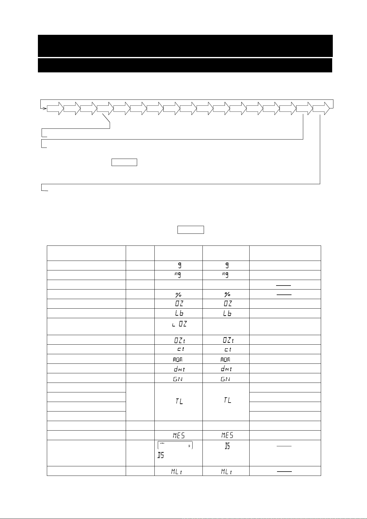
4. Weighing
4-1 Units
With the GX-AE/GX-A/GF-A series balance, the following weighing units and weighing modes are available:
Note: The unit "mg" is available for the 0.0001g models only. "mg" is displayed after "g" on 0.0001g models.
g
mg
PC
Pct OZ
Lb
L
OZ
OZt
Counting mode
Percent mode
Density mode (To use this mode, it must be stored in the function table as described on page
23. For details about this mode, refer to "18. Density (Specific Gravity) Measurement". To select
this mode, press the MODE key until the processing indicator blinks with the unit "g"
displayed. "DS" appears only when the density value is displayed.)
Programmable-unit (No unit displayed. For details, refer to "17. Programmable-Unit".)
A unit or mode can be selected and stored in the function table as described on page 23.
If a weighing mode (or unit of weight) has been turned off, that mode or unit will be missing in the
sequence. Tael has four varieties, one of which can be selected and installed at the factory.
To select a unit or mode for weighing, press the MODE key.
mom
ct
dwt
GN
TL
tol
MES
DS
MLT
For details about the units and modes, see the table below:
Name (unit, mode) Abbrev. Display
Function table
(Storing mode)
Conversion factor
1 g =
Gram g 1 g
Milligram mg 0.001 g
Counting mode PCS
pC5 pC5
Percent mode %
Ounce (Avoir) OZ 28.349523125 g
Pound Lb 453.59237 g
Pound/Ounce L OZ l0
Troy Ounce OZt 31.1034768 g
Metric Carat ct 0.2 g
Momme mom 3.75 g
Pennyweight dwt 1.55517384 g
Grain (UK) GN
Tae l (HK general, Singapore)
Tael (HK jewelry) 37.429 g
TL
37.7994 g
Tael (Taiwan) 37.5 g
Tael (China) 31.25 g
Tola (India) tol
to1
Messghal MES 4.6875 g
Density mode
(See note below)
DS
is used to
show the density.
Programmable-unit (Multi-unit) M LT
Note: The blinking processing indicator with “g” indicates that the density mode is selected.
1Lb=16 oz,
1 oz=28.349523125 g
0.06479891 g
11.6638038 g
to1
20
Page 21
The tables below indicate the weighing capacity and the readability for each unit, depending on the
(
)
balance model.
GX-124AE GX-224AE GX-324AE
Readability GX-124A GX-224A GX-324A
Unit
GF-124A GF-224A GF-324A
Gram
Milligram
Ounce (
Avoir
Troy Ounce
Metric Carat
Momme
Pennyweight
Grain (UK)
Tael (
HK general, Singapore
Tael (
HK jewelry
Tael (
Taiwan
Tael (
China
Tola (
India
Messghal
Unit
Capacity
122 220 320 0.0001
122000 220000 320000 0.1
)
)
)
)
)
)
GF-123A
GX-203A
GX-203AWP
GF-203A
GF-203AWP
4.30 7.05 10.50 0.00001
3.92 6.43 9.64 0.00001
610 1000 1500 0.001
32.5 53.3 80.0 0.0001
78.4 128 192 0.0001
1882 3086 4629 0.002
3.22 5.29 7.93 0.00001
3.25 5.34 8.01 0.00001
3.25 5.33 8.00 0.00001
3.90 6.40 9.60 0.00001
10.4 17.1 25.7 0.00001
26.0 42.6 64.0 0.0001
GX-303A
GF-303A
GX-403A
GX-403AWP
GF-403A
GF-403AWP
GX-603A
GX-603AWP
GF-603A
GF-603AWP
GX-1003A GX-1603A
GF-1003A GF-1603A
Readability
Gram
Ounce (
Avoir
Pound
Pound/Ounce
Troy Ounce
Metric Carat
Momme
Pennyweight
Grain (UK)
Tael (
HK general,
Singapore
)
Tael
HK jewelry
Tael (
Taiwan
Tael (
China
Tola (
India
Messghal
Capacity
122 220 320 420 620 1100 1620
)
)
)
)
4.30 7.76 11.28 14.81 21.86 38.80 57.14
0.268 0.485 0.705 0.925 1.366 2.425 3.571
0Lb 4.30oz 0Lb 7.76oz
3.92 7.07 10.28 13.50 19.93 35.36 52.08
610 1100 1600 2100 3100 5500 8100
32.5 58.6 85.3 112.0 165.3 293.3 432.0
78.4 141 205 270 398 707 1041
1882 3395 4938 6481 9568 16975 25000
3.22 5.82 8.46 11.11 16.40 29.10 42.85
3.25 5.87 8.54 11.22 16.56 29.38 43.28
3.25 5.86 8.53 11.20 16.53 29.33 43.20
3.90 7.04 10.24 13.44 19.84 35.20 51.84
10.4 18.8 27.4 36.0 53.1 94.3 138.8
26.0 46.9 68.2 89.6 132.2 234.6 345.6
0Lb
11.28oz
0Lb 14.81oz 1Lb 5.86oz 2Lb 6.80oz 3Lb 9.14oz
0.001
0.00005
0.000005
0.01oz
0.00005
0.005
0.0005
0.001
0.02
0.00005
0.00005
0.00005
0.00005
0.0001
0.0005
21
Page 22
(
)
)
)
Unit
GF-1202A
GX-2002A
GX-2002AWP
GF-2002A
GF-2002AWP
GX-3002A
GF-3002A
GX-4002A
GX-4002AWP
GF-4002A
GF-4002AWP
GX-6002A
GX-6002AWP
GF-6002A
GF-6002AWP
GX-10002A
GF-10002A
Capacity
Gram
1220 2200 3200 4200 6200 10200 0.01
Ounce (
Avoir
)
43.0 77.6 112.8 148.1 218.6 359.7 0.0005
Pound
2.68 4.85 7.05 9.25 13.66 22.48 0.00005
Pound/Ounce
Troy Ounce
Metric Carat
Momme
Pennyweight
Grain (
Tael
HK general,
Singapore
Tael (
HK
jewelry
Tael (
Taiwan
Tael (
China
Tola (
India
Messghal
2Lb 11.03oz 4Lb 13.60oz 7Lb 0.87oz 9Lb 4.15oz 13Lb 10.69oz 22Lb 7.79oz 0.01oz
39.2 70.7 102.8 135.0 199.3 327.9 0.0005
6100 11000 16000 21000 31000 51000 0.05
325 586 853 1120 1653 2720 0.005
784 1414 2057 2700 3986 6558 0.01
UK)
18827 33951 49383 64815 95680 157410 0.2
)
32.5 58.6 85.3 112.0 165.3 272.0 0.0005
)
39.0 70.4 102.4 134.4 198.4 326.4 0.0005
)
104 188 274 360 531 874 0.001
32.2 58.2 84.6 111.1 164.0 269.8 0.0005
32.5 58.7 85.4 112.2 165.6 272.5 0.0005
260 469 682 896 1322 2176 0.005
Unit
GX-6001A
GX-6001AWP
GF-6001A
GF-6001AWP
GX-10001A
GF-10001A
Readability
Readability
Gram
Ounce (
Avoir
Pound
Pound/Ounce
Troy Ounce
Metric Carat
Momme
Pennyweight
Grain (UK)
Tael (
HK general,
Singapore
Tael (
HK jewelry
Tael (
Taiwan
Tael (
China
Tola (
India
Messghal
Capacity
6200 10200 0.1
)
13Lb 10.69oz 22Lb 7.79oz 0.01oz
)
)
)
)
218 359 0.005
13.6 22.4 0.0005
199 327 0.005
31000 51000 0.5
1653 2720 0.05
3986 6558 0.1
95680 157410 2
164.0 269.0 0.005
165.0 272.0 0.005
165.0 272.0 0.005
198.0 326.0 0.005
531.0 874.0 0.01
1322 2176 0.05
22
Page 23
Storing Units
The units or modes can be selected and stored in the function table. The sequence of displaying the
units or modes can be arranged to fit the frequency of use.
The units are stored in non-volatile memory, even if the AC adapter is removed.
Select a unit or mode and arrange the sequence of display as follows:
1. Press and hold the SAMPLE key until of the
function table is displayed, then release the key.
2. Press the SAMPLE key several times to display
3. Press the PRINT key to enter the unit selection mode.
4. Specify a unit or mode in the order to be displayed using
the following keys.
SAMPLE key ꞏꞏꞏꞏꞏꞏ Displays the units sequentially.
RE-ZERO key ꞏꞏꞏꞏ Specifies a unit or mode. The
stabilization indicator
appears when the displayed unit or
mode is specified.
If the key is pressed in units already
selected, the stability mark disappears.
5. Press the PRINT key to store the units or modes. The
balance displays and then displays the next menu
of the function table.
.
6. Press the CAL key to exit the function table. Then the
balance returns to the weighing mode with the selected unit.
7. To select other unit or mode for weighing, press the MODE key.
23
Page 24
Unit setting example
The example below sets the units in the order with "g" (gram) as the first unit followed by pcs
(counting mode).
1. Press and hold the SAMPLE key until of
the function table is displayed, then release the key.
2. Press the SAMPLE key several times to display
.
3. Press the PRINT key to enter the unit selection
mode.
4. Press the RE-ZERO key to specify the unit of "g"
The stabilization indicator appears when the
unit is specified.
5. Press the SAMPLE key to display
6. Press the RE-ZERO key to specify the unit of pcs.
The stabilization indicator appears when the
unit is specified.
7. Press the PRINT key to store the units.
The balance displays and then displays the next
menu item of the function table.
8. Press the CAL key to exit the function table. Then
the balance returns to the weighing mode with g, the
unit selected first.
9. Press the MODE key to switch between g and pcs
(gpcs).
.
Press and hold
Press
several times
Specify
Select
Specify
Store
24
Page 25
4-2 Basic Operation
1. Press MODE key to select a unit.
Here, “ ” is selected as an example.
2. Place a container on the weighing pan if necessary.
Press the RE-ZERO key to cancel the weight (tare).
The balance displays 0.00
g
. (The decimal point position
depends on the balance model.)
3. Place a sample on the pan or in the container. Wait for the
stabilization indicator
to be displayed. Read the
value.
4. Remove the sample and container from the pan.
Note
□ Press the SAMPLE key to turn on or off the digit for the
Weighing
pan
Container
Sample
Remove the
sample
readability.
□ The weighing data can be stored in memory. For details, refer
to “11. Data Memory”.
□
When the ON:OFF key is pressed with a container placed
on the weighing pan and weighing is started, the balance
automatically cancels the weight (tare) and displays
0.00 g
.
25
Page 26
About the operation at when power is turned on
g
P
P
P
P
P
The balance will determine the reference zero point when the ON:OFF key is pressed to enter the
weighing mode.
Depending on the load condition at that time, it will automatically judge whether to perform zero or tare
operation. The condition for determining which is used is "power on zero range", and when power on
zero range is exceeded, the tare subtraction operation is performed.
About re-zero operation
By pressing the RE-ZERO key, the display can be changed to zero.
Re-zero with the RE-ZERO key will automatically determine whether zero or tare operation is
performed.
The condition for determining which is used is "zero range", and when zero range is exceeded, the tare
subtraction operation is performed.
About measurement range
For the balance, the range that can be weighed is determined by model.
The total amount (net amount + tare quantity) up to the maximum display of each model is displayed,
and when the maximum display is exceeded, E is displayed to indicate that the weighing range is
exceeded. When in excess in negative, -E is displayed.
Model
GX-124AE,
GX-124A,
GX-224AE,
GX-224A,
GX-324AE,
GX-324A,
GF-123A
GX-203A
GX-203AW
GX-303A GF-303A Approx.±6g
GX-403A
GX-403AW
GX-603A
GX-603AW
GX-1003A GF-1003A Approx.±20g
GX-1603A GF-1603A Approx.±32g
GF-1202A
GX-2002A
GX-2002AW
GX-3002A GF-3002A Approx.±60g
GX-4002A
GX-4002AWP,
GX-6002A
GX-6002AWP,
GX-10002A GF-10002A Approx.±200g
GX-6001A
GX-6001AW
GX-10001A GF-10001A Approx.±200g
GF-124A
GF-224A
GF-324A
GF-203A
,
GF-203AWP
GF-403A
,
GF-403AWP
GF-603A
,
GF-603AWP
GF-2002A
,
GF-2002AWP
GF-4002A
GF-4002AWP
GF-6002A
GF-6002AWP
GF-6001A
,
GF-6001AWP
Power on zero
ran
e
Approx.±50g
Approx.±100g
Approx.±1kg
Approx.±1kg
Zero range -E display range
Approx.±2g
Approx.±4g
Approx.±6g
Approx.±2g
Approx.±4g
Approx.±8g
Approx.±12g
Approx.±20g
Approx.±40g
Approx.±80g
Approx.±120g
Approx.±120g
Approx.-50g or less
Approx.-100g or less
Approx.-1kg or less
Approx.-1kg or less
26
Page 27
4-3 Counting Mode (PCS)
This is the mode to check the number of pieces. Based on the unit mass of the reference sample
(weight of one piece), the balance calculates and displays how many pieces are weighed. The smaller
the variation in the unit mass, the more accurate the count (the number of pieces). In addition, the ACAI
function described later can be used to further improve the counting accuracy while weighing.
Note
* It is recommended that the unit mass (weight of one piece) of the sample to be weighed should
be at least 10 times the readability (g) of the balance.
* If there is a large variation in the sample unit mass values, it may not be possible to count
accurately.
* If counting error is large, frequent use of the ACAI function is advisable. As one of the other
methods, try dividing the measurement into multiple times.
Selecting the counting mode
1. Press the MODE key to select PC5 ( PC5 = unit)
Storing a sample unit mass
2. Press the SAMPLE key to enter the sample unit mass storing
mode. Note that even in the storing mode, pressing the MODE.
key switches to the next mode.
3. To select the number of samples, press the SAMPLE key
several times. (1025501005 pieces)
Note
Since the sample unit mass is usually considered to have some
variation, the larger the number of samples for registration, the
more accurate the count can be.
4. Place a container on the weighing pan, if necessary.
Press the RE-ZERO key to cancel the weight (tare). The
number specified in step 3 appears.
25.0 is displayed if 25 is selected in step 3.
5. Place the specified number of samples on the pan. In this
example, 25 pieces.
6. Press the PRINT key to store the unit mass. The count display
appears. (e.g. 25 PC5 is displayed with 25 pieces.)
Note
* The balance prompts to add more samples if it judges that the
loaded sample is too light (resulting in large counting error).
Add the displayed number of samples and press the PRINT
key again. When the unit mass is stored correctly, the counting
display appears.
* If the balance judges that the mass of the sample is too light to
be registered as the unit mass, it displays Lo .
* Registered unit mass is stored even when the power is turned off.
Weighing pan
Container
Sample
(25 pieces)
place
(The counting result)
Counting mode
7. Counting operation is now possible.
27
Page 28
Automatic Counting Accuracy Improvement (ACAI)
This function automatically improves the counting accuracy as the
number of samples increases. (Errors will be reduced as sample
weight variations are averaged.)
After registering the unit mass in step 6, proceed to step 8 below.
8. Add a few samples. Then the processing indicator turns on. (Three or more samples are required
in order to prevent errors. The processing indicator does not turn on if overloaded. Add as many
samples as the displayed number.)
9. Do not touch or move the samples on the pan while the processing indicator is blinking. (The
accuracy is being updated.)
10. The accuracy is updated after the processing indicator turns out. Each time this process is
repeated, the counting accuracy will improve further. The range of ACAI after exceeding 100 is not
predetermined. Add as many samples as the displayed number.
11. Remove all the samples used with ACAI from the pan and start counting work.
Note
□ Do not change units during ACAI processing.
Processing mark
Storing the unit mass
With the data memory function, up to 50 unit masses can be stored.
1. Set the function setting item "Data memory (
unit mass in counting mode (
Refer to "9. Function Table".
2. The selected unit mass registration number is displayed in
)".
)" to "Stores
Press and
hold
" ** ".
3. Press and hold the PRINT key for 2 seconds to go to the
mode for changing the unit mass registration number.
RE-ZERO key (+) Changes the registration number.
MODE key (-) ꞏꞏꞏꞏꞏꞏ Changes the registration number.
PRINT key ꞏꞏꞏꞏꞏꞏꞏꞏꞏ Confirms the displayed registration number.
CAL key ꞏꞏꞏꞏꞏꞏꞏꞏꞏꞏꞏꞏꞏ Cancels the displayed registration number.
4. Register the unit mass, if necessary. Multiple unit masses can be stored by registering them with
different unit mass registration numbers.
**: The unit weight registration number is displayed.
□
Note
□ Unit weight can be read by ″ UN:mm ″ command.
(mm corresponds to P01 to P50 with 01 to 50.)
For details about the communication, download "Communication manual" from our website
(https://www.aandd.jp) and refer to it.
□ The read unit mass can output by ″ ?UW″ command and can be changed by ″UW: ″
command.
Caution
□ ACAI is not applicable to the read unit mass.
28
Page 29
4-4 Percent Mode (%)
The percent mode displays the weighting value in percentage compared with a reference mass as
100%. This is useful for target weighing or sample variance check.
Selecting Percent Mode
1. Press the MODE key to select the unit % (percent mode).
Storing a Reference Mass as 100%
2. Press the SAMPLE key to enter the mode for storing a 100%
reference mass.
Note that pressing the MODE key switches from this mode to
the next mode.
3. Place a container on the weighing pan, if necessary.
Weighing pan
Press the
RE-ZERO key to display 100.00 % .
4. Place a sample of 100% reference mass on the pan/container.
5. Press the PRINT key to store the 100% reference mass.
The balance displays 100.00
%
.
Note
□ Lo appears if the balance judges that the sample is too light to
be registered as a 100% reference mass.
□ The decimal point position varies according to the 100% reference
mass.
Model 100% mass Decimal point position
0.0001g readability
0.001g readability
0.01g readability
0.0100g to 0.0999g
0.1000g to 0.9999g
1.0000g or more
0.100g to 0.999g
1.000g to 9.999g
10.000g or more
1.00g to 9.99g
10.00g to 99.99g
100.00g or more
1%
0.1%
0.01%
1%
0.1%
0.01%
1%
0.1%
0.01%
Container
Sample
(100%)
place
Display % of weighing object
0.1g readability
1.0g to 9.9g
10.0g to 99.9g
100.0g or more
1%
0.1%
0.01%
□ The stored reference mass is stored in non-volatile memory even if the AC adapter is removed.
Percentage weighing
6. Percentage weighing is now possible.
29
Page 30
4-5 Animal Weighing Mode (Hold Function)
This is the mode to weigh a moving object such as an animal, even when the display of the weighing
data fluctuates. The hold function allows the average weight of the animal to be displayed. To use
the hold function, set the function in the function table. Refer to "9. Function Table" and "9-3
Description Of The Class Environment Display" for details.
5. Impact Shock Detection Function
The GX-AE/GX-A/GF-A series has a function to detect impact shocks to the mass sensor section
and to display the impact level.
By lowering the impact level at the time of loading, it is possible not only to alleviate variation in the
weighing value but also to reduce the risk of failure of the mass sensor section.
Especially when incorporating the balance in a production line, etc. and weighing by means such as
an automated system, impact to the sensor may be applied greater than expected. When designing
automatic systems and the like, it is recommended that you minimize the impact level as much as
possible while checking the shock indicator.
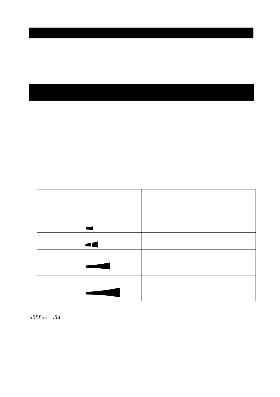
The shock indicator has 5 levels from level 0 to level 4.
Impact level Shock indicator Buzzer Contents
0 No indicator
SHOCK
1
SHOCK
2
SHOCK
3
SHOCK
4
With balance software version 1.300 or later, you can turn off the impact shock detection by setting
No
beeps
No
beeps
No
beeps
One
beep
Two
beeps
Safe
Caution
Caution:
Alleviate impact shocks
Warning:
Do not apply any more impact shocks
Danger:
Sensor may be damaged
/ to 0 in the function table. Even if the impact shock detection function is turned off, a
record is kept in the balance when there is a shock impact.
Note
□ Impact on the weighing sensor is not only that applied to the weighing pan when loaded, but also
may be impact applied from the table on which the balance is installed. The impact detection
function also works for impact coming from the table.
30
Page 31
5-1 Recording Impact History
Impacts of impact level 3 or higher are stored on the balance with data and time (up to 50 instances).
When the password lock function is ON (
when outputting the impact history. (Balance software version 1.211 or later.)
Note
□ If data instances exceeds 50, the stored data with the lowest impact level will be overwritten.
□ The stored impact history cannot be deleted.
□ Impact data where the balance is not energized (during transport, etc.) is not stored.
or
2
), the login user information is added
5-2 Output Impact History
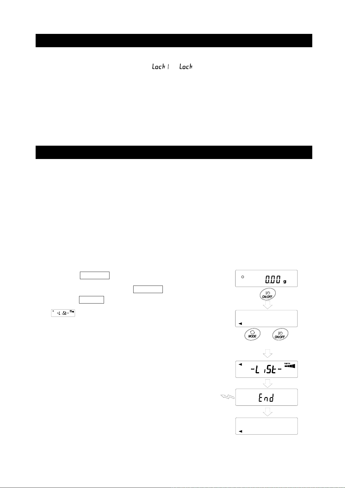
The stored impact history can be output by sending a specified command to the balance or performing
key operation.
Note
□ The impact history format differs depending on the software version of the balance.
Output by command
The stored impact data will be output all at once by sending a “ ?SA” command to the balance.
Output by key operation (Balance software version 1.200 or later.)
1. Press the ON:OFF key to turn off the display.
2. With the display off, press the ON:OFF key while holding
down the MODE key.
3. is displayed, and the stored impact data is output
all at once.
Press and Hold
Output
Press
31
Page 32

Impact history output example
The impact history format differs depending on the balance software version.
□ With balance software version 1.200
Date, time, and impact level are each output on a separate line.
Output example,
2018/05/29
11:08:18
SHOCK LV4
□ With balance software version 1.211 or later
Date, time, impact level, login and login user information are output together on one line.
The login user information varies depending on the setting of the login user and the setting of
Lock
in the function table when receiving impact.
Output Login user
, --,
,00, ADMIN Administrator
,01~10,USER User
, --,GUEST
Output example
2018/05/29,11:08:18,SHOCK LV,3, --,
2018/05/29,11:12:27,SHOCK LV,4,00,ADMIN
2018/05/29,11:13:38,SHOCK LV,3,01,USER
2018/05/29,11:17:04,SHOCK LV,4, -- ,GUEST
No login user
Guest
Function table
, ,
Lock
6. Response Adjustment / Self Check Function
Disturbances such as drafts and vibration at the place where the balance is installed affect weighing. In
the response adjustment settings, the response characteristics of the balance can be set in three
stages according to the disturbance. With the self check function, the balance itself inspects balance
operation and checks balance performance.
Indicator
FAST
MID.
SLOW
Function
setting
Faster response, Lower display stability
Slower response, Higher display stability
Response characteristic
32
Response indicator
Page 33

6-1 Response Adjustment
Response adjustment can be changed by the following method.
1. Press and hold the
RESPONSE is displayed, and then press the MODE
key again.
2. Press the
FAST , MID or SLOW can be selected.
3. After a few seconds of inactivity the balance displays
End .
Then, the balance returns to the weighing mode and
displays the updated response indicator.
The response indicator remains displayed for a while
(for 30 seconds).
Note
When setting the Response adjustment, "Condition (Cond)"
and "Display refresh rate (
"Environment display (
MODE key to select a weighing speed.
MODE key for 2 seconds until
)" in the Function Table
)" are changed as below.
Press and Hold
Release and
press again
Each pressing switches
the indicators
After a while
Display (Condition) (Display refresh rate)
FAST
MID.
SLOW
When using a combination other than the above, set individually as shown in "9. Function Table".
Note
If RESPONSE is displayed and you leave it without pressing the MODE key, the "Self-check
function" is activated. Refer to "6-2 Self Check Function". For the setting method, refer to "9.
Function Table".
(Stability band width)
6-2 Self Check Function / Automatic Setting Of Minimum
Weighing Value By ECL
With the self check function, repeatability can be confirmed and displayed in addition to performing
failure diagnosis, and whether or not the balance's performance is being exhibited can be easily
checked. It is also possible to display and register the minimum weighing value (reference value)
using repeatability data. For details of the minimum weighing value, refer to the technical information
on our website. (https://www.aandd.jp)
33
Page 34

6-2-1 With Balance Software Version 1.200 To Version 1.220
1. Press and hold the MODE key for 2 seconds in weighing mode.
2. Release the key when the RESPONSE display blinks.
3.
be displayed in a few seconds. If the MODE key is pressed with
displayed, changes in weighing values in the
repeatability measurement with the electronically controlled load
(ECL) can be seen.
(Available with balance software
version 1.100 or later)
4. When the diagnosis is completed, the
diagnosis result is displayed.
If there are no problems inside the
balance,
blinking.
If
a possibility that a fatal fault has
occurred inside the balance. Please
contact your local A&D dealer for repair.
SAMPLE
key…Switches the display between
diagnostic result, repeatability, and minimum
appears, and the self check function starts. "ECL" will
displays
displays blinking, there is
weighing value (reference value).
PRINT key…Outputs the displayed content.
When repeatability is displayed,
specifications are met. If catalog specifications are
exceeded,
review of the installation environment is issued.
(Available with balance software version 1.100 or later)
5. Press the CAL key to display End and return to
weighing mode.
6. To register as minimum weighing value of the minimum
weight value display warning function, press the RE-ZERO
key, which toggles between “No” and “Go”. When is
displayed, press the PRINT key.
If you do not want to register, press the PRINT key with
displayed or press the CAL key to return to weighing
mode.
* For minimum weighing warning function, refer to "15. Minimum Weighing Warning Function".
displays blinking and a request for
lights if catalog
Note
With the balance software version 1.200, the self check function can only be executed when the
login is made by Administrator (AdMin) if the password lock function is ON.
34
Page 35

6-2-2 With Balance Software Version 1.300 or Later
Setting procedure (See also the setting procedure flowchart on the next page)
1. Press and hold the MODE key for 2 seconds in weighing mode.
2. Release the key when the RESPONSE display blinks.
3.
If the MODE key is pressed with
repeatability measurement with the electronically controlled load (ECL) can be seen.
4. When the diagnosis is completed, the diagnosis result is displayed.
If there are no problems inside the balance, the
displays blinking, there is a possibility that a fatal fault has occurred inside the balance. Please
contact your local A&D dealer for repair.
When repeatability is displayed,
specifications are exceeded,
environment is issued.
SAMPLE key ꞏꞏ Switches the display between diagnostic result, repeatability, and minimum
PRINT key ꞏꞏꞏꞏꞏ Outputs the displayed content.
MODE key ꞏꞏꞏꞏꞏ Switches the measurement tolerance of the minimum weighing value
appears, and the self check function starts. "ECL" will be displayed in a few seconds.
lights if catalog specifications are met. If catalog
displays blinking and a request for review of the installation
weighing value (reference value).
(reference value).
displayed, changes in weighing values in the
displays blinking. If
With the minimum weighing value (reference value) displayed, the following operations can be
performed with the keys.
5. Batch output of the minimum weighing value data
Press and hold the PRINT key for 2 seconds to display out . When batch output is
completed, End will be displayed.
6. Registration of the minimum weighing value (reference value) described in "15. Minimum
Weighing Warning Function"
Press and hold the SAMPLE key for 2 seconds to display MW 5Et
minimum weighing value (reference value). When registration is completed,
displayed, and then the balance returns to weighing mode.
7. No registration
Press the CAL key to display End . The balance returns to weighing mode.
8. Diagnostic result display
Press the SAMPLE key to return to the diagnostic result display (step 4).
* For minimum weighing warning function, refer to " 15. Minimum Weighting Warning Function".
and to register the
End
will be
35
Page 36

Setting procedure flowchart
Step 1
Press and hold
for 2 seconds
Change in weighing value of repeatability
4.82
[ Diagnosis result ]
Request for repair
Output
Output
0 . 1
Output
fail
No problem in
performance
%
ref
Step 2
Release
Step 3
A few seconds later
1
[ Diagnosis result ]
No problem Step 4
12.3
Improvement of
installation environment
is required
0 . 1
1
%
0.96
0.96
ref
%
54.60
ref
1
%
ref
5.46
Example of
batch output
Batch
output
Step 5
Press and hold
for 2 seconds
out
Step 6
Press and hold for
2 seconds
go
Resister the minimum weighing value
When MW-CP is set to 0,
automatically set to 1 and
comparator function is available.
5et
Step 7
Step 8
36
Page 37

7. Sensitivity Adjustment
Since the balance's resolution is high, weighing values may change due to gravity and daily
environmental changes. It is necessary to perform sensitivity adjustment with the weight in order to
keep the weighing values from changing even if gravity or the environment changes.
It is recommended that you perform sensitivity adjustment if the balance is installed for the first time or
relocated, or when the weighing values change significantly in daily inspection, etc.
Sensitivity adjustment means to adjust the weighing value of the balance using the reference weight or
internal mass. Calibration test is to weigh with the reference weight and compare how much the result
deviates from the reference value. (Sensitivity adjustment is not performed in calibration test.)
Sensitivity adjustment
Automatic sensitivity adjustment ꞏꞏꞏꞏꞏꞏꞏꞏꞏꞏꞏꞏꞏꞏꞏꞏꞏꞏꞏꞏꞏ Automatically adjust the balance using the internal
mass according to ambient temperature change, set
time or interval time. (GX-AE/GX-A/GX-AWP series)
Sensitivity adjustment using the internal mass ꞏꞏꞏ Using the internal mass, adjust the balance with a
single touch. (GX-AE/GX-A/GX-AWP series)
Sensitivity adjustment using an external weight ꞏꞏ Using an external mass, adjust the balance with an
external mass.
Calibration test
Calibration test with an external weight ꞏꞏꞏꞏꞏꞏꞏꞏꞏꞏꞏꞏꞏ Output the result of checking the accuracy of
weighing using your own weight.
* No adjustment is made.
Calibration test with an internal mass ꞏꞏꞏꞏꞏꞏꞏꞏꞏꞏꞏꞏꞏꞏ Output the result of checking the accuracy of
weighing using the internal mass.
* No adjustment is made.
(GX-AE/GX-A series 0.0001g models)
Caution
□ Do not allow vibration or drafts to affect the balance during sensitivity adjustment.
□ To output the data for GLP/GMP using the RS-232C interface, set "GLP/GMP output (
"Data output (
GLP/GMP report. If the time/date is not correct, you need to adjust it. Refer to "9-7 Clock and
Calendar Function". The calibration test is a function that is active only when the output of
maintenance records compatible with GLP/GMP, etc. is set.
□ By setting "Data memory (
calibration test report can be stored in memory.
)". Refer to "9. Function Table". The time and date can be added to the
)" of the function table, the data of sensitivity adjustment report and
)" of
37
Page 38

Caution when using your external weight
□ The accuracy of the weight used in sensitivity adjustment affects the accuracy of the balance after
sensitivity adjustment.
□ Select the mass to be used for sensitivity adjustment and calibration tests from the table below.
Model Usable calibration weight
GX-124AE,
GX-124A,
GX-224AE,
GX-224A, GF-224A
GX-324AE,
GX-324A, GF-324A
GF-123A 50g, 100g 100g
GX-203A,
GX-203AWP
GX-303A, GF-303A 50g, 100g ~ 300g (100g interval) 200g
GX-403A,
GX-403AWP,
GX-603A,
GX-603AWP,
GF-124A
GF-203A
GF-203AWP
GF-403A
GF-403AWP
GF-603A
GF-603AWP
50g, 100g 100g
50g, 100g, 200g
50g, 100g, 200g, 300g
50g, 100g, 200g 200g
50g, 100g ~ 400g (100g interval) 400g
50g, 100g ~ 600g (100g interval) 500g
Factory
setting
200g
Adjustable
range
-0.9999g ~
+0.9999g
-9.999g ~
+9.999g
GX-1003A, GF-1003A 50g, 100g ~ 1000g (100g interval) 1000g
GX-1603A, GF-1603A 50g, 100g ~ 1600g (100g interval) 1000g
GF-1202A 500g, 1000g 1000g
GX-2002A,
GX-2002AWP,
GX-3002A, GF-3002A 500g, 1000g ~ 3000g (1000g interval)
GX-4002A,
GX-4002AWP,
GX-6002A,
GX-6002AWP,
GX-10002A, GF-10002A 500g, 1000g ~ 10000g (1000g
GX-6001A,
GX-6001AWP,
GX-10001A, GF-10001A 500g, 1000g ~ 10000g (1000g
GF-2002A
GF-2002AWP
GF-4002A
GF-4002AWP
GF-6002A
GF-6002AWP
GF-6001A
GF-6001AWP
500g, 1000g, 2000g
2000g
500g, 1000g ~ 4000g (1000g interval) 4000g
500g, 1000g ~ 6000g (1000g interval) 5000g
10000g
interval)
500g, 1000g ~ 6000g (1000g interval) 5000g
10000g
interval)
-99.99g ~
+99.99g
-99.9g ~
+99.9g
Display
This indicator means sensitivity adjustment data (sensitivity adjustment
and calibration test) is being imported. Do not allow vibration or drafts to
affect the balance while the indicator is displayed.
38
Page 39

7-1 Automatic Sensitivity Adjustment (GX-AE/GX-A/GX-AWP
Series Only)
This function automatically adjusts the sensitivity of the balance according to ambient temperature
change, set time or interval time. It works even when the display is off. If GLP output is selected in the
function table, the balance outputs the sensitivity adjustment report after the sensitivity adjustment.
□ In the automatic sensitivity adjustment mode, the temperature change (CFnc 0), the set time
(CFnc 1), or the interval time (CFnc 2) can be set with the function setting CFnc.
□ For the set time, three items, CtiME 1, CtiME 2 and CtME 3, can be set in the function table.
□ Interval time can be set from 0.5h to 24h with function setting C
i nt.
Caution
If something is on the weighing pan, the balance itself will judge that it is in use and will not perform
automatic sensitivity adjustment.
The criteria for performing automatic sensitivity adjustment are as follows.
0.0001g models 0.001g models 0.01g models 0.1g models
Lower than 0.5g Lower than 2g Lower than 20g Lower than 20g
To maintain the accurately adjusted state, keep the weighing pan clear while not in use.
The automatic sensitivity adjustment notice (the mark blinking)
indicates that the automatic sensitivity adjustment will start. If the balance is
not in use, after blinking for a while, the balance will start automatic
sensitivity adjustment using the internal mass. (The blinking duration
depends on the environment.)
This indicates that the balance is importing sensitivity adjustment data. Do
not allow vibration or drafts to affect the balance while this indicator is
displayed. After sensitivity adjustment, the balance returns to the previous
display.
Note
Although it is possible to continue using the balance even while the automatic sensitivity adjustment
notice (the
to maintain the weighing accuracy.
Depending on the setting of "8. Function Switch And Initialization", "Change prohibited" or
"Changeable (usable)" can be selected.
mark) is blinking, use after sensitivity adjustment is completed is advisable in order
39
Page 40

7-1-1 Inputting the set time
1. Press and hold the SAMPLE key (for 2 seconds) to
display bA5fnc .
2. Press the SAMPLE key several times to display Auto CAL .
3. Press the PRINT key to display CFnc .
4. With CFnc displayed, press the RE-ZERO key several
times to display .
5. Press the SAMPLE key to display CtiME 1 .
6. Press the PRINT key to enter the set time 1 mode.
7. With displayed, press the RE-ZERO key.
OFF
--:--
The currently set time is displayed.
8. With the following keys, set the time (in 24-hour format) to
perform sensitivity adjustment.
1
CFnc t
TM 1
i ME
Press and hold
(for 2 seconds)
bA5Fnc
Press several times
Auto CAL
CFnc t
CFnc t
0.00
0
1
Ct iME 1
EMP
i ME
RE-ZERO key (+) Changes the value of the selected (blinking) digit.
MODE key (-)
SAMPLE key
PRINT key
CAL key
.....
......
..........
..............
Changes the value of the selected (blinking) digit.
Select the digit to blink.
Stores the new time setting.
Cancels the new time setting.
9. Press the PRINT key to display End .
10. To set the set time 2, repeat the steps 6 to 9.
11. Press the CAL key twice to return to weighing mode.
OFF
--:--
On
00:00
On
12:34
End
Ct iME 2
TM 1
TM 1
TM 1
40
×2
0.00
Page 41

7-1-2 Clearing the set time
12. Refer to steps 1 to 5 of ”Inputting the set time” on the previous
page to display CtiME 1 .
13. Press the PRINT key to display the currently set time.
Refer to steps 1 to 5
on the previous page
Ct iME 1
On
12:34
TM 1
14. Press the MODE key to display .
OFF
--:--
TM 1
15. Press the PRINT key to display End .
16. Press the CAL key twice to return to weighing mode.
OFF
--:--
End
Ct iME 2
0.00
TM 1
x 2
41
Page 42

7-1-3 Setting the interval time
1. Press and hold the SAMPLE key (for 2 seconds) to
display bA5fnc .
2. Press the SAMPLE key several times to display Auto CAL .
3. Press the PRINT key to display CFnc .
0.00
Press and hold
(for 2 seconds)
bA5Fnc
Press several times
Auto CAL
4. With CFnc displayed, press the RE-ZERO key several
times to display .
2
CFnc
i nt
5. Press the SAMPLE key to display C int .
6. Press the RE-ZERO key several times to set the interval
time (0.5 h to 24 h) to perform sensitivity adjustment.
Refer to the correspondence table between set value and
interval time.
7. Press the PRINT key to display End .
8. Press the CAL key to return to weighing mode.
CFnc t
CFnc
Press several times
C int
Press several times
C int 2.0
End
bA5Fnc
0
2
0
4
EMP
i nt
OFF
h
0.00
42
Page 43

Correspondence table between the set value and interval time of the item “C int”.
Item Parameter Description
0 Off
1 0.5-hour interval time
2 1.0-hour interval time
3 1.5-hour interval time
4 2.0-hour interval time
5 2.5-hour interval time
6 3.0-hour interval time
7 3.5-hour interval time
8 4.0-hour interval time
9 4.5-hour interval time
10 5.0-hour interval time
1 1 5.5-hour interval time
C int
12 6.0-hour interval time
13 7.0-hour interval time
14 8.0-hour interval time
15 9.0-hour interval time
16 10.0-hour interval time
17 11.0-hour interval time
18 12.0-hour interval time
19 14.0-hour interval time
20 16.0-hour interval time
2 1 18.0-hour interval time
22 20.0-hour interval time
23 22.0-hour interval time
24 24.0-hour interval time
43
Page 44

7-2 Sensitivity Adjustment Using The Internal Mass
(GX-AE/GX-A/GX-AWP Series Only)
Sensitivity adjustment using the internal mass can be performed with one key press.
1. Connect the AC adapter and warm up the balance for at least 30 minutes with nothing on the
weighing pan.
2. Press the CAL key. The balance displays
3. The balance performs sensitivity adjustment using the internal mass. Do not allow vibration or
drafts to affect the balance.
4. After sensitivity adjustment, if GLP output (
or stored to data memory.
5. The balance returns automatically to weighing mode.
CAL in
)" is set, a “sensitivity adjustment report” is output
About the internal mass
The value of the internal mass may change due to factors such as the operating environment and
aging. Correct the internal mass value as necessary. Refer to "7-7 Correcting The Internal Mass
Value Of The GX-AE/GX-A/GX-AWP Series", "7-7-1 Correcting The Internal Mass Value Of The
GX-AE/GX-A/GX-AWP Series (Auto)", "7-7-2 Correcting The Internal Mass Value Of The
GX-AE/GX-A/GX-AWP Series (Manual).
Since the internal mass is about 190g, the possibility of error may increase as the weighing value
increases.
To maintain the weighing accuracy, perform the sensitivity adjustment using an external weight
periodically, as described in "7-4
Sensitivity adjustment Using An External Weight".
.
44
Page 45

7-3 Calibration Test Using The Internal Mass
(GX-AE/GX-A Series 0.0001g Models Only)
This function tests the weighing accuracy using the internal mass. (The result is output, but the
sensitivity adjustment is not performed.)
The high-precision analysis models (0.0001g readability models) can perform calibration test.
1. Connect the AC adapter and warm up the balance for
at least one hour with nothing on the weighing pan.
2. Press and hold the CAL key for 2 seconds until
CC in is displayed.
3. The zero point is checked. Do not apply vibration and
the like.
4. The zero point checked is displayed.
5. Full scaling is checked. Do not apply vibration and
the like.
6. The full scaling checked is displayed. The reference
values by model are following. When the full scale
display is within the measurement tolerance, it
means that the sensitivity adjustment was
performed correctly with the internal mass.
Model
GX-124AE
GX-124A
GX-224AE
GX-224A
GX-324AE
GX-324A
7. When the output is set to GLP/GMP report (
the calibration test result is output.
8. The balance automatically returns to weighing mode.
Reference value of
full scaling
100.0000g
200.0000g
Measurement
tolerance
±0.2mg
info 1 or 2 ),
45
Page 46

7-4 Sensitivity Adjustment Using An External Weight
This function adjusts the sensitivity of the balance using an
external weight. (Sensitivity adjustment)
1. Connect the AC adapter and warm up the
balance for at least 30 minutes with nothing on
the weighing pan.
2. Press and hold the
until CAL out is displayed, then release the
key.
3. Make sure that nothing is on the weighing pan
and press the PRINT key to weigh the zero
point. Do not apply vibration and the like.
4. Place the external weight on the weighing pan
and press the PRINT key. Do not apply
vibration and the like.
5. Remove the external weight from the weighing pan.
6. After sensitivity adjustment, if GLP output is set, a
"sensitivity adjustment report" is output or stored to
data memory.
7. The balance returns automatically to the weighing
mode.
8. Place the external weight on the weighing pan again
to check if it is within the set value ± 2 digits.
If it is not within the range, start over from the first
step of this procedure in the appropriate ambient
conditions.
CAL key for 2 seconds
46
Page 47

7-5 Calibration Test Using An External Weight
This function tests the weighing accuracy using an external weight and outputs the result. This is
available only when the GLP/GMP output parameter is set (dout info 1
not perform sensitivity adjustment)
1. Connect the AC adapter and warm up the
). (Calibration test does
or
balance for at least 30 minutes with nothing
on the weighing pan.
2. Press and hold the
CAL key for 2 seconds
until CC out is displayed and release the
key.
3. Make sure that nothing is on the weighing pan
and press the PRINT key to weigh the
zero point. Do not apply vibration and the like.
4. The weighing value of zero point is displayed
for several seconds. Place the external weight
on the weighing pan and press the PRINT
key. The external weight is weighed.
Do not apply vibration and the like.
Press and hold
for 2 seconds
(Displayed only when
dout, data 2
When setting the
external weight
Refer to "How to Set The
External Weight Value"
)
Press and hold
for 2 seconds
Release
(Displayed only on
GX-AE/GX-A series)
When external weight
is not changed
5. Weighing value of the external weight is displayed
for several seconds.
6. Remove the external weight from the weighing pan.
7. The calibration test report is output or stored in the
data memory.
8. The balance automatically returns to weighing display.
External
weight
GLP output
47
Page 48

7-6 How To Set The Sensitivity Adjustment Weight Value
When performing sensitivity adjustment or calibration test, the external weight you have on hand can
be set. (Refer to "Usable sensitivity adjustment weight" on page 38.)
After CAL 0 is displayed the external weight value can be set as shown in "7-4 Sensitivity
Adjustment Using An External Weight". Or, after CC 0 is displayed, the external weight value can be
set as shown in "7-5 Calibration Test Using An External Weight".
1. With the sensitivity adjustment display CAL 0 or
calibration test display CC 0 , press the SAMPLE key.
2. Using the RE-ZERO key, select the sensitivity
adjustment weight to use (refer to page 38) while all
digits are blinking.
3. Set the sensitivity adjustment weight value with the
following keys.
SAMPLE key ꞏꞏꞏꞏꞏ Switches the display between "all digits
blinking" (sensitivity adjustment weight
selection mode) and "last four digits
blinking" (instrumental error adjustment
mode).
RE-ZERO key ꞏꞏꞏ (+) Changes the instrumental error.
Sensitivity
adjustment
Calibration
test
2000.00
3000.00
3000.12
(When the digits reach positive 9999,
negative 9999 appears next.)
MODE key ꞏꞏꞏꞏꞏꞏꞏꞏ (-) Changes the instrumental error.
(When the digits reach negative 9999,
positive 9999 appears next.)
PRINT key ꞏꞏꞏꞏꞏꞏ Registers the changed external weight value.
Registered values are stored even when the
power is turned off.
CAL key ꞏꞏꞏꞏꞏꞏꞏꞏꞏ Suspends setting.
(Returns to CAL 0 or CC 0 .)
Example.
Updated the external weight
3000.12g
48
Page 49

7-7 Correcting The Internal Mass Value Of The GX-AE/GX-A/GX-AWP
Series
Internal mass value correction can be performed with function setting .
There are two correction methods as follows.
Auto ꞏꞏꞏꞏꞏꞏꞏꞏ This is a method of correcting the internal mass weight value based on an external weight.
Manual ꞏꞏꞏꞏ This is a method of correcting by digitally inputting a correction reference value (internal
weight conversion value).
Note
□ Internal mass value correction cannot be performed by default.
Refer to "8. Function Switch And Initialization" or the following setting procedure and enable
function setting change and internal mass value correction.
Setting procedure
1. Press the ON:OFF key to turn off the display.
2. While holding down the PRINT and SAMPLE keys,
press the ON:OFF key to display
3. Press the PRINT key and set the "internal mass correction
switch" and "function setting switch" to " 1 " with the following
keys.
SAMPLE key ꞏꞏꞏꞏ Selects the switch (the digit to blink).
RE-ZERO key ꞏꞏꞏ Changes the value of the selected (blinking)
switch.
Internal setting switch (Factory setting
Internal mass correcting switch (Factory setting
4. Press the PRINT key to register and display the weighing
display.
P5
.
1 )
With pressing
and holding
)
0
Hold
End
49
Page 50

7-7-1 Correcting The Internal Mass Value Of The GX-AE/GX-A/GX-AWP Series (Auto)
Adjust the sensitivity of the balance referring to
"7-4 Sensitivity Adjustment Using An External
Weight".
This is method of correcting the internal mass
weight value based on an external weight.
After sensitivity adjustment with the external mass,
the balance automatically loads and unloads the
internal mass and corrects the internal mass value.
The corrected mass value is stored in non-volatile
memory even if the AC adapter is removed.
Load
Unload
2 kg
During sensitivity
adjustment with
external mass
Setting procedure
The internal mass value correction cannot be performed by default.
Refer to the setting procedure in "7-7 Correcting The Internal Mass
Value Of The GX-AE/GX-A/GX-AWP Series" and enable function
setting change and internal mass value correction.
1. In weighing mode, press and hold the SAMPLE key for 2
Press and hold
for 2 seconds
seconds to display bA5Fnc .
2. Press the SAMPLE key several times until C5 in appears.
3. Press the PRINT key to display Auto
4. Make sure there is no external disturbance, then press the
PRINT key.
internal mass value starts automatically.
5. When correction of the internal mass value is completed,
corrected internal weight starts automatically.
6. When sensitivity adjustment is completed,
displayed.
7. Press the CAL key twice to return to weighing mode.
8. Place the weight used for correction to confirm that the internal
mass value is correctly adjusted. If it is not correctly adjusted,
try again from the first step.
(Make sure there is no external disturbance during correction of
is displayed and sensitivity adjustment with the
is displayed and correction of the
.
MANUAL is
Press
several times
x 2
the internal mass value)
50
Page 51

7-7-2 Correcting The Internal Mass Value Of The GX-AE/GX-A/GX-AWP Series (Manual)
g
The balance can correct the stored internal mass value within a certain range, and the value can be
adjusted according to the weight you have. The correction reference value (internal mass conversion
value) and correction range are as shown in the table below. The set value is stored in non-volatile
memory even if the AC adapter is removed.
Model Target Range Model Target Range
GX-124AE
100.000g
GX-124A GX-303A
GX-224AE
±0.9999g
GX-224A GX-603A, GX-603AWP 500.000g
200.0000g
GX-324AE GX-1003A
GX-324A GX-1603A
GX-2002A, GX-2002AWP
GX-3002A
GX-4002A, GX-4002AWP
GX-6002A, GX-6002AWP
GX-10002A
GX-6001A, GX-6001AWP
GX-10001A
GX-203A, GX-203AWP
200.000g
GX-403A, GX-403AWP
1000.000g
2000.00g
5000.00g
Example: GX-6002A
±9.999g
±99.99g
5000.0g ±99.9g
Weighing with the
same wei
ht
Correct the internal mass
value by +0.15g / 5kg and
perform sensitivity adjustment
with the internal mass
After performing sensitivity adjustment using the internal mass, place the external weight on the
balance and check the correction amount.
(In the example, since there is deviation of -0.06g at 2000g, the correction amount for the
GX-6002A is +0.15g/5kg because the correction target is 5000g.)
51
Page 52

Setting procedure
The internal mass value correction cannot be performed by default. Refer to the setting procedure in
"7-7 Correcting The Internal Mass Value Of The GX-AE/GX-A/GX-AWP Series" and enable function
table change and internal mass value correction.
1. Press and hold the SAMPLE key for 2 seconds to
display bA5fnc .
(The balance enters the function table.)
2. Press the SAMPLE key several times until
C5 in appears.
Press and hold
for 2 seconds
3. Press the PRINT key to display Auto .
4. Press the SAMPLE key to display MANUAL and
then press the PRINT key.
Use the following keys to select.
RE-ZERO key (+) ꞏꞏꞏ Changes the correction value.
(When the digits reach positive 9999,
negative 9999 appears next.)
MODE key (-) ꞏꞏꞏꞏꞏꞏꞏꞏꞏ Changes the correction value.
(When the digits reach negative 9999,
positive 9999 appears next.)
PRINT key ꞏꞏꞏꞏꞏꞏꞏꞏꞏꞏꞏꞏꞏꞏ Registers the value and displays
the next item.
CAL key ꞏꞏꞏꞏꞏꞏꞏꞏꞏꞏꞏꞏꞏꞏꞏꞏꞏ Cancels the value and displays the
next item.
5. Press the CAL key twice to return to weighing mode.
6. Press the CAL key to perform sensitivity adjustment with
the internal mass.
7. Place the external weight on the weighing pan again to
make sure the value is corrected.
If it is not, start over from the first step of this procedure.
(Make sure there is no external disturbance during
correction of the internal mass value)
Press
several times
x 2
52
Page 53

8. Function Switch And Initialization
8-1 Permit Or Inhibit
The balance stores data that must not be changed unintentionally (adjustment data for accurate
weighing, data for adapting to the usage environment, data to control the communications interface,
etc.). "Function selection switch" is provided to protect such data and to select "Change prohibited" or
"Changeable (usable)". When "Change prohibited" is set, the function mode cannot be entered, so
inadvertent change can be prevented.
There are five types of "Function selection switch":
"Function table", "Sensitivity adjustment using the internal mass", "Sensitivity adjustment using the
external weight", "Automatic sensitivity adjustment", "Internal mass correction".
Setting procedure
1. Press the ON:OFF key to turn off the display.
2. While pressing and holding the PRINT key and the SAMPLE key, press the ON:OFF key
to display P5 .
3. Press the PRINT key to display "Function selection switch". Functions can be selected with the
following keys.
SAMPLE key ꞏꞏꞏꞏꞏꞏ Selects a switch to change the parameter. The selected switch blinks.
RE-ZERO key ꞏꞏꞏꞏ Changes the parameter of the selected switch.
PRINT key ꞏꞏꞏꞏꞏꞏꞏꞏꞏ Stores the new parameter and returns to weighing mode.
CAL key ꞏꞏꞏꞏꞏꞏꞏꞏꞏꞏꞏꞏ Cancels the operation (display CLr ). Press the CAL key again to
0
Change prohibited
1
Changeable (usable)
return to weighing mode.
53
Page 54

Example of GX-AE/GX-A series
0
0
A-0 1 1 1 1
The display shown left indicates the factory settings.
Function table
0
To inhibit changes to the function table.
1 To permit changes to the function table.
Sensitivity adjustment using the internal mass
Balance software version 1.00 to 1.200
0
To inhibit sensitivity adjustment using the internal mass.
1 To permit sensitivity adjustment using the internal mass.
Balance software version 1.211 or later
Lock
0
1 To permit sensitivity adjustment using the internal mass.
Sensitivity adjustment using an external weight
Balance software version 1.00 to 1.200
0
To inhibit sensitivity adjustment using an external weight.
1 To permit sensitivity adjustment using an external weight.
Lock
0
1, 2
To inhibit sensitivity adjustment using the internal mass.
To inhibit sensitivity adjustment using the internal mass when
logged in as User (
U5ER 01
1
to
) or Guest ( ). *1
Balance software version 1.211 or later
Lock
Automatic sensitivity adjustment
0
To inhibit automatic sensitivity adjustment.
1 To permit automatic sensitivity adjustment.
Internal mass correction
0
To inhibit correction
1 To permit correction
*1 This is available when logged in as Administrater (
Lock
0
1, 2
To inhibit sensitivity adjustment using an external weight.
To inhibit sensitivity adjustment using an external weight
when logged in as User (
U5ER 01
1
to
) or Guest ( ). *1
).
54
Page 55

Example of GF-A series
0
A-00 10 1
The display shown left indicates the factory settings.
Function table
0
To inhibit changes to the function table.
1 To permit changes to the function table.
No function
Sensitivity adjustment using an external weight
Balance software version 1.00 to 1.200
0
To inhibit sensitivity adjustment using an external weight.
1 To permit sensitivity adjustment using an external weight.
Balance software version 1.211 or later
0
No function
No function
Lock
Lock
0
1, 2
To inhibit sensitivity adjustment using an external weight.
To inhibit sensitivity adjustment using an external weight
when logged in as User (
U5ER 01
1
to
) or Guest ( ). *1
*1 This is available when logged in as Administrater (
).
55
Page 56

8-2 Initializing The Balance
This function returns the following parameters to factory settings:
□ Sensitivity adjustment data
□ Function table, sample unit mass value (counting mode), 100% reference mass value (percent
mode)
□ Data stored in the balance with the data memory function
□ External sensitivity adjustment weight value
□ Function switch settings
Be sure to perform sensitivity adjustment after initializing the balance.
Note
Setting procedure
1. Press the ON:OFF key to turn off the display.
2. While holding down the PRINT key and the SAMPLE key,
press the ON:OFF key to display P5 .
3. Press the SAMPLE key to display CLr .
4. Press the PRINT key.
(To cancel, press the CAL key.)
5. Press the RE-ZERO key to toggle between “No” and ”Go”.
Go
6. With
initialization. When initialization is completed, the balance
automatically returns to weighing mode.
CL r
displayed, press the PRINT key to perform
56
Page 57
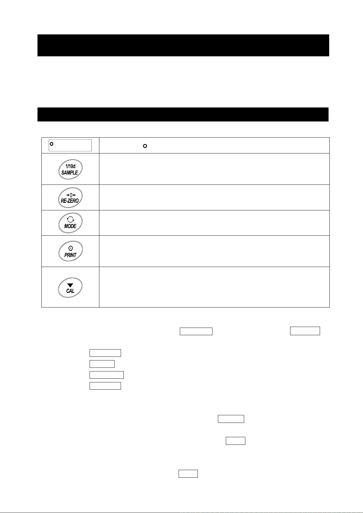
9. Function Table
The function table reads or rewrites the parameters that are stored in the balance. These parameters
are stored in non-volatile memory, even if the AC adapter is removed.
The function table menu consists of two layers. The first layer is the "Class" and the second layer is
the "Item".
9-1 Setting The Function Table
Display symbol and keys
The symbol " " shows that the parameter is enabled.
When pressing and holding the key for 2 seconds in the weighing mode, the
balance enters the function table mode.
The key to select the class or item in the function table mode.
The key to change the parameter.
The key to change the class or item.
When a class is displayed, moves to an item in the class.
When an item is displayed, stores the new parameter and displays the next
class.
When an item is displayed, cancels the new parameter and displays the next
class.
When a class is displayed, exits the function table mode and returns to the
weighing mode.
Setting procedure
1. In weighing mode, press and hold the SAMPLE key for 2 seconds until
displayed.
2. Press the
3. Press the PRINT key to enter the class.
4. Press the RE-ZERO key to change the parameter of the selected item.
5. Press the SAMPLE key to select the item.
6. To change other items of the same class, repeat steps 4 and 5.
To finish changing the parameters of the same class, proceed to step 7.
7. To store the new parameters of the class, press the PRINT key. Then the next class is
SAMPLE key to select a class.
bA5Fnc
is
displayed.
To cancel the new parameters for the class, presss the CAL key. Then the next class is
displayed.
8. To change parameters of another class, continue from step 2.
To finish changing parameters, press the CAL key to return to weighing mode.
57
Page 58

Setting Example
This example shows how to set " Stores the weighing data and sensitivity adjustment history (dAtA 2)"
of "Data memory (dAtA)", and "1 minute (int 5)" of "Interval time (int)".
Step1
Classification item
Step1
Press and hold for 2 seconds
Step2
Step2
Press several times
Step3
Step3
Step4
Press
6 times
Step5,6
Press
several times
Setting item
Setting item
"Data memory function"
"Data memory function"
Step4
Press twice
Setting value
"Store the weighing data"
Step5
Setting value
"Interval time"
Step8
Finish. Weighing display
Step4
Press 4 times
Setting value
"every 1 minute"
Step7
58
Page 59

9-2 Details Of The Function Table
Class Item Description
[00]
ba5fnc
Environment
Display
Cond
Condition
5t-b
Stability band width
Hold
Hold function
trc
Zero tracking
5pd
Display refresh rate
pnt
Decimal point
p-on
Auto display-ON
p-off
Auto display-OFF
Readability
Buzzer
Stores tare value
di5p-led
Backlight brightness
Parameter
0
1
2
0
1
2
0
1
0
1
2
3
0
1
2
0
1
0
1
0
1
0
1
0
1
0
1
0~9
5
Fast response, sensitive value
Slow response, stable value
Stable when within
Stable when within
OFF
ON
OFF
Normal
Strong
Very strong
5 times / second
10 times / second
20 times / second
Point
( . )
Comma
OFF Zero indication at power on
ON Previous time weighing indication at power on
10%~100%
Factory setting 60%
( , )
OFF
ON
OFF
ON
Display readability
Not display readability
OFF
ON
1 digit
±
±
3 digit
Can be changed by response
adjustment. With "
the averaging time.
The stabilization indicator
illuminates with the display
fluctuation within the range.
With "
stabilization range.
Holds the display when stable
in animal mode. With "Hold 1",
ANIMAL turns on.
Keeps zero display by tracking
zero drift.
Output frequency approx.5.21Hz
Output frequency approx.10.42Hz
Output frequency approx. 20.83hz
Decimal point format
Turns on the weighingmode
display when AC adapter is
connected
Turns off the display after
10 minutes of inacticity.
Display at weighing start
Buzzer sound such as
key operation
Hold 1
" , sets the
Hold 1
", sets
Bubble spirit level
lightning
i5d
Impact shock
detection
Cl adj
Clock
Note: "Digit" is a unit of readability.
[01]
OFF
ON
1
0
OFF
ON
1
See "9-7 Clock And Calendar Function"
Factory setting
Bubble spirit level
LED lightning
Impact detection function
(Valid for balance software
version 1.300 or later)
Confirms and sets the time
and date. The time and date
are added to output data.
0
□ The number in [ ] is the classification number. It is output as an identifier when outputting function
table information in batch. Refer to "9-10 Output The Function Table Information".
59
Page 60

Class Item
[02]
Cp fnc
Comparator
Comparator mode
Number of comparator
stages
Near zero
Flow measurement
Cp
Cp-t
Cp-p
Polarity
Cp in
Input method
Cp-frd
Parameter
0
1
2
0
1
0
1
2
3
4
5
0
1
2
0
1
2
3
0
1
Description
No comparison
Comparison when stable value or overloaded
Continuous comparison
3 stage comparator
5 stage comparator
Also compare near zero
5 are not compared
±
are not compared
±10
are not compared
±20
are not compared
±50
100 are not compared
±
Plus only
Minus only
Bipolarity
Digital input, upper / lower limits
Weighing input, upper / lower limits
Digital input, reference value
Weighing input, reference value
Comparison by flow rate value
Comparison by weighing value (g)
HI, OK, LO
HH, HI, OK, LO, LL
HH, Cp Hi, Cp lo
Cp
ll
Cp
Cp ref
can be selected.
,
can be selected.
[03]
Comparator
value
Cp HH
Second upper limit
Cp Hi
Upper limit
Cp lo
Lower limit
Cp ll
Second lower limit
Cp ref
Reference value
Tolerance value
Second tolerance
value
Note: "Digit" is a unit of readability.
See "9-8 Comparator Function"
See "9-8 Comparator Function"
Factory setting
Displayed only
when
Cpin 0 , 1
is set to digital input.
Cp HH , Cp ll
displayed only when 5step
comparator is set.
Displayed only
when
Cpin 2 , 3
is set by input by load.
when 5 step comparator is
set.
is displayed only
are
□ The number in [ ] is the classification number. It is output as an identifier when outputting function
table information in batch. Refer to "9-10 Output The Function Table Information".
60
Page 61
Class Item Description
[04]
bep HH
Cp beep
Comparator
buzzer
HH buzzer
bep Hi
HI buzzer
OK buzzer
bep lo
LO buzzer
bep ll
LL buzzer
[05]
prt
dout
Data output
Data output mode
*
1
Parameter
0
1
0
1
0
1
0
1
0
1
0
1
OFF
ON
OFF
ON
OFF
ON
OFF
ON
OFF
ON
Key mode
Auto print mode A
Reference=zero
(
)
Displayed only when 5 step
comparator is set.
Displayed only when 5 step
comparator is set.
Accepts the PRINT key only when
the display is stable.
Outputs data when the weighing value
stabilizes beyond the range form
to
from the zero point.
ap-b
ap-p
ap-p
Auto print polarity
ap-b
Auto print difference
Auto print mode B
2
Reference=last stable value
(
3
Stream mode
Key mode B (Immediately
4
Key mode C (When stable
5
Interval output mode
6
Plus only
0
Minus only
1
2
Bipolarity
10 digit
0
100 digit
1
1000 digit
2
Outputs data when the weighing
value stabilizes beyond the range
)
from
value.
)
Accepts the PRINT key
regardless of the display
condition.
Accepts the PRINT key
)
immediately when the display is
stable, or waits for the display to
be stable when not.
Outputs data for each time
set by
Displayed value > Reference
Displayed value < Reference
Regardless of displayed value
Difference between reference
value and displayed value
to
ap-p
ap-b
Outputs data at the specified
display refresh rate.
int
.
from last stable
Factory setting
Note: "Digit" is a unit of readability.
□ The number in [ ] is the classification number. It is output as an identifier when outputting function
table information in batch. Refer to "9-10 Output The Function Table Information".
*1 Download "Communication manual" from our website (https://www.aandd.jp) and refer to it.
61
Page 62

Class Item
Parameter
Description
dout [05]
Data output
mode
dAtA
Data memory
Int
Interval time
d-no
Data number
5-td
Time/Date
output
5- id
ID number
output
PU5E
Date output
pause
At-F
Auto feed
Info
GLP output
Ar-d
Zero after
output
UFC *1
UFC function
0 OFF
Stores unit mass in counting
1
mode
Stores the weighing data
and sensitivity adjustment
2
history
Every measurement
0
1 2 seconds
2 5 seconds
3 10 seconds
4 30 seconds
5 1 minutes
6 2 minutes
7 5 minutes
8 10 minutes
0 No output
1 Output
0 No output
1 Time only
2 Date only
3 Time and date
0 No output ID number
1 Output ID number
0 OFF
1 ON open 1.6 seconds
0 OFF
1 ON open 1 line
0 OFF
ON (output with internal
1
clock)
ON (output with external
2
clock)
0 OFF
1 ON
0 OFF
1 ON
Factory setting
Refer to "11.Data
Memory"
Interval time in the interval
memory mode when using
Prt 6.
Valid when data memory
function is ON.
Refer to "9-7 Clock And
Calendar Function".
Selects the data output
interval.
Selects whether or not
automatic feed is
performed.
Refer to "10-3 GLP
Report"
Function to apply re-zero
after outputting data.
Refer to "Communication
manual" on the A&D
website.
Note: “Digit” is a unit of readability.
□ The number in [ ] is the classification number. It is output as an identifier when outputting function
table information in batch. Refer to "9-10 Output The Function Table Information".
*1 Download "Communication manual" from our website (https://www.aandd.jp) and refer to it.
62
Page 63

Class Item
t
Parameter
Description
5 IF [06]
Serial interface
MOdE
Connection
*1
bp5
Baud rate
btpr
Date bit, parity
bit
CrLF
Carriage return
Line feed
TYPE
Data format
T-UP
Timeout
ErCd
AK
Error Code
U5b [07]
Universal serial
bus interface
UFnc
USB function
mode
*1
U-TP
USB data format
0 PC
1 Printer TYPE 0, 1
2 External indicator
Stream output with
TYPE 0
0 600 bps
1 1200 bps
2 2400 bps
3 4800 bps
4 9600 bps
5 19200 bps
6 38400 bps
0 7-bit EVEN
1 7-bit ODD
2 8-bit NONE
0 CRLF ASCll 0Dh code. CR
1 CR
0 A&D standard format
1 DP format
ASCll 0Ah code. LF
Refer to “Communication
manual” on A&D website.
2 KF format
3 MT format
4 NU format
5 CSV format
NU2 forma
6
(Balance software version 1.415 or later)
TAB format
7
(Balance software version 1.415 or later)
0
Not limited
1 Limited to 1 second
Select the wait time during
command reception
0 OFF ASCll 06h code. AK
1 ON
0
Quick USB
(Balance software version 1.211 or later)
1
Bidirectional USB virtual COM
(Balance software version 1.211 or later)
0 A&D standard format
The parameter settings
depend on the balance
software version.
Refer to “Communication
manual” on A&D website.
1 NU format
2 CSV format
3 TAB format
4 NU2 format
Factory setting
Note: “Digit” is a unit of readability.
□ The number in [ ] is the classification number. It is output as an identifier when outputting function
table information in batch. Refer to "9-10 Output The Function Table Information".
*1 Download "Communication manual" from our website (https://www.aandd.jp) and refer to it.
63
Page 64

Class
Class
[10]
ap fnc
Application
function
Item
Item
apf
Application
mode
5taf
Statistical function
mode output items
frd Unit
Flow rate
unit
Ct aUto
Ct aUto
Calculation time
automatic setting
[11]
Minimum
Weighing
Warning
Function
-Cp
Minimum weighing
comparison
Minimum weighing
value input
-t
Minimum weight
tolerance
inout
Minimum weight
out
Unit
[12]
[13]
ld in
Liquid density input
d5
Specific gravity
measuring mode
[14]
[15]
Unit
d5 fnc
Specific gravity
measuring
function
alt
Programmable-unit (Multi-unit)
id
ID number setting
Parameter
Parameter
Normal weighing mode
0
Capacity indicator
1
Statistical calculation mode
2
2
Flow measurement mode
3
3
Gross, Net, Tare mode
4
Number of data, sum
0
0
Number of data,sum,max,min,range(max-min),average
1
1
Number of data,sum,max,min,range(max-min),average,
2
standard deviation,coefficient of variation
Number of data,sum,max,min,range(max-min),average,
3
standard deviation,coefficient of variation,relative error
g / s (gram/second
0
g / m (gram/minute
1
g / h (gram/hour
2
3
mL / s (milliliter/second
mL / m (milliliter/minute
4
mL / h (milliliter/hour
5
OFF
0
1
ON
No comparison Do not use MW Fnc
0
0
Comparison without near zero
1
1
Comparison including near zero
2
2
Refer to "15. Minimum Weighing Warning Function"
0.10%
0
(standard deviation SDx2000
1%
1
(standard deviation SDx200 times)
OFF
0
ON
1
Refer to "4. Weighing"
Water temperature
0
Liquid density
1
Density measurement of a soil
0
Density measurement of a liquid
1
Sets an arbitrary coefficient.
See "17. Programmable-Unit".
Refer to "10-2 Setting The ID Number"
)
)
Description
Description
)
)
)
)
Refer to
"9-9 Description Of
Application"
Refer to "13. Flow
Measurement"
Refer to "15. Minimum
Weighing Warning
Function"
Refer to "18. Density
(Gravity) Measurement"
Available only when
programmable-unit mode
is selected.
Factory setting
Note: "Digit" is a unit of readability.
□ The number in [ ] is the classification number. It is output as an identifier when outputting function
table information in batch. Refer to "9-10 Output The Function Table Information".
64
Page 65

Class Item
PA55wd [16]
Password lock
LOcK
Lock function
PA55NO.
Password
registration
Auto CAL [17]
Automatic
sensitivity
adjustment
*2
CFnc
Sensitivity
adjustment
mode
Ct IME1
Setting Time1
Ct IME2
Setting Time2
Ct IME3
Setting Time3
C Int
Interval time
Ion Fnc [20]
Ionizer function
*3
C5 In [18]
Correction of internal mass
value
*2
Parameter
ADMIN
U5ER 01
U5ER 10
0
OFF
Description
1 ON (Limit weighing operation)
2 ON (Basic weighing is possible)
Administrator password input
USER 1 password input
to
USER 10 password input
0
2
Setting temperature
Setting time
1
Interval time
Refer to
“19. Password Lock
Function”
Refer to “7-1 Automatic Sensitivity Adjustment (GX-AE/GX-A/
GX-AWP Series Only)”
Refer to the instruction manual of “GXA-17 Large Glass Breeze
Break With Ionizer” from our website.
Refer to “7-7-1
Correcting The
Auto Automatic input
Internal Mass Value
Of The GX-AE/GX-A/
GX-AWP Series
(Auto)
Refer to “7-7-2
Correcting The
MANUAL Digital input of correction value
Internal Mass Value
Of The GX-AE/GX-A/
GX-AWP Series
(Manual)
Factory setting
Note. “Digit” is a unit of readability.
□ The number in [ ] is the classification number. It is output as an identifier when outputting function
table information in batch. Refer to "9-10 Output The Function Table Information".
*2 GX-AE/GX-A/GX-AWP series only.
*3 GX-AE series only.
65
Page 66

9-3 Description Of The Class Environment Display
0
0
2
2
0
2
Condition (Cond)
This parameter is for sensitive response to the fluctuation of a mass value. Used for
powder or liquid target mass, weighing a very light sample, or when quick response
weighing is required. After setting to this, the balance displays FAST .
This parameter is for stable weighing with slow response. Used to prevent a mass value
from drifting due to vibration or drafts. After setting to this, the balance displays SLOW .
Stability band width (5t-b)
This item controls the width to regard a mass value as a stable value. When the fluctuation per
second is less than the parameter, the balance displays the stabilization indicator and outputs or
stores the data by function setting ( dout,
mode". Also, the readability
being displayed is 1 digit.
(E.g.) If 0.01 g display is selected by pressing the SAMPLE key on the GX-303A, 0.01 g is 1 digit.
This parameter is used for sensitive response of the stabilization indicator. Used for
exact weighing.
dAtA, etc.). The parameter influences the "Auto print
This parameter ignores slight fluctuations of a mass value. Used to prevent a mass
value from drifting due to vibration or drafts
Hold function (HoLd) (Animal weighing mode)
This function is used to weigh a moving object such as an animal. When the weighing data is over the
weighing range from zero and the display fluctuation is within the stabilization range for a fixed period of
averaging time, the processing indicator illuminates and the balance displays the average weight of the
animal. When the animal or sample is removed from the weighing pan, the display returns to zero
1
automatically. This function is available only when the hold function parameter is set to "
mode indicator HOLD illuminates) and any weighing unit other than the counting mode is selected.
The stabilization range and averaging time are set in "Condition (Cond)" and "Stability band width
(5t-b)".
Weighing range Averaging time Stabilization range
0.0001g model 0.0200g or more
0.001g model 0.200g or more
0.01g model 2.00g or more
0.1g model 20.0g or more
Cond
Cond
Cond
2 sec. (for higher efficiency)
4 sec.
1
8 sec. (for higher accuracy)
5t-b
5t-b
5t-b
1
* Animal weighing pan (GXA-12) can be attached to the models other than GX-203A, GX-124A,
GX-224A, GX-124AE, GX-224AE, GF-203A, GF-124A, GF-224A, GX-203AWP and GF-203AWP.
" (the animal
Lesser 6.25%
12.5%
Greater * 16.7%
Zero tracking (trc)
This function tracks zero point drift caused by changes in the environment and stabilizes the zero
point. The degree of tracking can be selected from 3 levels. If zero is not stable, increase the setting
value. When the weighing data is only a few digits, turn the function off for accurate weighing.
The tracking function is not used. Used for weighing a very light sample.
trc
1
The normal tracking function is used.(±1 digit / 1 second)
trc
The strong tracking function is used. (±1 digit / 0.5 second)
trc
The very strong tracking function is used. (±1 digit / 0.2 second)
3
trc
66
Page 67

Display refresh rate (5Pd)
The periodic time to refresh the display. This parameter influences "Baud rate", "Data output pause" and
the data output rate of "Stream mode".
Decimal point (Pnt)
The decimal point format can be selected.
Auto display-ON (P-on)
When the AC adapter is plugged in, the display is automatically turned on without the ON:OFF
key operation and the balance enters weighing mode. Used when the balance is built into an
automated system. Half an hour warm up (more than one hour for 0.0001g models) is necessary
for accurate weighing.
Auto power-OFF (P-oFF)
This is a function to automatically turn off only the display when there is no operation made for a
certain amount of time (approximately 10 minutes) while the power is on.
Readability (rnG)
When weighing with rough precision, the readability can be turned off without key operation.
This is useful when built into an automated system.
Buzzer (bEEP)
Select ON/OFF for the built-in buzzer that sounds when a key is operated or the status changes.
Tare value record (P-ZEro)
After turning on the power supply, the display will not be automatically set to zero, and it will start
from the previous weighing value. This is useful when a hopper, etc. is attached to the weighing
pan and the power needs to be turned off while weighing discharge.
Backlight brightness (di5P-LEd)
Select the brightness of the backlight of the LCD display.
Bubble sprit level lightning (LV-LEd)
Select ON/OFF for the LED that illuminates the bubble sprit level.
Impact shock detection ( I 5d)
Select ON / OFF for the function to display impact level.
* Applicable from balance software version 1.300 or later.
Even if the function to display impact level is turned off, it is recorded inside the balance when
there is an impact.
9-4 Description Of The Data Output
Download "Communication manual" from our website (https://www.aandd.jp) and refer to it.
9-5 Description Of The Data Format
Download "Communication manual" from our website (https://www.aandd.jp) and refer to it.
9-6 Output Example Of The Data Format
Download "Communication manual" from our website (https://www.aandd.jp) and refer to it.
67
Page 68

9-7 Clock And Calendar Function
The balance is equipped with a clock and calendar function. When the Clock and Calendar function
(dout, 5-td) is set, the time and date are added to the output data.
Set or confirm the time and date as follows:
Operation
1. Press and hold the SAMPLE key for 2 seconds until
is displayed.
2. Press the
SAMPLE key several times to display
3. Press the PRINT key.
The balance enters the mode to confirm or set the time and date.
Confirming the time
4. The current time is displayed with all the digits blinking.
□ To set the clock to the correct time, press the RE-ZERO
key and go to step 5.
□ To confirm the date, press the SAMPLE key and
go to step 6.
□ To finish setting, press the CAL key and go to step 8.
bA5Fnc
CLAdJ
.
Press and hold
for 2 seconds
Press several times
Comfirm the time
Setting the time
5. Set the time in 24-hour format using the following keys.
RE-ZERO (+) key ꞏꞏ Changes the value of the selected
(blinking) digit.
MODE (-) key ꞏꞏꞏꞏꞏꞏꞏ Changes the value of the selected
(blinking) digit.
SAMPLE key ꞏꞏꞏꞏꞏꞏꞏ Selects the digit to blink.
PRINT key ꞏꞏꞏꞏꞏꞏꞏꞏꞏꞏꞏ Stores the new time setting and
displays End and goes to step 6.
CAL key ꞏꞏꞏꞏꞏꞏꞏꞏꞏꞏꞏꞏꞏ Cancels the new setting and
goes to step 6.
Confirming the date
6. The current date is displayed with all the digits blinking.
□ To change the order of year [last two digits] (Y),
M
month (
date will be output in the specified order.
□ To set the calendar to the correct date, press the
RE-ZERO key to go to step 7.
□ To finish setting, press the CAL key to go to step 8.
□ To confirm the time again, press the SAMPLE key
to go to step 4.
) and day (d), press the MODE key. The
Set the time
Store the time
Comfirm the date
Set the date
Store the date
68
Page 69

Setting the date
7. Set the date using the following keys. (The year is set with the last 2 digits of the year as per
Western calendar)
RE-ZERO (+) key ꞏ Changes the value of the selected (blinking) digit.
MODE (-) key ꞏꞏꞏꞏꞏꞏ Changes the value of the selected (blinking) digit.
SAMPLE key ꞏꞏꞏꞏꞏꞏꞏ Selects the digit to blink.
PRINT key ꞏꞏꞏꞏꞏꞏꞏꞏꞏꞏ Stores the new setting, displays
CAL key ꞏꞏꞏꞏꞏꞏꞏꞏꞏꞏꞏꞏꞏ Cancels the new setting and goes to step 8.
End
, and goes to step 8.
Finishing setting
8. The balance displays the next menu (CP Fnc) of the function table. Press the CAL key to exit
the clock and calendar function and return to the weighing mode.
Note
Do not enter invalid values such as a non-existing date when setting the time and date.
The balance displays
the clock and calendar function. The clock and calendar function works normally if the balance is
powered with the AC adapter. Set the time and date using the keys.
rtc PF
when the clock backup battery has been depleted, but It only affects
69
Page 70

9-8 Comparator Function
For comparison using the comparator function, either 3-stage or 5-stage can be selected (CP Fnc,
CP-t). The 3-stage comparator is selected by default, and the HI / OK / LO indicator will be
displayed according to the result of comparison. When the 5-stage comparator is selected, HH and LL
become available with the HI and LO indicators respectively displayed blinking.
With the optional GXA-04, comparison results can be output to the contact.
There are three operating ranges:
No comparison
Comparison when stable or overloaded
Continuous comparison
There are six levels of conditions for comparing near zero, from "including near zero" to "± 100 digits".
The criteria for comparison are "upper limit and lower limit value" and "reference value and tolerance
range".
There are two ways to input the values: "digital input" and "input by sample load".
Refer to the function table
With the function table CP bEEP
comparison result.
CP Fnc
.
, it is also possible to sound a built-in buzzer according to the
3-stage comparison result
Threshold value
Weighing value
Upper limit
Lower limit
Judgment formula
Upper limit value
Lower limit value
Weighing value
<
Weighing value Upper limit value
≦
Weighing value Lower limit value
5-stage comparison result
Threshold value
Second upper limit
Second lower limit
Note
Weighing value
Judgment formula
2nd
Upper limit value
Upper limit value
Upper limit
Lower limit value
Lower limit
2nd
Lower limit value ≦<Weighing value Lower limit value
<
Weighing value
Weighing value
<
≦
Weighing value
Weighing value
□ In the flow measurement mode (
flow rate values.
If CP-Frd of the Function table is set to CP Fnc "1", comparison of weighing values (g) is also
possible.
3-step comparison - display
Buzzer
control
Buzzer
control
≦
<
2nd
≦
Upper limit value
≦
Upper limit value
2nd
<
Lower limit value
Judgment
result
OK
5-step comparison - display
Judgment
result
HI
LO
Lit display
HI
OK
LO
Lit display
HH
HI
OK
LO
HI
OK
LO
LL
Blinking
display
Blinking
display
HI
LO
) by default, the comparator function makes comparison of
70
Page 71

Selecting the comparator (3-stage/5-stage)
1. Press and hold the SAMPLE key for 2 seconds until
bA5Fnc
2. Press the SAMPLE key several times to display
3. Press the PRINT key.
4. Press the SAMPLE key several times to display
of the function table is displayed.
CP Fnc .
CP-t .
Press and Hold
for 2 seconds
Press several times
2
0
all
Press several times
l
5. Press the RE-ZERO key to select “0” for 3-stage comparator
or “1” for 5-stage comparator. Press the PRINT key to set.
6. Press the CAL key to return to the weighing mode.
1
l
71
Page 72

Setting example 1
Continuous comparison except near zero ± 20 digits. Reference / tolerance. Digital input.
Selecting a comparison method (operating range, comparison criteria, and value input)
(with the 3-stage comparator)
1. Press and hold the SAMPLE key for 2 seconds until
bA5Fnc of the function table is displayed.
2. Press the SAMPLE key several times to display
CP Fnc .
3. Press the PRINT key.
4. Press the RE-ZERO key several times to display
CP ALL ( "2" for continuous comparison).
5. Press the SAMPLE key several times to display
CP-Z .
6. Press the RE-ZERO key several times to display
CP-Z Ex
7. Press the SAMPLE key several times to go into the
CP in item.
8. Press the RE-ZERO key several times to display
CP in rFE
9. Press the PRINT key to store the selected method.
20d
( "3" for ± 20 are not compared).
G
D1
( "2" for reference value, digital input).
72
Page 73

Entering the values
10. With CP VALUE displayed, press the PRINT key.
11. CP rEF
12. Press the PRINT key.
13. The currently set value is displayed with all the
digits blinking.
To continue with the set value, press the PRINT or
CAL key to go to step 14.
To change the set value, press the RE-ZERO key.
Use the following keys:
SAMPLE key ꞏꞏꞏ Selects the digit to change the value.
RE-ZERO key ꞏ Changes the value of the selected digit.
MODE key ꞏꞏꞏꞏ Reverses the polarity.
PRINT key ꞏꞏꞏꞏ Stores the new vale and goes to
CAL key ꞏꞏꞏꞏꞏꞏꞏꞏ Cancels the new vale and goes to
14. When CP LMt is displayed, pressing the PRINT key
displays the currently set value.
To change the set value, use the following keys and store
a tolerance value.
For the tolerance range, enter a value with the reference
value as 100%.
SAMPLE key ꞏꞏꞏꞏꞏꞏꞏ Selects the digit to blink.
RE-ZERO (+) keyꞏꞏ Changes the value of the selected
MODE (-) key ꞏꞏꞏꞏꞏꞏ Changes the value of the selected
PRINT key ꞏꞏꞏꞏꞏꞏꞏꞏꞏꞏ Stores the new value and goes to step 15.
CAL key ꞏꞏꞏꞏꞏꞏꞏꞏꞏꞏꞏꞏꞏꞏ Cancels the new value and goes to step 15.
15. Press the CAL key twice to return to the weighing mode.
appears.
step 14.
step 14.
(blinking) digit.
(blinking) digit.
73
Page 74

Setting example 2
Comparison when stable or overloaded including near zero. Upper/lower limits. Weighing input.
Selecting a comparison method (operating range, comparison criteria, and value input)
(with the 3-stage comparator)
1. Press and hold the SAMPLE key for 2 seconds until
bA5Fnc of the function table is displayed.
2. Press the SAMPLE key several times to display
CP Fnc .
Press and hold
for 2 seconds
3. Press the PRINT key.
Press several times
4. Press the RE-ZERO key several times to display
CP S
tA
b
("1" for comparison when stable or overloaded).
5. Press the SAMPLE key several times to display
6. Press the RE-ZERO key several times to display
("0" for also compare near zero).
7. Press the SAMPLE key several times to display
8. Press the RE-ZERO key several times to display
(" 1 " for weighing input, upper/lower limits).
9. Press the PRINT key to store the new setting.
CP-Z
CP in
.
CP - Z
I
CP in H/L
N
.
3
WT
0
all
Press several times
S
tab
Press several times
20d
Z
Press several times
Z
Press several times
74
2
Press several times
1
Page 75

Entering the reference and tolerance values
10. When CPVALUE displayed, press the PRINT key to
display CP Hi .
11. When CP Hi is displayed, press the PRINT key to
check the currently set value (all digits blinking).
Press the RE-ZERO key to enter the load input mode.
g
12. Press the RE-ZERO key, 0.00
a sample of the weight of the upper limit on the balance and
press the PRINT key. (Register the upper limit value.)
13. When finished, CP Lo is displayed. (Replace a sample of
the weight of the upper limit from the balance.)
14. When CP Lo is displayed, press the PRINT key to
check the currently set value (all digits blinking). Press the
RE-ZERO key to enter the load input mode.
15. Press the RE-ZERO key, 0.00
16. Place a sample of the weight of the lower limit on the
balance and press the PRINT key. (Register the lower
limit value.)
17. When finished, CP Hi is displayed. (Replace a sample of
the weight of the lower limit from the balance.)
18. Press the CAL key twice to return to the weighing display.
is displayed. Place
g
is displayed.
75
Page 76

Sounding the built-in buzzer according to the comparison result.
1. Press and hold the SAMPLE key for 2 seconds until
bA5Fnc of the function table is displayed.
2. Press the SAMPLE key several times to display
CP bEEP .
3. Press the PRINT key.
4. Press the SAMPLE key to set ON/OFF of the
buzzer sound for the comparison judgment result.
When the 3-stage comparator is set, the following
three options are available:
bEP Hi bEP oK
bEP Lo .*
When the 5-stage comparator is set, the following
five options are available:
bEP HH bEP Hi bEP oK
bEP Lo
bEP LL .*
SAMPLE key ꞏꞏꞏꞏꞏ Selects the comparison
judgment result.
RE-ZERO key ꞏꞏꞏꞏ Sets ON/OFF of the buzzer
sound for the comparison
judgment result.
PRINT key ꞏꞏꞏꞏꞏꞏꞏꞏ Stores the settings.
5. Press the PRINT key to store the buzzer sound
settings for the comparison judgment results.
After End is displayed, dout
appears.
6. Press the CAL key to return to weighing mode.
* Regarding the setting of the comparator stage CP-t ,
refer to “Selecting the comparator (3-stage and 5-stage)"
on page 71.
0
0
0
Press and Hold
for 2 seconds
Press several times
1
1
1
dout
76
Page 77

9-9 Description Of Application
Description of the normal weighing mode (APF 0).
This mode is set at the factory setting.
Description of the capacity indicator mode (APF 1).
In normal weighing, the weighing capacity indicator shows the relationship between the load and
weighing capacity as a percentage.
(Zero 0%, weighing capacity 100%)
Note:
□ It cannot be used when "dAtA 1“ or “dAtA 2" of the data memory function (dAtA
) is set..
Description of the statistical calculation mode (ApF 2).
This mode statistically calculates the weight data and displays/outputs the results.
For details, refer to "12. Statistical Calculation Mode".
Description of the flow measurement mode (APF 3).
This mode calculates the flow rate (change of weighing value with time).
For details, refer to "13. Flow Measurement".
Description of the gross, net, and tare mode (APF 4).
Zero setting and taring can be performed separately, and gross (total amount), net (net amount),
and tare (tare amount) data can be output.
For details, refer to "14. Gross Net Tare Function".
77
Page 78

9-10 Output The Function Table Information
With function table, you can set the balance's operation to that appropriate for how it is used.
In the menu structure of the function table, setting items are included in each class, and a parameter is
registered for each item. The function table information can be output in batch by the following
operation so that the settings when the balance is used can be recorded.
Note
Available with balance software version 1.300 or later.
Procedure for batch outputting of function table information
1. Press and hold the SAMPLE key for 2 seconds
in the weighing mode.
2. bA5Fnc is displayed.
3. Press and hold the PRINT key for 2 seconds.
- L i5t -
information is output in batch.
Example of output
appears and the current function table
ⓐ ⓑ
ⓐ ⓑ
ⓐ ⓑ
ⓐ ⓑ
Model name
Serial number
ID
Date
Time
Outputs date and time of the balance
a. Class number (2 characters)
ⓒ
ⓒ
ⓒ
…
…
…
…
b. Item (8 characters)
c. Parameter (2 or 12 characters)
* Divided by a comma.
Refer to "9-2 Details Of The Function Table" for class
numbers, items and parameters.
78
Page 79

Output example 1 Outputting the function table settings to a printer
For printing, please use an AD-8127 multi-printer.
1. Connect the balance and the printer.
When using the AD-8127, set the print mode to "DUMP". For details about the settings and print
mode, refer to the instruction manual of the printer. For connection between the balance and the
printer, refer to "Communication manual" on A&D website (https://www.aandd.jp).
2. Make sure that communication is possible between the balance and the printer, and then perform
the output operation according to the previous section “Procedure for batch outputting of function
table information”.
Output example 2 Outputting the function table settings to a computer
For USB setting and WinCT software, please refer to "Communication manual" and "WinCT Operation
Manual" on our website (https://www.aandd.jp).
1. Connect the balance and a PC with the supplied USB cable or RS-232C cable (sold separately).
When using the USB, use it in the virtual COM mode. It is not possible to output with Quick USB.
2. Install WinCT software on the PC.
WinCT can be downloaded from our website (https://www.aandd.jp).
3. Start RSCom and match the communication settings such as COM port and baud rate with the
balance. Clicking the [Start] button enables communication.
4. Make sure that communication is possible between the balance and the PC, and then perform the
output operation according to the previous section “Procedure for batch outputting of function table
information”.
79
Page 80

10. ID Number And GLP Report
10-1 Main Objective
□ The data output compliant with "GLP/GMP" can be output to a personal computer or optional printer using
the RS-232C serial interface.
□ The GLP/GMP compliant report includes the balance manufacturer (A&D), model name, serial
number, ID number, date, time, and space for signature. For a sensitivity adjustment or calibration
test, the result and the weight used are also included.
□ The balance can output the following GLP/GMP compliant reports via the RS-232C or USB.
Sensitivity adjustment report for sensitivity adjustment using the internal mass [automatic
sensitivity adjustment]
Sensitivity adjustment report for sensitivity adjustment using an external weight
Calibration test report for calibration test using an external weight
Breaks (“title block" and "end block") for easy management of a series of weighing data
□ Changing the function table enables the balance to store sensitivity adjustment report and
calibration test temporarily in data memory in order to output all at once. For the setting, refer to
"11. Data Memory".
□ The ID number can be used as an identification number for the balance during maintenance of the
balance.
□ The ID number is stored in non-volatile memory even if the AC adapter is removed, and is valid
until a new registration is made.
□ For confirmation and setting of the time and date, refer to "9-7 Clock And Calendar Function".
□ When printing GLP output with an AD-8127 multi-printer connected to the balance, the clock
2
function of the printer can be used to print the time and date. (Function table "
(Balance software version 1.211 or later)
Centralized management using the password lock function on the AD-8127 side is effective in
preventing time and date tampering.
Note
To output GLP/GMP compliant reports, set the print mode of the AD-8127 to the dump print mode.
If the external key print mode is set for weighing value printing, press and hold the ENT key of
the AD-8127 for 2 seconds to switch between the external key print mode and dump print mode.
inFo
")
10-2 Setting The ID Number
1. Press and hold the SAMPLE key for 2 seconds until bA5Fnc of the function table is
displayed.
2. Press the SAMPLE key several times to display id .
3. Press the PRINT key. Set the ID number using the following keys.
SAMPLE key ꞏꞏꞏꞏꞏꞏꞏꞏꞏꞏꞏꞏꞏꞏꞏꞏꞏꞏꞏꞏꞏꞏꞏꞏꞏꞏ Selects the digit to blink.
RE-ZERO key, MODE key ꞏꞏꞏꞏ Changes the character of the selected (blinking) digit.
PRINT key ꞏꞏꞏꞏꞏꞏꞏꞏꞏꞏꞏꞏꞏꞏꞏꞏꞏꞏꞏꞏꞏꞏꞏꞏꞏꞏꞏꞏꞏ Stores the new ID number and displays PA55wd .
CAL key ꞏꞏꞏꞏꞏꞏꞏꞏꞏꞏꞏꞏꞏꞏꞏꞏꞏꞏꞏꞏꞏꞏꞏꞏꞏꞏꞏꞏꞏꞏꞏꞏ Cancels the new ID number and displays PA55wd .
4. With PA55wd displayed, press the CAL key to return to weighing mode.
80
Page 81

Note
There are four types of segment displays on the
balance display.
For each type of segment display, refer to the
display correspondence table below.
7 segment 15 segment
Display correspondence table
11 Segment
0123456789
7 Segment
0123456789
0123456789
14 Segment
0123456789
0123456789
0 1 2 3 4 5 6 7 8 9 -
15 Segment
0123456789
0123456789
ABCDEFGH
-
Space
ABCDEFGH
ABCDEFGH
-
-
Space
Space
ABCDEFGH
ABCDEFGH
-
-
A B C D E F G H I J
Space
Space
ABCDEFGH
ABCDEFGH
-
-
I
JKLM
I
JKLM
JKLM
I
I
JKLM
JKLM
K L M N O P Q
I
JKLM
JKLM
14 segment
11 segment
NOPQRSTUVWXYZ
NOPQRSTUVWXYZ
NOPQRSTUVWXYZ
N
NOPQRSTUVWXYZ
R S T U V W X Y Z
NOPQRSTUVWXYZ
NOPQRSTUVWXYZ
Space
Space
10-3 GLP Report
To output GLP/GMP data and the like with an AD-8127 multi-printer or PC, set to "
clock data built into the balance) or "
table.
Note
□ If the date/time is incorrect with “
date/time with "
inFo 2
□ "
" parameter setting is available with balance software version 1.211 or later.
CL AdJ
inFo 2
" (output the clock data of the external device) in the function
inFo 1
" (Clock) of the function table.
(use the clock data built into the balance), adjust the
“
inFo 1
" (output the
81
Page 82
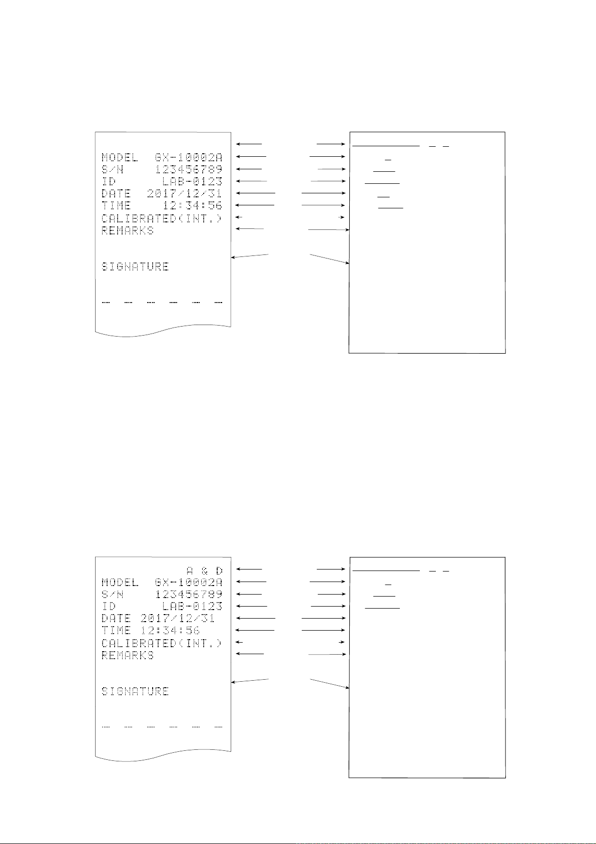
Examples of sensitivity adjustment report using the internal mass
r
r
r
___
r
r
___
This is the GLP report when the sensitivity of the balance is adjusted using the internal mass.
□ Output the clock data built into the balance (info 1)
Printer format (AD-8127) PC format (RsCom)
A&D
□ Output the clock data of the external device (info 2).
Space, ASCII 20h
<TERM> Terminator, CR LF or CR
CR Carriage return, ASCII 0Dh
LF Line feed, ASCII 0Ah
When outputting data such as that for GLP/GMP, setting the function table "info 2" enables use of the
clock data of the external device such as a PC or printer instead of the clock data built into the balance.
Use this function to unify clock data with the clock function of an external device.
Note
Manufacture
Model
Serial numbe
ID numbe
Date
Time
Sensitivity adjustment type
Remarks
Signature
A & D<TERM>
MODEL GX-10002A<TERM>
S/N 123456789<TERM>
ID LAB-0123<TERM>
DATE 2017/12/31<TERM>
TIME 12:34:56<TERM>
CALIBRATED(INT.)<TERM>
REMARKS<TERM>
<TERM>
<TERM>
SIGNATURE<TERM>
<TERM>
<TERM>
----------------
<TERM>
<TERM>
<TERM>
□ The function to output the clock data of external devices can be used with devices that have a clock
function and can output the date and time in response to <ESC>D and <ESC>T. (e.g. AD-8127 multi
printer, RsCom [WinCT])
□ For sensitivity adjustment history storage of the data memory function, the clock data built into the
balance is saved even when
"info 2" is set.
Printer format (AD-8127) PC format (RsCom)
Manufacture
Model
Serial numbe
ID number
Date
Time
Sensitivity adjustment type
Remarks
Signature
A & D<TERM>
MODEL GX-10002A<TERM>
S/N 123456789<TERM>
ID LAB-0123<TERM>
2017-12-31<TERM>
12:34:56<TERM>
CALIBRATED(INT.)<TERM>
REMARKS<TERM>
<TERM>
<TERM>
SIGNATURE<TERM>
<TERM>
<TERM>
---------------<TERM>
<TERM>
<TERM>
Space, ASCII 20h
<TERM> Terminator, CR LF or CR
CR Carriage return, ASCII 0Dh
LF Line feed, ASCII 0Ah
82
Page 83

Calibration test report using the internal mass (0.0001g models only)
This is the GLP report when checking the weighing accuracy of the balance with the internal mass.
(Adjustment is not performed).
When "inFo 1" is set.
Printer format (AD-8127)
A & D
MODEL GX-324A
S/N 123456789
ID LAB-0123
DATE 2017/12/31
TIME 12:34:56
CAL.TEST(INT.)
ACTUAL
0.0000 g
+199.9999 g
TARGET
+200.0000 g
REMARKS
SIGNATURE
Manufacturer
Model
Serial number
ID number
Date
Time
Calibration test
Zero point value
Target weight
value
Target weight
Remarks
Signature
PC format (RsCom)
A & D
MODEL GX-324A
S/N 123456789
ID
DATE
TIME
LAB-0123
2017/12/31
12:34:56
CAL.TEST(INT.)
ACTUAL<TERM>
0.0000 g
+199.9999 g
TARGET
<TERM>
+200.0000 g
REMARKS
<TERM>
<TERM>
<TERM>
SIGNATURE
<TERM>
<TERM>
<TERM>
<TERM>
<TERM>
<TERM>
<TERM>
<TERM>
<TERM>
<TERM>
<TERM>
<TERM>
<TERM>
<TERM>
CR
LF
Space, ASCII 20h
Terminator, CR LF or CR
Carriage return, ASCII 0Dh
Line feed, ASCII 0Ah
83
Page 84

Sensitivity adjustment report using an external weight
r
r
___
This is the GLP report when the sensitivity of the balance is adjusted using an external weight.
When “
info 1
“ is set.
Printer format (AD-8127) PC format (RsCom)
A & D
MODEL GX-10002A
S/N 123456789
ID LAB-0123
DATE 2017/12/31
TIME 12:34:56
CALIBRATED(EXT.)
CAL.WEIGHT
+10000.00 g
REMARKS
SIGNATURE
Space, ASCII 20h
<TERM> Terminator, CR LF or CR
CR Carriage return, ASCII 0Dh
LF Line feed, ASCII 0Ah
Manufacture
Model
Serial numbe
ID number
Date
Time
Sensitivity adjustment type
Sensitivity adjustment weight
Remarks
Signature
A & D
MODEL GX-10002A
S/N 123456789
ID
DATE
TI ME
LAB-0123
2017/12/31
12:34:56
CALIBRATED(EXT.)
CAL.WEIGHT
<TERM>
+10000.00 g
REMARKS
<TERM>
<TERM>
<TERM>
SIGNATURE
<TERM>
<TERM>
<TERM>
---------------<TERM>
<TERM>
<TERM>
<TERM>
<TERM>
<TERM>
<TERM>
<TERM>
<TERM>
<TERM>
<TERM>
Calibration test report using an external weight
This is the GLP report when checking the weighing accuracy of the balance with an external weight.
(Adjustment is not performed)
When “
info 1” is set:
Printer format (AD-8127)
A & D
MODEL GX-10002A
S/N 123456789
ID LAB-0123
DATE 2017/12/31
TIME 12:34:56
CAL.TEST(EXT.)
ACTUAL
0.00 g
+9999.95 g
TARGET
+10000.00 g
REMARKS
SIGNATURE
Space, ASCII 20h
<TERM>
Terminator, CR LF or CR
Carriage return, ASCII 0Dh
CR
LF
Line feed, ASCII 0Ah
Manufacturer
Model
Serial number
ID number
Date
Time
Calibration test
Zero point value
Target weight
value
Target weight
Remarks
Signature
PC format (RsCom)
A & D
MODEL GX-10002A
S/N 123456789
ID
DATE
TIME
LAB-0123
2017/12/31
12:34:56
CAL.TEST(EXT.)
ACTUAL<TERM>
0.00 g
+9999.95 g
TARGET
<TERM>
+10000.00 g
REMARKS
<TERM>
<TERM>
<TERM>
SIGNATURE
<TERM>
<TERM>
<TERM>
<TERM>
<TERM>
<TERM>
<TERM>
<TERM>
<TERM>
<TERM>
<TERM>
<TERM>
<TERM>
84
Page 85

Title block and End block
Application / Operation
“Title block” and “End block” can be added before and after a series of weighing values for data
management.
Pressing and holding the PRINT key for 2 seconds outputs "Title block" and "End block"
alternately.
Note
If the data memory function is used, Title block and End block cannot be output.
Output method using the keys
1. With the weighing value displayed, press and hold the PRINT key for 2 seconds until
5tArt is displayed to output "Title block".
2. Output the weighing value. The output method depends on the setting of the data output mode.
3. Press and hold the PRINT key for 2 seconds until rEc End is displayed to output "End
block".
85
Page 86

11. Data Memory
Data memory is a function to store in the balance unit masses for counting mode, weighing results,
sensitivity adjustment results, etc., and afterward to perform data confirmation or batch output.
The following six types of data can be stored.
1. Unit mass (Counting mode) Up to 50 sets
2. Weighing value
Sensitivity adjustment report
3. Internal mass sensitivity adjustment
4. External weight sensitivity adjustment
Calibration test report
5. Internal mass calibration test (0.0001g models only)
6. External weight calibration test
Up to 200 sets
Latest 50 sets
11-1 Data Memory For Weighing Data
Features
□ Weighing results can be stored in the internal memory of the balance.
□ The balance can store weighing results so that you can continue weighing work without a printer or
a personal computer connected.
□ The balance can store weighing results so that you can perform weighing work without occupying
a printer or PC for a long time.
□ Stored data can be displayed on the balance for data confirmation.
□ Stored data can be output in batch (to a PC or optional printer). The output format and whether to
add a data number, time/date, and ID number can be selected with the function table.
□ The balance has a capacity to store up to 200 weighing results with timestamp.
* For how to store unit masses, refer to "4-3 Counting Mode (PCS)".
Storing the weighing results and sensitivity adjustment results
1. Set the "Data memory (dAtA)" of the function table to "Stores weighing data and sensitivity
adjustment history (dAtA 2)". Refer to "9. Function Table" and the following “Enabling data
memory function”.
2. With "Time/Date output (5-td)" of the function table, set whether to add timestamp.
3. How to store the weighing results depends on the operation of "Data output mode (Prt)" of the
function table.
Note
When Prt 3 (stream mode) is set, data may not be stored correctly.
* The time and date settings can be changed after the weighing values are stored.
86
Page 87

Enabling data memory function
1. Press and hold the SAMPLE key for 2 seconds until
bA5Fnc is displayed.
2. Press the SAMPLE key several times to display
dout .
3. Press the PRINT key.
4. Press the SAMPLE key several times to display dAtA .
5. Press the RE-ZERO key to display
2
.
6. Press the PRINT key to store the setting.
7. Press the CAL key to return to the weighing mode.
Press and hold
for 2 seconds
Press
several times
prt
Press
several times
2
Display and symbol
Number of stored data
Full memory
Data number of the
displayed weighing
value
Weighing display in
progress
Display of measured weighing
value
When the volume of measured
values stored reaches its
maximum,
blink in turn.
FUL
dAt
Caution
□ When weighing data is being stored in memory, the data is output simultaneously using RS-232C
or USB interface.
□ "FUL" indicates that memory is full or the memory capacity has been reached. More data cannot be
stored unless the stored data is deleted.
□ When the interval output mode is operating, automatic sensitivity adjustment due to temperature
change is not performed.
□ The statistical calculation function cannot be used while the data memory function is being used.
87
Page 88

Setting the function table
A
b
d
d
d
d
d
d
Parameter settings for each output mode are as follows:
No
Data
memory
function
dAtA 2
dAtA 2
dAtA 2
dAtA 2
dAtA 2
dAtA 2
Interval time
Not used
int 0
5-t
5-t
5-t
5-t
8
to
0
-
1
2
3
Up to 200
sets
Auto print
Item
Mode
Key mode
Auto print mode A
Auto print mode B
Key mode B (immediate)
Key mode C (stable)
Interval output mode
Parameter settings for Data number, ID number, Time/Date
No
Data number
Yes
No
ID number
Yes
Data output
mode
Prt 0
Prt 1
Prt
Prt 4
Prt 5
Prt 6
d-no
d-no "1
5- i
"0" Date only
5- i
"1" Both
2
0
"
"
" Time only
polarity,
difference
Not used
AP-
0
AP-
0
Not used
Time/Date
to
to
2
2
Displaying the stored weighing results
Note
Confirm that the "Data memory (dAtA)" parameter is set to "Stores the weighing data and sensitivity
adjustment history (dAtA 2)".
1. Press and hold the PRINT key for 2 seconds until
RECALL is displayed.
Left of the display
"- d - or d - t" [types of weighing results] appears in the
upper left of the display.
2. Press the PRINT key to enter the memory recall mode.
Operate the following keys.
RE-ZERO key
MODE key
PRINT key
CAL key
3. Press the CAL key to return to the weighing mode.
* The time and date output settings can be changed after the weighing values are stored.
.....
..........
...........
..............
Displays the next data set.
Displays the previous data set.
Outputs the displayed data via RS-232C or USB.
Exits the memory recall mode.
88
When setting without clock / date
When setting with clock / date
or
Page 89

Outputting stored weighing results in batch
Note
In order to output in batch, "Serial interface (5
I F)" of the function
table must be configured. Refer to "9. Function Table" and
"Communication manual" on A&D website
(https://www.aandd.jp).
1. Press and hold the PRINT key for 2 seconds until
RECALL is displayed.
2. Press the SAMPLE key to display
3. Press the PRINT key to display
out
blinking.
4. Press the RE-ZERO key to display
"Go" blinking.
5. Press the PRINT key to output the stored data all at once
via RS-232C/USB.
6. The balance displays CLEAR when the output is completed.
Press the CAL key to return to the weighing mode.
out
out
No
.
with "No"
Go
with
Press and hold
for 2 seconds
Deleting the stored weighing results in batch
1. Press and hold the PRINT key for 2 seconds until
RECALL is displayed.
2. Press the SAMPLE key several times to display
CLEAR .
CLEAR
No
Go
3. Press the PRINT key to display
CLEAR
with ”No“ blinking.
4. Press the RE-ZERO key to display
with ”Go“ blinking.
5. Press the PRINT key to delete all the stored data.
6. The balance displays End when the deletion is
Press and hold
for 2 seconds
Press
several times
completed, then returns to the weighing mode.
89
Delete at once
Page 90

11-2 Data Memory For Sensitivity Adjustment And Calibration
Test
Features
□ The results of sensitivity adjustment (with the internal mass/an external weight) results and
calibration test results can be stored in the internal memory of the balance.
□ The stored results can be output (to an optional printer or personal computer) in batch.
□ The balance has a capacity to store up to 50 sensitivity adjustment /calibration test results.
* When the memory capacity of up to 50 sets has been reached,
FUL
"
" "
CAL
" indicators blink in turn.
Upper left of the display
Storing the sensitivity adjustment and calibration test results
1. Set the "Data memory (dAtA)" parameter to "Stores weighing data and sensitivity adjustment
history (dAtA 2)". Refer to "9 Function Table".
2. With the settings above, each time sensitivity adjustment or calibration test is performed, the
data is stored automatically.
90
Page 91

Outputting sensitivity adjustment history
1. In the weighing mode, press and hold the CAL key
for 2 seconds. When CAL Hi5 is displayed, release
your finger from the key. out appears.
If there is no sensitivity adjustment history,
is displayed, then the display returns to the weighing
mode.
2. Press the PRINT key to display
3. Switch
display
4. With
No
out
out
Go
/
Go
with the RE-ZERO key to
Go
.
displayed, press the PRINT key to
out
start output in batch.
The output format is compliant with "GLP output".
5. When output is completed, End is displayed, and then CLEAR
appears.
6. To delete saved histories all at once, go to following "Deleting
sensitivity adjustment history".
To return to the weighing values, press the CAL key.
* If the
FUL
CAL
indicators are blinking in turn with
weighing display, 50 sets of data have been already stored in
memory.
If a new result is saved in this state, the oldest data will be
overwritten. Delete some of the saved data.
No dAtA
No
When there is no sensitivity adjustment history
.
Press and hold
for 2 seconds
Release
Batch output
91
Page 92

Deleting sensitivity adjustment history
1. Press and hold the CAL key for 2 seconds.
When CAL Hi5 is displayed, release the key.
oout
appears.
2. Press the
SAMPLE key to display
CLEAR
3. Press the
PRINT key to display
CLEAR No
4. Press the RE-ZERO key to toggle between
No
/ Go to display
5. With
CLEAR
Go displayed, press the PRINT
key to start deleting all at once.
6. When deletion is completed, the balance displays
End
and returns to the weighing mode.
CLEAR
Go .
Press and hold for 2 seconds
Release
.
.
Deleting
92
Page 93

12. Statistical Calculation Mode
The statistical calculation mode statistically calculates the weight data, and displays or outputs the
results. To use the statistical calculation mode, set the "Application function (APF)" parameter of
2
“Application (AP Fnc)" in the function table to "
mode (factory setting), set "Application mode (APF)" to "0".
Statistical items available are number of data, sum, maximum, minimum, range (maximum-minimum),
average, standard deviation, coefficient of variation, and relative error. What statistical items to output
can be selected from the four modes in the function table (5tAF).
□ The wrong data input can be canceled by the key operation, if immediately after the input.
□ Turning the balance off will delete the statistical data.
□ The standard deviation, coefficient of variation, and relative error are obtained by the equation
below:
Standard deviation=
Standard deviation
Coefficient of variation (CV)=
Average
Relative error of maximum value =
Minimum value
Relative error of minimum value =
Note
□ When there is data with a readability digit off, the calculation result is displayed with the
readability digit off. (Readability digit is rounded off.)
□ When the data memory function is in use, the statistical calculation function cannot be used.
□ When registering the warning function of the minimum weighing value, the statistical
calculation function cannot be used.
", as described below. To return to the normal weighing
where Xi is the i-th weight data,
N is number of data.
x 100 (%)
-
Maximum value
Average
Average
Average
-
Average
x 100 (%)
x 100 (%)
12-1 How To Use The Statistical Calculation
Switching to the statistical function mode
(Changing the function table)
1. Press and hold the SAMPLE key for 2 seconds until
bA5Fnc is displayed.
2. Press the SAMPLE key several times to display
AP Fnc .
3. Press the PRINT key to display .
4. Press the RE-ZERO key several times to display
.
To select statistical items to output, go to step 5.
To store the statistical function mode settings, go to 7.
To disable the statistical calculation mode, press the
RE-ZERO key to select
.
Press and hold
for 2 seconds
Press several times
Press several times
Store the setting
Go to 7
Set the flow rate unit
Go to 5
93
Page 94

Selecting the statistical items to output
5. Press the SAMPLE key to display .
6. Press the RE-ZERO key to select the output items.
In the example, the number of data, sum, maximum,
minimum, range (maximum - minimum) and average are
selected as the output items.
Parameter Description
0
Number of data, sum
Continue from Step 4
1
2
3
7. Press the PRINT key to store the setting.
8. Press the CAL key to return to the weighing mode.
Number of data, sum, maximum, minimum,
range (maximum – minimum), average
Number of data, sum, maximum, minimum,
range (maximum – minimum), average,
standard deviation, coefficient of variation
Number of data, sum, maximum, minimum,
range (maximum – minimum), average,
standard deviation, coefficient of variation, relative
error of maximum value, relative error of minimum value
Selecting the unit
9. Press the MODE key to select the unit to be used for the
statistical calculation mode. (In the example shown on the right,
gram is selected.)
Note
Selecting the unit using the MODE key is not available after the data is entered. In this case, clear
the data as described in "Clearing the statistical data" on page 92 and select the unit using the MODE
key.
It is convenient to set the unit to be used in advance with “Unit (
to enable the statistical unit function from the time the power is turned on.
94
Unit
)” of the function table if you want
Page 95

Entering data for statistical calculation
Use the following keys to operate the statistical calculation mode.
MODE key
..........
(When the data is entered) Moves between the displaying items (weighing
mode, statistical results and data operation) each time the key is pressed.
(When no data has been entered) Selects the unit.
SAMPLE key ...... Turns the readability digit ON or OFF in weighing mode.
RE-ZERO key
.....
Sets the display to zero in weighing mode.
PRINT key .......... Outputs the data number and the weight data and includes the weight data to
statistical calculation in the weighing mode. (Output is not in the same data
format as specified in “type” of the function table because of the data number
added.)
Outputs the statistical results while the statistical results are displayed.
(Output is not in the same data format as specified in “type” of the function
table.)
CAL key
..............
Returns to weighing mode.
1. Press the RE-ZERO key to set the display to zero.
2. Place the sample on the weighing pan and wait for the
stabilization indicator to turn on.
3. Press the PRINT key to add the data displayed to
statistical calculation. The number of data on the upper
left of the display increases by 1.
4. Repeat steps 1 to 3 for each weighing.
Weighing pan
Sample
95
Page 96

Displaying and outputting the statistical results
1. Each time the MODE key is pressed, the display
shows the statistical result set in “Statistical function
mode output items (5tAF)” followed by CLEAR
CANCEL
and
.
Pressing the SAMPLE key displays the
previous item.
Output the statistical result
Note
□ When the number of data is one, the
coefficient of variation and relative error are
displayed as - - - - - - - .
Delete
the statistical data
□ When the average is 0, the coefficient of
variation and relative error are displayed as
- - - - - - - .
Delete
the latest data
□ Statistical items are indicated on the upper left
of the display using the following symbols.
2. When the statistical result is displayed,
pressing the PRINT key outputs the
statistical result.
Symbol
5um
mAx
min
r
AvE
5d
CV
%
mAx
%
min
Statistical item
Sum
Maximum
Minimum
Range (maximum – minimum)
Average
Standard deviation
Coefficient of variation
Relative error of maximum value
Relative error of minimum value
Deleting the latest data
When the wrong data is entered, it can be deleted and
excluded from statistical calculation. Only the latest data
can be deleted.
Display
the statistical result
Output example
N 10
SUM
+ 1000.00g
MAX + 105.00g
MIN + 95.00g
R + 10.00g
AVE + 100.00g
SD + 2.800g
CV + 2.8 %
MAX% + 5.0 %
MIN% + 5.0 %
Press several times
Function table
parameter (
0
1
2
3
5tAf)
1. In the weighing mode, press the MODE key to
display CANCEL .
2. Press the PRINT key to display
3. Press the RE-ZERO key to display
CANCEL
CANCEL
4. Press the PRINT key to delete the latest data and
exclude it from statistical calculation. The number of
data decreases by one when the balance returns to the
weighing mode.
96
No
.
Go
Page 97

Clearing the statistical data
All the statistical data will be deleted and the number of data will be zero.
1. In the weighing mode, press the MODE key.
2. The statistical data is displayed. Press the MODE
key several times to display CLEAR .
3. Press the PRINT key to display
CLEAR
No
CLEAR
4. Press the RE-ZERO key to display
5. Press the PRINT key to initialize the statistical data.
The data count becomes 0 (zero) when the balance
returns to the weighing mode.
Go
.
.
Press several times
97
Page 98

12-2 Statistical Calculation Mode (Example Of Use)
Here, as an example of use of the statistical calculation mode, mixing
of formula ingredients such as chemicals is described. The mixing
process is recorded using the balance and the printer.
In the example, the GX-303A and the AD-8127 are connected using
the RS-232C serial interface.
Changing the function table
Changes To enable the statistical calculation mode
To enable “Zero after output”
Enabling the statistical calculation mode
1. Enter the function table menu.
Press and hold the SAMPLE key for 2 seconds until bA5Fnc
of the function table is displayed, then release the key.
2. Select the application function.
Press the SAMPLE key several times to display
Then, press the PRINT key to display
0
APF N
3. Change the application function parameter to “2”.
Press the RE-ZERO key to display
2
APF 5
Press the PRINT key to confirm the change.
After End is displayed, MW Fnc
appears.
tAt
orm
AP Fnc .
.
.
Press and hold
for 2 seconds
Press several times
Press several times
Enabling “Zero after output”
4. Select “Zero after output”.
Press the SAMPLE key several times to display
Press the PRINT key to display
Prt
0
press the SAMPLE key several times to display
5. Enable “Zero after output”.
Press the RE-ZERO key to display
Ar-d
press the PRINT key to confirm the change.
After End is displayed, 5 I F appears.
Returning to the weighing mode
6. Press the CAL key to return to weighing mode.
KEY
, and then
1
ON
dout .
0
Ar-d
. Then,
OFF
Press several times
.
Returning to
the weighing mode
98
Page 99

How to use the statistical calculation mode
1. Press the RE-ZERO key to set the display to zero.
2. Place a container on the weighing pan.
Press the PRINT key to cancel the weight (tare).
The balance displays
value)
The tare value data is output when the peripheral
output equipment is connected.
3. Weigh formula ingredient 1 and press the PRINT
key. The balance displays
weight value of formula ingredient 1)
The weight value data is output when the peripheral
output equipment is connected.
4. Weigh formula ingredient 2 and press the PRINT key.
The balance displays
value of formula ingredient 2)
The weight value data is output when the peripheral
output equipment is connected.
5. When there are more formula ingredients to be added,
repeat step 4.
6. After mixing is completed, press the MODE key to
display the statistical results.
7. Press the PRINT key to output the number of data
saved including the tare value and the total weight.
0.000
0.000
. (Storing the tare
g
0.000
g
. (Storing the
g
. (Storing the weight
Container(tare value)
N0. 1
ST,+0005.637 g
Formula 1
N0. 2
ST,+0001.992 g
Container
Formula
Formula 1+2
Output example
Tare value
Formula ingredient 1
No. 1
ST,+0005.637 g
No. 2
ST,+0001.992 g
No. 3
ST,+0007.780 g
Formula ingredient 2
Total weight
N 3
SUM
+15.409 g
Formula 2
N0. 3
ST,+0007.780 g
Total weight
N 3
SUM
ST,+00+15.409g
99
Page 100

13. Flow Measurement
The balance has "flow rate mode" for calculating the amount of change in weighing values over time.
For details, please download "FRD Addendum" from the A&D website (https://www.aandd.jp) and refer to
it.
□ Densities can be registered when the unit of flow rate is set to mL/*. Up to 10 densities can be
stored. If densities are set in advance, it is possible to select one according to the sample.
□ The flow rate value is calculated by the following formula.
Q : Flow rate Ct : Flow rate calculation time
Q
Ct
WW
W : Current weighing value W’ : Weighing value before Ct
Weight
Weighing value
W
W - W’
W’
Ct
Time
For flow rate calculation time Ct, either manual or automatic setting can be selected.
13-1 How To Use Flow Measurement
Enabling flow rate measurement
Switching flow rate measurement mode (Change in the function table)
1. Press and hold the SAMPLE key for 2 seconds until
bA5Fnc of the function table is displayed.
2. Press the SAMPLE key several times to display
AP Fnc .
0
3. Press the PRINT key to display
APF N
orm
.
Press and hold
for 2 seconds
Press several times
4. Press the RE-ZERO key several times to display
3
Frd
APF
.
To change the unit of flow rate, go to step 5.
To store the settings, go to step 7.
To cancel the flow rate function, press the RE-ZERO
0
key several times to return to
APF N
orm
.
100
Press several times
Store the setting
Go to 7
Set the flow rate unit
Go to 5
 Loading...