

Page 1

E-Tech W
EN
09 - 15 Mono & Tri
09 - 15 - 22 - 28 - 36 Tri
Installation,
Operation &
Maintenance
Instructions for the User and the Installer
A1007841_664Y7800 • A
Page 2

2
EN
Table of Contents
G I .......................................3
Meaning of Symbols ............................................................ 4
What to Check on a Regular Basis .................................. 4
Boiler Marking ....................................................................... 4
U’ G ........................................................5
Using the Control Panel ..................................................... 5
Product Description .............................................................6
T S ................................ 7
Recommendations for the prevention of corrosion
and scaling in Heating Systems ....................................... 7
Main Characteristics ............................................................ 8
Electrical Characteristics ................................................... 9
Power data - E-Tech W 09 Mono .................................... 9
Power data - E-Tech W 15 Mono ...................................... 9
Power data - E-Tech W 09 Tri ........................................ 10
Power data - E-Tech W 22 Tri .......................................... 10
Power data - E-Tech W 15 Tri .......................................... 10
Power data - E-Tech W 28 Tri ............................................11
Power data - E-Tech W 36 Tri ............................................11
I ...................................................... 12
Tools required for the installation ...................................12
Package Contents ...............................................................13
Handling instructions .........................................................13
Removing the boiler from the packaging .....................13
boiler installation on the wall ...........................................13
Removal and Installation of the Access Panels ..........14
Recommendations for the hydraulic installation ........15
Heating Connection ...........................................................15
Pump Set-up .........................................................................16
Safety instructions for the electrical installation ........ 17
Sizing the supply wires ......................................................17
Connecting the power supply ......................................... 17
Connecting the electrical Accessories .........................18
Configurations .....................................................................19
Honeywell sundial wiring diagram : Y plan................ 20
Honeywell sundial wiring diagram : S plan ..................21
C ................................................ 22
Checks and setup before start up .................................22
Filling the system ...............................................................22
Starting the boiler ..............................................................23
M .................................................... 24
Recommendations for the boiler maintenance .........24
Boiler Shut-down for Maintenance ...............................24
Draining the Boiler .............................................................24
Boiler maintenance ............................................................25
Checking the Safety Devices .........................................25
Resetting the High Limit Safety Thermostat ..............25
Replacing the Heating Elements ...................................26
T ........................................... 27
Troubleshooting the pump ..............................................27
A1007841-664Y7800 • A
Page 3

3
In order to ensure that the appliance operates
In case of anomaly, please call your service
Faulty parts may only be replaced by genuine
The availability of certain models as well as their
transport, faults may occur. Please immediately
T
,
,
,
C
EN
G I
We accept no liability should any damage result from the failure to comply with theinstructions contained in this technical manual.
This manual contains important information with respect to
the installation, the starting up and the maintenance of the
appliance.
This manual must be provided to the user, who will read it
carefully and keep it in a safe place.
Essential recommendations for safety
• It is prohibited to carry out any modifications to
the appliance without the manufacturer’s prior
and written agreement.
• The product must be installed by a qualified
engineer, in accordance with applicable local
standards and regulations.
• The installation must comply with the instructions
contained in this manual and with the standards
and regulations applicable to heating systems.
• Failure to comply with the instructions in this
manual could result in personal injury or a risk of
environmental pollution.
• The manufacturer declines all liability for any
damage caused as a result of incorrect i nstallation or
in the event of the use of appliances or accessories
that are not specified by the manufacturer.
Essential recommendations for the correct operation
of the appliance
•
correctly, it is essential to have it serviced by a certified
installer or maintenance contractor every year.
•
engineer.
•
factory parts.
General remarks
•
accessories may vary according to markets.
• The manufacturer reserves the right to change the
technical characterist ics and features of its products
without prior notice. Please check for an updated
version of this manual in the documentation page
on the website www.acv.com.
• In spite of the stric t quality standards tha t ACV applies
to its appliances during production, inspection and
notify your approved installer of any faults.
GENERAL SAFETY INSTRUCTIONS FOR ELECTRIC APPLIANCES
B
,
.
M
,
.
D
, , ,
,
.
( )
.
.
A1007841-664Y7800 • A
Page 4

4
EN
General Information
MEANING OF SYMBOLS
Symbols on the packaging
Fragile
Keep dry
Keep standing, up
Danger of tipping over
Hand truck or pallet truck required
for transport
Symbols on the appliance
Domestic Hot Water circuit
WHAT TO CHECK ON A REGULAR BASIS
Essential recommendations for the correct
operation of the appliance
• Check regularly that the system water
pressure is at least 1 bar when cold. If the
pressure drops below 0.5 bar, the built-in
pressure sensor blocks the appliance until
the pressure exceeds 0.8 bar.
• If it is required to top up the system to maintain
the minimum recommended water pressure,
always turn the appliance off and only add
small amounts of water at a time. If a large
amount of cold water is added in a hot boiler,
the appliance can be damaged definitively.
• If the system needs to be refilled repeatedly
with water, or if there is water on the floor
under the boiler, contact your service
engineer.
BOILER MARKING
Location: Bottom panel
Primary circuit
Electricity
Symbols in the manual
Essential recommendation for safety
(of persons and equipment)
Essential recommendation for electrical safety (electrical hazard)
Essential recommendation for the
correct operation of the appliance or
the system
General remark
Safety valve connected to the sewage system
Connection to the sewage system
The part number (Code) and serial number
(S/N) of the appliance are indicated on its
rating plate and must be provided to ACV in
case of warranty claim. Failure to do so will
make the claim void.
A1007841-664Y7800 • A
Page 5

5
USING THE CONTROL PANEL
EN
U’ G
1 - ON/OFF switch - to start and stop the appli-
ance.
2 - Power level switches - The control panel is
comprised of two switches that allow the user
to select the power of the appliance. When
only the first switch is pushed in, the power of
the boiler is limited to the first stage, i.e. about
half the total power. For operation at full power, both switches must be pushed in.
3 - Location for optional internal clock or con-
troller - Refer to the manual provided with the
accessory.
4 - Indicator light - The lamp turns on when the
safety thermostat is activated or when the water pressure in the boiler is too low.
5 - Manual reset high limit thermostat - If the
boiler temperature exceeds 103°C, the safety device is activated and the indicator light
is turned on. Refer to "Resetting the High Limit
Safety Thermostat" on page 25 for the cor-
rect reset procedure.
6 - Combined temperature and pressure gauge
- Allows the direct reading of both temperature and pressure of the boiler primary circuit.
7 Control thermostat Allows to define the tem-
perature setpoint for the primary circuit. Each
number around the dial corresponds to a specific temperature :
1 = 15°C 2 = 30°C 3 = 45°C 4 = 60°C 5 = 80°C
76
43 51 2
A1007841-664Y7800 • A
Page 6

6
PRODUCT DESCRIPTION
EN
User’s Guide
This wall hung electric boiler is available in 7 models,
single or three-phase:
• Models 09 and 15 Mono are supplied with 230 V
(single phase).
• Models 09, 15, 22, 28 and 36 Tri are supplied with
400 V (three phase).
The maximum power can be adjusted by
acting on the terminal bridges.
Adjustable power
MODELS MIN MAX
E-Tech W 09 Mono/Tri 5.6 kW 8.4 kW
E-Tech W 15 Mono/Tri 9.6 kW 14.4 kW
E-Tech W 22 Tr i 14.4 kW 21.6 kW
E-Tech W 28 Tr i 14.4 kW 28.8 kW
E-Tech W 36 Tr i 18 kW 36 kW
Casing
The boiler is protected by a steel casing that first
undergoes a degreasing and phosphation process
before being lacquered and burnt at 220°C.
Heating body
The boiler heat exchanger is constructed from STW
22 steel. It is hydraulically tested under a 4.5 bar
pressure (maximum service pressure = 3 bar).
Heating elements
Removable immersed heating elements, constructed from stainless steel Incoloy 800 and mounted
from the top of the heating body, provide the heating
source for the boiler. Refer to "Replacing the Heating
Elements" on page 26 for more information.
Hydraulic connection
The boiler is suitable for connection to most sealed
heating and hot water systems, with a maximum
working pressure of 3 bar and a maximum temperature of 87°C.
The boiler is equipped with a primary 10 litre expansion vessel, suitable for a system water content of
up to 160 litres. For systems of a larger capacity, it
may be necessary to install an additional expansion
vessel.
It is also comprised of pressure and temperature
sensors, a safety valve, a low water pressure switch,
control and high limit thermostats, on/o and power
level switches.
Circulating Pump
The E-Tech W boiler is equipped with a new-generation high-eciency pump that can be set up to meet
the system requirements. The pump's LED indicators display the operation mode or the status of the
pump, and a pushbutton allows to access the pump
settings.
Indicator lights (LEDs)
Setup pushbutton
Display of the level of
performance (default display)
The first LED is green in normal operation,
red in case of problem. The others are always
yellow when turned on. When the green LED
is flashing, it means that the pump has been
stopped by an external signal.
Electrical connection
The boiler requires two dierent power supply sources,
one for the control circuit, and one for the power circuit.
Connection glands for both the main power supply and
optional external controls are provided, suitable for single or three phase electrical supply depending on the
required boiler output.
An internal 3 amp Magnetic Circuit Breaker is provided
to protect the internal control circuit, from which optional controls can be connected e.g. Internal or external
timeclock that can be installed in the control panel.
Protection against frost
If the boiler is not in regular daily use during
cold periods, it is recommended to fit in
a frost-sensing thermostat to prevent the
system from freezing.
A circulating pump is installed at the bottom of the
boiler, on the supply side.
The boiler can be used in cascaded systems, allowing greater outputs to be achieved.
A1007841-664Y7800 • A
The boiler is NOT fitted with frost protection. If the
boiler is being installed in a position where freezing
could take place, then a suitable external frost-sensing thermostat should be fitted.
Page 7

7
EN
T S
RECOMMENDATIONS FOR THE PREVENTION OF CORROSION AND SCALING IN
HEATING SYSTEMS
How oxygen and carbonates can aect the
heating system
Oxygen and dissolved gasses in the water of the primary circuit contribute to the oxidation and the corrosion of
the system components that are made of ordinary steel
(radiators, ...). The resulting sludge is then deposited in
the appliance exchanger.
The combination of carbonates and carbon dioxide
in the water results in the formation of scale on the
hot surfaces of the installation, including those of the
appliance exchanger.
These deposits in the heat exchanger reduce the water flow rate and thermally insulate the exchange surfaces, which is likely to damage them.
3. Limit the presence of oxygen and sludge in the
water
A deaerator (on the appliance flow line) combined
with a dirt separator (upstream of the appliance) must
be installed according to the manufacturer's instructions.
ACV recommends using additives that keep the oxygen in solution in the water, such as Fernox (www.
fernox.com) and Sentinel (www.sentinel-solutions.
net) products.
The additives must be used in accordance with the
instructions issued by the manufacturer of the water
treatment product.
Sources of oxygen and carbonates in the
heating circuit
The primary circuit is a closed circuit; the water it
contains is therefore isolated from the mains water.
When maintaining the system or filling up the circuit,
water renewal results in the addition of oxygen and
carbonates in the primary circuit. The larger the water
volume in the system, the larger the addition.
Hydraulic components without an oxygen barrier (PE
pipes and connections) admit oxygen into the system.
Prevention Principles
1. Clean the existing system before installing a new
appliance
Before the system is filled, it must be cleaned in accordance with standard EN14336. Chemical cleaning
agents can be used.
If the circuit is in bad condition, or the cleaning operation was not ecient, or the volume of water in the
installation is substantial (e.g. cascade system), it is recommended to separate the appliance from the heating
circuit using a plate-to-plate exchanger or equivalent. In
that case, it is recommended to install a hydrocyclone
or magnetic filter on the installation side.
2. Limit the fill frequency
Limit fill operations. In order to check the quantity of water that has been added into the system, a water meter
can be installed on the filling line of the primary circuit.
Automatic filling systems are not recommended unless
the fill frequency is monitored and the scale and corrosion inhibitor remain at the correct levels.
If your installation requires frequent water refilling,
make sure your system is free of water leaks.
Inhibitors may be used in accordance with standard
EN 14868.
4. Limit the carbonate concentration in the water
The fill water must be softened if its hardness is higher than 20° fH (11,2° dH).
Check regularly the water hardness and enter the
values in the service log.
Water hardness table :
Water hardness °fH °d H mmolCa(HCO3)2 / l
Ver y sof t 0 - 7 0 - 3.9 0 - 0.7
Soft 7 - 15 3.9 - 8.4 0.7 - 1.5
Fairly hard 15 - 25 8.4 - 14 1.5 - 2.5
Hard 25 - 42 14 - 23.5 2.5 - 4.2
Very hard > 42 > 23.5 > 4.2
5. Control the water parameters
In addition to the oxygen and the water hardness,
other parameters of the water must be checked.
Treat the water if the measured values are outside
the range.
Acidity 6,6 < pH < 8,5
Conductivity < 400 S/cm (at 25°C)
Chlorides < 125 mg/l
Iron < 0,5 mg/l
Copper < 0,1 mg/l
A1007841-664Y7800 • A
Page 8
8
EN
Technical Specifications
MAIN CHARACTERISTICS
E-TECH W
Capacity (primary) L 13
Primary circuit expansion vessel volume L 10
Max. service pressure bar 3
Min. service pressure bar 0,8
Max. service temperature °C 87
E-Tech W • 09 Mono / Tri mbar 10
E-Tech W • 15 Mono / Tri mbar 20
Hydraulic pressure drop
Heating connection Ø 3/4” [F]
Empty weight kg 45
E-Tech W • 22 Tri mbar 45
E-Tech W • 28 Tri mbar 85
E-Tech W • 36 Tri mbar 125
A1007841-664Y7800 • A
Page 9

9
12
12
13
13
14
14
15
15
12
12
13
13
14
14
15
15
12
12
13
13
14
14
15
15
12
12
13
13
14
14
15
15
EN
Technical Specifications
ELECTRICAL CHARACTERISTICS
E-Tech W
09 15
Mono Tri Mono Tri
Max Power kW 8.4 8.4 14.4 14.4
Rated voltage of the power supply V 230 3 x 400 230 3 x 400
Rated voltage of the control circuit V 230 230 230 230
Rated frequency Hz 50 50 50 50
Ohmic resistance of element Ohm 37.8 37.8 22 22
Heating element type kW 2 x 1.4 2 x 1.4 2 x 2.4 2 x 2.4
Number of heating elements 3 3 3 3
Electric protection IP 43 43 43 43
P - E-T W 09 M
STAGE
1 2 TOTAL
Single Phase 8.4 kW (*)
Terminal L1 (A) 24 12 36
Terminal N (A) 24 12 36
Power (kW) 5.6 2.8 8.4
Single Phase 5.6 kW (**)
Terminal L1 (A) 12 12 24
Terminal N (A) 12 12 24
Power (kW) 2.8 2.8 5.6
P - E-T W 15 M
STAGE
1 2 TOTAL
Single Phase 14.4 kW (*)
Terminal L1 (A) 41.6 20.8 62.4
Terminal N (A) 41.6 20.8 62.4
Power (kW) 9.6 4.8 14.4
Single Phase 9.6 kW (**)
CONTROL TERMINALS
CONTROL TERMINALS
Refer to ML book for
Control and Power
wiring diagrams
Terminal L1 (A) 20.8 20.8 41.6
Terminal N (A) 20.8 20.8 41.6
Power (kW) 4.8 4.8 9.6
These values are b ased on standard supply voltag e in Europe, that is 1 x 230V for single p hase and 3 x 400 Volt for three phase .
(*) Factor y configuration .
(**) Remove b ridge between termin als 12 a nd 13 o f control wiring to deactivate the re lay.
(***) R emove bridge between te rminals 14 and 15 of control wiring to de activate the relay.
A1007841-664Y7800 • A
Page 10
10
12
12
13
13
14
14
15
15
12
12
13
13
14
14
15
15
EN
Technical Specifications
E-Tech W
22 Tri 28 Tri 36 Tri
Max power kW 21.6 28.8 36
Rated voltage of the power supply V 3 x 400 3 x 400 3 x 400
Rated voltage of the control circuit V 230 230 230
Rated frequency Hz 50 50 50
Ohmic resistance of element Ohm 22 22 17.6
Heating element type kW 2 x 2.4 2 x 2.4 2 x 3.0
Number of heating elements 5 6 6
Electric protection IP 43 43 43
P - E-T W 09 T
STAGE
1 2 TOTAL
Three Phase 8.4 kW
Terminal L1 (A) 6 6 12
Terminal L2 (A) 6 6 12
Terminal L3 (A) 6 6 12
Power (kW) 4.2 4.2 8.4
P - E-T W 22 T
STAGE
1 2 TOTAL
Three phase 21.6 kW (*)
Terminal L1 (A) 20.8 10.4 31.2
Terminal L2 (A) 20.8 10.4 31.2
Terminal L3 (A) 20.8 10.4 31.2
Power (kW) 14.4 7.2 21.6
Three phase 14.4 kW (**)
Terminal L1 (A) 10.4 10.4 20.8
Terminal L2 (A) 10.4 10.4 20.8
Terminal L3 (A) 10.4 10.4 20.8
Power (kW) 7.2 7.2 14.4
P - E-T W 15 T
1 2 TOTAL
Three Phase 14.4 kW
Terminal L1 (A)
Terminal L2 (A)
Terminal L3 (A)
Power (kW)
CONTROL TERMINALS
10.4 10.4 20.8
10.4 10.4 20.8
10.4 10.4 20.8
7.2 7.2 14.4
STAGE
A1007841-664Y7800 • A
Page 11

11
P - E-T W 28 T
12
12
13
13
14
14
15
15
12
12
13
13
14
14
15
15
12
12
13
13
14
14
15
15
12
12
13
13
14
14
15
15
12
12
13
13
14
14
15
15
12
12
13
13
14
14
15
15
EN
Technical Specifications
STAGE
1 2 TOTAL
Three phase 28.8 kW (*)
Terminal L1 (A) 20.8 20.8 41.6
Terminal L2 (A) 20.8 20.8 41.6
Terminal L3 (A) 20.8 20.8 41.6
Power (kW) 14.4 14.4 28.8
Three phase 21.6 kW (***)
Terminal L1 (A) 20.8 10.4 31,2
Terminal L2 (A) 20.8 10.4 31,2
Terminal L3 (A) 20.8 10.4 31,2
Power (kW) 14.4 7.2 21,6
Three phase 14.4 kW (****)
Terminal L1 (A) 10.4 10.4 20.8
Terminal L2 (A) 10.4 10.4 20.8
Terminal L3 (A) 10.4 10.4 20.8
Power (kW) 7.2 7.2 14.4
P - E-T W 36 T
CONTROL TERMINALS
STAGE
1 2 TOTAL
Three phase 36 kW (*)
Terminal L1 (A) 26 26 52
Terminal L2 (A) 26 26 52
Terminal L3 (A) 26 26 52
Power (kW) 18 18 36
Three phase 27 kW (***)
Terminal L1 (A) 26 13 39
Terminal L2 (A) 26 13 39
Terminal L3 (A) 26 13 39
Power (kW) 18 9 27
Three phase 18 kW (****)
Terminal L1 (A) 13 13 26
Terminal L2 (A) 13 13 26
Terminal L3 (A) 13 13 26
Power (kW) 9 9 18
CONTROL TERMINALS
These values are b ased on standard supply voltag e in Europe, that is 1 x 230V for single p hase and 3 x 400 Volt for three phase .
(*) Factor y configuration .
(**) Remove b ridge between termin als 12 a nd 13 o f control wiring to deactivate the re lay.
(***) R emove bridge between te rminals 14 and 15 of control wiring to de activate the relay.
(****) Remove bridge s between terminals 12 and 13, and 14 and 15 of control wiring to deactiva te the relay.
A1007841-664Y7800 • A
Page 12
12
Essential recommendations for the electrical
Only an approved installer is authorized to carry
Install a 2-way switch and a fuse or circuit breaker
so as to be able to shut power down when
Isolate the external electrical supply of the
This appliance is not intended for use by persons
knowledge, unless supervised or unless they
EN
I
SAFETY INSTRUCTIONS FOR THE INSTALLATION
General remarks
• The connections (electrical, hydraulic) must be
carried out in accordance with current applicable
standards and regulations.
Essential recommendations for the correct
operation of the appliance
• The boiler must be installed in a dry and protected
area, with an ambient temperature comprised
bewtween 0°C and 45°C.
• Install the appliance to ensure easy access at all
times.
• Make sure to install a pressure reducing valve set
at 4.5 bar if the mains supply pressure is in excess
of 6 bar.
safety
•
out the electrical connections.
• The appliance must be connected to the earth.
•
of the recommended rating outside the appliance,
servicing the appliance or before performing any
operation on it.
•
appliance before performing any operation on the
electrical circuit.
•
(including children) with reduced physical, sensory
or mental capabilities, or lack of experience and
Essential recommendations for safety
• Install the boiler on a base made of noncombustible materials.
• Do not use or store any flammable, explosive or
corrosive products, such as paint, solvents, salts,
chloride products and other detergent products
near the appliance
• This appliance is not constructed for installation
in zone 3.
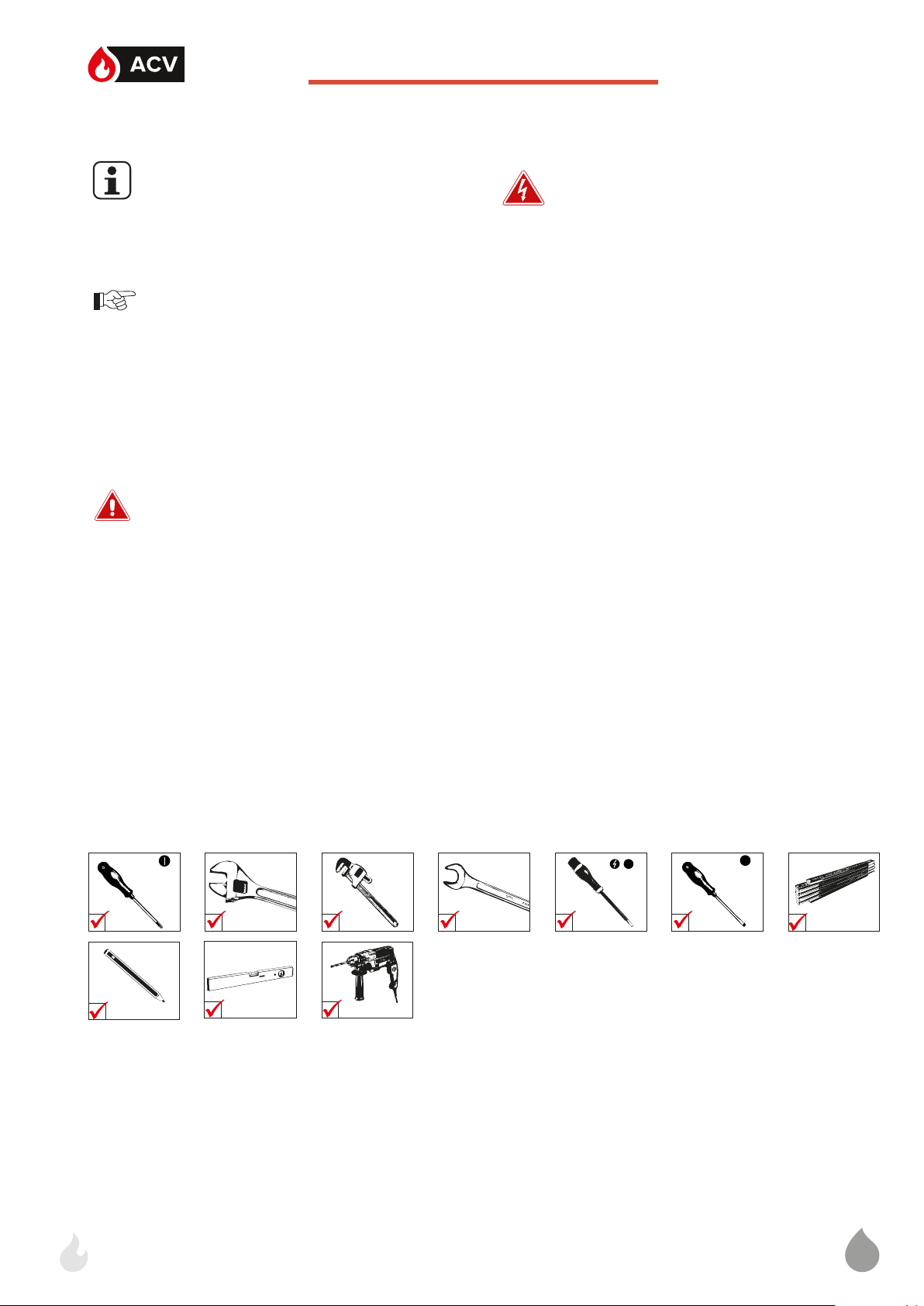
TOOLS REQUIRED FOR THE INSTALLATION
have been given instruction concerning the use
of the appliance by a person responsible for their
safety.
A1007841-664Y7800 • A
Page 13

13
EN
Installation
PACKAGE CONTENTS
The E-Tech W boilers are delivered assembled and
packaged.
At product reception and after removal of
packaging, check the package contents and
that the appliance is free of damages.
• One E-Tech W boiler
• Installation, Operation and Maintenance Instructions
• A wall mounting kit
HANDLING INSTRUCTIONS
• The weight of this boiler is 36Kg, which could
present a risk of injury. Ask for help to lift it or
handle it, or use an appropriate lifting means.
• Bring the appliance as close as possible to
the installation location before removing the
packaging.
BOILER INSTALLATION ON THE WALL
• The boiler must be mounted on a non
flammable support.
• Make sure to level the bracket at installation.
1. Observing the distances below, drill 2 holes of
14mm x 100mm.
2. Using the provided hardware, attach the bracket
to the wall, making sure the bracket is level.
3. Hang the boiler on the bracket.
48,4 mm
101,6 mm
101,6 mm
48,4 mm
REMOVING THE BOILER FROM THE
PACKAGING
Before lifting the boiler from the packaging,
ensure that the installation area is clear
and that there are no obstacles making the
installation difficult or unsafe.
1. Open the box and remove the cardboard packaging.
2. Remove the protection pieces and discard in accordance with applicable local regulations.
3. With help from another person, lift the boiler from
the packaging holding the lipped front edges of
the side panels.
Do not lift or carry the boiler using the
automatic air vent installed at the top and
the pump at the bottom.
A1007841-664Y7800 • A
Page 14
14
EN
Installation
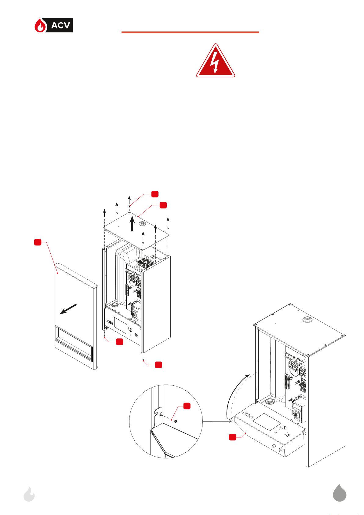
REMOVAL AND INSTALLATION OF THE
ACCESS PANELS
Set-up conditions
• Boiler shut down using the ON/OFF switch
• External power supply isolated (through the external electrical box)
• Boiler cooled down (if it was in operation)
Procedure
1. If the boiler was in operation or filled with water:
• Isolate the heating circuit through the isolating
valve.
• Drain the boiler. See "Draining the Boiler" on
page 24.
1
2
2. Remove the automatic air vent located at the top
of the boiler. Retain for reinstallation.
3. Release six screws (1). Retain for reinstallation.
4. Remove the front panel (3) and top cover (2).
5. To get access to the control panel wiring:
• Release two screws (4) from the bottom of the
control panel (5). Retain for reinstallation.
• Rotate the control panel 180° upwards.
• Block the control panel in position using one of
the two retained screws (4).
6. Perform the procedure in the reverse order for
panel reinstallation.
Follow-on tasks
• Restart the boiler as required, refer to "Starting
the boiler" on page 23.
3
4
4
4
5
A1007841-664Y7800 • A
Page 15

15
EN
Installation
RECOMMENDATIONS FOR THE HYDRAULIC INSTALLATION
• Thoroughly rinse the system before connecting the boiler
• Water treatment is recommended to prevent corrosion and the formation of scale in the boiler and piping.
• If the boiler is to be installed in an existing system, ACV recommends using a cleaning agent in the
systems.
• After connecting the hydraulic circuit, check the absence of leaks.
HEATING CONNECTION
Make sure to install isolating valves on the system heating circuit, so as to be able to drain the boiler,
without draining the whole system.
Typical system - high temperature
KEY
1. Isolation valve
2. Circulating pump (built-in)
3. Filling valve
4. Check valve
5. Expansion vessel (built-in, for a 160L circuit)
6. Safety valve (built-in)
7. Draining valve
8. Automatic air vent (built-in)
8
Typical system - low temperature
KEY
1. Isolation valve
2. 3-way mixing valve
3. Circulating pump (built-in)
4. Filling valve
5. Check valve
6. Expansion vessel (built-in, for a 160L circuit)
7. Safety valve (built-in)
8. Draining valve
9. Automatic air vent (built-in)
Cold water
Hot water
9
6
2
7
11
4
3
5
3
1
2
4
8
1
6
5
7
In the case of a floor heating system, make
sure that the pomp is set to the "Constant
pressure" mode.
A1007841-664Y7800 • A
Page 16

16
EN
Installation
PUMP SET-UP
• Depressing shortly the button allows to display
the current set-up (operation mode)
• Depressing the button for more than 2 sec. gives
access to the setting mode See table below for
the available operation modes.
• After 10 sec. without action, the “Performance”
mode is back.
Available Operation Modes
Constant curve:
The circulation pump works according to a constant
curve, which is the standard operation for a pump.
The pump will then run following the max curve
when demand is high, e.g. in the case of DHW priority, and according to the min curve when demand is
low (night mode).
LED 1 LED 2 LED 3 LED 4 LED 5
Proportional pressure Green
Constant pressure Green
Constant curve Green
Curve 1
Curve 2
Curve 3
Curve 4/Auto
£
¢
¢ ¢
¢
£ £
¢
By default, the pump is set to the
"Porportional Pressure" mode / Curve 3 (See
symbols in bold in the table).
Proportional pressure:
Default mode, applicable to most heating systems.
Pressure increases and decreases according to the
heat demands. Three preset curves are available,
from the lowest to the highest. The AutoAdapt curve
allows the pump to operate with the best eciency
for the type of system. This is the preferred mode for
two-pipe systems, with thermostatic valves and long
piping (high pressure drop).
Once the set-up is completed, the pump can
be locked to prevent any accidental change.
Press the button for more than 10 secondes
and all the LED will light (except the red one)
and blink for 1 second to indicate that the
lock is on. Proceed the same way to unlock.
Constant pressure:
Pressure is kept constant whether there is a heat demand or not. This is the typical mode for floor-heating systems or one-pipe systems with low pressure
drop.
A1007841-664Y7800 • A
Page 17

17
SAFETY INSTRUCTIONS FOR THE
EN
ELECTRICAL INSTALLATION
Installation
SIZING THE SUPPLY WIRES
• Electrical connections must be carried out
by a qualified technician, in accordance with
regulations applicable to electrical systems.
• Make sure that the boiler is connected to the
earth.
• As far as the power input to the boiler is
concerned, the installation must comply
with standard EN 60364-1 that define the
applicable levels of insulation, and with
all provisions applicable to installation
conditions.
• For protection against electrical hazard, it is
always recommended to install a differential
cut-out device (Ground Fault Isolator) on the
power supply circuit, upstream of the boiler.
• The control circuit is protected by a 3A
magnetic circuit breaker.
• The default electrical safeties integrated in
the boiler protect the internal parts of the
boiler.
• Any additional electrical safety device must
be installed outside the boiler.
• For protection against overheating, it is
advisable to place an external positive
safety power cut-out, controlled by the
boiler safety thermostat.
The supply wires are sized depending of the type
and current of the Magnetic Circuit Breaker (MCB),
the latter being sized according to the nominal current of the boiler.
The admissible current of the supply wires depends
on the ambient temperature, the section and length
of the wires, the wires insulation, the wires assembly,
the type of installation and the environment.
The following values are provided for information,
considering an ambient temperature of 30°C and a
maximal length of 5 meters. In all the cases, the installation must be performed in accordance with the
applicable Wiring Regulations.
Nominal section
(mm)
1.5 16
2.5 25
4 32
6 40
10 63
16 80
Nominal current of the
MCB (A)
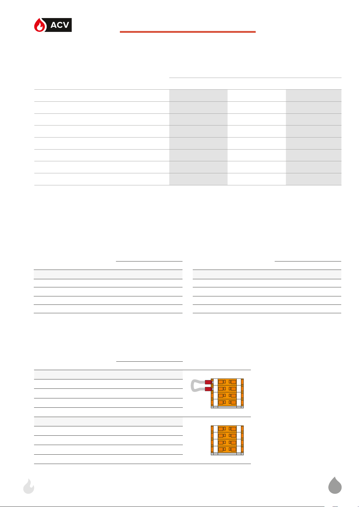
CONNECTING THE POWER SUPPLY
• This appliance must be permanently connected to fixed wiring and must be earthed.
• The wiring must be carried out by a competent person and in accordance with the current IEE Wiring
Regulations.
E-Tech W 09 - 15 Mono E-Tech W 09 - 15 - 22 - 28 Tri E-Tech W 36 Tri
T1 T2 T3 T4
T1 T2 T3 T4
L1PE L1
400 V ~ 50 Hz
N L2 L3 PE
230 V ~ 50 Hz
(3A)
PE L1
230 V ~ 50 Hz
(3A)
T1 T2 T3 T4
T1 T2 T3 T4
N NL1 PE
230 V ~ 50 Hz
N L2 L3 PE
230 V ~ 50 Hz
(3A)
T1 T2 T3
T1 T2 T3
L1PE L1
400 V ~ 50 Hz
A1007841-664Y7800 • A
Page 18

18
EN
Installation
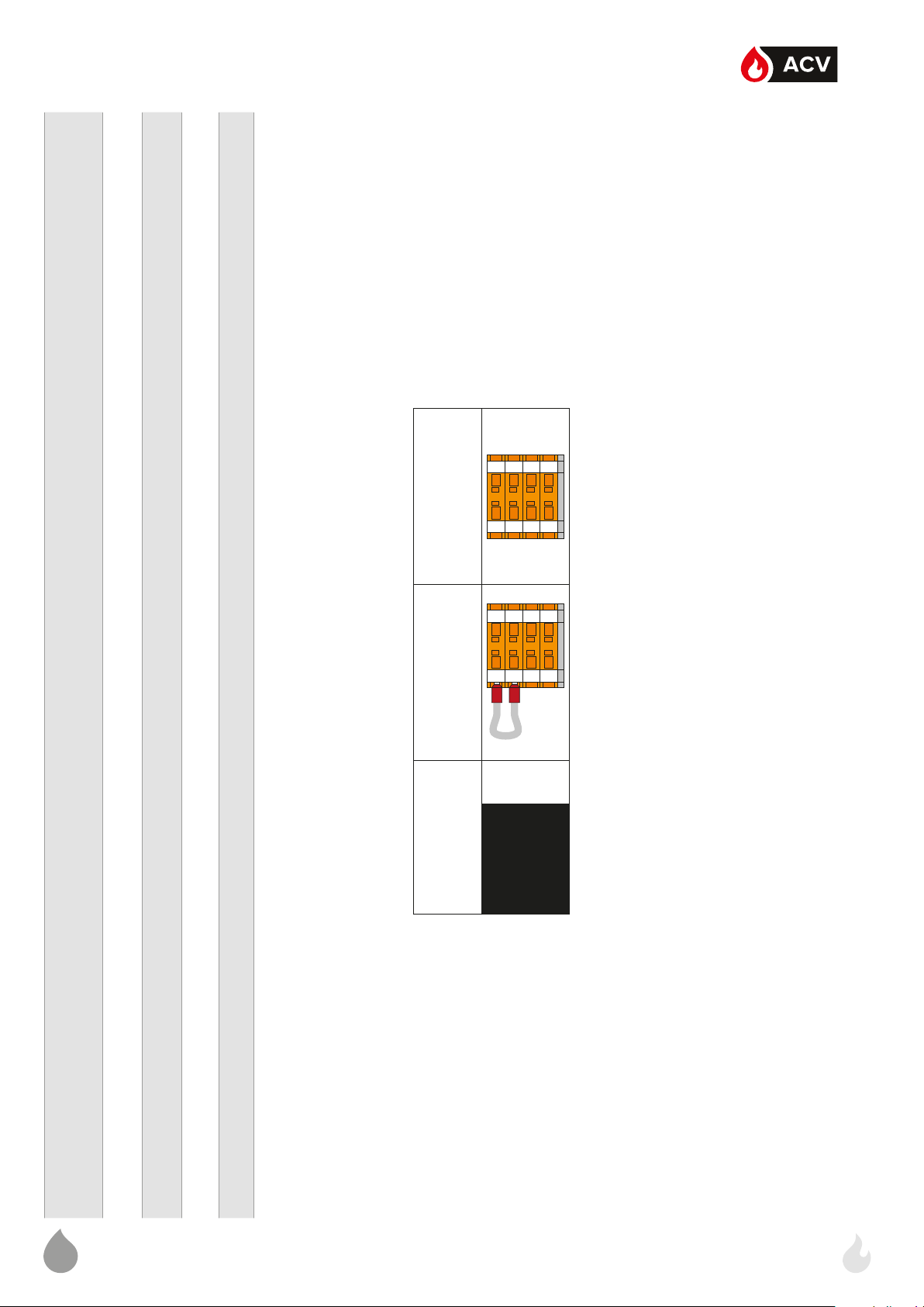
CONNECTING THE ELECTRICAL ACCESSORIES
Models : • E-Tech W 09 - 15 Mono
• E-Tech W 22 Tri
1-2 : Time clock or controller supply (optional)
3-4 : DHW kit (optional)
5-6 : Stop Bridge or time clock switch control (optional)
7-8 : Room thermostat (optional)
9-10-11 : Heating pump
12-13 : Relay K3 deactivated
1
2
3
4
5
6
7
8
9
10
11
12
13
14
15
1
2
3
4
5
6
7
8
9
10
11
12
13
14
15
TB1
Models : E-Tech W 09 - 15 Tri
1-2 : Time clock or controller supply (optional)
3-4 : DHW kit (optional)
5-6 : Stop Bridge or time clock switch control (optional)
7-8 : Room thermostat (optional)
9-10-11 : Heating pump
1
2
3
4
5
6
7
8
9
10
11
12
13
14
15
1
2
3
4
5
6
7
8
9
10
11
12
13
14
15
Models : E-Tech W 28 - 36 kW Tri
1-2 : Time clock or controller supply (optional)
3-4 : DHW kit (optional)
5-6 : Stop Bridge or time clock switch control (optional)
7-8 : Room thermostat (optional)
9-10-11 : Heating pump
12-13 : Relay K3 deactivated
14-15 : Relay K4 deactivated
1
2
3
4
5
6
7
8
9
10
11
12
13
14
15
1
2
3
4
5
6
7
8
9
10
11
12
13
14
15
TB1
TB1
A1007841-664Y7800 • A
Page 19

19
CONFIGURATIONS
39
38
37
36
35
34
33
32
31
29
28
27
26
25
24
23
22
21
19
40
20
18
17
16
15
14
13
12
11
9
30
10
8
7
6
5
4
3
2
1
39
38
37
36
35
34
33
32
31
29
28
27
26
25
24
23
22
21
19
40
20
18
17
16
15
14
13
12
11
9
30
10
8
7
6
5
4
3
2
1
39
38
37
36
35
34
33
32
31
29
28
27
26
25
24
23
22
21
19
40
20
18
17
16
15
14
13
12
11
9
30
10
8
7
6
5
4
3
2
1
39
38
37
36
35
34
33
32
31
29
28
27
26
25
24
23
22
21
19
40
20
18
17
16
15
14
13
12
11
9
30
10
8
7
6
5
4
3
2
1
EN
CH Connection
Installation
CH + DHW Connection: “Y” PLAN - See
page 20
Limiting the maximum temperature setpoint
Factory setting
0 - 87°C
Floor heating
0 - 50°C
Limiting the maximum temperature setpoint
60 - 87°C
1
1
2
2
3
3
4
4
5
5
6
6
7
7
8
8
9
9
10
10
11
11
12
12
13
13
14
14
15
15
CH + DHW Connection: “S” PLAN - See page 21
Limiting the maximum adjustable temperature
60 - 87°C
A1007841-664Y7800 • A
M M
Page 20

20
EN
Installation
HONEYWELL SUNDIAL WIRING DIAGRAM : Y PLAN
15
1133224455667788991010111112121313141415
Note: All bold numbers indicate a DIN rail terminal connection
V4073A
b
MID POSITION
w
bk- black
br- brown
r-red
w-white
y- yellow
o - orange
b - blue
v - violet
p - pink
CABLE COLOUR CODES
ZONE VALVE
o
gr - grey
Note: Illustrated model: 22 kW Tri
gr
CYLINDER
T6306B
ROOM STAT
b
STAT
2C
1
w
3
1
2
b
7 8 9 10
E
1 432 5 6
N L
HTG
HW ON
HW OFF
Honeywell
Sundial Wiring Centre
`Y ` Plan
Note: Earth wires not shown for clarity
During installation the earth wires from each
component connect to terminal 3 in the wiring centre
A1007841-664Y7800 • A
Page 21

21
EN
Installation
HONEYWELL SUNDIAL WIRING DIAGRAM : S PLAN
15
1133224455667788991010111112121313141415
Note: All bold numbers indicate a DIN rail terminal connection
o
gr
MOTOR
b
brbr
gr
MOTOR
b
V4043H
DHW ZONE VALVE
o
CYLINDER
STAT
3
1
2
T6306B
V4043H
HTG ZONE VALVE
ROOM STAT
b
o
o
br
C
b
gr
gr
7 8 9 10
br
b
1 432 5 6
bk- black
CABLE COLOUR CODES
E
HTGHW
br- brown
r-red
w-white
y- yellow
o - orange
b - blue
v - violet
p - pink
gr - grey
Note: Illustrated model: 22 kW Tri
N L
Honeywell
Sundial Wiring Centre
`S ` Plan
Note: Earth wires not shown for clarity
During installation the earth wires from each
component connect to terminal 3 in the wiring centre
A1007841-664Y7800 • A
Page 22

22
EN
C
CHECKS AND SETUP BEFORE START UP
Set-up conditions
• External power supply isolated
Procedure
1. Remove the boiler front panel, refer to "Removal and In-
stallation of the Access Panels" on page 14.
2. Set the internal MCB to OFF (See ML book).
3. Check all electrical connections for tightness.
4. Ensure all internal relays, contactors, etc. are secure on the
DIN rails.
5. Set all the control panel control switches to OFF.
6. Check the power stage delay timer settings:
• Adjustment screw (A) is factory set to the “1 to 10 min.”
position which is the optimum setting for the boiler. The
timer can be adjusted from 0.1 sec. to 10 hours.
• Adjustment screw (B) is used to set the DELAY ON time
of the following stage contactors, the available settings
are in 1 minute increments if A is set to 1 to 10 minutes.
• This function is particularly useful in areas where gradu-
al switching of electrical load is required and the resulting maximum demand kept to a minimum. The timers
add to the flexibility of the installation but must be optimised by a qualified engineer. The nominal setting is “1”.
7. Set the control thermostat to the desired temperature.
FILLING THE SYSTEM
If the system is fitted with an external
hot water tank, first put the DHW circuit
under pressure before pressurizing the
heating (primary) circuit. Refer to the hot
water preparation tank manual for more
information.
Set-up conditions
• External power supply isolated
• DHW circuit (if any) under pressure
Filling procedure
1. Open the isolating valves (1).
2. Make sure that the drain valve (2) is tightly closed.
3. Open the filling valve (3).
4. Make sure the air vent is open, as required.
5. Once the system is bled from air, bring the pressure to the
static pressure between 1.5 bar and 2 bar.
6. Close the filling valve (3)
Follow-on tasks
• Check there is no leak.
A
2
1
B
1
3
Cold water
Hot water
A1007841-664Y7800 • A
Page 23

23
STARTING THE BOILER
EN
Set-up conditions
• Hydraulic and electric connections made
• External power supply isolated
• Boiler filled and pressurised
Procedure
Before starting the boiler, make sure that the
air is bled from the heating circuit using the
automatic air vent located at the top of the
boiler. Note that the black dust cap on the
air vent should be left loose to allow the auto
vent to function.
Commissioning
11. The boiler temperature will now rise as indicated by the
combined temperature and pressure gauge (3).
12. The temperature will continue to rise until the control thermostat temperature setting is reached then the boiler will switch
o.
13. Set timeclock (if fitted) and/or external controls to desired
boiler operating on/o times.
Follow-on Task(s)
1. Remove the red sticker from the front face of the boiler.
After several days of operation, re-check all
electrical and hydraulic connections for tightness,
as well as the system operating pressure. Correct
and adjust as necessary.
3
4
1 2
1. Place all the switches (1 & 2) of the control panel to OFF.
2. Set the internal MCB to ON (See ML book).
3. Install the boiler front panel, refer to "Removal and In-
stallation of the Access Panels" on page 14.
4. Provide power supply to boiler through the external electrical box.
5. Turn the boiler on using the ON/OFF switch (1).
6. After a few minutes of operation of the circulating pump,
check the circuit pressure on the boiler manometer (3).
7. If necessary, place the ON/OFF switch (1) to OFF, bleed
the air from the circuit and top-up the circuit with water to
reach the minimum pressure of 1 bar, then turn the boiler
ON again.
8. If necessary, perform any additional set-up of the pump, according to the type of system. Refer to "Pump Set-up" on
page 16.
9. Switch on the power levels switch stage 1, the first stage
contactors will energise.
10. Switch on the power levels switch stage 2, after a short
delay the second stage contactors will energise.
A1007841-664Y7800 • A
Page 24

24
EN
M
RECOMMENDATIONS FOR THE BOILER
MAINTENANCE
Essential recommendations for the electrical
safety
• Before opening the boiler for maintenance,
turn off the boiler by pushing on the ON/OFF
master switch.
• Isolate the external power supply of the
appliance before performing any operation,
unless it is required to take measurements or
perform system setup.
Essential recommendations for safety
• Water flowing out of the drain valve may be
extremely hot and could cause severe scalding.
• Do not use solvents to clean any of the
components. The components could be
damaged, resulting in unreliable or unsafe
operation.
Essential recommendations for the correct
operation of the appliance
• It is recommended to have the boiler serviced
at least once a year or every 1,500 hours by a
qualified technician, preferably at the start of
the heating season. More frequent servicing
may be required depending on boiler use.
Please consult your installer for advice.
• The boiler maintenance will be carried out by
a qualified engineer, and the defective parts
may only be replaced by genuine factory
parts.
• Make sure to replace any gaskets or seals on
the removed components before reinstalling
them.
• To ensure maximum efficiency and reliability
of the unit, it is recommended that the enduser perform the periodic checks mentioned
in the Safety section of this manual.
• Control the tightness of the hydraulic circuit
connections.
BOILER SHUT-DOWN FOR
MAINTENANCE
1. Switch the boiler o using the ON/OFF master switch
2. Isolate the external power supply.
DRAINING THE BOILER
Set-up conditions
• Boiler shut down through the ON/OFF switch
• External power supply isolated (through the external elec-
trical box)
• Boiler cooled down (if it was in operation)
Procedure
1. Close the heating circuit isolating valves (1)
2. Open the draining valve (2) and allow the water to flow to
the drain
3. Actuate the automatic air vent (3).
Follow-on Task(s)
None
3
2
1
1
Cold water
Hot water
A1007841-664Y7800 • A
Page 25

25
EN
Maintenance
Before carrying out any work on the system ensure that the boiler is cool and all electrical supplies
are isolated.
BOILER MAINTENANCE
Set-up conditions
• Boiler shut down through the ON/OFF switch
• External power supply isolated (through the external elec-
trical box)
• Boiler cooled down (if it was in operation)
Procedure
1. Remove the top panel and front face of the boiler. Refer to
"Removal and Installation of the Access Panels" on
page 14.
2. Perform a visual inspection of the boiler looking out for
signs of water leakage from joints, expansion vessel, and
the area around the elements on top of the boiler.
3. Perform a visual inspection of all wiring and cables in the
boiler casing, checking for signs of overheating or burning.
4. Check all push-on electrical connectors for tightness and
good connection to the relative components.
5. Using an appropriate screwdriver, check all electrical terminals on DIN rails and on all components for tightness.
6. Check the settings on the internal timers in accordance with
"Checks and setup before start up" on page 22.
Follow-on task(s)
7. Replace the heating elements if necessary. See "Replac-
ing the Heating Elements" on page 26.
8. Restart the boiler, refer to "Starting the boiler" on page
23.
RESETTING THE HIGH LIMIT SAFETY
THE RMOSTAT
Set-up conditions
• Boiler shut down through the ON/OFF switch
• External power supply isolated (through the external electri-
cal box)
• Boiler cooled down (if it was in operation)
Procedure
1. Unscrew and remove the safety thermostat (1) cover, at the
bottom of the boiler.
2. Push on the safety thermostat (1) to reset it. A “click” sound
should be heard.
In case no “click” sound is heard, the safety
device is not the cause of the shut-off.
Troubleshooting should be performed by a
qualified service engineer.
3. Reinstall the safety thermostat cover.
Follow-on task(s)
1. Activate electrical power through the external electrical box
2. Turn the boiler on using the ON/OFF switch.
3. Make sure that the indicator light (2) is o.
CHECKING THE SAFETY DEVICES
9. Check the correct operation of:
• the thermostats.
• the safety valve(s).
• the automatic air vent.
2 1
A1007841-664Y7800 • A
Page 26
26
EN
Maintenance
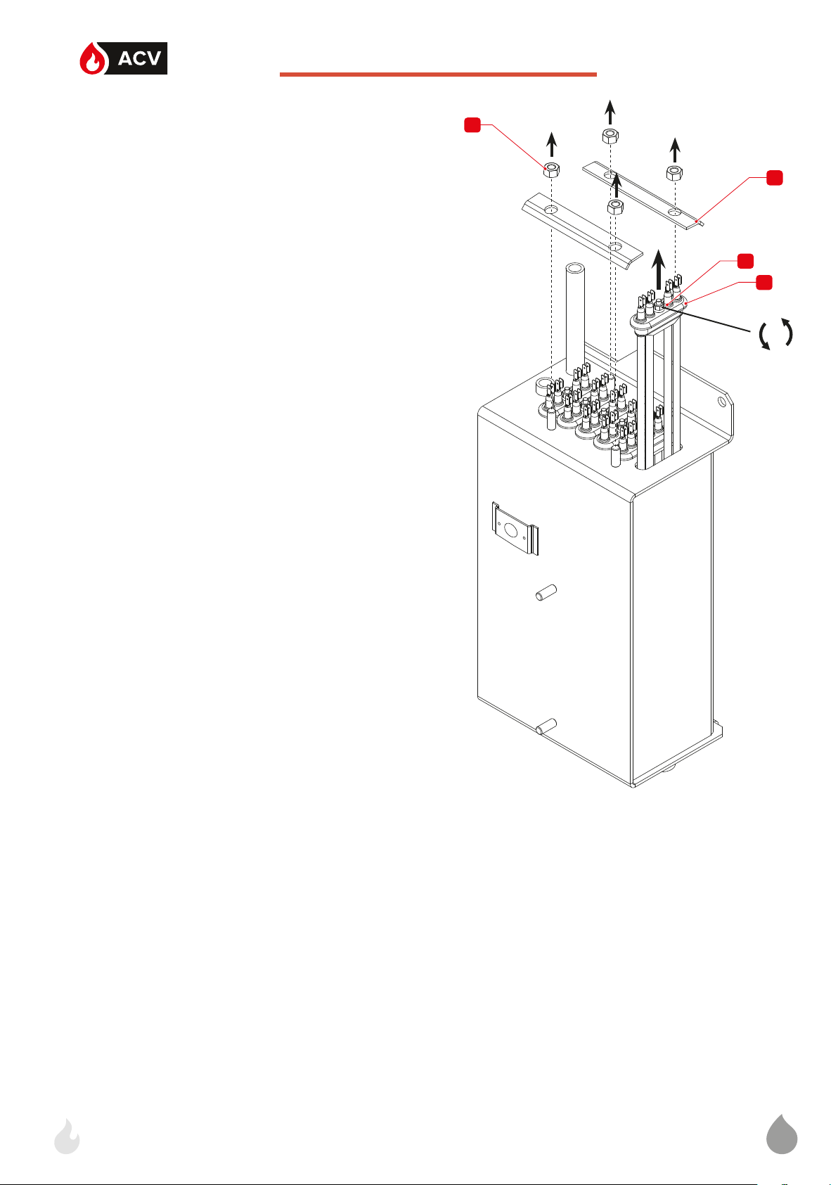
REPLACING THE HEATING ELEMENTS
Set-up conditions
• Boiler shut down through the ON/OFF switch
• External power supply isolated (through the external elec-
trical box)
• Boiler cooled down (if it was in operation)
• Top cover removed (see "Removal and Installation of
the Access Panels" on page 14).
Removal Procedure
1. Release four nuts (1). Retain for reinstallation.
2. Remove two holders (2). Retain for reinstallation.
3. Release the center nut (3) of the heating element (4) to be
removed.
4. Remove heating element (4). Clean or discard it as required.
Installation Procedure
1. Install the clean/new heating element (4) in position. Do not
tighten the center nut (3) at this stage.
2. Install two holders (2) and tighten with two retained nuts (1).
3. Tighten the center nut (3) of the heating element (4).
1
2
3
3
4
Follow-on Task(s)
1. Check that all nuts are tight.
2. Reinstall the top cover. Refer to "Removal and Installa-
tion of the Access Panels" on page 14.
3. Restart the boiler as required, refer to "Starting the boil-
er" on page 23.
A1007841-664Y7800 • A
Page 27

27
TROUBLESHOOTING THE PUMP
EN
ALARM STATUS
T
Blocking
Voltage too low
Electrical failure
Pump rotor blocked; wait for the pump to restart or mechanically unblock the shaft with a screwdriver.
Supply voltage too low; check the supply voltage.
The pump has stopped because of a lack of voltage supply
or a serious failure; check the supply voltage or replace the
pump, as required.
A1007841-664Y7800 • A
Page 28

ACV International
Oude Vijverweg, 6
B-1653 Dworp
Belgium
belgium.service@acv.com
www.acv.com
Page 29

E-Tech W
ML
09 - 15 Mono
09 - 15 - 22 - 28 - 36 Tri
A1007841_664Y7800 • A
Page 30

2
...................................................................3
ML
..................................................................4
E-Tech W 09 Mono .................................................................. 4
E-Tech W 15 Mono ................................................................... 8
E-Tech W 09 - 15 Tri ...............................................................12
E-Tech W 22 Tri .......................................................................16
E-Tech W 28 Tri ..................................................................... 20
E-Tech W 36 Tri ......................................................................24
.................................................................. 28
MONO
TRI
Dimensions - Afstanden - Dimensiones - Dimensioni - Abmessungen - Wymiary Габаритные размеры
Wiring diagrams - Schémas électriques - Elektrische schema's - Diagramas de cableado
- schema elettrico - schematy połączeń - схемы подключения
Information - Informatie - Informaciones - Informazioni - Informationen - Informacje Информация
Single phase - monophasé - Eenfasig - Monofasico - Monofase - Wechselstrom - Jednofazowe - однофазный ток
Three phase - Triphasé - Driefasig - Trifasico - Trifase - Drehstrom - Trójfazowy трехфазный ток
Page 31

3
763 mm
442 mm
332 mm
185 mm
370 mm
105 mm
ML
Min.
25 mm
Min.
400 mm
Min.
200 mm
Page 32

4
E-TECH W 09 MONO
ML
Control - Commande - Besturing - Mando - Comando - Kontrol - regulacja - регулирование
1
Br
3
OrOrR
1
B
B
K4
Or Or
9
S5
W
A1
A2
1.1
1.2
T1
2.2
B
Or
R
M
Pk
12
13
B
B
B Br G
11 10 4 2
B
B
B
B
W W
5
P
Br
P
Bk
2 1
t
S2
PS
P
OrYOr Y
2 1
6
7
7
P
8
Y
1
t
C
GG Or
S3
2 1
t
B
Or Or
B
B
S4
1.1
1.2
2.2
B
B
S1
1.2 2.2
1.1 2.1
Bk Bk
Br
Br
R
R RR
4
B
CB
Br
2
K1 K3 K2
B
B
DS1
B
B
PE
3
B
1 2
Br
1
- Blu - Blau -Niebieski -
Голубой
Negro - Nero - Schwarz
- Czarny - Черный
Marrón - Marrone - Braun
- Brązowy - Коричневый
- Grigio - Grau - Siwy -
Серый
Naranja - Arancione
- Pomarańczowy -
B : Blue - Bleu - Blauw - Azul
Bk : Black - Noir - Zwart -
Br : Brown - Brun - Bruin -
G : Grey - Gris - Grijs - Gris
Or : Orange - Oranje -
- Różowy - Розовый
- Rojo - Rosso - Rot -
Czerwony - Красный
Blanco - Bianco - Weiß -
Biały - Белый
Amarillo - Gallo - Gelb -
Оранжевый
Pk : Pink - Rose - Roze - Rosa
R : Red - Rouge - Rood
W : White - Blanc - Wit -
Żółty - Желтый
Y : Yellow - Jaune - Geel -
Page 33

5
étage + lampe - Vermogenschakelaar 2 + lampje - Interruptor del segundo nivel + luz - Interruttore luminoso
ML
étage + lampe - Vermogenschakelaar 1 + lampje - Interruptor del primer nivel + luz - Interruttore luminoso del
er
obwodu regulacji - Цепь управления
Leuchte - ON/OFF zał/wyłącznik + lampa - Переключатель ВКЛ/ВЫКЛ + лампы
mostato de seguridad de rearme manual [103°C] - Termostato di sicurezza a riarmo manuale [103°C] - Manuell entriegelbares Sicherheitsthermostat [103°C] - Termostat
CB Circuit breaker - Disjoncteur - Magnetothermische Schakelaar - Disyuntor magnetotérmico - Interruttore magnetotermico generale ON/OFF - Sicherung - Bezpiecznik
S2 Manual reset safety thermostat [103°C] - Thermostat de sécurité à réarmement manuel [103°C] - Veiligheidsthermostaat met handmatige herinschakeling [103°C] - Ter-
S1 ON/OFF switch + lamp - Interrupteur ON/OFF + lampe - ON/OFF- schakelaar + lampje - Interruptor ON/OFF + luz - Interruttore luminoso ON/OFF - ON/OFF-Schalter +
stato di sicurezza mancanza acqua - Wassermangelsicherung - Czujnik ciśnienia wody - Реле минимального давления
bezpieczeństwa z ręcznym odblokowaniem [103°C] - Защитный термостат с ручным перезапуском [103°C]
PS Low-water pressure switch - Pressostat de sécurité manque d’eau - Veiligheidsdrukschakelaar watergebrek - Presostato de seguridad en caso de falta de agua - Presso-
вочный термостат
primo livello di potenza - Stufenschalter 1 + Leuchte - Przełącznik poziomu mocy 1 + lampa - Переключатель уровня мощности - ступень1 + лампы
kaźnik mocy 1 - poziom 1 - Силовое реле 1 - ступень 1
Przekaźnik mocy 2 - poziom 1 - Силовое реле 2 - ступень 1
DS1 Alarm - Signal de mise en sécurité - Alarm - Alarma - Allarme - Alarm - Alarm - Сигнализация
S3 Control thermostat - Thermostat de commande - Regelthermostaat - Termostato de mando - Termostato di comando - Einstellthermostat - Termostat kotłowy - Регулиро-
S4 Power switch level 1 + lamp - Commutateur de puissance 1
K1 Power relay 1 - level 1 - Relais de puissance 1 - étage 1 - Vermogensrelais 1 - trap 1 - Relé de potencia 1 - nivel 1 - Relè di potenza 1 - livello 1 - Leistung Relais 1 - Stufe 1 - Prze-
K3 Power relay 2 - level 1 - Relais de puissance 2 - étage 1 - Vermogensrelais 2 - trap 1 - Relé de potencia 2 - nivel 1 - Relè di potenza 2 - livello 1 - Leistung Relais 2 - Stufe 1 -
éme
электромагнитное реле
externeregeling (optioneel) - Alimentación eléctrica para optimizador o regulador (opcional) - Alimentazione elettrica per un regolatore o per un orologio per programmazione
giornaliera (in opzione) - Strom Versorgung für Schaltuhr oder Regler (Optional) - Zasilanie z zegara czasowego (opcja) - Перемычка или таймер часов работы (опция)
ГВС комплект (опция)
neel) - Puente de parada general o interruptor del optimizador (opcional) - Ponte di arresto generale o comando di un orologio per programmazione giornaliera
del secondo livello di potenza - Stufenschalter 2 + Leuchte - Przełącznik poziomu mocy 2 + lampa - Переключатель уровня мощности - ступень2 + лампы
Przekaźnik mocy 1 - poziom 2 - Силовое реле 1 - ступень 2
T1 Timer - Temporisateur - Timer - Temporizador - Temporizzatore - Zeitschalter - Przekaźnik czasowy - Реле времени включения второй ступени
S5 Power switch level 2 + lamp - Commutateur de puissance 2
K2 Power relay 1 - level 2 - Relais de puissance 1 - étage 2 - Vermogensrelais 1 - trap 2 - Relé de potencia 1 - nivel 2 - Relè di potenza 1 - livello 2 - Leistung Relais 1 - Stufe 2 -
K4 Safety switch - Contacteur de sécurité - Veiligheidscontact - Contactor de seguridad - Contattore di sicurezza - Sicherheitsrelais - Przekaźnik główny - Отключающее
1-2 Time clock or controller supply (optional) - Alimentation électrique pour un régulateur ou un programmateur journalier optionnel - Voedingsspanning voor Schakelklok of
3-4 DHW kit (optional) - Kit sanitaire (en option) - Sanitaire kit (optioneel) - Kit sanitario (opcional) - Kit sanitario (opzionale) - Sanitärer Satz (Optional) - Zestaw CWU (opcja) -
(in opzione) - Schaltuhr oder Regler Eingang (Optional) - Mostek wyłączający lub wyłącznik czasowy (opcja) - Перемычка или таймер часов работы (опция)
le) - Raumthermostat (Optional) - Termostat pokojowy (opcja) - Комнатный термостат (опция)
5-6 Stop Bridge or time clock switch control (optional) - Pont d’arrêt général ou commande du programmateur journalier optionnel - Aansluiting Schakelklok of regeling (optio-
7-8 Room thermostat (optional) - Thermostat d’ambiance (en option) - Omgevingsthermostaat (optioneel) - Termostato de ambiente (opcional) - Termostato ambiente (opziona-
9-10-11 Heating pump - Pompe chauffage - Warmtepomp - Circulador de calefacción - Circolatore di riscaldamento - Heizpumpe - Pompa kotła - Насос котла
Перемычка ограничения мощности
12-13 Relay K3 deactivated - Relais K3 désactivé - Desactivering van relais K3 - Descarga del relé K3 - Esclusione del relè K3 - Abschaltung Relais K3 - Mostek przekaźnika K3 -
Page 34

6
E-TECH W 09 MONO
ML
Power - Puissance - Vermogen - Potencia - Potenza - Leistung - Zasilania - Силовая часть
BB
R
B
Br
BB
Br
B
Bk
BB
Bk
R
B
Br
Br
B
Bk
Bk
B
B
R
R
K1 K2 K3
B : Blue - Bleu - Blauw - Azul - Blu - Blau -Niebieski - Голубой
Bk : Black - Noir - Zwart - Negro - Nero - Schwarz - Czarny - Черный
Br : Brown - Brun - Bruin - Marrón - Marrone - Braun - Brązowy - Коричневый
G : Grey - Gris - Grijs - Gris - Grigio - Grau - Siwy - Серый
Or : Orange - Oranje - Naranja - Arancione - Pomarańczowy - Оранжевый
Pk : Pink - Rose - Roze - Rosa - Różowy - Розовый
R : Red - Rouge - Rood - Rojo - Rosso - Rot - Czerwony - Красный
W : White - Blanc - Wit - Blanco - Bianco - Weiß - Biał y - Белый
Y : Yellow - Jaune - Geel - Amarillo - Gallo - Gelb - Żółty - Желтый
PE
B
B
B
R
Bk
Br
B
B
B
R
Bk
Br
L N
K4
Page 35

7
12121313141415
15
12121313141415
15
ML
Силовое реле 1 - ступень 1
K1 Power relay 1 - level 1 - Relais de puissance 1 - étage 1 - Vermogensrelais 1 - trap 1 - Relé de potencia 1 - nivel 1 - Relè di potenza 1 - livello 1 - Leistung Relais 1 - Stufe 1 - Przekaźnik mocy 1 - poziom 1 -
K2 Power relay 1 - level 2 - Relais de puissance 1 - étage 2 - Vermogensrelais 1 - trap 2 - Relé de potencia 1 - nivel 2 - Relè di potenza 1 - livello 2 - Leistung Relais 1 - Stufe 2 - Przekaźnik mocy 1 - poziom
2 - Силовое реле 1 - ступень 2
K3 Power relay 2 - level 1 - Relais de puissance 2 - étage 1 - Vermogensrelais 2 - trap 1 - Relé de potencia 2 - nivel 1 - Relè di potenza 2 - livello 1 - Leistung Relais 2 - Stufe 1 - Przekaźnik mocy 2 - poziom
1 - Силовое реле 2 - ступень 1
K4 Safety switch - Contacteur de sécurité - Veiligheidscontact - Contactor de seguridad - Contattore di sicurezza - Sicherheitsrelais - Przekaźnik główny - Отключающее электромагнитное реле
E-Tech W 09 8.4 kW 5.6 kW
Mono TB1
Page 36

8
E-TECH W 15 MONO
ML
Control - Commande - Besturing - Mando - Comando - Kontrol - regulacja - регулирование
1
Br
3
OrOrR
1
B
B
K4
Or Or
9
S5
W
A1
A2
1.1
1.2
T1
2.2
B
Or
R
M
Pk
12
13
B
B
B Br G
11 10 4 2
B
B
B
B
W W
5
P
Br
P
Bk
2 1
t
S2
PS
P
OrYOr Y
2 1
6
7
7
P
8
Y
1
t
C
GG Or
S3
2 1
t
B
Or Or
B
B
S4
1.1
1.2
2.2
B
B
S1
1.2 2.2
1.1 2.1
Bk Bk
Br
Br
R
R RR
4
B
CB
Br
2
K1 K3 K2
B
B
DS1
B
B
PE
3
B
1 2
Br
1
- Blu - Blau -Niebieski -
Голубой
Negro - Nero - Schwarz
- Czarny - Черный
Marrón - Marrone - Braun
- Brązowy - Коричневый
- Grigio - Grau - Siwy -
Серый
Naranja - Arancione
- Pomarańczowy -
B : Blue - Bleu - Blauw - Azul
Bk : Black - Noir - Zwart -
Br : Brown - Brun - Bruin -
G : Grey - Gris - Grijs - Gris
Or : Orange - Oranje -
- Różowy - Розовый
- Rojo - Rosso - Rot -
Czerwony - Красный
Blanco - Bianco - Weiß -
Biały - Белый
Amarillo - Gallo - Gelb -
Оранжевый
Pk : Pink - Rose - Roze - Rosa
R : Red - Rouge - Rood
W : White - Blanc - Wit -
Żółty - Желтый
Y : Yellow - Jaune - Geel -
Page 37

9
étage + lampe - Vermogenschakelaar 2 + lampje - Interruptor del segundo nivel + luz - Interruttore luminoso
ML
étage + lampe - Vermogenschakelaar 1 + lampje - Interruptor del primer nivel + luz - Interruttore luminoso del
er
obwodu regulacji - Цепь управления
Leuchte - ON/OFF zał/wyłącznik + lampa - Переключатель ВКЛ/ВЫКЛ + лампы
mostato de seguridad de rearme manual [103°C] - Termostato di sicurezza a riarmo manuale [103°C] - Manuell entriegelbares Sicherheitsthermostat [103°C] - Termostat
CB Circuit breaker - Disjoncteur - Magnetothermische Schakelaar - Disyuntor magnetotérmico - Interruttore magnetotermico generale ON/OFF - Sicherung - Bezpiecznik
S2 Manual reset safety thermostat [103°C] - Thermostat de sécurité à réarmement manuel [103°C] - Veiligheidsthermostaat met handmatige herinschakeling [103°C] - Ter-
S1 ON/OFF switch + lamp - Interrupteur ON/OFF + lampe - ON/OFF- schakelaar + lampje - Interruptor ON/OFF + luz - Interruttore luminoso ON/OFF - ON/OFF-Schalter +
stato di sicurezza mancanza acqua - Wassermangelsicherung - Czujnik ciśnienia wody - Реле минимального давления
bezpieczeństwa z ręcznym odblokowaniem [103°C] - Защитный термостат с ручным перезапуском [103°C]
PS Low-water pressure switch - Pressostat de sécurité manque d’eau - Veiligheidsdrukschakelaar watergebrek - Presostato de seguridad en caso de falta de agua - Presso-
вочный термостат
primo livello di potenza - Stufenschalter 1 + Leuchte - Przełącznik poziomu mocy 1 + lampa - Переключатель уровня мощности - ступень1 + лампы
kaźnik mocy 1 - poziom 1 - Силовое реле 1 - ступень 1
Przekaźnik mocy 2 - poziom 1 - Силовое реле 2 - ступень 1
DS1 Alarm - Signal de mise en sécurité - Alarm - Alarma - Allarme - Alarm - Alarm - Сигнализация
S3 Control thermostat - Thermostat de commande - Regelthermostaat - Termostato de mando - Termostato di comando - Einstellthermostat - Termostat kotłowy - Регулиро-
S4 Power switch level 1 + lamp - Commutateur de puissance 1
K1 Power relay 1 - level 1 - Relais de puissance 1 - étage 1 - Vermogensrelais 1 - trap 1 - Relé de potencia 1 - nivel 1 - Relè di potenza 1 - livello 1 - Leistung Relais 1 - Stufe 1 - Prze-
K3 Power relay 2 - level 1 - Relais de puissance 2 - étage 1 - Vermogensrelais 2 - trap 1 - Relé de potencia 2 - nivel 1 - Relè di potenza 2 - livello 1 - Leistung Relais 2 - Stufe 1 -
éme
электромагнитное реле
externeregeling (optioneel) - Alimentación eléctrica para optimizador o regulador (opcional) - Alimentazione elettrica per un regolatore o per un orologio per programmazione
giornaliera (in opzione) - Strom Versorgung für Schaltuhr oder Regler (Optional) - Zasilanie z zegara czasowego (opcja) - Перемычка или таймер часов работы (опция)
ГВС комплект (опция)
neel) - Puente de parada general o interruptor del optimizador (opcional) - Ponte di arresto generale o comando di un orologio per programmazione giornaliera
del secondo livello di potenza - Stufenschalter 2 + Leuchte - Przełącznik poziomu mocy 2 + lampa - Переключатель уровня мощности - ступень2 + лампы
Przekaźnik mocy 1 - poziom 2 - Силовое реле 1 - ступень 2
T1 Timer - Temporisateur - Timer - Temporizador - Temporizzatore - Zeitschalter - Przekaźnik czasowy - Реле времени включения второй ступени
S5 Power switch level 2 + lamp - Commutateur de puissance 2
K2 Power relay 1 - level 2 - Relais de puissance 1 - étage 2 - Vermogensrelais 1 - trap 2 - Relé de potencia 1 - nivel 2 - Relè di potenza 1 - livello 2 - Leistung Relais 1 - Stufe 2 -
K4 Safety switch - Contacteur de sécurité - Veiligheidscontact - Contactor de seguridad - Contattore di sicurezza - Sicherheitsrelais - Przekaźnik główny - Отключающее
1-2 Time clock or controller supply (optional) - Alimentation électrique pour un régulateur ou un programmateur journalier optionnel - Voedingsspanning voor Schakelklok of
3-4 DHW kit (optional) - Kit sanitaire (en option) - Sanitaire kit (optioneel) - Kit sanitario (opcional) - Kit sanitario (opzionale) - Sanitärer Satz (Optional) - Zestaw CWU (opcja) -
(in opzione) - Schaltuhr oder Regler Eingang (Optional) - Mostek wyłączający lub wyłącznik czasowy (opcja) - Перемычка или таймер часов работы (опция)
le) - Raumthermostat (Optional) - Termostat pokojowy (opcja) - Комнатный термостат (опция)
5-6 Stop Bridge or time clock switch control (optional) - Pont d’arrêt général ou commande du programmateur journalier optionnel - Aansluiting Schakelklok of regeling (optio-
7-8 Room thermostat (optional) - Thermostat d’ambiance (en option) - Omgevingsthermostaat (optioneel) - Termostato de ambiente (opcional) - Termostato ambiente (opziona-
9-10-11 Heating pump - Pompe chauffage - Warmtepomp - Circulador de calefacción - Circolatore di riscaldamento - Heizpumpe - Pompa kotła - Насос котла
Перемычка ограничения мощности
12-13 Relay K3 deactivated - Relais K3 désactivé - Desactivering van relais K3 - Descarga del relé K3 - Esclusione del relè K3 - Abschaltung Relais K3 - Mostek przekaźnika K3 -
Page 38

10
E-TECH W 15 MONO
ML
Power - Puissance - Vermogen - Potencia - Potenza - Leistung - Zasilania - Силовая часть
BB
R
B
Or
BB
Or
B
Bk
BB
Bk
R
B
Or
Or
B
Bk
Bk
B
R
B
R
B : Blue - Bleu - Blauw - Azul - Blu - Blau -Niebieski - Голубой
Bk : Black - Noir - Zwart - Negro - Nero - Schwarz - Czarny - Черный
Br : Brown - Brun - Bruin - Marrón - Marrone - Braun - Brązowy - Коричневый
G : Grey - Gris - Grijs - Gris - Grigio - Grau - Siwy - Серый
Or : Orange - Oranje - Naranja - Arancione - Pomarańczowy - Оранжевый
Pk : Pink - Rose - Roze - Rosa - Różowy - Розовый
R : Red - Rouge - Rood - Rojo - Rosso - Rot - Czerwony - Красный
W : White - Blanc - Wit - Blanco - Bianco - Weiß - Biał y - Белый
Y : Yellow - Jaune - Geel - Amarillo - Gallo - Gelb - Żółty - Желтый
K1 K2 K3
PE
B
B
B
B
B
B
R
R
Bk
Bk
Or
Or
2
2
2
2
2
2
1
B
1
B
1
B
1
R
1
Bk
1
Or
L N
S6
(F25A)
K4
Page 39
11
E-Tech W 15 14.4 kW 9.6 kW
12121313141415
15
12121313141415
15
ML
Mono TB1
di 25A - Leistungsklemmen mit Sicherung 25A - Zaciski zasilania z zabezpieczeniem 25A - Клеммная колодка силовой цепи с предохранителями 25A
Power relay 1 - level 1 - Relais de puissance 1 - étage 1 - Vermogensrelais 1 - trap 1 - Relé de potencia 1 - nivel 1 - Relè di potenza 1 - livello 1 - Leistung Relais 1 - Stufe 1 - Przekaźnik mocy 1 - poziom 1 -
Силовое реле 1 - ступень 1
Power relay 1 - level 2 - Relais de puissance 1 - étage 2 - Vermogensrelais 1 - trap 2 - Relé de potencia 1 - nivel 2 - Relè di potenza 1 - livello 2 - Leistung Relais 1 - Stufe 2 - Przekaźnik mocy 1 - poziom
2 - Силовое реле 1 - ступень 2
Power relay 2 - level 1 - Relais de puissance 2 - étage 1 - Vermogensrelais 2 - trap 1 - Relé de potencia 2 - nivel 1 - Relè di potenza 2 - livello 1 - Leistung Relais 2 - Stufe 1 - Przekaźnik mocy 2 - poziom
1 - Силовое реле 2 - ступень 1
Power terminals with 25A fuse - Bornier de puissance avec fusible 25A - Vermogensklemmen met zekering van 25A - Bornes de potencia con fusible 25A - Morsettiera di potenza con fusibili
Safety switch - Contacteur de sécurité - Veiligheidscontact - Contactor de seguridad - Contattore di sicurezza - Sicherheitsrelais - Przekaźnik główny - Отключающее электромагнитное реле
S6
K1
K2
K3
K4
Page 40

12
E-TECH W 09 - 15 TRI
ML
Control - Commande - Besturing - Mando - Comando - Kontrol - regulacja - регулирование
1
Br
3
OrOrR
1
B
B
K3
Or Or
9
S5
W
A1
A2
1.1
1.2
T1
2.2
B
Or
M
Pk
B
B
B Br G
11 10 4 2
B
B
B
5
P
Br
P
Bk
2 1
t
S2
PS
P
OrYOr Y
2 1
6
7
7
P
8
Y
1
t
C
GG Or
S3
2 1
t
B
Or Or
B
B
S4
1.1
1.2
2.2
B
B
S1
1.2 2.2
1.1 2.1
Bk Bk
Br
Br
R
R RR
4
B
CB
Br
2
K1 K2
B
B
DS1
B
B
PE
3
B
1 2
Br
1
- Blu - Blau -Niebieski -
Голубой
Negro - Nero - Schwarz
- Czarny - Черный
Marrón - Marrone - Braun
- Brązowy - Коричневый
- Grigio - Grau - Siwy -
Серый
Naranja - Arancione
- Pomarańczowy -
Оранжевый
- Różowy - Розовый
- Rojo - Rosso - Rot -
Czerwony - Красный
Blanco - Bianco - Weiß -
Biały - Белый
Amarillo - Gallo - Gelb -
Żółty - Желтый
B : Blue - Bleu - Blauw - Azul
Bk : Black - Noir - Zwart -
Br : Brown - Brun - Bruin -
G : Grey - Gris - Grijs - Gris
Or : Orange - Oranje -
Pk : Pink - Rose - Roze - Rosa
R : Red - Rouge - Rood
W : White - Blanc - Wit -
Y : Yellow - Jaune - Geel -
Page 41

13
étage + lampe - Vermogenschakelaar 2 + lampje - Interruptor del segundo nivel + luz - Interruttore luminoso
ML
étage + lampe - Vermogenschakelaar 1 + lampje - Interruptor del primer nivel + luz - Interruttore luminoso del
er
obwodu regulacji - Цепь управления
Leuchte - ON/OFF zał/wyłącznik + lampa - Переключатель ВКЛ/ВЫКЛ + лампы
mostato de seguridad de rearme manual [103°C] - Termostato di sicurezza a riarmo manuale [103°C] - Manuell entriegelbares Sicherheitsthermostat [103°C] - Termostat
CB Circuit breaker - Disjoncteur - Magnetothermische Schakelaar - Disyuntor magnetotérmico - Interruttore magnetotermico generale ON/OFF - Sicherung - Bezpiecznik
S2 Manual reset safety thermostat [103°C] - Thermostat de sécurité à réarmement manuel [103°C] - Veiligheidsthermostaat met handmatige herinschakeling [103°C] - Ter-
S1 ON/OFF switch + lamp - Interrupteur ON/OFF + lampe - ON/OFF- schakelaar + lampje - Interruptor ON/OFF + luz - Interruttore luminoso ON/OFF - ON/OFF-Schalter +
stato di sicurezza mancanza acqua - Wassermangelsicherung - Czujnik ciśnienia wody - Реле минимального давления
bezpieczeństwa z ręcznym odblokowaniem [103°C] - Защитный термостат с ручным перезапуском [103°C]
PS Low-water pressure switch - Pressostat de sécurité manque d’eau - Veiligheidsdrukschakelaar watergebrek - Presostato de seguridad en caso de falta de agua - Presso-
вочный термостат
primo livello di potenza - Stufenschalter 1 + Leuchte - Przełącznik poziomu mocy 1 + lampa - Переключатель уровня мощности - ступень1 + лампы
kaźnik mocy 1 - poziom 1 - Силовое реле 1 - ступень 1
DS1 Alarm - Signal de mise en sécurité - Alarm - Alarma - Allarme - Alarm - Alarm - Сигнализация
S3 Control thermostat - Thermostat de commande - Regelthermostaat - Termostato de mando - Termostato di comando - Einstellthermostat - Termostat kotłowy - Регулиро-
S4 Power switch level 1 + lamp - Commutateur de puissance 1
K1 Power relay 1 - level 1 - Relais de puissance 1 - étage 1 - Vermogensrelais 1 - trap 1 - Relé de potencia 1 - nivel 1 - Relè di potenza 1 - livello 1 - Leistung Relais 1 - Stufe 1 - Prze-
éme
электромагнитное реле
externeregeling (optioneel) - Alimentación eléctrica para optimizador o regulador (opcional) - Alimentazione elettrica per un regolatore o per un orologio per program-
mazione giornaliera (in opzione) - Strom Versorgung für Schaltuhr oder Regler (Optional) - Zasilanie z zegara czasowego (opcja) - Перемычка или таймер часов работы
(опция)
ГВС комплект (опция)
neel) - Puente de parada general o interruptor del optimizador (opcional) - Ponte di arresto generale o comando di un orologio per programmazione giornaliera
del secondo livello di potenza - Stufenschalter 2 + Leuchte - Przełącznik poziomu mocy 2 + lampa - Переключатель уровня мощности - ступень2 + лампы
Przekaźnik mocy 1 - poziom 2 - Силовое реле 1 - ступень 2
K3 Safety switch - Contacteur de sécurité - Veiligheidscontact - Contactor de seguridad - Contattore di sicurezza - Sicherheitsrelais - Przekaźnik główny - Отключающее
T1 Timer - Temporisateur - Timer - Temporizador - Temporizzatore - Zeitschalter - Przekaźnik czasowy - Реле времени включения второй ступени
S5 Power switch level 2 + lamp - Commutateur de puissance 2
K2 Power relay 1 - level 2 - Relais de puissance 1 - étage 2 - Vermogensrelais 1 - trap 2 - Relé de potencia 1 - nivel 2 - Relè di potenza 1 - livello 2 - Leistung Relais 1 - Stufe 2 -
1-2 Time clock or controller supply (optional) - Alimentation électrique pour un régulateur ou un programmateur journalier optionnel - Voedingsspanning voor Schakelklok of
3-4 DHW kit (optional) - Kit sanitaire (en option) - Sanitaire kit (optioneel) - Kit sanitario (opcional) - Kit sanitario (opzionale) - Sanitärer Satz (Optional) - Zestaw CWU (opcja) -
(in opzione) - Schaltuhr oder Regler Eingang (Optional) - Mostek wyłączający lub wyłącznik czasowy (opcja) - Перемычка или таймер часов работы (опция)
le) - Raumthermostat (Optional) - Termostat pokojowy (opcja) - Комнатный термостат (опция)
5-6 Stop Bridge or time clock switch control (optional) - Pont d’arrêt général ou commande du programmateur journalier optionnel - Aansluiting Schakelklok of regeling (optio-
7-8 Room thermostat (optional) - Thermostat d’ambiance (en option) - Omgevingsthermostaat (optioneel) - Termostato de ambiente (opcional) - Termostato ambiente (opziona-
9-10-11 Heating pump - Pompe chauffage - Warmtepomp - Circulador de calefacción - Circolatore di riscaldamento - Heizpumpe - Pompa kotła - Насос котла
Page 42
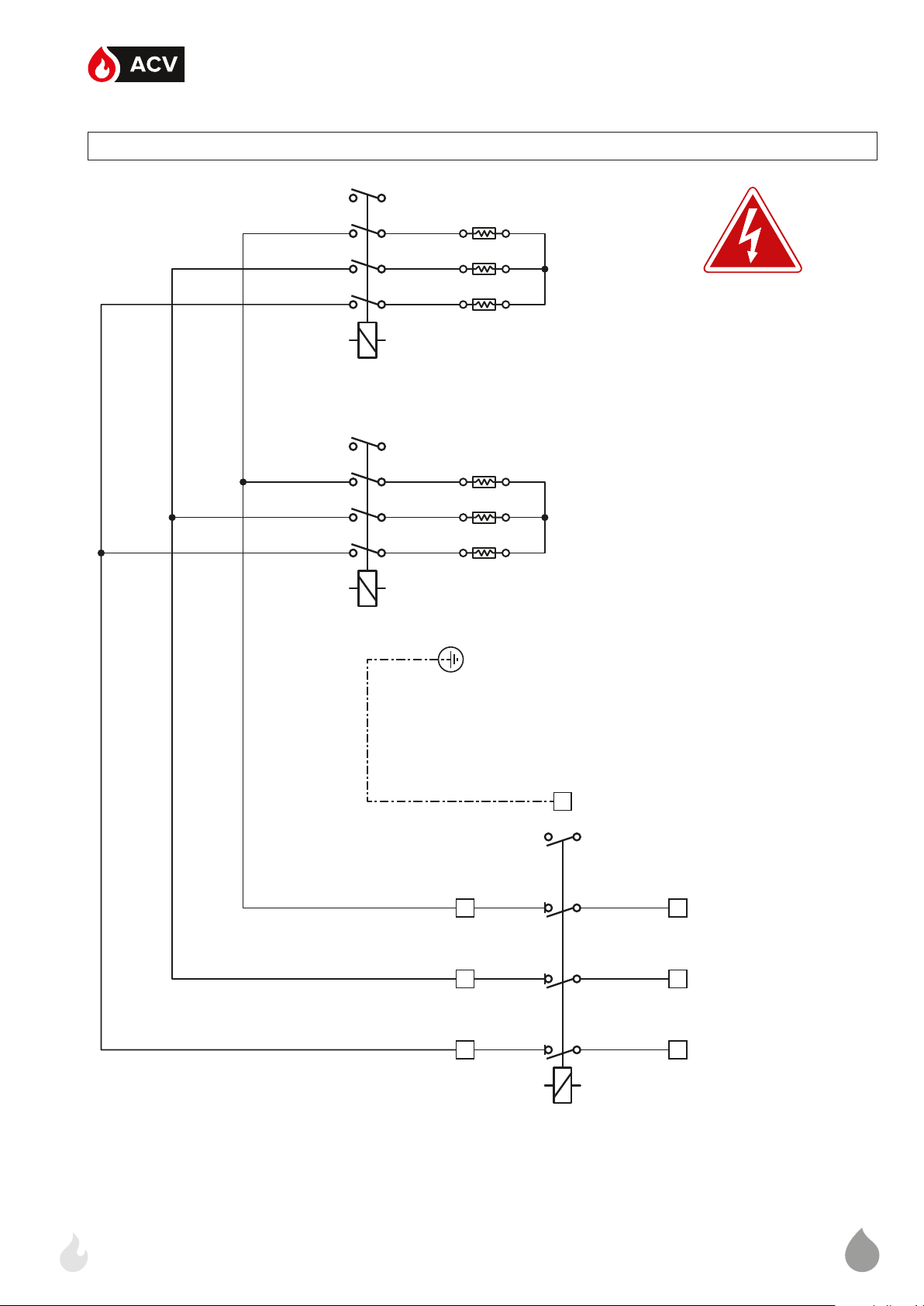
14
E-TECH W 09 - 15 TRI
ML
Power - Puissance - Vermogen - Potencia - Potenza - Leistung - Zasilania - Силовая часть
R
Bk
Or
R
Bk
Or
K1 K2
R
Bk
Or
R
Bk
OrB
B
B
B
B
B
B : Blue - Bleu - Blauw - Azul - Blu - Blau -Niebieski - Голубой
Bk : Black - Noir - Zwart - Negro - Nero - Schwarz - Czarny - Черный
Br : Brown - Brun - Bruin - Marrón - Marrone - Braun - Brązowy - Коричневый
G : Grey - Gris - Grijs - Gris - Grigio - Grau - Siwy - Серый
Or : Orange - Oranje - Naranja - Arancione - Pomarańczowy - Оранжевый
Pk : Pink - Rose - Roze - Rosa - Różowy - Розовый
R : Red - Rouge - Rood - Rojo - Rosso - Rot - Czerwony - Красный
W : White - Blanc - Wit - Blanco - Bianco - Weiß - Biał y - Белый
Y : Yellow - Jaune - Geel - Amarillo - Gallo - Gelb - Żółty - Желтый
PE
R
Bk
Or
S6
R
21 3
Bk
Or
R
Bk
Or
R
Bk
Or
L1 L2 L3
K3
Page 43

15
di 25A - Leistungsklemmen mit Sicherung 25A - Zaciski zasilania z zabezpieczeniem 25A - Клеммная колодка силовой цепи с предохранителями 25A
ML
Power relay 1 - level 1 - Relais de puissance 1 - étage 1 - Vermogensrelais 1 - trap 1 - Relé de potencia 1 - nivel 1 - Relè di potenza 1 - livello 1 - Leistung Relais 1 - Stufe 1 - Przekaźnik mocy 1 - poziom 1 -
Силовое реле 1 - ступень 1
Power relay 1 - level 2 - Relais de puissance 1 - étage 2 - Vermogensrelais 1 - trap 2 - Relé de potencia 1 - nivel 2 - Relè di potenza 1 - livello 2 - Leistung Relais 1 - Stufe 2 - Przekaźnik mocy 1 - poziom
2 - Силовое реле 1 - ступень 2
Power terminals with 25A fuse - Bornier de puissance avec fusible 25A - Vermogensklemmen met zekering van 25A - Bornes de potencia con fusible 25A - Morsettiera di potenza con fusibili
Safety switch - Contacteur de sécurité - Veiligheidscontact - Contactor de seguridad - Contattore di sicurezza - Sicherheitsrelais - Przekaźnik główny - Отключающее электромагнитное реле
S6
K1
K2
K3
Page 44
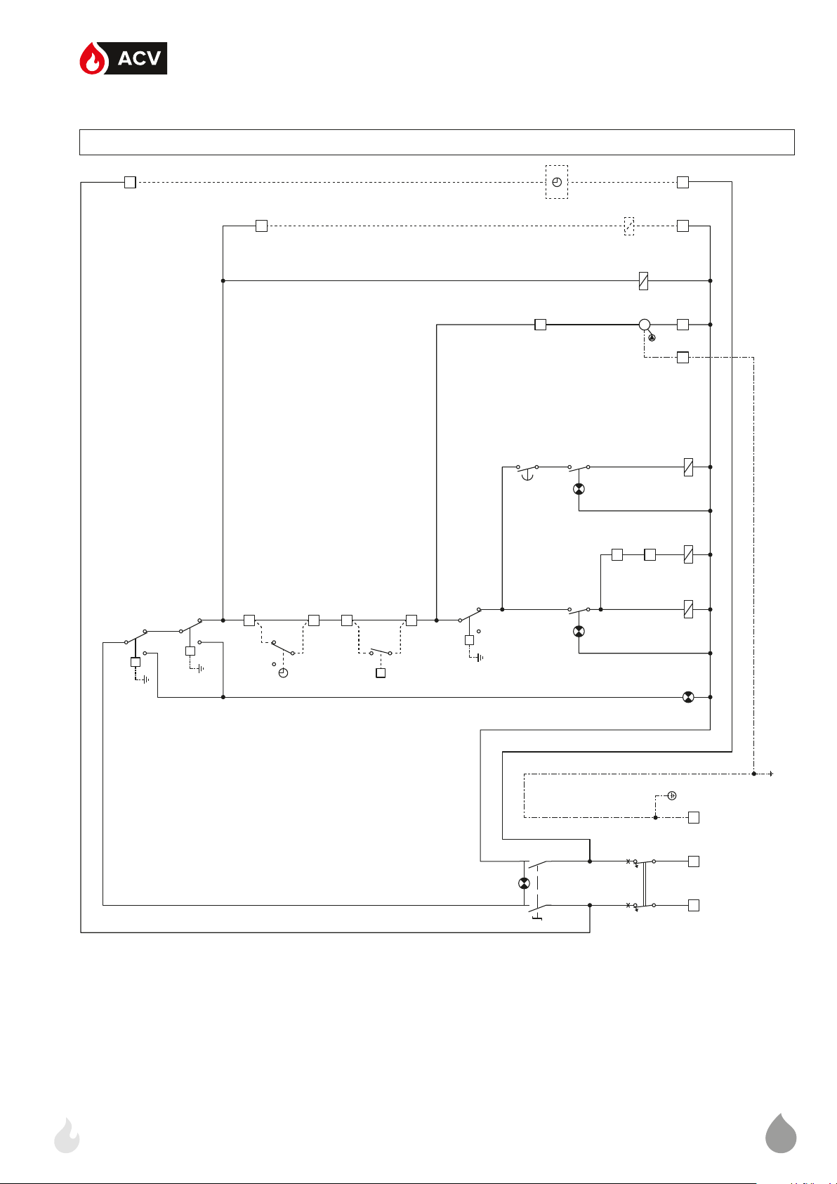
16
E-TECH W 22 TRI
ML
Control - Commande - Besturing - Mando - Comando - Kontrol - regulacja - регулирование
1
Br
3
OrOrR
1
B
B
K4
Or Or
9
S5
W
A1
A2
1.1
1.2
T1
2.2
B
Or
R
M
Pk
12
13
B
B
B Br G
11 10 4 2
B
B
B
B
W W
5
P
Br
P
Bk
2 1
t
S2
PS
P
OrYOr Y
2 1
6
7
7
P
8
Y
1
t
C
GG Or
S3
2 1
t
B
Or Or
B
B
S4
1.1
1.2
2.2
B
B
S1
1.2 2.2
1.1 2.1
Bk Bk
Br
Br
R
R RR
4
B
CB
Br
2
K1 K3 K2
B
B
DS1
B
B
PE
3
B
1 2
Br
1
- Blu - Blau -Niebieski -
Голубой
Negro - Nero - Schwarz
- Czarny - Черный
Marrón - Marrone - Braun
- Brązowy - Коричневый
- Grigio - Grau - Siwy -
Серый
Naranja - Arancione
- Pomarańczowy -
Оранжевый
- Różowy - Розовый
- Rojo - Rosso - Rot -
Czerwony - Красный
Blanco - Bianco - Weiß -
Biały - Белый
Amarillo - Gallo - Gelb -
Żółty - Желтый
B : Blue - Bleu - Blauw - Azul
Bk : Black - Noir - Zwart -
Br : Brown - Brun - Bruin -
G : Grey - Gris - Grijs - Gris
Or : Orange - Oranje -
Pk : Pink - Rose - Roze - Rosa
R : Red - Rouge - Rood
W : White - Blanc - Wit -
Y : Yellow - Jaune - Geel -
Page 45

17
étage + lampe - Vermogenschakelaar 1 + lampje - Interruptor del primer nivel + luz - Interruttore luminoso del primo livello di poten-
ML
er
управления
wyłącznik + lampa - Переключатель ВКЛ/ВЫКЛ + лампы
de rearme manual [103°C] - Termostato di sicurezza a riarmo manuale [103°C] - Manuell entriegelbares Sicherheitsthermostat [103°C] - Termostat bezpieczeństwa z ręcznym odblokowaniem
[103°C] - Защитный термостат с ручным перезапуском [103°C]
mancanza acqua - Wassermangelsicherung - Czujnik ciśnienia wody - Реле минимального давления
CB Circuit breaker - Disjoncteur - Magnetothermische Schakelaar - Disyuntor magnetotérmico - Interruttore magnetotermico generale ON/OFF - Sicherung - Bezpiecznik obwodu regulacji - Цепь
S1 ON/OFF switch + lamp - Interrupteur ON/OFF + lampe - ON/OFF- schakelaar + lampje - Interruptor ON/OFF + luz - Interruttore luminoso ON/OFF - ON/OFF-Schalter + Leuchte - ON/OFF zał/
S2 Manual reset safety thermostat [103°C] - Thermostat de sécurité à réarmement manuel [103°C] - Veiligheidsthermostaat met handmatige herinschakeling [103°C] - Termostato de seguridad
PS Low-water pressure switch - Pressostat de sécurité manque d’eau - Veiligheidsdrukschakelaar watergebrek - Presostato de seguridad en caso de falta de agua - Pressostato di sicurezza
DS1 Alarm - Signal de mise en sécurité - Alarm - Alarma - Allarme - Alarm - Alarm - Сигнализация
S3 Control thermostat - Thermostat de commande - Regelthermostaat - Termostato de mando - Termostato di comando - Einstellthermostat - Termostat kotłowy - Регулировочный термостат
za - Stufenschalter 1 + Leuchte - Przełącznik poziomu mocy 1 + lampa - Переключатель уровня мощности - ступень1 + лампы
ziom 1 - Силовое реле 1 - ступень 1
2 - poziom 1 - Силовое реле 2 - ступень 1
K1 Power relay 1 - level 1 - Relais de puissance 1 - étage 1 - Vermogensrelais 1 - trap 1 - Relé de potencia 1 - nivel 1 - Relè di potenza 1 - livello 1 - Leistung Relais 1 - Stufe 1 - Przekaźnik mocy 1 - po-
S4 Power switch level 1 + lamp - Commutateur de puissance 1
K3 Power relay 2 - level 1 - Relais de puissance 2 - étage 1 - Vermogensrelais 2 - trap 1 - Relé de potencia 2 - nivel 1 - Relè di potenza 2 - livello 1 - Leistung Relais 2 - Stufe 1 - Przekaźnik mocy
T1 Timer - Temporisateur - Timer - Temporizador - Temporizzatore - Zeitschalter - Przekaźnik czasowy - Реле времени включения второй ступени
éme
di potenza - Stufenschalter 2 + Leuchte - Przełącznik poziomu mocy 2 + lampa - Переключатель уровня мощности - ступень2 + лампы
- poziom 2 - Силовое реле 1 - ступень 2
реле
(optioneel) - Alimentación eléctrica para optimizador o regulador (opcional) - Alimentazione elettrica per un regolatore o per un orologio per programmazione giornaliera (in opzione) - Strom
Versorgung für Schaltuhr oder Regler (Optional) - Zasilanie z zegara czasowego (opcja) - Перемычка или таймер часов работы (опция)
S5 Power switch level 2 + lamp - Commutateur de puissance 2
K2 Power relay 1 - level 2 - Relais de puissance 1 - étage 2 - Vermogensrelais 1 - trap 2 - Relé de potencia 1 - nivel 2 - Relè di potenza 1 - livello 2 - Leistung Relais 1 - Stufe 2 - Przekaźnik mocy 1
K4 Safety switch - Contacteur de sécurité - Veiligheidscontact - Contactor de seguridad - Contattore di sicurezza - Sicherheitsrelais - Przekaźnik główny - Отключающее электромагнитное
1-2 Time clock or controller supply (optional) - Alimentation électrique pour un régulateur ou un programmateur journalier optionnel - Voedingsspanning voor Schakelklok of externeregeling
3-4 DHW kit (optional) - Kit sanitaire (en option) - Sanitaire kit (optioneel) - Kit sanitario (opcional) - Kit sanitario (opzionale) - Sanitärer Satz (Optional) - Zestaw CWU (opcja) - ГВС комплект (опция)
parada general o interruptor del optimizador (opcional) - Ponte di arresto generale o comando di un orologio per programmazione giornaliera
(in opzione) - Schaltuhr oder Regler Eingang (Optional) - Mostek wyłączający lub wyłącznik czasowy (opcja) - Перемычка или таймер часов работы (опция)
(Optional) - Termostat pokojowy (opcja) - Комнатный термостат (опция)
5-6 Stop Bridge or time clock switch control (optional) - Pont d’arrêt général ou commande du programmateur journalier optionnel - Aansluiting Schakelklok of regeling (optioneel) - Puente de
7-8 Room thermostat (optional) - Thermostat d’ambiance (en option) - Omgevingsthermostaat (optioneel) - Termostato de ambiente (opcional) - Termostato ambiente (opzionale) - Raumthermostat
9-10-11 Heating pump - Pompe chauffage - Warmtepomp - Circulador de calefacción - Circolatore di riscaldamento - Heizpumpe - Pompa kotła - Насос котла
ничения мощности
12-13 Relay K3 deactivated - Relais K3 désactivé - Desactivering van relais K3 - Descarga del relé K3 - Esclusione del relè K3 - Abschaltung Relais K3 - Mostek przekaźnika K3 - Перемычка огра-
étage + lampe - Vermogenschakelaar 2 + lampje - Interruptor del segundo nivel + luz - Interruttore luminoso del secondo livello
Page 46

18
E-TECH W 22 TRI
ML
Power - Puissance - Vermogen - Potencia - Potenza - Leistung - Zasilania - Силовая часть
R
R
Bk
Bk
Br
Br
R
R
Bk
Bk
Br
Br
B
B
B
B
B
B
R
R
Bk
Bk
Br
BrB
B
B
K1 K2 K3
B : Blue - Bleu - Blauw - Azul - Blu - Blau -Niebieski - Голубой
Bk : Black - Noir - Zwart - Negro - Nero - Schwarz - Czarny - Черный
Br : Brown - Brun - Bruin - Marrón - Marrone - Braun - Brązowy - Коричневый
G : Grey - Gris - Grijs - Gris - Grigio - Grau - Siwy - Серый
Or : Orange - Oranje - Naranja - Arancione - Pomarańczowy - Оранжевый
Pk : Pink - Rose - Roze - Rosa - Różowy - Розовый
R : Red - Rouge - Rood - Rojo - Rosso - Rot - Czerwony - Красный
W : White - Blanc - Wit - Blanco - Bianco - Weiß - Biał y - Белый
Y : Yellow - Jaune - Geel - Amarillo - Gallo - Gelb - Żółty - Желтый
PE
R
R
Bk
Bk
Br
Br
S6
R
R
Bk
321 4 5 6
Bk
Br
Br
R
Bk
Br
R
Bk
Br
L1 L2 L3
K4
Page 47
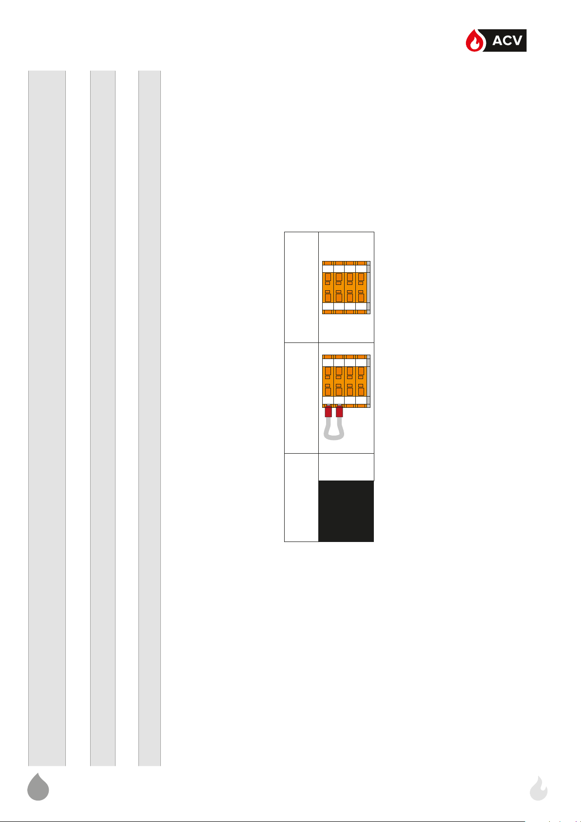
19
E-Tech W 22 21.6 kW 14.4 kW
12121313141415
15
12121313141415
15
ML
Tri Phase TB1
di 25A - Leistungsklemmen mit Sicherung 25A - Zaciski zasilania z zabezpieczeniem 25A - Клеммная колодка силовой цепи с предохранителями 25A
Power relay 1 - level 1 - Relais de puissance 1 - étage 1 - Vermogensrelais 1 - trap 1 - Relé de potencia 1 - nivel 1 - Relè di potenza 1 - livello 1 - Leistung Relais 1 - Stufe 1 - Przekaźnik mocy 1 - poziom 1 -
Силовое реле 1 - ступень 1
Power relay 1 - level 2 - Relais de puissance 1 - étage 2 - Vermogensrelais 1 - trap 2 - Relé de potencia 1 - nivel 2 - Relè di potenza 1 - livello 2 - Leistung Relais 1 - Stufe 2 - Przekaźnik mocy 1 - poziom
2 - Силовое реле 1 - ступень 2
Power relay 2 - level 1 - Relais de puissance 2 - étage 1 - Vermogensrelais 2 - trap 1 - Relé de potencia 2 - nivel 1 - Relè di potenza 2 - livello 1 - Leistung Relais 2 - Stufe 1 - Przekaźnik mocy 2 - poziom
1 - Силовое реле 2 - ступень 1
Power terminals with 25A fuse - Bornier de puissance avec fusible 25A - Vermogensklemmen met zekering van 25A - Bornes de potencia con fusible 25A - Morsettiera di potenza con fusibili
Safety switch - Contacteur de sécurité - Veiligheidscontact - Contactor de seguridad - Contattore di sicurezza - Sicherheitsrelais - Przekaźnik główny - Отключающее электромагнитное реле
S6
K1
K2
K3
K4
Page 48

20
E-TECH W 28 TRI
ML
Control - Commande - Besturing - Mando - Comando - Kontrol - regulacja - регулирование
1
Br
3
OrOrR
1
B
B
K5
Or Or
9
PkR
S5
W
A1
A2
1.1
1.2
T1
2.2
B
Or
M
W
14
15
Pk
W
12
13
B
B
B Br G
11 10 4 2
B
W
B
B
B
W
B
5
P
Br
P
Bk
2 1
t
S2
PS
P
OrYOr Y
2 1
6
7
7
P
8
Y
1
t
C
GG Or
S3
2 1
t
B
Or Or
B
B
S4
1.1
1.2
2.2
B
B
S1
1.2 2.2
1.1 2.1
Bk Bk
Br
Br
R
R RR
4
B
CB
Br
2
K1 K3 K2 K4
B
B
DS1
B
B
PE
3
B
1 2
Br
1
- Blu - Blau -Niebieski -
Голубой
Negro - Nero - Schwarz
- Czarny - Черный
Marrón - Marrone - Braun
- Brązowy - Коричневый
- Grigio - Grau - Siwy -
Серый
Naranja - Arancione
- Pomarańczowy -
B : Blue - Bleu - Blauw - Azul
Bk : Black - Noir - Zwart -
Br : Brown - Brun - Bruin -
G : Grey - Gris - Grijs - Gris
Or : Orange - Oranje -
- Różowy - Розовый
- Rojo - Rosso - Rot -
Czerwony - Красный
Blanco - Bianco - Weiß -
Biały - Белый
Amarillo - Gallo - Gelb -
Оранжевый
Pk : Pink - Rose - Roze - Rosa
R : Red - Rouge - Rood
W : White - Blanc - Wit -
Żółty - Желтый
Y : Yellow - Jaune - Geel -
Page 49

21
étage + lampe - Vermogenschakelaar 1 + lampje - Interruptor del primer nivel + luz - Interruttore luminoso del primo livello di poten-
ML
er
Circuit breaker - Disjoncteur - Magnetothermische Schakelaar - Disyuntor magnetotérmico - Interruttore magnetotermico generale ON/OFF - Sicherung - Bezpiecznik obwodu regulacji - Цепь
управления
ON/OFF switch + lamp - Interrupteur ON/OFF + lampe - ON/OFF- schakelaar + lampje - Interruptor ON/OFF + luz - Interruttore luminoso ON/OFF - ON/OFF-Schalter + Leuchte - ON/OFF zał/
wyłącznik + lampa - Переключатель ВКЛ/ВЫКЛ + лампы
Manual reset safety thermostat [103°C] - Thermostat de sécurité à réarmement manuel [103°C] - Veiligheidsthermostaat met handmatige herinschakeling [103°C] - Termostato de seguridad
de rearme manual [103°C] - Termostato di sicurezza a riarmo manuale [103°C] - Manuell entriegelbares Sicherheitsthermostat [103°C] - Termostat bezpieczeństwa z ręcznym odblokowaniem
[103°C] - Защитный термостат с ручным перезапуском [103°C]
Low-water pressure switch - Pressostat de sécurité manque d’eau - Veiligheidsdrukschakelaar watergebrek - Presostato de seguridad en caso de falta de agua - Pressostato di sicurezza
mancanza acqua - Wassermangelsicherung - Czujnik ciśnienia wody - Реле минимального давления
Alarm - Signal de mise en sécurité - Alarm - Alarma - Allarme - Alarm - Alarm - Сигнализация
Control thermostat - Thermostat de commande - Regelthermostaat - Termostato de mando - Termostato di comando - Einstellthermostat - Termostat kotłowy - Регулировочный термостат
Power switch level 1 + lamp - Commutateur de puissance 1
za - Stufenschalter 1 + Leuchte - Przełącznik poziomu mocy 1 + lampa - Переключатель уровня мощности - ступень1 + лампы
Power relay 1 - level 1 - Relais de puissance 1 - étage 1 - Vermogensrelais 1 - trap 1 - Relé de potencia 1 - nivel 1 - Relè di potenza 1 - livello 1 - Leistung Relais 1 - Stufe 1 - Przekaźnik mocy 1 - po-
ziom 1 - Силовое реле 1 - ступень 1
Power relay 2 - level 1 - Relais de puissance 2 - étage 1 - Vermogensrelais 2 - trap 1 - Relé de potencia 2 - nivel 1 - Relè di potenza 2 - livello 1 - Leistung Relais 2 - Stufe 1 - Przekaźnik mocy
2 - poziom 1 - Силовое реле 2 - ступень 1T1Timer - Temporisateur - Timer - Temporizador - Temporizzatore - Zeitschalter - Przekaźnik czasowy - Реле времени включения второй ступени
éme
Power switch level 2 + lamp - Commutateur de puissance 2
di potenza - Stufenschalter 2 + Leuchte - Przełącznik poziomu mocy 2 + lampa - Переключатель уровня мощности - ступень2 + лампы
Power relay 1 - level 2 - Relais de puissance 1 - étage 2 - Vermogensrelais 1 - trap 2 - Relé de potencia 1 - nivel 2 - Relè di potenza 1 - livello 2 - Leistung Relais 1 - Stufe 2 - Przekaźnik mocy 1
- poziom 2 - Силовое реле 1 - ступень 2
Power relay 2 - level 2 - Relais de puissance 2 - étage 2 - Vermogensrelais 2 - trap 2 - Relé de potencia 2 - nivel 2 - Relè di potenza 2 - livello 2 - Leistung Relais 2 - Stufe 2 - Przekaźnik mocy
2 - poziom 2 - Силовое реле 2 - ступень 2
Safety switch - Contacteur de sécurité - Veiligheidscontact - Contactor de seguridad - Contattore di sicurezza - Sicherheitsrelais - Przekaźnik główny - Отключающее электромагнитное
реле
Time clock or controller supply (optional) - Alimentation électrique pour un régulateur ou un programmateur journalier optionnel - Voedingsspanning voor Schakelklok of externeregeling
(optioneel) - Alimentación eléctrica para optimizador o regulador (opcional) - Alimentazione elettrica per un regolatore o per un orologio per programmazione giornaliera (in opzione) - Strom
Versorgung für Schaltuhr oder Regler (Optional) - Zasilanie z zegara czasowego (opcja) - Перемычка или таймер часов работы (опция)
DHW kit (optional) - Kit sanitaire (en option) - Sanitaire kit (optioneel) - Kit sanitario (opcional) - Kit sanitario (opzionale) - Sanitärer Satz (Optional) - Zestaw CWU (opcja) - ГВС комплект (опция)
Stop Bridge or time clock switch control (optional) - Pont d’arrêt général ou commande du programmateur journalier optionnel - Aansluiting Schakelklok of regeling (optioneel) - Puente de
parada general o interruptor del optimizador (opcional) - Ponte di arresto generale o comando di un orologio per programmazione giornaliera
Room thermostat (optional) - Thermostat d’ambiance (en option) - Omgevingsthermostaat (optioneel) - Termostato de ambiente (opcional) - Termostato ambiente (opzionale) - Raumthermostat
(Optional) - Termostat pokojowy (opcja) - Комнатный термостат (опция)
(in opzione) - Schaltuhr oder Regler Eingang (Optional) - Mostek wyłączający lub wyłącznik czasowy (opcja) - Перемычка или таймер часов работы (опция)
Heating pump - Pompe chauffage - Warmtepomp - Circulador de calefacción - Circolatore di riscaldamento - Heizpumpe - Pompa kotła - Насос котла
ничения мощности
Relay K3 deactivated - Relais K3 désactivé - Desactivering van relais K3 - Descarga del relé K3 - Esclusione del relè K3 - Abschaltung Relais K3 - Mostek przekaźnika K3 - Перемычка огра-
чения мощности
Relay K4 deactivated - Relais K4 désactivé - Desactivering van relais K4 - Descarga del relé K4 - Esclusione del relè K4 - Abschaltung Relais K4 - Mostek przekaźnika K4 - Перемычка ограни-
étage + lampe - Vermogenschakelaar 2 + lampje - Interruptor del segundo nivel + luz - Interruttore luminoso del secondo livello
CB
S1
S2
PS
DS1
S3
K1
S4
K3
S5
K2
K4
K5
1-2
3-4
5-6
7-8
9-10-11
12-13
14-15
Page 50

22
E-TECH W 28 TRI
ML
Power - Puissance - Vermogen - Potencia - Potenza - Leistung - Zasilania - Силовая часть
R
R
Bk
Bk
Br
Br
R
R
Bk
Bk
Br
Br
R
R
Bk
Bk
Br
Br
B
B
B
B
B
B
B
B
B
R
R
Bk
Bk
Br
BrB
K1 K2 K3 K4
B
B
B : Blue - Bleu - Blauw - Azul - Blu - Blau -Niebieski - Голубой
Bk : Black - Noir - Zwart - Negro - Nero - Schwarz - Czarny - Черный
Br : Brown - Brun - Bruin - Marrón - Marrone - Braun - Brązowy - Коричневый
G : Grey - Gris - Grijs - Gris - Grigio - Grau - Siwy - Серый
Or : Orange - Oranje - Naranja - Arancione - Pomarańczowy - Оранжевый
Pk : Pink - Rose - Roze - Rosa - Różowy - Розовый
R : Red - Rouge - Rood - Rojo - Rosso - Rot - Czerwony - Красный
W : White - Blanc - Wit - Blanco - Bianco - Weiß - Biał y - Белый
Y : Yellow - Jaune - Geel - Amarillo - Gallo - Gelb - Żółty - Желтый
PE
R
R
Bk
Bk
Br
Br
S6
R
R
Bk
321 4 5 6
Bk
Br
Br
R
Bk
Br
R
Bk
Br
L1 L2 L3
K5
Page 51

23
12121313141415
15
12121313141415
15
12121313141415
15
ML
E-Tech W 28 28.8 kW 21.6 kW 14.4 kW
Tri Phase TB1
di 25A - Leistungsklemmen mit Sicherung 25A - Zaciski zasilania z zabezpieczeniem 25A - Клеммная колодка силовой цепи с предохранителями 25A
Power relay 1 - level 1 - Relais de puissance 1 - étage 1 - Vermogensrelais 1 - trap 1 - Relé de potencia 1 - nivel 1 - Relè di potenza 1 - livello 1 - Leistung Relais 1 - Stufe 1 - Przekaźnik mocy 1 - poziom 1 -
Силовое реле 1 - ступень 1
Power relay 1 - level 2 - Relais de puissance 1 - étage 2 - Vermogensrelais 1 - trap 2 - Relé de potencia 1 - nivel 2 - Relè di potenza 1 - livello 2 - Leistung Relais 1 - Stufe 2 - Przekaźnik mocy 1 - poziom
2 - Силовое реле 1 - ступень 2
Power relay 2 - level 1 - Relais de puissance 2 - étage 1 - Vermogensrelais 2 - trap 1 - Relé de potencia 2 - nivel 1 - Relè di potenza 2 - livello 1 - Leistung Relais 2 - Stufe 1 - Przekaźnik mocy 2 - poziom
1 - Силовое реле 2 - ступень 1
Power relay 2 - level 2 - Relais de puissance 2 - étage 2 - Vermogensrelais 2 - trap 2 - Relé de potencia 2 - nivel 2 - Relè di potenza 2 - livello 2 - Leistung Relais 2 - Stufe 2 - Przekaźnik mocy 2
- poziom 2 - Силовое реле 2 - ступень 2
Power terminals with 25A fuse - Bornier de puissance avec fusible 25A - Vermogensklemmen met zekering van 25A - Bornes de potencia con fusible 25A - Morsettiera di potenza con fusibili
S6
K1
K2
K3
Safety switch - Contacteur de sécurité - Veiligheidscontact - Contactor de seguridad - Contattore di sicurezza - Sicherheitsrelais - Przekaźnik główny - Отключающее электромагнитное реле
K4
K5
Page 52

24
E-TECH W 36 TRI
Br
ML
Control - Commande - Besturing - Mando - Comando - Kontrol - regulacja - регулирование
1
Br
3
OrOrR
1
B
B
K5
Or Or
9
PkR
S5
W
A1
A2
1.1
1.2
T1
2.2
B
Or
M
W
14
15
Pk
W
12
13
B
B
B Br G
11 10 4 2
B
W
B
B
B
W
B
5
P
Br
P
Bk
2 1
t
S2
PS
P
OrYOr Y
2 1
6
7
7
P
8
Y
1
t
C
GG Or
S3
2 1
t
B
Or Or
B
B
S4
1.1
1.2
2.2
B
B
S1
1.2 2.2
1.1 2.1
Bk Bk
Br
R
R RR
4
B
CB
Br
2
K1 K3 K2 K4
B
B
DS1
B
B
PE
3
B
1 2
Br
1
- Blu - Blau -Niebieski -
Голубой
Negro - Nero - Schwarz
- Czarny - Черный
Marrón - Marrone - Braun
- Brązowy - Коричневый
- Grigio - Grau - Siwy -
Серый
Naranja - Arancione
- Pomarańczowy -
Оранжевый
- Różowy - Розовый
- Rojo - Rosso - Rot -
Czerwony - Красный
Blanco - Bianco - Weiß -
Biały - Белый
Amarillo - Gallo - Gelb -
Żółty - Желтый
B : Blue - Bleu - Blauw - Azul
Bk : Black - Noir - Zwart -
Br : Brown - Brun - Bruin -
G : Grey - Gris - Grijs - Gris
Or : Orange - Oranje -
Pk : Pink - Rose - Roze - Rosa
R : Red - Rouge - Rood
W : White - Blanc - Wit -
Y : Yellow - Jaune - Geel -
Page 53

25
étage + lampe - Vermogenschakelaar 1 + lampje - Interruptor del primer nivel + luz - Interruttore luminoso del primo livello di poten-
ML
er
Circuit breaker - Disjoncteur - Magnetothermische Schakelaar - Disyuntor magnetotérmico - Interruttore magnetotermico generale ON/OFF - Sicherung - Bezpiecznik obwodu regulacji - Цепь
управления
ON/OFF switch + lamp - Interrupteur ON/OFF + lampe - ON/OFF- schakelaar + lampje - Interruptor ON/OFF + luz - Interruttore luminoso ON/OFF - ON/OFF-Schalter + Leuchte - ON/OFF zał/
wyłącznik + lampa - Переключатель ВКЛ/ВЫКЛ + лампы
Manual reset safety thermostat [103°C] - Thermostat de sécurité à réarmement manuel [103°C] - Veiligheidsthermostaat met handmatige herinschakeling [103°C] - Termostato de seguridad
de rearme manual [103°C] - Termostato di sicurezza a riarmo manuale [103°C] - Manuell entriegelbares Sicherheitsthermostat [103°C] - Termostat bezpieczeństwa z ręcznym odblokowaniem
[103°C] - Защитный термостат с ручным перезапуском [103°C]
Low-water pressure switch - Pressostat de sécurité manque d’eau - Veiligheidsdrukschakelaar watergebrek - Presostato de seguridad en caso de falta de agua - Pressostato di sicurezza
mancanza acqua - Wassermangelsicherung - Czujnik ciśnienia wody - Реле минимального давления
Alarm - Signal de mise en sécurité - Alarm - Alarma - Allarme - Alarm - Alarm - Сигнализация
Control thermostat - Thermostat de commande - Regelthermostaat - Termostato de mando - Termostato di comando - Einstellthermostat - Termostat kotłowy - Регулировочный термостат
Power switch level 1 + lamp - Commutateur de puissance 1
za - Stufenschalter 1 + Leuchte - Przełącznik poziomu mocy 1 + lampa - Переключатель уровня мощности - ступень1 + лампы
Power relay 1 - level 1 - Relais de puissance 1 - étage 1 - Vermogensrelais 1 - trap 1 - Relé de potencia 1 - nivel 1 - Relè di potenza 1 - livello 1 - Leistung Relais 1 - Stufe 1 - Przekaźnik mocy 1 - po-
ziom 1 - Силовое реле 1 - ступень 1
Power relay 2 - level 1 - Relais de puissance 2 - étage 1 - Vermogensrelais 2 - trap 1 - Relé de potencia 2 - nivel 1 - Relè di potenza 2 - livello 1 - Leistung Relais 2 - Stufe 1 - Przekaźnik mocy
2 - poziom 1 - Силовое реле 2 - ступень 1T1Timer - Temporisateur - Timer - Temporizador - Temporizzatore - Zeitschalter - Przekaźnik czasowy - Реле времени включения второй ступени
éme
Power switch level 2 + lamp - Commutateur de puissance 2
di potenza - Stufenschalter 2 + Leuchte - Przełącznik poziomu mocy 2 + lampa - Переключатель уровня мощности - ступень2 + лампы
Power relay 1 - level 2 - Relais de puissance 1 - étage 2 - Vermogensrelais 1 - trap 2 - Relé de potencia 1 - nivel 2 - Relè di potenza 1 - livello 2 - Leistung Relais 1 - Stufe 2 - Przekaźnik mocy 1
- poziom 2 - Силовое реле 1 - ступень 2
Power relay 2 - level 2 - Relais de puissance 2 - étage 2 - Vermogensrelais 2 - trap 2 - Relé de potencia 2 - nivel 2 - Relè di potenza 2 - livello 2 - Leistung Relais 2 - Stufe 2 - Przekaźnik mocy
2 - poziom 2 - Силовое реле 2 - ступень 2
Safety switch - Contacteur de sécurité - Veiligheidscontact - Contactor de seguridad - Contattore di sicurezza - Sicherheitsrelais - Przekaźnik główny - Отключающее электромагнитное
реле
Time clock or controller supply (optional) - Alimentation électrique pour un régulateur ou un programmateur journalier optionnel - Voedingsspanning voor Schakelklok of externeregeling
(optioneel) - Alimentación eléctrica para optimizador o regulador (opcional) - Alimentazione elettrica per un regolatore o per un orologio per programmazione giornaliera (in opzione) - Strom
Versorgung für Schaltuhr oder Regler (Optional) - Zasilanie z zegara czasowego (opcja) - Перемычка или таймер часов работы (опция)
DHW kit (optional) - Kit sanitaire (en option) - Sanitaire kit (optioneel) - Kit sanitario (opcional) - Kit sanitario (opzionale) - Sanitärer Satz (Optional) - Zestaw CWU (opcja) - ГВС комплект (опция)
Stop Bridge or time clock switch control (optional) - Pont d’arrêt général ou commande du programmateur journalier optionnel - Aansluiting Schakelklok of regeling (optioneel) - Puente de
parada general o interruptor del optimizador (opcional) - Ponte di arresto generale o comando di un orologio per programmazione giornaliera
Room thermostat (optional) - Thermostat d’ambiance (en option) - Omgevingsthermostaat (optioneel) - Termostato de ambiente (opcional) - Termostato ambiente (opzionale) - Raumthermostat
(Optional) - Termostat pokojowy (opcja) - Комнатный термостат (опция)
(in opzione) - Schaltuhr oder Regler Eingang (Optional) - Mostek wyłączający lub wyłącznik czasowy (opcja) - Перемычка или таймер часов работы (опция)
Heating pump - Pompe chauffage - Warmtepomp - Circulador de calefacción - Circolatore di riscaldamento - Heizpumpe - Pompa kotła - Насос котла
ничения мощности
Relay K3 deactivated - Relais K3 désactivé - Desactivering van relais K3 - Descarga del relé K3 - Esclusione del relè K3 - Abschaltung Relais K3 - Mostek przekaźnika K3 - Перемычка огра-
чения мощности
Relay K4 deactivated - Relais K4 désactivé - Desactivering van relais K4 - Descarga del relé K4 - Esclusione del relè K4 - Abschaltung Relais K4 - Mostek przekaźnika K4 - Перемычка ограни-
étage + lampe - Vermogenschakelaar 2 + lampje - Interruptor del segundo nivel + luz - Interruttore luminoso del secondo livello
CB
S1
S2
PS
DS1
S3
K1
S4
K3
S5
K2
K4
K5
1-2
3-4
5-6
7-8
9-10-11
12-13
14-15
Page 54

26
E-TECH W 36 TRI
Br
ML
Power - Puissance - Vermogen - Potencia - Potenza - Leistung - Zasilania - Силовая часть
R
R
Bk
Bk
Br
Br
R
R
Bk
Bk
Br
Br
R
R
Bk
Bk
Br
Br
B
B
B
B
B
B
B
B
B
R
R
Bk
Bk
Br
Br
B
B
B
K1 K2 K3 K4
B : Blue - Bleu - Blauw - Azul - Blu - Blau -Niebieski - Голубой
Bk : Black - Noir - Zwart - Negro - Nero - Schwarz - Czarny - Черный
Br : Brown - Brun - Bruin - Marrón - Marrone - Braun - Brązowy - Коричневый
G : Grey - Gris - Grijs - Gris - Grigio - Grau - Siwy - Серый
Or : Orange - Oranje - Naranja - Arancione - Pomarańczowy - Оранжевый
Pk : Pink - Rose - Roze - Rosa - Różowy - Розовый
R : Red - Rouge - Rood - Rojo - Rosso - Rot - Czerwony - Красный
W : White - Blanc - Wit - Blanco - Bianco - Weiß - Biał y - Белый
Y : Yellow - Jaune - Geel - Amarillo - Gallo - Gelb - Żółty - Желтый
PE
R
R
Bk
Bk
Br
2
R
2
R
2
Bk
2
Bk
2
Br
2
Br
S6
1
1
1
1
1
1
(F32A)
R
R
R
Bk
Bk
Bk
Br
Br
Br
R
Bk
Br
L1 L2 L3
K5
Page 55

27
12121313141415
15
12121313141415
15
12121313141415
15
ML
E-Tech W 36 36 kW 27 kW 18 kW
Tri Phase TB1
di 25A - Leistungsklemmen mit Sicherung 25A - Zaciski zasilania z zabezpieczeniem 25A - Клеммная колодка силовой цепи с предохранителями 25A
Power relay 1 - level 1 - Relais de puissance 1 - étage 1 - Vermogensrelais 1 - trap 1 - Relé de potencia 1 - nivel 1 - Relè di potenza 1 - livello 1 - Leistung Relais 1 - Stufe 1 - Przekaźnik mocy 1 - poziom 1 -
Силовое реле 1 - ступень 1
Power relay 1 - level 2 - Relais de puissance 1 - étage 2 - Vermogensrelais 1 - trap 2 - Relé de potencia 1 - nivel 2 - Relè di potenza 1 - livello 2 - Leistung Relais 1 - Stufe 2 - Przekaźnik mocy 1 - poziom
2 - Силовое реле 1 - ступень 2
Power relay 2 - level 1 - Relais de puissance 2 - étage 1 - Vermogensrelais 2 - trap 1 - Relé de potencia 2 - nivel 1 - Relè di potenza 2 - livello 1 - Leistung Relais 2 - Stufe 1 - Przekaźnik mocy 2 - poziom
1 - Силовое реле 2 - ступень 1
Power relay 2 - level 2 - Relais de puissance 2 - étage 2 - Vermogensrelais 2 - trap 2 - Relé de potencia 2 - nivel 2 - Relè di potenza 2 - livello 2 - Leistung Relais 2 - Stufe 2 - Przekaźnik mocy 2
- poziom 2 - Силовое реле 2 - ступень 2
Power terminals with 25A fuse - Bornier de puissance avec fusible 25A - Vermogensklemmen met zekering van 25A - Bornes de potencia con fusible 25A - Morsettiera di potenza con fusibili
S6
K1
K2
K3
Safety switch - Contacteur de sécurité - Veiligheidscontact - Contactor de seguridad - Contattore di sicurezza - Sicherheitsrelais - Przekaźnik główny - Отключающее электромагнитное реле
K4
K5
Page 56

28
1
ML
2
3
6
7
10
4
5
8
9
14
15
11
12
13
12
16
17
18
Page 57

29
EN FR NL DE
ML
1. Top cover
2. Dry well
3. Side panel
4. Power supply cable
gland
5. Control panel
6. Automatic air vent
7. Heating elements
8. Heating body
9. Safety valve
10. Rear panel
11. Low water safety switch
12. Expansion vessel connection
13. Heating return
14. Expansion vessel
15. Expansion vessel valve
16. Circulating pump
17. Heating supply
18. Manual reset high limit
thermostat
1. Couvercle supérieur
2. Doigt de gant
3. Jaquette latérale
4. Presse-étoupe d’alimentation
5. Tableau de commande
6. Purgeur automatique
7. Éléments électriques
8. Corps de chaue
9. Soupape de sécurité
10. Panneau arrière
11. Pressostat de sécurité
manque d’eau
12. Raccordement du vase
d’expansion
13. Retour chauage
14. Vase d’expansion
15. Soupape du vase d’expansion
16. Circulateur
17. Départ chauage
18. Thermostat de sécurité
manuel
1. Bovenkap
2. Voelerhuls
3. Zijommanteling
4. Fitting voor voedingskabel
5. Bedieningspaneel
6. Automatische ontluchter
7. Elektrische elementen
8. Ketellichaam
9. Veiligheidsklep
10. Achterpaneel
11. Veiligheidsdrukschakelaar watergebrek
12. Aansluiting van het expansievat
13. Terugvoer verwarming
14. Expansievat
15. Ventiel van het expansievat
16. Circulatiepomp
17. Aanvoer verwarming
18. Veiligheidsthermostaat
met handmatige herinschakeling
1. Obere Abdeckung
2. Tauchhülse
3. Seitliche Verkleidung
4. Kabeldurchführung für
Versorgungsanschluss
5. Schaltfeld
6. Automatischer Entlüfter
7. Anschlussfahnen Elektro- Heizstäbe
8. Kesselkörper
9. Sicherheitsventil
10. Hintere Verkleidung
11. Wassermangelsicherung
12. Anschluss Ausdehnungsgefäß
13. Heizungsrücklauf
14. Ausdehnungsgefäß
15. Ventil Ausdehnungsgefäß
16. Pumpe
17. Heizungsvorlauf
18. Manuell entriegelbares
Sicherheitsthermostat
ES IT PL RU
1. Tapa superior
2. Vaina
3. Envolvente lateral
4. Prensaestopa de alimentación
5. Panel de mandos
6. Purgador automático
7. Elementos eléctricos
8. Cuerpo de calefacción
9. Válvula de seguridad
10. Panel posterior
11. Presostato de seguridad en caso de falta de
agua
12. Conexión del vaso de
expansión
13. Retorno de calefacción
14. Vaso de expansión
15. Válvula del vaso de expansión
16. Circulador
17. Salida de calefacción
18. Termostato de seguridad manual
1. Mantello superiore
2. Pozzetto portasonda
3. Mantello laterale
4. Pressacavo per l’alimentazione
5. Pannello di comando
6. Sfiato automatico
7. Resistenze elettriche
8. Corpo caldaia
9. Valvola di sicurezza
10. Pannello posteriore
11. Pressostato di sicurezza
mancanza acqua
12. Attacco vaso di espansione
13. Ritorno riscaldamento
14. Vaso di espansione
15. Valvola del vaso di espansione
16. Circolatore
17. Mandata riscaldamento
18. Tasto di riarmo manuale del termostato di
sicurezza
1. Pokrywa
2. Mosiężna tuleja pomiarowa
3. Panel boczny
4. Dławik kablowy
5. Panel sterowniczy
6. Odpowietrznik automatyczny
7. Elementy grzejne
8. Korpus
9. Zawór bezpieczeństwa
10. Tylna obudowa
11. Presostat ciśnienia
wody
12. Podłączenie naczynia
przeponowego
13. Powrót wody c.o.
14. Naczynie przeponowe
15. Zawór poduszki gazowej naczynia przeponowego
16. Pompa obiegowa
17. Zasilanie c.o.
18. Termostat bezpieczeństwa z ręcznym odblokowaniem
1. Панель верхняя
2. Гильза термостата
3. Панель боковая
4. Кабельный ввод
5. Панель управления
6. Автоматический воздухоотводчик
7. Нагревательные элементы
8. Тело котла
9. Предохранительный
клапан
10. Панель задняя
11. Реле минимального
давления теплоносителя
12. Присоединение расширительного бака
13. Возвратная линия теплоносителя
14. Расширительный бак
15. Клапан расширительного бака
16. Циркуляционный насос
17. Подающая линия теплоносителя
18. Предохранительный
термостат с ручным
перезапуском
Page 58

30
1
ML
2
1
6
2
E-Tech W 09 Mono
3
4
5
3
4
5
E-Tech W 15 Mono
1
2
1
2
3
4
5
E-Tech W 09 - 15 Tri
3
4
5
E-Tech W 22 Tri
Page 59

31
EN FR NL DE
ML32ML33ML
1. Relay
2. Timer
3. Control terminal strip
4. Safety switch
5. Power terminals with
25A or 32A fuse
ES IT PL RU
1. Contactor
2. Temporizador
3. Bornes de mando
4. Disyuntor magnetotérmico
5. Contactor de seguridad
6. Bornes de potencia con
fusible 25A o 32A
1. Contacteur
2. Temporisateur
3. Bornier de commande
4. Disjoncteur magnéto-thermique
5. Contacteur de sécurité
6. Bornier de puissance
avec fusible de 25A ou
32A
1. Relè di potenza
2. Temporizzatore
3. Morsettiera di comando
4. Interruttore magnetotermico generale ON/OFF
5. Contattore di sicurezza
6. Morsettiera di potenza
con fusibili di 25A o 32A
1. Aansluitcontacten
2. Timer
3. Besturingsklemmen
4. Magnetothermische
schakelaar
5. Veiligheidsrelais
6. Vermogensklemmen
met zekering van 25A
of 32A
1. Styczniki
2. Przekaźnik czasowy
3. Listwa zaciskowa obwodu sterowania
4. Bezpiecznik obwodu regulacji
5. Przekaźnik główny
6. Zaciski zasilania z zabezpieczeniem 25A lub 32A
1. Zeitrelais
2. Zeitschalter
3. Steuerklemmen
4. Sicherung
5. Sicherheitsrelais
6. Leistungsklemmen mit
Sicherung 25A oder
32A
1. Электромагнитное реле
2. Реле задержки времени
включения 2-ой ступени
3. Клеммная колодка цепи
управления
4. Автоматические выключатели
5. Отключающее электромагнитное реле
6. Клеммная колодка силовой цепи с
предохранителями
25A или 32A
1
3
4
E-Tech W 28 Tri
2
5
E-Tech W 36 Tri
1
6
3
4
5
2
Page 60
Page 61
Page 62

34
E-TECH W
09 Mono/Tri
E-TECH W
15 Mono/Tri
E-TECH W
22 Tri
E-TECH W
28 Tri
E-TECH W
36 Tri
D D D D D
ML35ML
37% 37% 37% 37% 37%
8.4 kW 14.4 kW 21.6 kW 28.8 kW 36.0 kW
15 dB 15 dB 15 dB 15 dB 15 dB
18,385 kWh 31,363 kWh 46,936 kWh 62,512 kWh 78,075 kWh
Referring to EU Commission Delegated Regulation No 811/2013
See installation and maintenance manual for instructions on Installation and maintenance of the product
c) Seasonal space heating energy
efficiency class
d) Rated heat output
Product Fiche: E-Tech W
a) Supplier: ACV International Oude Vijverweg 6, 1653 Dworp (Belgium)
b) ACV model
e) Seasonal space heating
efficiency
space heating
f) Annual energy consumption for
g) Sound power level indoors LWA:
h) Specific precautions when assembled, installed and maintained:
File: A1002296-A1002296-Product fiche E-TECH W.docx A1002296
Page 63

Page 64

ACV International
Oude Vijverweg, 6
B-1653 Dworp
Belgium
belgium.service@acv.com
www.acv.com
 Loading...