


ACV deltaperformance 25, deltaperformance35, deltaperformance45, deltaperformance55, deltaperformanceF25 INSTALLATION OPERATING AND SERVICING INSTRUCTIONS
...performance
25 |
/ 35 |
/ 45 |
/ 55 |
F25 |
/ F35 |
/ F45 |
/ F55 |
G25 |
/ G35 |
/ G45 |
/ G55 |
EN INSTALLATION, OPERATING AND
SERVICING INSTRUCTIONS
excellence in hot water
delta
performance
16/12/2004 - 664Y0001

|
INDEX |
|
|
WARNINGS |
3 |
Who should read this instructions |
3 |
Symbols |
3 |
Recommendations |
3 |
Applicable standards |
3 |
Important notes |
3 |
|
|
INTRODUCTION |
4 |
General description |
4 |
Operating principle |
4 |
Design characteristics |
4 |
|
|
INSTRUCTIONS |
6 |
You should familiarise yourself with the control panel |
6 |
Pressure in the heating system |
6 |
Burner shutdown |
7 |
|
|
TECHNICAL CHARACTERISTICS |
8 |
General |
8 |
Operating condition limits |
8 |
Dimensions |
8 |
Domestic hot water output data |
8 |
General characteristics |
8 |
Boilers without burner |
8 |
|
|
INSTALLATION |
9 |
Boiler room |
9 |
Chimney connection |
9 |
Heating system connection |
10 |
Domestic hot water connection |
10 |
Controller kits |
11 |
Oil supply |
11 |
|
|
ELECTRICAL CONNECTIONS |
12 |
Electrical boiler connection |
12 |
Electrical burners connection |
12 |
|
|
OIL BURNER CHARACTERISTICS |
13 |
Description |
13 |
Setting oil burner parametres |
13 |
|
|
GAS BURNER CHARACTERISTICS |
14 |
ACV BG 2000-S Air/Gas premix gas burner |
14 |
Setting gas burner parametres |
14 |
Gas categories |
14 |
|
|
COMMISSIONING AND MAINTENANCE |
16 |
Filling the hot water and heating circuits |
16 |
Using the boiler for the first time |
16 |
Recommendation |
16 |
Maintenance of the boiler |
16 |
Maintenance of the burner |
16 |
Maintenance of safety devices |
16 |
Draining the boiler |
16 |
|
|
NOTES |
18 |
SPARE PARTS
EN • 2
See at the end of this manual
WARNINGS
WHO SHOULD READ THESE INSTRUCTIONS
These instructions should be read by:
-the specifying engineer
-the installer
-the user
-the service engineer
SYMBOLS
Essential instruction for the correct operation of the installation.
Essential instruction for the safety of persons and the environment.
Danger of electrocution.
Danger of burns
APPLICABLE STANDARDS
The products described in this document have been certified at European level “CE” (European Directives 92/42/EEC “Efficiency”, 90/396/EEC “Gas devices”). They have be awarded the Belgian label “HR+” (gas boilers) and “OPTIMAZ” (oil boilers).
IMPORTANTS NOTES
These instructions are an integral part of the equipment to which they relate and must be handed to the user.
The product must be installed and serviced by qualified engineers in accordance with the regulations in force.
The manufacturer declines all liability for any damage caused as a result of incorrect installation or in the event of the use of appliances or accessories that are not specified by the manufacturer.
The manufacturer reserves the right to change the technical characteristics and specification of its products without notice.
RECOMMENDATIONS
•These instructions are an integral part of the equipment to which they refer and the user must be provided with a copy.
•The product must be installed and serviced by qualified engineers, in compliance with current standards.
•The manufacturer cannot accept liability for any damage resulting from incorrect installation or from the use of components or fittings not specified by the manufacturer.
•Any failure to follow instructions relating to tests and test procedures may result in personal injury or risks of pollution.
•It is important to switch the boiler off before carrying out any work.
•There are no user parts inside the control panel.
EN • 3
INTRODUCTION
GENERAL DESCRIPTION
This boiler is available in 5 models.
•Combination boiler (central heating and domestic hot water).
•Designed for connection to a chimney.
•TANK-IN-TANK indirect storage type domestic hot water production.
•Equipment required: a water connection kit for heating circuit supply (optional).
•The control panel contains a main switch, a control thermostat, a thermometer, a Summer/Winter switch and knockout for the built-in ACV control system (to be ordered separately).
•DELTA Performance 25, 35, 45 and 55 models - with effective outputs adjustable between 22 and 62 kW - are shipped without burners. They can be fitted with most gas or oil burners available on the market.
•DELTA Performance F25, F35 and F45 models - with effective outputs adjustable between 22 and 54 kW - are shipped with an ACV BM R oil burner.
•DELTA Performance F55 models - with effective outputs adjustable between 45 and 62 kW - are shipped with an ACV BM oil burner.
•DELTA Performance G25, G35, G45 and G55 models - with effective outputs adjustable between 22.5 and 49 kW - are shipped with a BG 2000-S gas burner.
OPERATING PRINCIPLE
The “Tank-in-Tank” concept
The DELTA Performance series differs from traditional hot water producers in that it has a ring-shaped tank immersed in the primary fluid contained in the outer body. When hot water from the central heating system or the domestic hot water system is needed, the thermostat starts up the burner. The combustion gases quickly heat up the primary fluid, thus creating a natural circulation around the tank.
Indirect hot water heating
This circulation allows easier heat exchange between the primary fluid and the domestic water, all over the tank surface. The corrugations on the inner and outer shells of the ring-shaped tank increase the area of heat exchange still further and thus speed up the process of heating the domestic water.
Easy to control and safe
With a single command, the water temperature of both the primary circuit and the domestic hot water circuit can be set by the adjustable thermostat situated underneath the tank in the primary circuit.
A cut-off thermostat, placed on the top of the boiler automatically switches off the burner when the temperature of the water in the primary circuit reaches 95°C. A manually resetable safety thermostat switches off the burner if the temperature reaches 103°C.
DESIGN CHARACTERISTICS
Lining
The boiler is protected by a steel lining that first of all undergoes a degreasing and phosphation process before being lacquered and cured at 220°C.
Heating body
The boiler heat exchanger is constructed from carbon steel STW 22 with welded joints. It is hydraulically tested under a pressure of 4.5 bar (maximum working pressure = 3 bar).
“Tank-in-Tank” type storage exchanger
The ring-shaped inner tank is made from 18/10 austenitic stainless steel and features a large heat exchanger surface for rapid hot water heating. It is corrugated over its full height by means of an exclusive production process, and is fully argon welded using the TIG (Tungsten Inert Gas) method.
Combustion gas circuit
The combustion gas circuit is protected by high temperature paint. The circuit comprises:
•Flue pipes
Depending on output, the various DELTA Performance models contain either 4 or 8 steel flue pipes with an inner diameter of 64 mm. Each pipe is fitted with a special steel baffle designed to improve heat exchange and reduce the flue gas temperature.
•Combustion camber
Sealed combustion chamber. The combustion chamber is watercooled.
Insulation
The boiler body has a full sprayed-on rigid polyurethane foam insulation with a high insulation coefficient. No CFC emissions are created by the spraying process.
Oil Burner |
BM R 31 |
BM R 51 |
BM 101 |
|
|
|
|
F25 / F35 |
|
- |
- |
|
|
|
|
F45 |
- |
|
- |
|
|
|
|
F55 |
- |
- |
|
|
|
|
|
Gas Burner |
|
BG 2000-S |
|
|
|
|
|
G25 / G35 / G45 / G55 |
|
|
|
|
|
|
|
Climatic controller
It is possible integrated a climatic controller in the control panel.
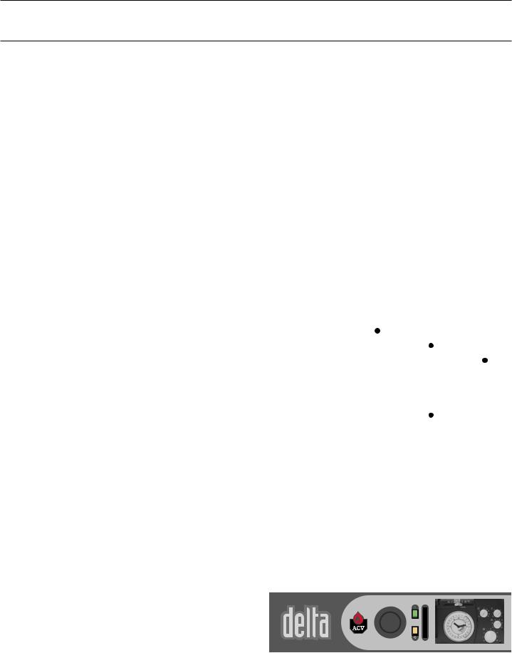
Control panel
1.Control thermostat (60/90°C)
2.Main switch
3.Summer/Winter switch
4.Thermometer
5.ACV Controller (opcional)
1 |
2 |
|
|
4 |
5 |
|||||
|
|
|
|
|
|
|
|
|
|
|
|
|
|
|
|
|
|
|
|
|
|
|
|
|
|
|
|
|
|
|
|
|
|
|
|
|
|
|
|
|
|
|
|
|
|
|
|
|
|
|
|
|
|
|
|
|
|
|
|
|
|
|
|
|
|
|
|
|
|
|
|
|
|
|
|
|
|
|
|
|
|
|
|
|
|
|
|
|
|
|
|
|
|
|
|
|
|
|
3
EN • 4

INTRODUCTION
Detachable casing cover (access to baffles)
Control panel
Manual reset high limit thermostat (103°C)
Bulb of the thermal reset high limit thermostat (95°C)
Detachable front panel
Control thermostat bulb
Burner chamber plate
Burner cover
Chimney reducing pipe
Polyurethane foam insulation
Outer body containing the primary water
Side casing
Base
Heating out |
Heating return |
Domestic hot water outlet |
Domestic cold water inlet |
|
|
Baffles |
Inner annular tank containing |
|
|
|
a domestic hot water |
Flue ways |
|
|
Combustion chamber |
Heating return |
|
|
Boiler drain cock |
|
EN • 5 |
INSTRUCTIONS
We recommend that you have your system serviced each year by a qualified engineer.
Starting the burner:
In normal operation the burner starts automatically if the temperature of the boiler is below setpoint.
Before carrying out any work on the boiler, isolate it from the electrical supply at the switch on the external control box.
Also move the main switch on the control panel to “OFF”.
PRESSURE IN THE HEATING SYSTEM
The Central Heating pressure must be minimum 1 bar and must be periodically checked by the end user.
Make sure that the appliance is powered off when filling the system. To do this, turn the on/off switch. For more information, please ask your installer when the system is delivered. A safety valve is provided underneath the appliance. If the system pressure exceeds 3 bars, this valve opens and drains the water from the system. In this case, please contact your installer.
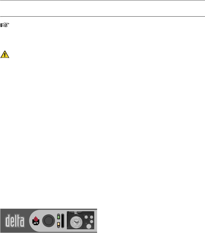
YOU SHOULD FAMILIARISE YOURSELF |
|
|
|
WITH THE CONTROL PANEL |
|
|
|
1 - Control thermostat |
|
|
|
If the boiler is being used to generate hot water only, the boiler |
The water escaping from the safety valve |
||
temperature can be set to between 60 and 90°C. If the boiler |
|||
is being used for hot water and heating, then the boiler’s control |
can be extremely hot and cause very |
||
thermostat should normally be set to 80°C to guarantee optimum |
|
serious burns. |
|
operating conditions. |
|
|
|
2 - Main switch |
|
|
|
This switch is used to start and stop the boiler |
|
|
|
3 - Summer/Winter switch |
|
|
|
Switches ON and OFF the heating pump. |
|
|
|
4 - Thermometer |
|
|
|
The thermometer shows the boiler temperature in the heating |
|
|
|
circuit. This temperature should not exceed 90°C. If it does, |
|
|
|
stop the boiler and check the settings on the thermostat. If the |
|
|
|
problem persists, contact your installer for advice. |
|
|
|
5 - ACV climatic controller (optional) |
|
|
|
Refer to the instructions supplied with the controller if you have |
|
|
|
this option. |
|
|
|
1 |
2 |
|
|
4 |
5 |
|||||
|
|
|
|
|
|
|
|
|
|
|
|
|
|
|
|
|
|
|
|
|
|
|
|
|
|
|
|
|
|
|
|
|
|
|
|
|
|
|
|
|
|
|
|
|
|
|
|
|
|
|
|
|
|
|
|
|
|
|
|
|
|
|
|
|
|
|
|
|
|
|
|
|
|
|
|
|
|
|
|
|
|
|
|
|
|
|
|
|
|
|
|
|
|
|
|
|
|
|
3
EN • 6
INSTRUCTIONS
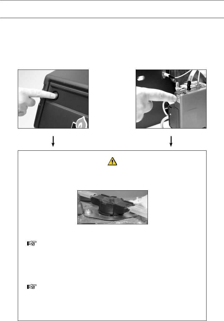
BURNER SHUTDOWN
If the oil burner is not working:
1.The burner indicator lamp lights.
2.Press the burner reset button on the burner. Now switch off the boiler for a few seconds at the main switch and then restart it.
If the gas burner is not working:
1.Remove the protective burner cover.
2.The reset button lamp is lit.
3.Press the reset button to start the burner. Now switch off the boiler for a few seconds at the main switch and then restart it.
If the oil or gas burner does not operate, isolate the boiler’s electrical supply at the switch on the external control box before removing the front panel of the casing, for press the manual reset high limit thermostat on the top of the boiler
Manual reset high limit thermostat
Wait until the boiler temperature drops to below 60°C, then refit the front panel of the casing.
If the problem persists, please contact your installer for advice.
Starting the burner.
In normal operation the burner starts automatically if the temperature of the boiler is below setpoint.
To ensure that your system operates correctly, please have it serviced annually by a qualified engineer; servicing should be done before the start of the heating season.
EN • 7
 Loading...