

ACV E-tech P 57, E-tech P 115, E-tech P144, E-tech P201, E-tech P 259 INSTALLATION OPERATING AND SERVICING INSTRUCTIONS
Page 1

57 - 115 - 144 - 201 - 259 [Tri phase]
Installation, operating and
servicing instructions
ENGLISHFRANCAISNEDERLANDSESPAÑOLITALIANODEUTSCH
664Y3500
EN • 1
Page 2

INDEX
WARNINGS 3
Who should read these instructions 3
Symbols 3
ENGLISHFRANCAISNEDERLANDSESPAÑOLITALIANODEUTSCH
Recommendations 3
Importants notes 3
INTRODUCTION 4
Description of the specifications 4
Casing 4
Heating body 4
Heating element
Connection 4
Control 4
Electrical protection 4
INSTRUCTIONS 5
User data 5
Setting up 5
Heating system pressure 5
Control panel legend 5
TECHNICAL CHARACTERISTICS 6
Electrical data 7
Power 7
Nominal current per phase 7
s 4
INSTALLATION : GENERAL 8
Dimensions 8
Installation room 8
Boiler room 8
Frost protection 8
Connecting to the system 8
INSTALLATION : HYDRAULIC 9
Heating connection 9
Heating connection + DWL 9
INSTALLATION : ELECTRIC SUPPLY 10
General safety rules 10
Important 10
Electrical connections 10
Sizing of supply wires 11
Power variation (kW) relative to voltage
Wiring diagrams 12
Power limitation 13
Powers wiring / Model : E-Tech P / 57 14
Powers wiring / Model : E-Tech P / 115 15
Powers wiring / Model : E-Tech P / 144 16
Powers wiring / Model : E-Tech P / 201 18
Powers wiring / Model : E-Tech P / 259 20
11
COMMISSIONING 22
Commissioning - Water 22
Commissioning - Electrical 22
Starting the boiler 22
22
MAINTENANCE 23
SPARE PARTS
664Y3500
EN • 2
See at the end of this manual
Page 3

WARNINGS
WHO SHOULD READ THESE INSTRUCTIONS
These instructions should be read by:
- the specifying engineer
- the installer
- the user
- the service engineer
SYMBOLS
Essential instruction for
the correct operation
of the installation.
Essential instruction for
the safety of persons
and the environment.
Danger of electrocution.
IMPORTANTS NOTES
ENGLISHFRANCAISNEDERLANDSESPAÑOLITALIANODEUTSCH
The manufacturer reserves the right to change the
technical characteristics and specification of its
products without notice.
The availability of certain versions and their accessories
can vary following the market.
Warning : Do not switch ON if there is a possibility that the
water in heater is frozen.
Danger of burns
RECOMMENDATIONS
• These instructions are an integral part of the equipment to
which they relate and must be handed to the user.
• The product must be installed and serviced by qualified
engineers in accordance with the regulations in force.
• The manufacturer declines all liability for any damage caused
as a result of incorrect installation or in the event of the use
of appliances or accessories that are not specified by the
manufacturer.
• Any failure to follow instructions relating to tests and test
procedures may result in personal injury or risks of pollution.
• It is important to switch the boiler off from the external
switching device before carrying out any work.
• There are no user parts inside the control panel.
• The installation must be in accordance with the current
standards.
664Y3500
EN • 3
Page 4
INTRODUCTION
DESCRIPTION OF THE SPECIFICATIONS:
This floor standing electric boiler is available in 5 models :
ENGLISHFRANCAISNEDERLANDSESPAÑOLITALIANODEUTSCH
- Model 57 with a power of 57,6 kW
- Model 115 with a power of 115,2 kW
- Model 144 with a power of 144 kW
- Model 201 with a power of 201,6 kW
- Model 259 with a power of 259,2 kW
The power circuit is supplied with 400 Volt tri phases without
neutral.
The control circuit is supplied with 230 Volt single phase.
CASING
The boiler is protected by a steel casing that has a red stove
enamelled finish.
HEATING BODY
The boiler heating body is constructed from mild steel with
welded joints. It is hydraulic tested at a pressure of 5,2 bar
(maximum working pressure = 4 bar).
HEATING ELEMENTS
Immersion heaters, constructed from stainless steel Incoloy 800
are mounted in the front of the boiler, provide the heating source
to the boiler.
CONNECTION
The boiler is suitable for connection to most heating and water
process systems, with a maximum working pressure of 4 bars and
a maximum temperature of 90°C. It can also be used in multiple
boiler installations allowing greater outputs to be achieved.
The boiler and connection glands are provided for the power
supply, the control supply and optional external controls.
CONTROL
The boiler is equipped with an electronic sequencing control that
constantly adapts the power required thanks to a four stage
modulation.
The boiler is commonly controlled by an external contact
(i.e. room thermostat). The maximum power can be limited to
25%, 50% or 75% by moving electrical bridges.
ELECTRICAL PROTECTION
The control circuit is protected by an internal 3 Amp MCB.
The power circuit is protected at its input by 3 power fuses.
Moreover, each contactor - supplying a pair of electric stars
(28,8kW) - is protected by an automatic thermal and magnetic
safety relay.
4
5
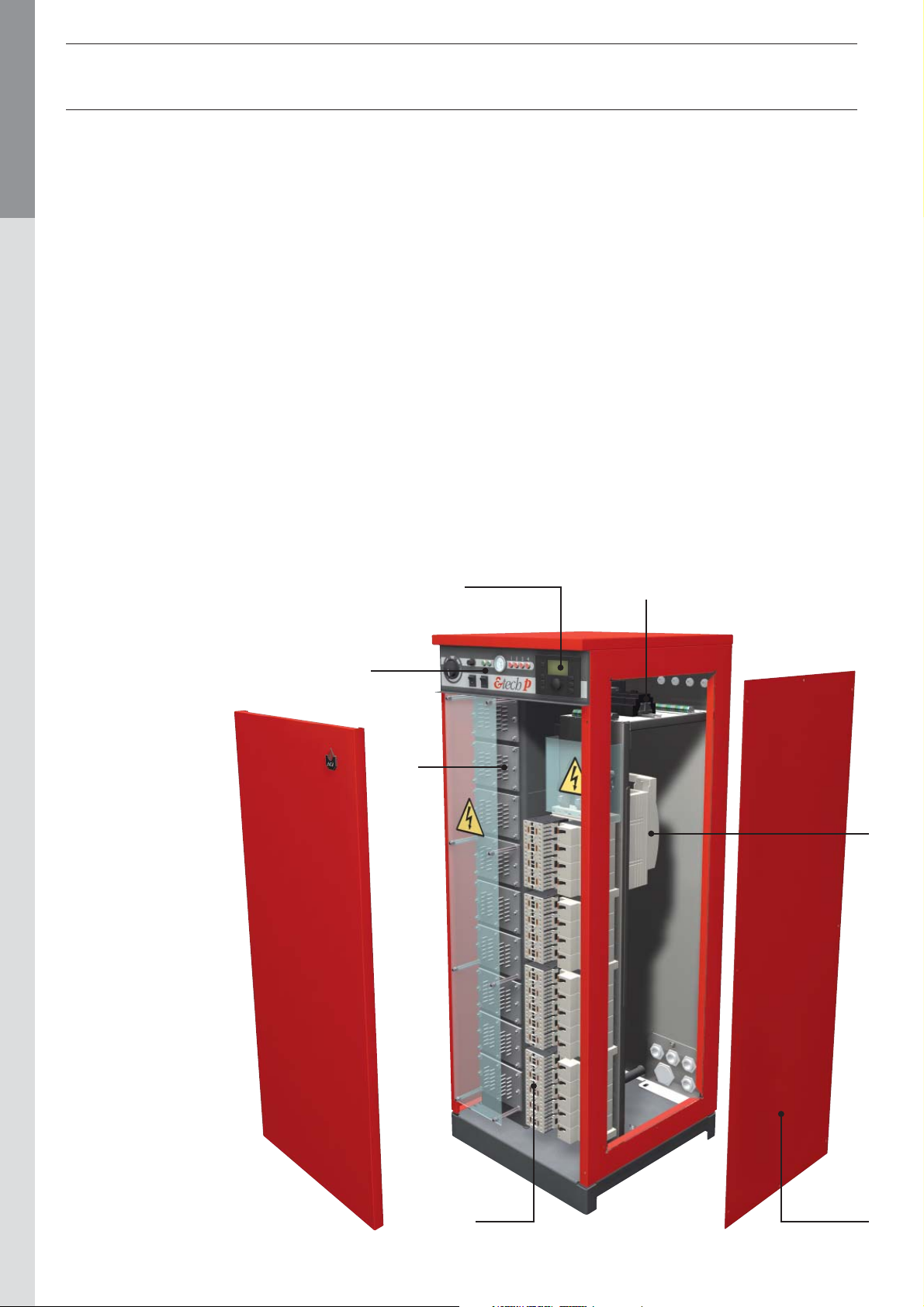
1. Control panel
2. Heating elements
3. Contactor and safety relays
4. Optional controller
5. Control circuit
6. Main fuses and power connections
7. Removable access panel
1
2
6
3
7
664Y3500
EN • 4
Page 5
INSTRUCTIONS
USER DATA
All user controls are situated on the front panel of the boiler,
there are no user controls inside the boiler casing.
The following instructions assume that the boiler has been
commissioned, and that the system is filled with water and has
been fully vented.
SETTING UP
• Before switching on any electrical supplies to the boiler ensure
that the combined temperature and pressure gauge reads at
least 1 bar and the control thermostat is set to the desired
temperature.
• If any other auxiliary controls are fitted e.g. programmer, room
thermostats, cylinder thermostats etc, consult appropriate
manufacturers’ instructions to switch these on.
• Switch the winter/summer switch to winter position.
• Switch on any local means of isolation to boiler.
Ensure all the jacket panels are secured before
switching on electrical supply from the external
isolator.
• Switch the boiler on using the ON/OFF switch (a test of the
lights is done).
• After a short period of time the boiler temperature should
start to rise, indicated on combined temperature and pressure
gauge. The modulation level is displayed on the front panel
by the stage indicator lights. If the boiler fails to operate, the
overheat safety thermostat should be checked.
Access to the thermostat reset button is obtained by unscrewing
(anti-clockwise) the domed button cover on the front panel
(a screwdriver is not required).The reset button can then
be seen - press the button, a click should be heard and the
button is reset. If no click was heard the device is not at fault
and further investigation is required by a suitably qualified
engineer.
• The external programmer can now be set to allow on/off
periods as desired. The ON/OFF switch should be left in the
ON position during normal use.
• As with most boilers and heating appliances the casing and
pipework can get hot during normal running so the boiler must
not be covered and the surrounding area must be kept clear.
HEATING SYSTEM PRESSURE
The CH pressure must be a minimum of 1 bar and must be
checked by the end user on a regular basis. If the pressure drops
under 0.5 bar, the integrated water pressure switch blocks the
appliance until the pressure in the system returns to a level
above 0.8 bar.
The installer must fit an external filling loop to the system.
For more information, please ask your installer when the system
is delivered.
A pressure safety valve is provided with the appliance. If the
system pressure exceeds 4 bars, this valve opens and drains
the water from the system. In this case, please contact your
installer.
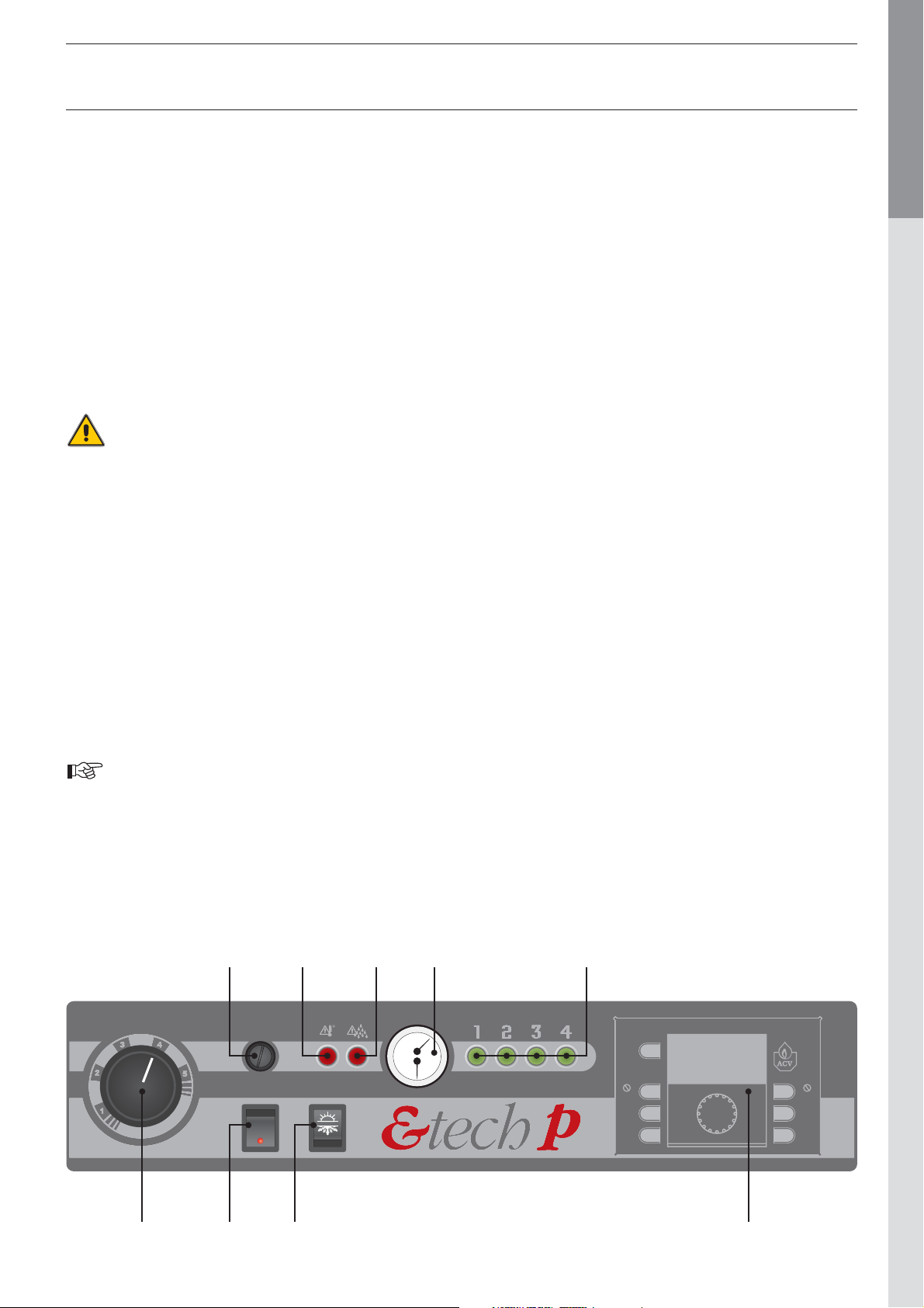
CONTROL PANEL LEGEND
1. Control thermostat :
1 = 25°C
2 = 40°C
3 = 55°C
4 = 70°C
5 = 85°C
2. ON/OFF switch
3. Summer/Winter switch
4. Manual reset high limit thermostat
5. Overheating warning light
6. Minimum water pressure warning light
7. Combined temperature and pressure gauge
ENGLISHFRANCAISNEDERLANDSESPAÑOLITALIANODEUTSCH
The power level indicator will automatically light on and
off during normal boiler operation, depending on boiler
temperature.
• If the boiler is not in regular daily use during cold periods, it is
recommended that it is fitted with a frost sensing thermostat
to prevent the system from freezing.
4 5 6 7 8
8. Power level indicators
9. Optional internal controller
664Y3500
1 2 3 9
EN • 5
Page 6

TECHNICAL CHARACTERISTICS
ENGLISHFRANCAISNEDERLANDSESPAÑOLITALIANODEUTSCH
Model 57 115 144 201 259
Power 57,6 kW 115,2 kW 144 kW 201.6 kW 259,2 kW
Nominal supply voltage
Power circuit 3 x 400 V 3 x 400 V 3 x 400 V 3 x 400 V 3 x 400 V
Control circuit
Heating element type 4 x 3 x 2.4 kW 4 x 3 x 2.4 kW 4 x 3 x 2.4 kW 4 x 3 x 2.4 kW 4 x 3 x 2.4 kW
Number of elements 24579
Ohmic value
of single resistance (2,4 kW)
Water capacity
(Litres)
Max. working pressure (bars) 44444
Min. working pressure (bars) 0.8 0.8 0.8 0.8 0.8
Max. working temperature
(°C)
Hydraulic pressure drop
(mbar) [ΔT = 10°C]
1 x 230 V
50/60 Hz
22,0 Ohm 22,0 Ohm 22,0 Ohm 22,0 Ohm 22,0 Ohm
60 60 60 102 102
90 90 90 90 90
20 79 123 20 33
1 x 230 V
50/60 Hz
1 x 230 V
50/60 Hz
1 x 230 V
50/60 Hz
1 x 230 V
50/60 Hz
Heating connection 2” [F] 2” [F] 2” [F] DN 100 (*) DN 100 (*)
Height (mm) 1495 1495 1495 1495 1495
Width (mm) 542 542 542 542 542
Depth (mm) 567 567 567 567 567
Weight empty (kg) 110 123 131 187 200
(*) DN100 fl anges to be welded
664Y3500
EN • 6
Page 7

TECHNICAL CHARACTERISTICS
POWER
Models
E-Tech P / 57 14,4 14,4 14,4 14,4 57,6
E-Tech P / 115 28,8 28,8 28,8 28,8 115,2
E-Tech P / 144 36,0 36,0 36,0 36,0 144,0
E-Tech P / 201 50,4 50,4 50,4 50,4 201,6
E-Tech P / 259 64,8 64,8 64,8 64,8 259,2
Models
Power (kW)
Stage 1
Stage 1
(A)
Power (kW)
Stage 2
NOMINAL CURRENT PER PHASE
Stage 2
(A)
Power (kW)
Stage 3
Stage 3
(A)
Power (kW)
Stage 4
Stage 4
(A)
Total Power
(kW)
Total current
per phase
(A)
ENGLISHFRANCAISNEDERLANDSESPAÑOLITALIANODEUTSCH
E-Tech P / 57 20,9 20,9 20,9 20,9 83,6
E-Tech P / 115 41,7 41,7 41,7 41,7 166,8
E-Tech P / 144 62,7 62,7 41,8 41,8 209
E-Tech P / 201 83,5 83,5 62,6 62,6 292,2
E-Tech P / 259 83,5 104,4 83,5 104,4 375,8
664Y3500
EN • 7
Page 8

DIMENSIONS
ENGLISHFRANCAISNEDERLANDSESPAÑOLITALIANODEUTSCH
Models
E-Tech P / 57 1495 567 550 183 542 125 2” [F]
E-Tech P / 115 1495 567 550 183 542 125 2” [F]
E-Tech P / 144 1495 567 550 183 542 125 2” [F]
E-Tech P / 201 1495 567 1100 183 542 125 DN 100
E-Tech P / 259 1495 567 1100 183 542 125 DN 100
INSTALLATION : GENERAL
A
mm
B
mm
C
mm
D
mm
B
E
mm
F
mm Heating connection
F
A
INSTALLATION ROOM
The minimum clearance around the appliance must comply
with the figure shown opposite.
BOILER ROOM
• Electric boilers must be installed in boiler rooms complying
with the relevant technical standards and applicable
regulations.
• The appliance should never be installed outdoors, because
it has not been designed for and is not equipped with
automatic defrosting systems.
• If possible, install the boiler above the ground level, to
reduce the risk of flooding the electrical components.
C
E
D
TOP VIEW
500 mm
FROST PROTECTION
The boiler is NOT fitted with frost protection. If the boiler is
being installed in a position where freezing could take place,
then a suitable external frost thermostat should be fitted.
CONNECTING TO THE SYSTEM
The boiler is designed to operate on a sealed system (ie. no
open vent or feed and expansion tank).
An adequate expansion vessel, sized accordingly must be
installed in the system.
664Y3500
500 mm
EN • 8
Page 9

INSTALLATION : HYDRAULIC
HEATING CONNECTION
HEATING CONNECTION + DHW (2 Circulating pumps)
The controller is factory programmed with DHW
priority.
To cancel the DHW priority, remove the black
wire from I7 and connect to I8 in the electronic
controller.
Adjustable temperature
0 - 90°C
1 = 25°C
2 = 40°C
3 = 55°C
4 = 70°C
5 = 85°C
1 = 25°C
2 = 40°C
3 = 55°C
4 = 70°C
5 = 85°C
ENGLISHFRANCAISNEDERLANDSESPAÑOLITALIANODEUTSCH
9 10
9 10
11 12
11 12
13 14
13 14
15 16
15 16
17 18
17 18
19 20
19 20
I
max
= 5A
Warning : Size the flow rate in hydraulic circuit to
insure a 10°C maximum ΔT.
BBkPkRWGWBkG
LNI1I2I3I4I5I6I7I8I9
V
Pk
I10
I11
I12
I7 = DHW priority I8 = DHW priority
Q1 Q3 Q5 Q6Q4 Q7 Q8Q2
0 - 90°C
BBkPkRWGWBkG
LNI1I2I3I4I5I6I7I8I9
Q1 Q3 Q5 Q6Q4 Q7 Q8Q2
V
Pk
I10
I11
I12
9 10
9 10
11 12
11 12
13 14
13 14
15 16
15 16
17 18
17 18
19 20
19 20
664Y3500
EN • 9
Page 10

INSTALLATION : ELECTRIC SUPPLY
WARNING !!!
Size the flow rate in the hydraulic circuit to ensure a 10°C
ENGLISHFRANCAISNEDERLANDSESPAÑOLITALIANODEUTSCH
maximum ΔT.
GENERAL SAFETY RULES
• The boiler must be installed by a competent person or
registered company.
• After the installation work, the installer must issue a statement
of compliance, declaring that the installation has been carried
out in a workmanlike manner, as defined for by the applicable
regulations.
• Make sure that the wiring system and the power input lines are
designed and installed by skilled engineers in compliance with
the applicable regulations.
IMPORTANT
• As far as the power input to the boiler is concerned, the
installation must comply with IEC 364 standards and other
provisions concerning installation conditions.
• The default electrical safeties integrated in the boiler protect
the internal parts of the boiler. Electrical safeties, including
isolators must be installed in an external box.
• For protection against electrical hazard, it is always
recommended to install a differential cut-out device (Ground
Fault Isolator) on the power supply circuit, upstream of the
boiler.
• For protection against overheating, it is advisable to place an
external positive safety power cut-out, controlled by the boiler
safety thermostat.
8. Remount the bottom protection and close the power
connections box.
1
2
1
ELECTRICAL CONNECTIONS
1. Remove the right panel cover and the top panel
2. Connect the electrical supply to the control circuit and all
accessories (room thermostat, …)
3. Pass the power cabels thought the cable glands located in
the rear panel.
Models
E-Tech P / 57 1 x PG 36 4 x PG 21
E-Tech P / 115 1 x PG 48 4 x PG 21
E-Tech P / 144 1 x PG 48 4 x PG 21
E-Tech P / 201 4 x PG 29 1 x PG 48
E-Tech P / 259 4 x PG 29 1 x PG 48
(*) Optionally, the installer has the possibility to remove the standard cable
glands and install the optional cable glands (not supplied) on site.
4. Connect the earth using a ring terminal.
5. Open the power connections box.
6. Remove the bottom protection.
7. Connect the power wires to the main connections using ring
terminals.
(*) a transormation kit is supplied with the boiler in order to
connect the power wires using compression terminals (see
detailled instructions sheet in the kit).
Standard
cable gland
Optional
cable gland (*)
34
5
664Y3500
Optional connection
6
EN • 10
Page 11

INSTALLATION : ELECTRIC SUPPLY
SIZING OF SUPPLY WIRES
The supply wires are sized depending of the type and current of
the MCB. The MCB last is sized depending of the nominal current
of the boiler. The admissible current of the supply wires depends
of the ambient temperature, the section, the length and the
insulation of the wires, the wires ducts, the mounting and the
environment.
The following values are given for information for an ambient
temperature of 25°C and a maximum length of 5 meters. In all
the circumstances, the installation must be in accordance with
the current IEE wiring regulations.
Diameter
2
mm
1,5 16
2,5 25
4,6 36
10 47
16 65
25 87
35 115
50 143
Current
Amp
POWER VARIATION (kW) RELATIVE TO VOLTAGE
ENGLISHFRANCAISNEDERLANDSESPAÑOLITALIANODEUTSCH
Models 3 x 380 V 3 x 400 V 3 x 415 V 3 x 440 V
E-Tech P / 57 51,4 57,6 62,0 70
E-Tech P / 115 103,8 115,2 124,0 139
E-Tech P / 144 130,0 144,0 155,0 174
E-Tech P / 201 181,4 201,6 217,0 244
E-Tech P / 259 233,7 259,2 279,0 314
70 178
95 220
120 265
150 310
185 355
240 480
For higher temperatures, the supply wire diameter should be
adapter according the derating factor.
T ambient
°C
25 100
30 92
35 85
40 75
45 65
50 53
Current derating
%
664Y3500
55 38
EN • 11
Page 12

WIRING DIAGRAMS
ENGLISHFRANCAISNEDERLANDSESPAÑOLITALIANODEUTSCH
INSTALLATION : ELECTRIC SUPPLY
Bk Bk
Br Br Br
1
Y/Gr
2
Y/Gr
Y/Gr
3 Amp
5
15
18
MCB
Bk
A
Bk
B
2
G
C
Or
1
t
Bk
4
BkBk
C
1
Pk
C
RR
2
P
Or
7
Bk W
D
Pk V
E
C
11 12
9 10
1
2
t
2625
B
Bk
L
PkRW
G
N
I1I2I3I4I5I6I7I8I9
Bk
Bk
27 29
WW
V
28 30
W
Bk
G
Pk
I10
I11
I12
F
G
Q1 Q3 Q5 Q6Q4 Q7 Q8Q2
Pk
R R
R
V
R
Bk
R
R
Bk
Bk
BBB
3
B : Blue
Bk : Black
Br : Brown
G : Grey
Or : Orange
Pk : Pink
R : Red
V : Violet
W : White
Y : Yellow
Y/Gr : Yellow/Green
B
8
B
6
B
B
A ON/OFF switch
B Manual reset high limit thermostat
C Water pressure switch
D Summer / Winter switch
E Boiler thermostat 0 - 90°C
F Alarm indicator
G Electronic controller
WW
Pk
Pk
23
24
B
B
K1
B
B
BV
B
BW WK3BBB
K2
Bk
K4
VV
13
16
19
14
18
B
20
B
BR
R
21
22
BOrOr
BOr
I1 High temperature
I2 Water pressure
I3 Common alarm signal
I4 Boiler demand
I5 Central heating demand
I6 DHW demand
I7 DHW priority
I8 Without DHW priority
I9 SW1 (power limitation)
I10 SW2 (power limitation)
Q1 K1
Q2 K2
Q3 K3
Q4 K4
Q5 Heating pump
Q6 DHW pump
Q7 Water pressure warning light
Q8 High temperature warning light
664Y3500
EN • 12
Page 13

INSTALLATION : ELECTRIC SUPPLY
POWER LIMITATION :
The maximum power of the boiler can be limited from 25 to 100%
by acting on the SW1, SW2 electrical bridges as mentioned in
the table below.
Power 25% 50% 75% 100%
SW1 0 1 0 1
SW2 0 0 1 1
25% = Only 1 stage
50% = Only 1 and 2 stages
75% = Only 1 to 3 stages
100% = All stages
Any change to the power limitation will alter the
current once the boiler has switched to stand-by (busy
signal is OFF). The external management system can
then open the ON/OFF link.
ENGLISHFRANCAISNEDERLANDSESPAÑOLITALIANODEUTSCH
CONTROL CIRCUIT TERMINAL
230 V OUT (PE)
230 V OUT (N)
Safety relay (N)
Central heating demand (OUT)
Central heating demand (IN)
DHW demand (IN)
DHW demand (OUT)
Central heating pump 230 V
Central heating pump (N)
Central heating pump (PE)
DHW pump 230 V
DHW pump (PE)
DHW pump (N)
Water pressure alarm 230 V
Water pressure alarm (N)
Safety thermostat alarm 230 V
Safety thermostat alarm (N)
Heating ON signal (busy) 230 V
Heating ON signal (busy) (N)
ON / OFF switch
ON / OFF switch
Heating power SW1
Heating power SW1
Heating power SW2
Heating power SW2
Power L
Power PE
Power N
230 V OUT (L)
Safety relay (L)
21 3 5 15 174 7 9 10 11 12 13 16 19 21 23 25 26 27 28 29 306 8 14 18 20 22 24
664Y3500
EN • 13
Page 14

INSTALLATION : ELECTRIC SUPPLY
POWER WIRING / MODEL : E-TECH P / 57
ENGLISHFRANCAISNEDERLANDSESPAÑOLITALIANODEUTSCH
2
35 mm
F-100A
L1L2L3
20 x 5 mm
Q4 - 1
K4 - 1
K4 - 1
Stage 4
K3 - 1
Stage 3
K2 - 1
Stage 2
K1 - 1
Stage 1
T1
T1
T2
T3
T1
T2
T3
T1
T2
T3
T1
T2
T3
K4 - 1
T2
Stage 4
T3
T1
K3 - 1
T2
Stage 3
T3
T1
K2 - 1
T2
Stage 2
T3
T1
K1 - 1
T2
Stage 1
T3
BF09
L1
A1A2 A1A2 A1A2 A1
L2
L3
A2
NO
BF09
L1
L2
L3
NO
BF09
L1
L2
L3
NO
BF09
L1
L2
L3
NO
SMB 52
23
25
20
SMB 52
23
25
20
SMB 52
23
25
20
SMB 52
23
25
20
K4 - 1
K3 - 1
K2 - 1
K1 - 1
Q3 - 1
K3 - 1
Q2 - 1
K2 - 1
664Y3500
Q1 - 1
K1 - 1
EN • 14
Page 15

INSTALLATION : ELECTRIC SUPPLY
POWER WIRING / MODEL : E-TECH P / 115
2
95 mm
ENGLISHFRANCAISNEDERLANDSESPAÑOLITALIANODEUTSCH
L1L2L3
F-200A
20 x 5 mm
Q4 - 2
K4 - 2
Q3 - 2
K3 - 2
Q4 - 1
K4 - 1
Q3 - 1
K3 - 1
K4 - 2
Stage 4
K4 - 1
Stage 4
K3 - 2
Stage 3
K3 - 1
Stage 3
K2 - 2
Stage 2
K2 - 1
Stage 2
K1 - 2
Stage 1
K1 - 1
Stage 1
T1
T1
T2
T3
T1
T2
T3
T1
T2
T3
T1
T2
T3
T1
T2
T3
T1
T2
T3
T1
T2
T3
T1
T2
T3
K4 - 2
T2
Stage 4
T3
T1
K4 - 1
T2
Stage 4
T3
T1
K3 - 2
T2
Stage 3
T3
T1
K3 - 1
T2
Stage 3
T3
T1
K2 - 2
T2
Stage 2
T3
T1
K2 - 1
T2
Stage 2
T3
T1
K1 - 2
T2
Stage 1
T3
T1
K1 - 1
T2
Stage 1
T3
BF09
L1
A1A2 A1A2 A1A2 A1
L2
L3
A2
NO
BF09
L1
L2
L3
NO
BF09
L1
L2
L3
NO
BF09
L1
L2
L3
NO
BF09
L1
A1A2 A1A2 A1A2 A1
L2
L3
A2
NO
BF09
L1
L2
L3
NO
BF09
L1
L2
L3
NO
BF09
L1
L2
L3
NO
SMB 52
23
25
20
SMB 52
23
25
20
SMB 52
23
25
20
SMB 52
23
25
20
SMB 52
23
25
20
SMB 52
23
25
20
SMB 52
23
25
20
SMB 52
23
25
20
K4 - 2
K4 - 1
K3 - 2
K3 - 1
K2 - 2
K2 - 1
K1 - 2
K1 - 1
664Y3500
Q2 - 2
K2 - 2
Q1 - 2
K1 - 2
Q2 - 1
K2 - 1
Q1 - 1
K1 - 1
EN • 15
Page 16

INSTALLATION : ELECTRIC SUPPLY
POWER WIRING / MODEL : E-TECH P / 144
ENGLISHFRANCAISNEDERLANDSESPAÑOLITALIANODEUTSCH
2
120 mm
F-250A
L1L2L3
20 x 5 mm
Q4 - 2
K4 - 2
Q3 - 2
K3 - 2
Q4 - 1
K4 - 1
Q3 - 1
K3 - 1
664Y3500
Q2 - 3
K2 - 3
Q1 - 3
K1 - 3
Q2 - 2
K2 - 2
Q1 - 2
K1 - 2
EN • 16
Q2 - 1
K2 - 1
Q1 - 1
K1 - 1
Page 17

INSTALLATION : ELECTRIC SUPPLY
POWER WIRING / MODEL : E-TECH P / 144
T1
T1
K4 - 2
Stage 4
K4 - 1
Stage 4
K3 - 2
Stage 3
K3 - 1
Stage 3
K2 - 3
Stage 2
K2 - 2
Stage 2
K2 - 1
Stage 2
K1 - 3
Stage 1
K1 - 2
Stage 1
K1 - 1
Stage 1
T2
T3
T1
T2
T3
T1
T2
T3
T1
T2
T3
T1
T2
T3
T1
T2
T3
T1
T2
T3
T1
T2
T3
T1
T2
T3
T1
T2
T3
K4 - 2
T2
Stage 4
T3
T1
K4 - 1
T2
Stage 4
T3
T1
K3 - 2
T2
Stage 3
T3
T1
K3 - 1
T2
Stage 3
T3
T1
K2 - 3
T2
Stage 2
T3
T1
K2 - 2
T2
Stage 2
T3
T1
K2 - 1
T2
Stage 2
T3
T1
K1 - 3
T2
Stage 1
T3
T1
K1 - 2
T2
Stage 1
T3
T1
K1 - 1
T2
Stage 1
T3
BF09
L1
A1A2 A1A2 A1A2 A1
L2
L3
A2
NO
BF09
L1
L2
L3
NO
BF09
L1
L2
L3
NO
BF09
L1
L2
L3
NO
BF09
L1
A1A2 A1A2 A1A2 A1
L2
L3
A2
NO
BF09
L1
L2
L3
A2 A1
NO
BF09
L1
L2
L3
A2 A1
NO
BF09
L1
L2
L3
NO
BF09
L1
L2
L3
NO
BF09
L1
L2
L3
NO
SMB 52
23
25
20
SMB 52
23
25
20
SMB 52
23
25
20
SMB 52
23
25
20
SMB 52
23
25
20
SMB 52
23
25
20
SMB 52
23
25
20
SMB 52
23
25
20
SMB 52
23
25
20
SMB 52
23
25
20
ENGLISHFRANCAISNEDERLANDSESPAÑOLITALIANODEUTSCH
K4 - 2
K4 - 1
K3 - 2
K3 - 1
K2 - 3
K2 - 2
K2 - 1
K1 - 3
K1 - 2
K1 - 1
664Y3500
EN • 17
Page 18

INSTALLATION : ELECTRIC SUPPLY
POWER WIRING / MODEL : E-TECH P / 201
ENGLISHFRANCAISNEDERLANDSESPAÑOLITALIANODEUTSCH
2
185 mm
F-315A
L1L2L3
30 x 5 mm
Q4 - 3
K4 - 3
Q3 - 3
K3 - 3
Q4 - 2
K4 - 2
Q3 - 2
K3 - 2
Q4 - 1
K4 - 1
Q3 - 1
K3 - 1
664Y3500
Q2 - 4
K2 - 4
Q1 - 4
K1 - 4
Q2 - 3
K2 - 3
Q1 - 3
K1 - 3
Q2 - 2
K2 - 2
Q1 - 2
K1 - 2
EN • 18
Q2 - 1
K2 - 1
Q1 - 1
K1 - 1
Page 19

INSTALLATION : ELECTRIC SUPPLY
POWER WIRING / MODEL : E-TECH P / 201
ENGLISHFRANCAISNEDERLANDSESPAÑOLITALIANODEUTSCH
K4 - 3
Stage 4
K4 - 2
Stage 4
K4 - 1
Stage 4
K3 - 3
Stage 3
K3 - 2
Stage 3
K3 - 1
Stage 3
K2 - 4
Stage 2
K2 - 3
Stage 2
K2 - 2
Stage 2
K2 - 1
Stage 2
K1 - 4
Stage 1
K1 - 3
Stage 1
BF09
T1
T1
T2
T3
T1
T2
T3
T1
T2
T3
T1
T2
T3
T1
T2
T3
T1
T2
T3
T1
T2
T3
T1
T2
T3
T1
T2
T3
T1
T2
T3
T1
T2
T3
T1
T2
T3
K4 - 3
T2
Stage 4
T3
T1
K4 - 2
T2
Stage 4
T3
T1
K4 - 1
T2
Stage 4
T3
T1
K3 - 3
T2
Stage 3
T3
T1
K3 - 2
T2
Stage 3
T3
T1
K3 - 1
T2
Stage 3
T3
T1
K2 - 4
T2
Stage 2
T3
T1
K2 - 3
T2
Stage 2
T3
T1
K2 - 2
T2
Stage 2
T3
T1
K2 - 1
T2
Stage 2
T3
T1
K1 - 4
T2
Stage 1
T3
T1
K1 - 3
T2
Stage 1
T3
L1
L2
L3
A2 A1
NO
BF09
L1
L2
L3
A2 A1
NO
BF09
L1
L2
L3
A2 A1A2 A1A2 A1
NO
BF09
L1
L2
L3
NO
BF09
L1
L2
L3
NO
BF09
L1
L2
L3
A2 A1
NO
BF09
L1
L2
L3
A2 A1A2 A1A2 A1
NO
BF09
L1
L2
L3
NO
BF09
L1
L2
L3
NO
BF09
L1
L2
L3
A2 A1
NO
BF09
L1
L2
L3
A2 A1
NO
BF09
L1
L2
L3
A2 A1A2 A1
NO
BF09
L1
L2
L3
A2 A1
NO
BF09
L1
L2
L3
NO
SMB 52
23
25
20
SMB 52
23
25
20
SMB 52
23
25
20
SMB 52
23
25
20
SMB 52
23
25
20
SMB 52
23
25
20
SMB 52
23
25
20
SMB 52
23
25
20
SMB 52
23
25
20
SMB 52
23
25
20
SMB 52
23
25
20
SMB 52
23
25
20
SMB 52
23
25
20
SMB 52
23
25
20
K4 - 3
K4 - 2
K4 - 1
K3 - 3
K3 - 2
K3 - 1
K2 - 4
K2 - 3
K2 - 2
K2 - 1
K1 - 4
K1 - 3
K1 - 2
K1 - 1
K1 - 2
Stage 1
K1 - 1
Stage 1
664Y3500
T1
T1
T2
T3
T1
T2
T3
K1 - 2
T2
Stage 1
T3
T1
K1 - 1
T2
Stage 1
T3
EN • 19
Page 20

INSTALLATION : ELECTRIC SUPPLY
POWER WIRING / MODEL : E-TECH P / 259
ENGLISHFRANCAISNEDERLANDSESPAÑOLITALIANODEUTSCH
2
240 mm
F-400A
L1L2L3
30 x 5 mm
Q4 - 5
K4 - 5
Q3 - 4
K3 - 4
Q4 - 4
K4 - 4
Q3 - 3
K3 - 3
Q4 - 3
K4 - 3
Q3 - 2
K3 - 2
Q4 - 2
K4 - 2
Q3 - 1
K3 - 1
Q4 - 1
K4 - 1
664Y3500
Q2 - 5
K2 - 5
Q1 - 4
K1 - 4
Q2 - 4
K2 - 4
Q1 - 3
K1 - 3
Q2 - 3
K2 - 3
Q1 - 2
K1 - 2
EN • 20
Q2 - 2
K2 - 2
Q1 - 1
K1 - 1
Q2 - 1
K2 - 1
Page 21

INSTALLATION : ELECTRIC SUPPLY
POWER WIRING / MODEL : E-TECH P / 259
T1
T1
K4 - 5
Stage 4
K4 - 4
Stage 4
K4 - 3
Stage 4
K4 - 2
Stage 4
T2
T3
T1
T2
T3
T1
T2
T3
T1
T2
T3
K4 - 5
T2
Stage 4
T3
T1
K4 - 4
T2
Stage 4
T3
T1
K4 - 3
T2
Stage 4
T3
T1
K4 - 2
T2
Stage 4
T3
ENGLISHFRANCAISNEDERLANDSESPAÑOLITALIANODEUTSCH
K4 - 1
Stage 4
K3 - 4
Stage 3
K3 - 3
Stage 3
K3 - 2
Stage 3
K3 - 1
Stage 3
K2 - 5
Stage 2
K2 - 4
Stage 2
K2 - 3
Stage 2
K2 - 2
Stage 2
K2 - 1
Stage 2
K1 - 4
Stage 1
K1 - 3
Stage 1
K1 - 2
Stage 1
K1 - 1
Stage 1
BF09
T1
T1
T2
T3
T1
T2
T3
T1
T2
T3
T1
T2
T3
T1
T2
T3
T1
T2
T3
T1
T2
T3
T1
T2
T3
T1
T2
T3
T1
T2
T3
T1
T2
T3
T1
T2
T3
T1
T2
T3
T1
T2
T3
K4 - 1
T2
Stage 4
T3
T1
K3 - 4
T2
Stage 3
T3
T1
K3 - 3
T2
Stage 3
T3
T1
K3 - 2
T2
Stage 3
T3
T1
K3 - 1
T2
Stage 3
T3
T1
K2 - 5
T2
Stage 2
T3
T1
K2 - 4
T2
Stage 2
T3
T1
K2 - 3
T2
Stage 2
T3
T1
K2 - 2
T2
Stage 2
T3
T1
K2 - 1
T2
Stage 2
T3
T1
K1 - 4
T2
Stage 1
T3
T1
K1 - 3
T2
Stage 1
T3
T1
K1 - 2
T2
Stage 1
T3
T1
K1 - 1
T2
Stage 1
T3
L1
L2
L3
A2 A1
NO
BF09
L1
L2
L3
A2 A1
NO
BF09
L1
L2
L3
A2 A1A2 A1A2 A1
NO
BF09
L1
L2
L3
NO
BF09
L1
L2
L3
NO
BF09
L1
L2
L3
A2 A1
NO
BF09
L1
L2
L3
A2 A1A2 A1A2 A1
NO
BF09
L1
L2
L3
NO
BF09
L1
L2
L3
NO
BF09
L1
L2
L3
A2 A1
NO
BF09
L1
L2
L3
A2 A1
NO
BF09
L1
L2
L3
A2 A1A2 A1A2 A1
NO
BF09
L1
L2
L3
NO
BF09
L1
L2
L3
NO
BF09
L1
L2
L3
A2 A1
NO
BF09
L1
L2
L3
A2 A1A2 A1A2 A1
NO
BF09
L1
L2
L3
NO
BF09
L1
L2
L3
NO
SMB 52
23
25
20
SMB 52
23
25
20
SMB 52
23
25
20
SMB 52
23
25
20
SMB 52
23
25
20
SMB 52
23
25
20
SMB 52
23
25
20
SMB 52
23
25
20
SMB 52
23
25
20
SMB 52
23
25
20
SMB 52
23
25
20
SMB 52
23
25
20
SMB 52
23
25
20
SMB 52
23
25
20
SMB 52
23
25
20
SMB 52
23
25
20
SMB 52
23
25
20
SMB 52
23
25
20
K4 - 5
K4 - 4
K4 - 3
K4 - 2
K4 - 1
K3 - 4
K3 - 3
K3 - 2
K3 - 1
K2 - 5
K2 - 4
K2 - 3
K2 - 2
K2 - 1
K1 - 4
K1 - 3
K1 - 2
K1 - 1
664Y3500
EN • 21
Page 22

COMMISSIONING
COMMISSIONING - WATER
1. The system must be thoroughly flushed prior to connection
ENGLISHFRANCAISNEDERLANDSESPAÑOLITALIANODEUTSCH
of the boiler. The system water should be treated to prevent
general corrosion and deposition of scale or sludge in the
boiler. If installing the boiler onto an existing system, ACV
recommend that an approved system cleaner is used.
2. Fill and pressurise the boiler and system to 1.5 bar, making
sure to vent the boiler via the automatic air vent on top of the
boiler. Note that the black dust cap on the air vent should be
left loose to allow the auto vent to function.
3. Check for leaks.
COMMISSIONING - ELECTRICAL
The Electrical installation supplying this boiler must conform to
the current IEE Regulations.
1. Remove the front and the right-handside. Check all electrical
connections for tightness.
2. Ensure all internal relays, contactors etc are secure on the
DIN rails.
3. Set panel control main switches to off.
4. Set internal MCB to off position.
5. Set the control thermostat to desired temperature.
STARTING THE BOILER
1. Switch on internal MCB
2. Fit and secure all panels
3. Switch on local isolator to boiler
4. Turn the boiler on using the ON/OFF switch
5. The first stage energises as indicated by the panel light.
The temperature will now rise as indicated by the combined
temperature and pressure gauge. As long as the control
thermostat set-point is not reached, the next stage is
energised every 2 minutes until all the stages are energised.
When the control thermostat set-point is reached, the last
stage is de-ernergized every 30 seconds until all the stages
are de-energized.
Once these procedures have been followed the system can be
left to operate normally.
After one week of operation all electrical connections
should be re-checked. The fixing nuts must of the
heating elements must be re-tightened at the nominal
torque of 10 Nm following the tightening sequence
mentioned in maintenance section.
664Y3500
EN • 22
Page 23

MAINTENANCE
MAINTENANCE
For safety reasons it is recommended that the boiler is serviced
annually and that servicing is carried out by a qualified service
engineer.
Before carrying out any work on the system
ensure that the boiler is cool and all
electrical supplies are isolated.
1. After removing the front and the right panels, Undertake
a visual inspection of the boiler checking for signs of water
leakage from gaskets, and the components on top of the
boiler.
2. Undertake a visual inspection of all wiring in the boiler casing
checking for signs of overheating or burning.
3. Check all push-on electrical connectors for tightness and
good connection to the relative components.
4. Using a correct fitting screwdriver check all electrical
terminals on DIN rails and on all components for tightness.
5. Re-tight the fixing nuts of the heating element at nominal
torque of 10 Nm following the tightening sequence.
6. Check all individual circuit breakers are in the normal
position. If some fuses have tripped, check the wiring and the
resistance before reactivating them.
7. Replacement of the heating element (if required).
7. Replacement of the main fuses (if required)
ENGLISHFRANCAISNEDERLANDSESPAÑOLITALIANODEUTSCH
Models Fuses ACV code
E-Tech P / 57 100 A 5476C006
E-Tech P / 115 200 A 5476C007
E-Tech P / 144 250 A 5476C008
E-Tech P / 201 315 A 5476C009
E-Tech P / 259 400 A 5476C010
1
2
5476D003
557A0088
Ohmic value : 22 Ω
1
5 7
3 4
8 6
2
torque = 10 Nm
8. Fit the right-hand panel and the boiler front cover and refit
screws.
9. Switch ON the electrical supply and following the procedures
described in the commissioning section.
Before opening any cover and/or caring
and any work on the system, ensure that
the system is electrically disconnected
from the power supply.
664Y3500
Please follow the tightening sequence
EN • 23
Page 24

ENGLISHFRANCAISNEDERLANDSESPAÑOLITALIANODEUTSCH
664Y3500
EN • 24
 Loading...