

ACV delta performance ventouse SV, delta performance ventouse MV INSTALLATION OPERATING AND SERVICING INSTRUCTIONS
Page 1
Installation, Operating and
Servicing Instructions
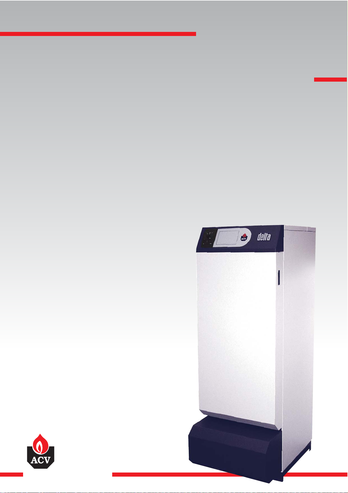
delta
excellence in hot water
delta
performance
performance
ventouse SV/MV
24/09/2004 - 66401501
Page 2

Page 3

1
INDEX
INTRODUCTION 2
Who should read these instructions 2
Symbols 2
Applicable standards 2
Important notes 2
DESCRIPTION 3
General description 3
Operating principle 3
Design characteristics 3
Boiler views and key to parts 4
TECHNICAL CHARACTERISTICS 5
General 5
Operating condition limits 5
Dimensions 5
Hot water output data 5
General characteristics 5
INSTALLATION 6
Boiler room 6
Chimney connections 6
Heating connection 8
Hot water connection 8
Control kit 9
Connection to the gas supply 9
Electrical connections 10
BURNER CHARACTERISTICS 12
Description of the burner 12
Operating principle of the burner 14
Control parameters 15 Gas categories 15
Burner dismantling procedure 16
Setting procedure in the event of fan
replacement 16 Procedure for setting the % of CO2 16
Electrode distance and gap 17
Burner maintenance 17
Fault table 18
Table of corrective measures 19
COMMISSIONING 20
Filling the hot water and heating circuits 20
Using the boiler for the first time 20
MAINTENANCE 20
Recommendation 20
Boiler maintenance 20
Safety equipment maintenance 20
Draining the boiler 20
USER GUIDE 21
Use of the boiler 21
Setting the burner to safety mode 22
SPARE PARTS 23
SERVICE RECORD 29
Details of the installation 29
Service engineer's report 29
Page 4
2
WHO SHOULD READ THESE INSTRUCTIONS
These instructions should be read by:
- the specifying engineer
- the installer
- the user
- the service engineer
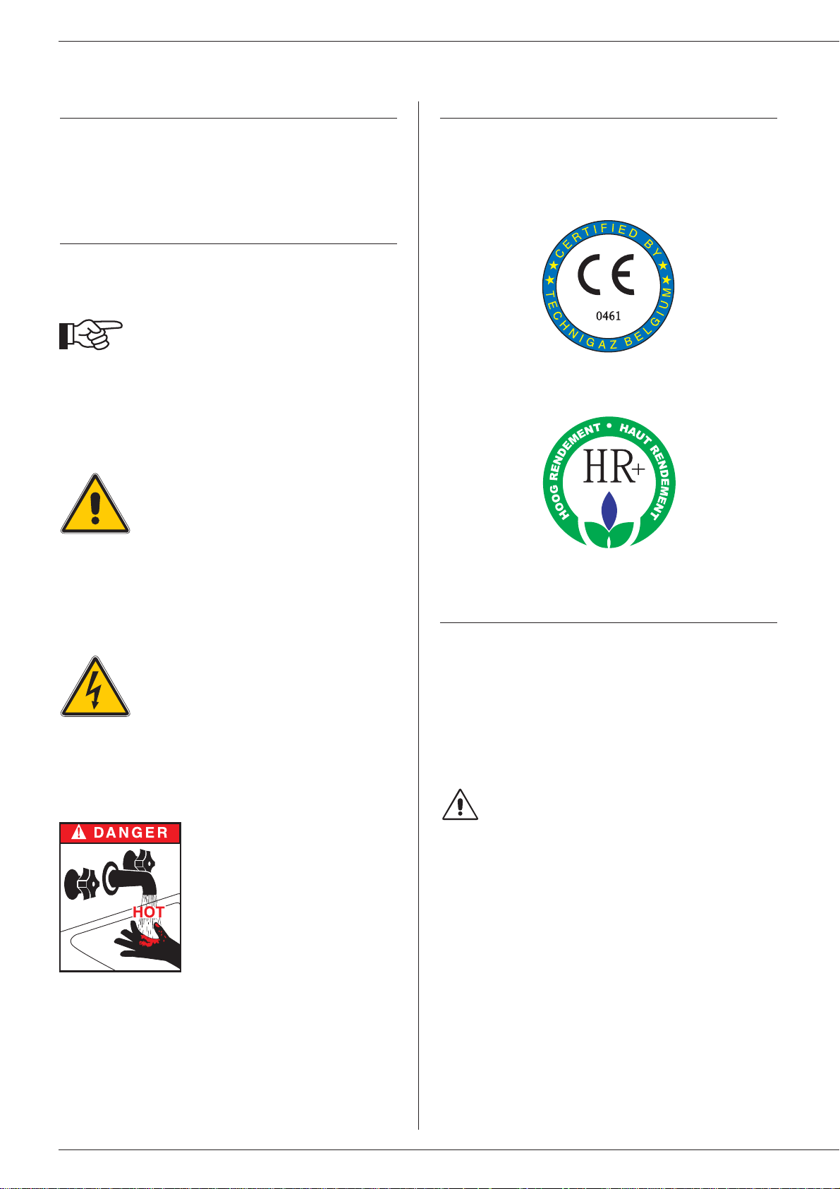
SYMBOLS
The following symbols are used in these instructions:
APPLICABLE STANDARDS
The products described in this document have been certified at
European level (European Directives 92/42/EEC “Efficiency”,
90/396/EEC “Gas Appliance”). They have also be awarded the
Belgian label “HR+”.
IMPORTANT NOTES
These instructions are an integral part of the equipment to which
they relate and must be handed to the user.
The product must be installed and serviced by qualified engineers in
accordance with the regulations in force.
ACV declines all liability for any damage caused as a result of
incorrect installation or in the event of the use of appliances or
accessories that are not specified by ACV.
Failure to follow the instructions describing test
operations and procedures may cause injury to
persons or a risk of environmental pollution.
N.B.:
ACV reserves the right to change the technical characteristics and
specification of its products without notice.
INTRODUCTION
Essential instruction for the correct operation of
the installation.
Burning hazard.
Electric shock hazard.
Essential instruction for the safety of persons and
the environment.
Page 5

3
GENERAL DESCRIPTION
• Combined boiler and water heater (heating and domestic hot water).
•Hot water generated by the TANK-IN-TANK indirect storage
system.
• Equipment required: a water connection kit for the heating circuit
supply (optional).
• The control panel contains a main switch, a control thermostat for
the SV model or potentiometer for the MV model, a thermometer,
a Summer/Winter switch and a knockout for the built-in ACV
control system
(optional).
• Delta Performance models SV and MV can be connected as a
balanced flue system using a type C concentric or parallel
chimney adapter
xx, or connected directly to the chimney with a
type B23 chimney adapter.
• Delta Performance models SV 35 and 50 have fixed outputs of 35
and 50 kW respectively and are fitted with the ACV BG 2000-SV
gas burner.
• Delta Performance models MV 35 and 50 have modulating
outputs of 10 to 35 kW and 15 to 50 kW respectively, and are
fitted with the ACV BG 2000-MV gas burner.
OPERATING PRINCIPLE
The “Tank-in-Tank” concept
The Delta Performance ventouse range of boilers differs from
conventional hot water heaters in that it features a ring-shaped tank
which is immersed in the primary water, and which is itself contained
in the outer body. The thermostat/potentiometer activates the burner
when the heating system or the hot water circuit calls for heat.The
combustion gases quickly heat up the primary water and set up a
natural circulation around the tank.
Indirect hot water heating
This circulation causes heat to be exchanged between the primary
water and the domestic water; heat is exchanged across the entire
surface of the tank.Corrugations on the inner and outer shells of the
ring-shaped tank further increase the heat exchanger surface,
thereby accelerating the water heating process.
Simple to control, safety assured
The temperature of the water in both the heating circuit and the hot
water circuit is regulated by a single control. This is achieved by
means of the control thermostat or the potentiometer whose bulb is
located under the tank in the heating circuit.
A thermal reset high limit thermostat positioned at the top of the
boiler automatically cuts out the burner when the temperature of the
water in the heating circuit reaches 95°C. A manual reset high limit
thermostat locks the burner out if the temperature of the primary
water reaches 103°C.
DESIGN CHARACTERISTICS
Outer body
The outer body which holds the primary water is made from STW 22
heavy gauge steel.
“Tank-in-Tank” type storage exchanger
The ring-shaped inner tank is made from 18/10 austenitic stainless
steel and features a large heat exchanger surf ace f or rapid hot water
heating. It is corrugated over its full height by means of an exclusive
production process, and is fully argon welded using the TIG
(Tungsten Inert Gas) method.
Combustion gas circuit
The combustion gas circuit is protected by high temperature paint.
The circuit comprises:
•Flue ways. The Delta Perfor mance ventouse range has 8 steel
flue ways with an inside diameter of 64 mm. Each flue way has
baffles made of special steel designed to improve the heat
exchange and reduce the flue gas outlet temperature.
• Sealed combustion chamber. The combustion chamber is
water-cooled.
Insulation
The boiler body has full sprayed-on rigid polyurethane foam
insulation with a high insulation coefficient. No CFC emissions are
created by the spraying process.
Casing
The boiler is covered with a steel casing that has been stove
enamelled at 220°C after scouring and phosphating.
DESCRIPTION
Page 6
4
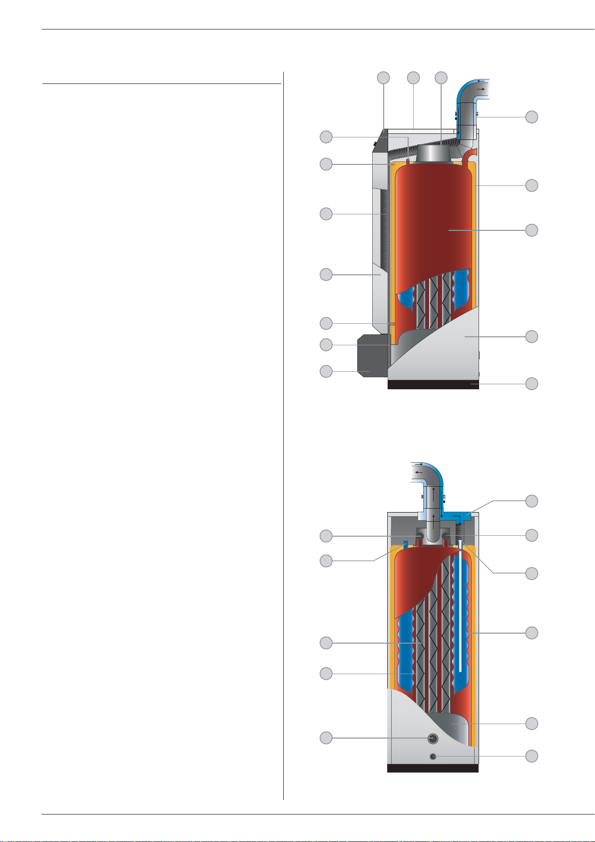
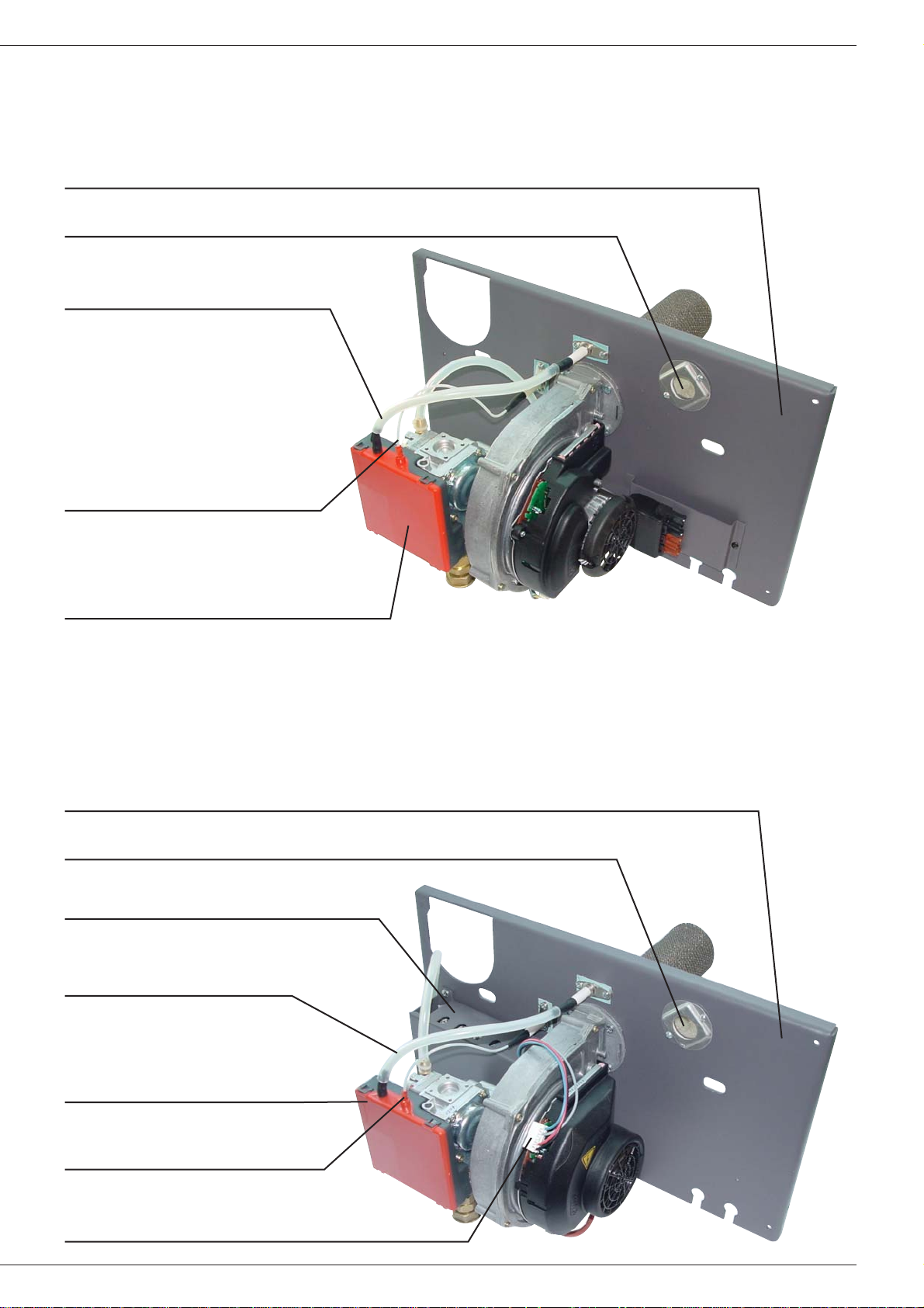
BOILER VIEWS AND KEY TO PARTS
1. Control panel
2. Detachable casing cover
(access to baffles)
3. Chimney reducing pipe
4. Measuring unit with condensate trap
(optional)
5. Polyurethane foam insulation
6. Outer body containing the primary water
7. Side casing
8. Base
9. Burner cover
10. Burner chamber plate
11. Control thermostat bulb
(model SV)
Potentiometer bulb (model MV)
12. Detachable front panel
13. Air supply pipe to venturi
14. Manual reset high limit thermostat (103°C)
15. Bulb of the thermal reset high limit thermostat (95°C)
16. Balanced flue adapter
17. Heating return
18. Cold water inlet
19. Inner annular tank containing hot water
20. Combustion chamber
21. Boiler drain cock
22. Heating return
23. Flue ways
24. Baffles
25. Hot water outlet
26. Heating out
DESCRIPTION
4
5
8
7
6
14
13
10
12
11
9
17
21
19
20
26
22
24
23
1 32
25
16
18
15
Fig. 1:Right-hand side view of boiler
Fig. 2:Rear view of boiler
Page 7
5
TECHNICAL CHARACTERISTICS
GENERAL
The appliances are supplied fully assembled, tested and packed
standing on a timber base with impact protection strips and wrapped
in heat-shrunk plastic film. When the appliance arrives, remove the
packaging and check that no parts have been damaged in transit.
Refer to the dimensions and weights listed below for handling
purposes:
OPERATING CONDITION LIMITS
Maximum service pressure (tank filled with water)
- Heating circuit: 3 bar
- Hot water circuit: 10 bar
Test pressure
(tank filled with water)
- Heating circuit: 4.5 bar
- Hot water circuit: 13 bar
Operating temperature
- Maximum temperature: 90 °C
Water quality
• Chlorides: < 150 mg/l (304 stainless steel)
< 2000 mg/l (Duplex)
• 6 ≤ ph ≤ 8
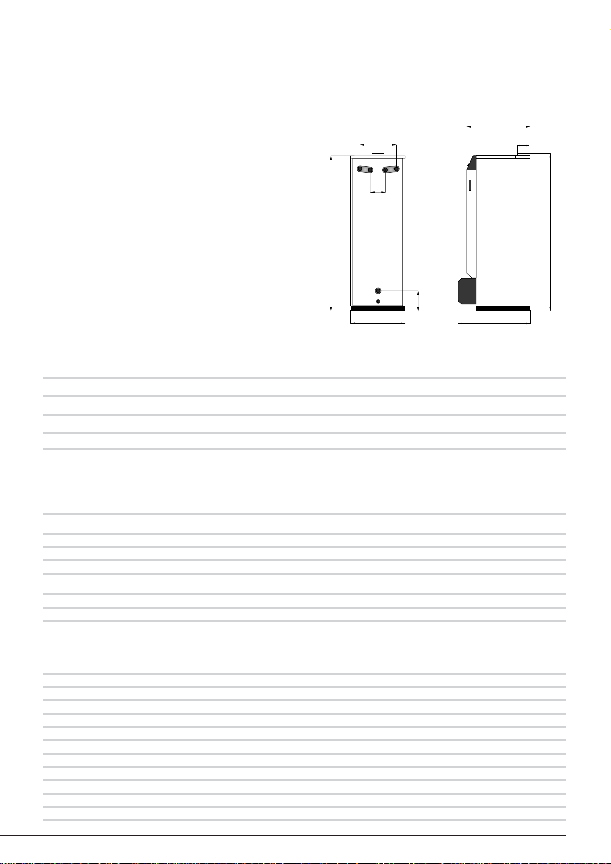
DIMENSIONS
F
G
I
H
B
C
D
A
E
HOT WATER OUTPUT DATA SV/35 SV/50 MV/35 MV/50
• Operating conditions at 80°C
Peak flow at 40°C (≤T = 30°C) l/10’ 291 328 291 328
Peak flow at 40°C (≤T = 30°C) l/60’ 1044 1393 1044 1393
Constant flow at 40°C (≤ T = 30°C) l/h 920 1352 920 1352
•Tank refill time at 60°C
Initial heating time minutes 20 13 20 13
After drawoff of 140 l at 45°C minutes 10 8 10 8
GENERAL CHARACTERISTICS SV/35 SV/50 MV/35 MV/50
Input kW 34.9 50 10 / 34.9 15 / 50
Output kW 32 46.7 9.5 / 32 14.5 / 46.7
Maintenance loss (60°C) % 0.5 0.5 0.5 0.5
Total capacity l 127 162 127 162
Heating circuit capacity l 62 82 62 82
Heating connection Ø 1” 1” 1” 1”
Hot water connection Ø 3/4” 3/4” 3/4” 3/4”
Water tank heat exchanger surface m
2
1.99 2.46 1.99 2.46
Combustion efficiency % 92.9 93.5 96.4 / 92.9 97 / 93.5
Average CO2 % 9999
Mass flow rate of combustion products g/sec. 16.1 23 4.6 / 16.1 23
A
mm
B
mm
C
mm
D
mm
E
mm
F
mm
G
mm
H
mm
I
mm
kg (*)
Delta Performance SV/35 1585 390 200 542 125 645 80/80/125 1610 800 182
Delta Performance SV/50 1830 390 200 542 125 645 100/100/150 1880 800 220
Delta Performance MV/35 1585 390 200 542 125 645 80/80/125 1610 800 182
Delta Performance MV/50 1830 390 200 542 125 645 100/100/150 1880 800 220
(*) The weights shown are drained weights.
Page 8
BOILER ROOM
Important
•Never obstruct the ventilation.
• Do not store inflammable products in the boiler room.
•Avoid storing corrosive products such as paint, solvents, chlorine,
salt, soap or other cleaning products near the boiler.
Accessibility
The boiler room should be big enough to allow easy access to the
boiler.Minimum clearances around the boiler (mm):
- to the front 500
- to the rear 150
- to the sides 100
- above 700
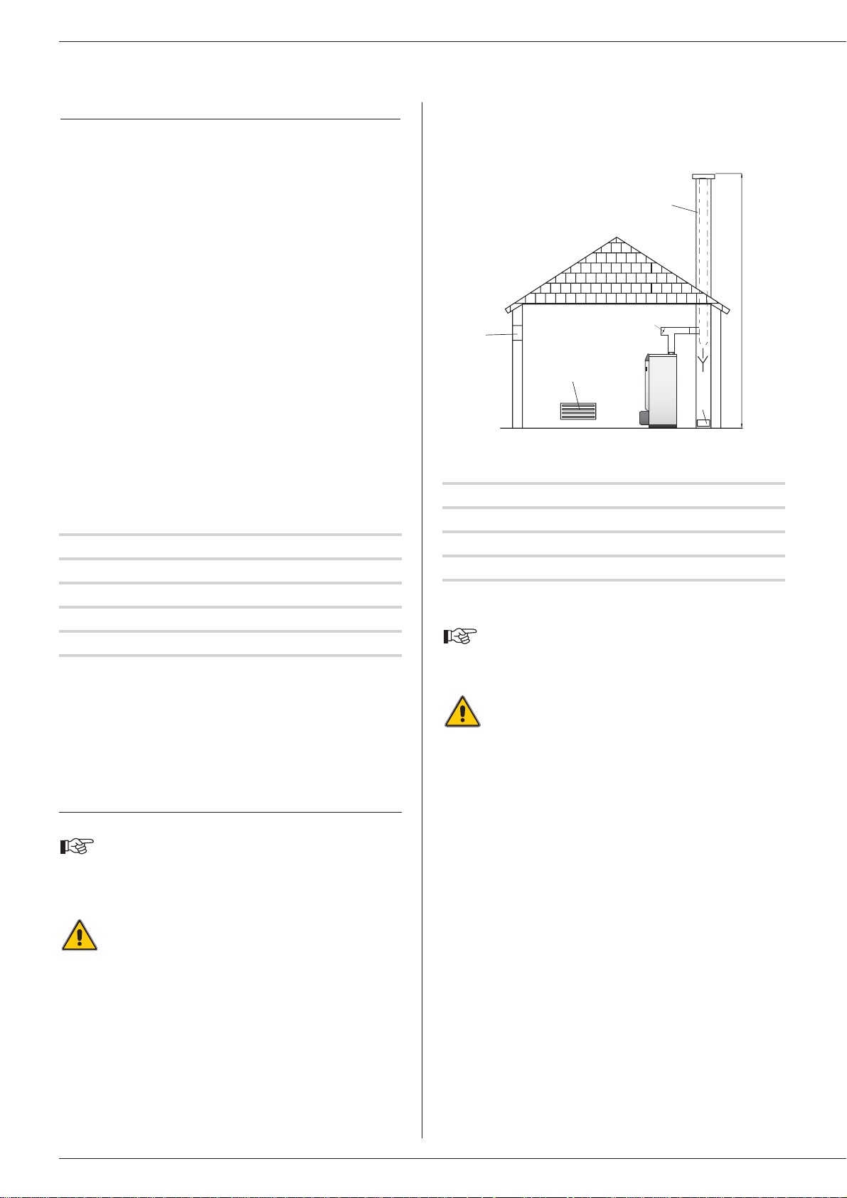
Ventilation
The boiler room must have both low and high level ventilation (see
Fig. 3)
.
By way of information, the table below gives the minimum
ventilation requirements according to Belgian regulations.
The user must ensure that his boiler room ventilation complies
with local regulations.
Chimney connector type: B23 (Fig.3)
The chimney must be connected to the boiler by means of a metal
pipe rising at an angle from the boiler to the chimney.
A chimney connection is required.
A. High level ventilation
B. Low leve l ventilation
C. Draught stabiliser
D. Flame inspection window
E. Height of lined chimney
F. Chimney diameter
SV - MV / 35 SV - MV / 50
Ventilation
Fresh air supply min. m3/h 63 90
High level ventilation (A) dm
2
1.5 1.5
Low level ventilation (B) dm
2
1.5 2
Draught stabiliser (C) Ø 80 100
N.B.:
The figures for (B) and (C) only apply to type B23 connectors.
Base
The base on which the boiler will be mounted must be made from
non-combustible materials.
CHIMNEY CONNECTIONS
IMPORTANT
The boiler must be installed by a qualified engineer in
accordance with the local standards and codes of
practice.
The diameter of the chimney must not be less than the
diameter of the boiler's chimney reducer.
Fig. 3:Boiler ventilation and chimney connection type B23
Important note:
The above table is shown by way of indication only as
regulations vary from country to country.
The high efficiency of our boilers means that the flue
gases exit at low temperature.The attendant risk of
condensation may cause damage to some chimneys.
To avoid this risk we strongly advise that you line the
chimney.
Please contact your installer for further information
about chimney lining.
SV - MV / 35 SV - MV / 50
Chimney
E = 5 m Ø min. F mm 213 236
E = 10 m Ø min. F mm 179 199
E = 15 m Ø min. F mm 162 179
6
INSTALLATION
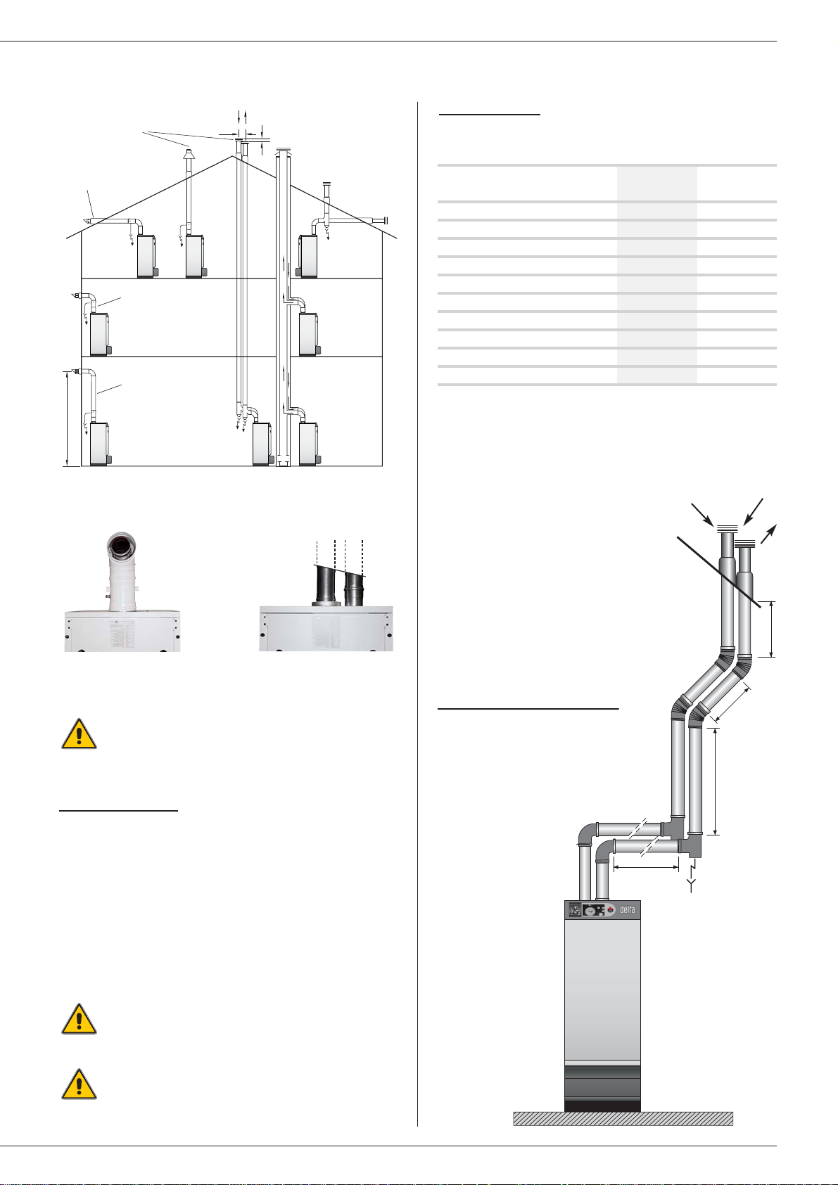
CHIMNEY CONNECTORS TYPE: C XX (Figs. 4, 5 and 6)
• C 13 (x): Concentric / parallel connector with horizontal terminal.
• C 33 (x): Concentric / parallel connector with vertical terminal.
• C 43 (x): Concentric / parallel connector for several boilers in a
common chimney.
• C 53 (x): Parallel chimney connector with air intake and flue gas
outlet in different pressure zones (different locations).
• C 63 (x): Connector for connection to an approved discharge system
(Netherlands, Germany and Luxembourg only).
A
B
F
E
C
D
Page 9
7
INSTALLATION
Fig. 5:
Concentric co
nnector
Fig. 6:
Parallel connector
Fig. 4:Chimney connectors type C xx
C33
Concentric connector
Maximum length concentric tubing:
6 metres due to the maximum air temperature at the venturi (70°C).
Note:
-A 90 degree bend = 1 metre equivalent length.
Example:
-6 metres concentric = one 90° bend + 4 metres horizontal +
outlet 1 metres.
“CE” approved according to EN 483
A drain outlet must be provided near the boiler to
prevent condensation from the chimney entering the
boiler.
All horizontal pipe runs must fall to the boiler to prevent
condensation water escaping from the terminal.
Parallel connector
Table of flue resistance in Pascal (max. 100 Pa)
(1 Pascal = 0,01 mbar)
SV - MV / 35 SV - MV 50
Ø 80 mm Ø 100 mm
Straight pipe L. 500 mm 1.18 1.82
Straight pipe L. 1000 mm 2.55 2.3
Straight pipe L. 2000 mm 5.1 4.6
90° pipe bend 4.32 6
45° pipe bend 2.75 3.1
30° pipe bend 1.67 1.7
5° pipe bend 0.69 0.76
Vertical terminal 5.4 3.53
Horizontal terminal 5.5 3.53
Condensation drain 2.06 1.53
This table is based on the equipment offered by ACV and connot be
applied generally.
Sample calculation
The diagram below consists of the
following parts (Ø 80 mm) :
•1 x Pipe bend 90°
•2 x Straight pipe L 2000 mm
•2 x Pipe bend 45°
•2 x Straight pipe L 1000 mm
•1 x Vertical terminal
•1 x Condensation drain vertical
Calculation:
•1 x 4,32 = 4,32
•2 x 5,1 = 10,2
•2 x 2,75 = 5,50
•2 x 2,55 = 5,10
•1 x 5,4 = 5,4
•1 x 2,06 = 2,06
Total: 32,58 x 2 = 65,16 Pa
This value is less
than the maximum
authorised resistance,
therefore the installation
is compliant.
A condensation drain outlet must be fitted close to the
boiler to prevent condensation products from the
chimney running into the boiler.
120
150 min.
C43
C13
2 m min.
C13
C13
C53
1000 mm
1000 mm
2000 mm
2000 mm
Page 10
Drain
The drain cock and safety v alve must be connected to the building dr ain.
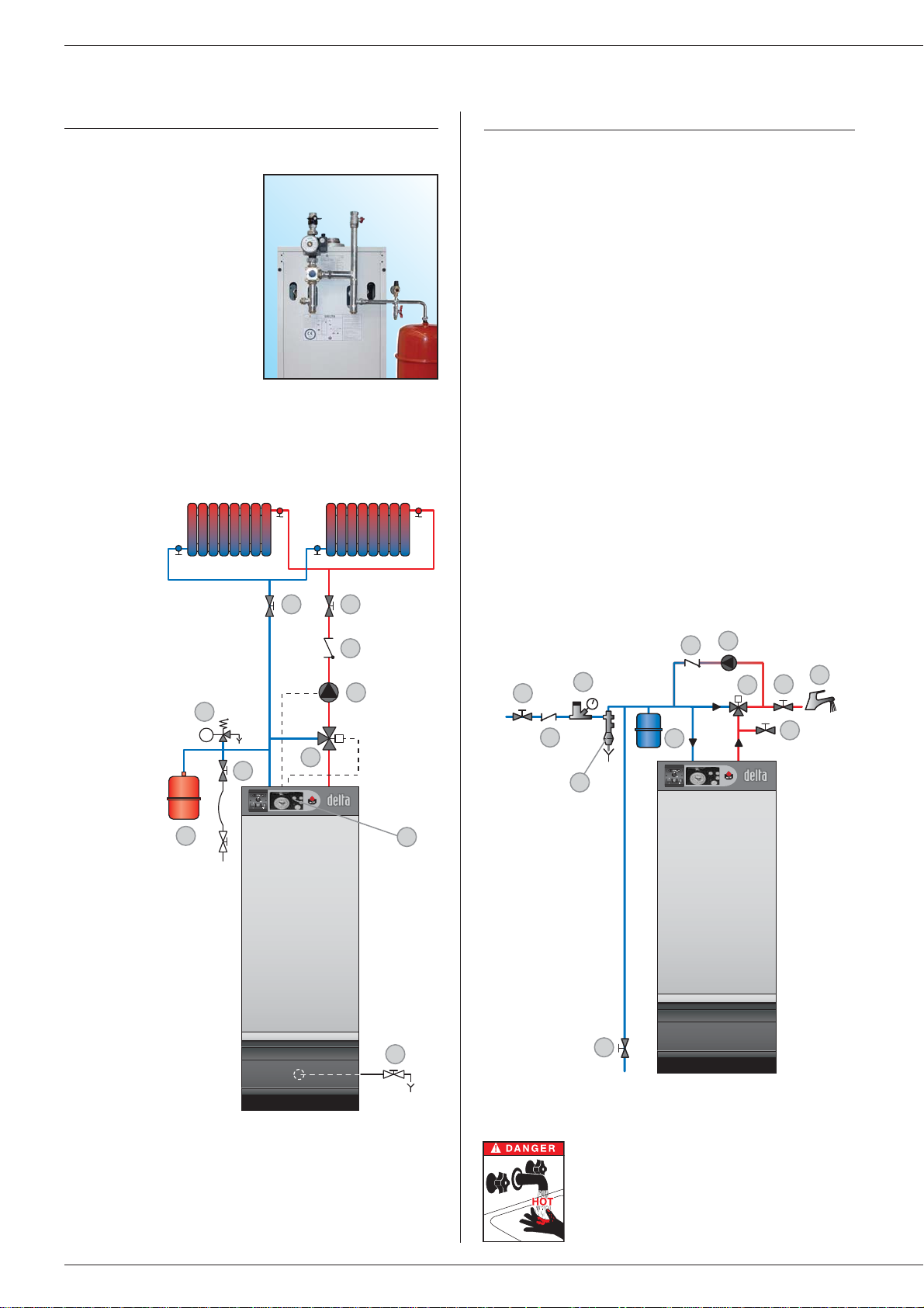
HOT WATER CONNECTION
Pressure reducing valve
If the mains water pressure exceeds 6 bar, a pressure reducing valve
calibrated to 4.5 bar must be installed.
Safety group
The safety group of the water tank must be approved by ACV and
calibrated to 7 bar; the group's valve discharge must be connected
to the drain.
Hot water expansion vessel
Installing a hot water expansion vessel will prevent any risk of excess
pressure due to water hammer or pressure fluctuations.
Hot water circulation
If the water tank is a long way from the point of use, installing a closed
recirculation circuit can ensure a faster hot water drawoff at any time.
Typical circuit with thermostat valve
1. Safety group
2. Pressure reducing valve
3. Thermostatic mixer
4. Hot water pump
5. Non-return valve
6. Hot water expansion vessel
7. Cold water supply tap
8. Drawoff tap
9. Drain cock
10. Air vent
11. Isolating valve
8
Fig. 8:Heating system layout
Fig. 9:Hot water system layout
INSTALLATION
9
5
6
2
1
3
8 8
4
7
7
3
10
11
8
4
5
6
9
5
2
1
IMPORTANT
As a safety measure, we strongly advise the
installation of a thermostatic mixer to prevent
any risk of burning to persons.
ACV kit water
ACV can supply an optional
pre-assembled water kit.This
kit comprises:
•A pump;
•A 3-way manual valve. This valve
can be motorised if required;
• Connection pipes that can be
used to connect a second
heating circuit;
•Two isolating valves;
• Connectors for the right or left
hand mounting of the expansion
vessel, the safety valve with
pressure gauge and the filling
valve.
(The expansion vessel is not
included)
.
Typical single circuit configuration
CONNECTING THE HEATING SYSTEM
1. 3-way motorised mixer valve.
2. Safety valve calibrated to
3 bar, with pressure gauge.
3. Pump.
4. Non-return valve.
5. System filling valve.
6. Expansion vessel.
7. Controller ACV 13.00
(see Controller Kit on page 9)
8. Isolating valve, heating system.
9. Drain cock.
fig. 7 :ACV water kit
Page 11
9
INSTALLATION
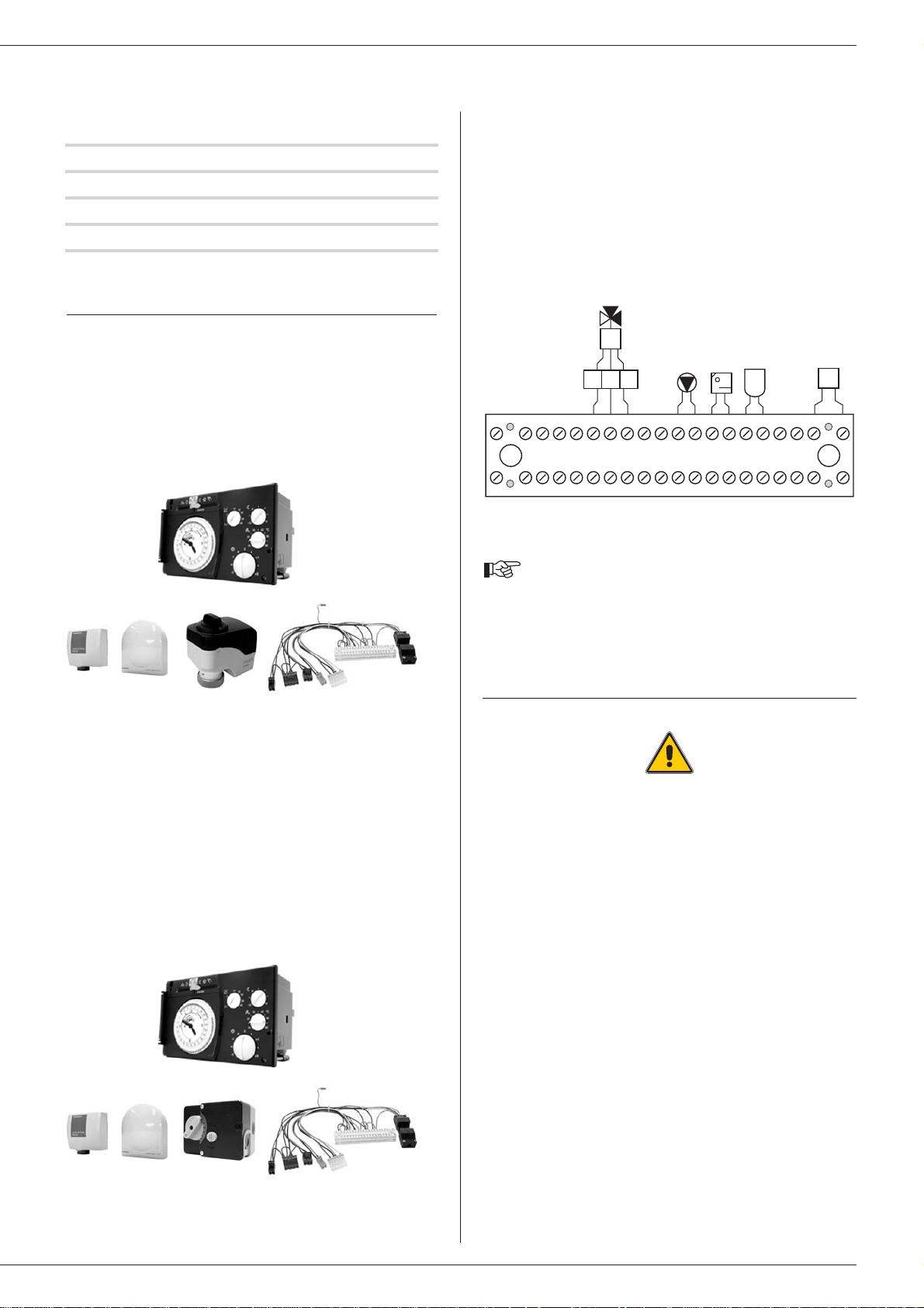
Optional accessories
CONTROLLER KITS
KIT 1: ACV 13.00 / Basic
This basic kit is used to control the hot water circuit outlet temperature
as a function of ambient conditions.
It comprises: a temperature controller with analog clock, a surfacemounted primary water temperature sensor (-30/130°C), an outdoor
sensor (-30/50°C), a servomotor SSY 319 230 V - 3-pin and an
intermediate socket.
Circuit diagram of ACV control kits
B2. Temperature sensor
B9. Outdoor sensor
B5. Analog/digital room sensor
P1. Pump
Y1/Y2/N. Servomotor (SSY 319 or SQK 349)
bl. Blue N
n/z. Black Y2
br. Brown Y1
Safety group Ø 3/4”
Pressure reducing valve Ø 3/4”
Thermostatic mixer Ø 3/4”
Expansion vessel 5 litres
KIT 2: ACV 13.00 / Standard
This basic kit is used to control the hot water circuit outlet temperature
as a function of ambient conditions.
It comprises: a temperature controller with analog clock, a surfacemounted primary water temperature sensor (-30/130°C), an outdoor
sensor (-30/50°C), a servomotor SQY 349 230 V - 3-pin and an
intermediate socket.
Please contact your installer for further details about
this.
CONNECTION TO THE GAS SUPPLY
- The boiler is fitted with a 3/4” M connector, to which you can
connect the gas tap.
-You must comply with the NBN D51-003 standard for connections
to the gas and, if applicable, with the other standards in force in
the location of the connection.
-Where there is a risk of dirt stemming from the network, place a
gas filter upstream from the connection.
-Drain the gas pipe and check in minute detail that all the boiler
pipes, both inside and outside, are sealed.
- Check the gas pressure in the system.
- Check the gas pressure and consumption when commissioning
the appliance.
SSY 319 / SQK 349
P1 B5 B9 B3 B2
QAAD50
(QAAD70)
QAC32 QAD22
bk br
bl
20 19 18 17 16 15 14 13 12 11 10 9 8 7 6 5 4 3 2 1
20 19 18 17 16 15 14 13 12 11 10 9 8 7 6 5 4 3 2
P1Y1Y2NB5B9B3B2
1
Page 12

10
INSTALLATION
z
Br
B
B
Br
Gr
G
Y
Bk
Br
BG 2000-SV
Delta Performance SV
Y/Gr
Br
Br
Or
BBB
B
Or
B
Y/Gr
Or
Gr
G
Bk
Y
B
Y/Gr
Y/Gr
12
1
3
4
711
10
9
8
2
6
5
7
ELECTRICAL CONNECTIONS
Principle of supply
The boiler operates on a single-phase supply of 230 V/50 Hz. You
should install a control box with main switch and 6 A fuses exter nally
to the boiler to allow the boiler to be isolated from the supply for
servicing and repairs.
Statutory compliance
The installation must comply with your local standards and codes of
practice.
Safety
The stainless steel water tank must be provided with a separate
earth.
The boiler must be isolated from the electrical supply
before any work is carried out on it.
Wiring for the SV boiler (Fig. 10)
1. Control thermostat (60/90°C)
2. Thermal reset high limit ther mostat (95°C)
3. Manual reset high limit thermostat (103°C max.)
4. Main switch
5. Reset
6. Burner shutdown indicator lamp
7. Summer/Winter switch
8. Power supply to boiler
9. Room thermostat
(optional)
10. Heating pump connection
11. Boiler electrical supply connection
(6-pin plug)
12. Burner connection
(7-pin plug)
Wiring for the MV boiler (Fig. 11)
1. Potentiometer (60/90°C)
2. Thermal reset high limit ther mostat (95°C)
3. Manual reset high limit thermostat (103°C max.)
4. Main switch
5. Reset
6. Burner shutdown indicator lamp
7. Summer/Winter switch
8. Power supply to boiler
9. Room thermostat (optional)
10. Heating pump connection
11. Boiler electrical supply connection
(6-pin plug)
12. Burner connection
(6-pin plug)
13. Fan connection (PWM and 230 V)
14. NTC sensor
15. Printed circuit board
16. Control/monitoring relay
Key to wiring
B. Blue
Bk. Black
Br. Brown
G. Grey
Gr. Green
Or. Orange
R. Red
W. White
Y. Yellow
Y/Gr. Yellow / Green
Delta performance SV (Fig. 10)
23456789101112
230V~50 H
Page 13

11
INSTALLATION
Bk
B
B
Y/Gr
Br
Gr
Y
G
G
Br
Y/Gr
B
Or Bk
Bk
B
B
Bk
Br
Y/Gr
B
R
G
GY
Y
Y
Or
Br
R
B
G
Y/Gr
R
B
Gr
Y/Gr
Br
B
Gr
G
B
R
Bk
Gr
B
Y/Gr
Br
Bk
Br
Gr
BWB
Bk
Br
Gr
W
B
Y
G
B
BG 2000-MV
Delta Performance MV
12 12
2
1 6 5
7 4
810 9
3
11
13
14
15
16
Start
Min.
Max.
Delta performance SV (Fig. 11)
1x5
1 2 3 4 5 6 7 8 9 10 11 12
21X4
+ -
P4
+ -
X7
1
2
3
4
5
6
P2
+ -
P3
1x4
GND
PWM
12 V
1234
HALL
X8
Pri 230V - 50/60 Hz
SEC 18V - 2,0 VA
Typ EI 30/15,5
BV 030-7308.OS
1x3
1x6
X3
7
RY2
6
4
3
X1
4
F1
3
2
1
2AT
NTC
S3T2T1NL1
S3T2T1NL1
12345
PWM
PhN
230 V-50Hz
1x7
1x3
S3S3T2T2T1T1NNL1
L1
S3S3T2T2T1T1NNL1
230V-50Hz
6A
L1
Page 14

12
BURNER CHARACTERISTICS
DESCRIPTION OF THE BURNER
Gas burner ACV BG 2000-SV
ACV BG 2000 air/gas premix burners are equipped with a gas valve ,
a venturi and a Honeywell electrical control relay.These items have
been specially developed for low NOx air/gas premix burners with
automatic ignition and flame detection.
Gas burner ACV BG 2000-MV
The ACV BG 2000-MV burner is based on the technology of the ACV
BG 2000-SV burner but offers the benefits of a modulating burner.
The burner's output is constantly adjusted to suit the fluctuating
demand for heat, thus optimising operating efficiency.
BG 2000-SV and MV burners are preset in our factory
for use with natural gas
(equivalent to G20).
CONVERSION TO PROPANE: (refer to the conversion instructions)
Prohibited in Belgium.
Conversion kit supplied with the boiler comprises:
- Orifice(s).
- Propane rating plate(s).
- Self-adhesive settings label.
- Conversion instructions.
BURNER BG 2000-SV AND MV
Venturi
Gas valve
Burner reset
(also on the control panel)
Control/monitoring relay
Venturi
Female gas connector 3/4”
NIT burner tube
Burner chamber plate sealing cord
Ionisation electrode
Ignition electrode
Burner chamber plate insulation
Page 15
13
BURNER CHARACTERISTICS
BURNER BG 2000-SV
BURNER BG 2000-MV
Burner chamber plate
Flame inspection window
Ignition cable
Ionisation cable
Control/monitoring relay
Burner chamber plate
Flame inspection window
Box containing the p.c.b.
Ignition cable
Ionisation cable
PWM connector
Control/monitoring relay
Page 16
14
BURNER CHARACTERISTICS
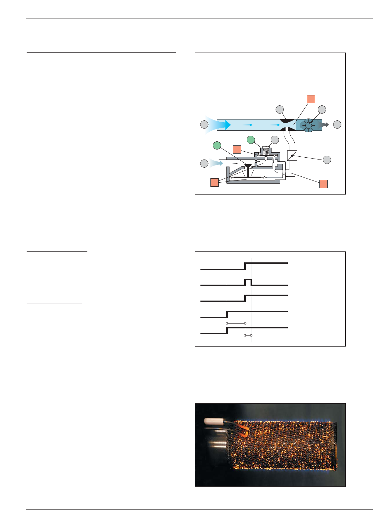
OPERATING PRINCIPLE OF THE BURNER
AIR/GAS mixture control (Fig. 12)
The fan draws air in across the v enturi.This creates a vacuum P1 at
the venturi neck. The gas valve regulator now reacts to maintain a
difference equal to the amount of the offset between the pressure at
the gas valve outlet P2 and atmospheric pressure P3:P2 – P3 = off-
set.
If the air flow decreases, P1 rises; the same applies to P2;now
P2>P3;the regulator R moves upwards and restores the equilibrium
P2 – offset = P3;pressure P4 falls and valve C moves down: the
gas flow decreases.
Whatever the speed of the fan therefore, the Air/Gas ratio is m ain-
tained equal to 1 to within the amount of the offset.
The difference in pressure between the neck of the venturi and the
outlet from the gas valve now draws gas through the venturi.
The gas flow adjuster screw is used to adjust the amount of gas that
is to be injected for a given air flow, and this will determine the %CO
2
in the flue gas. It is now a ver y simple matter to control the burner's
power by adjusting the fan speed and the %CO
2 to predefined
settings.
Ignition and flame monitoring
The control and monitoring relay has a dual function: it ignites the
burner by producing sparks at the ignition electrode, and it monitors
the actual presence of a flame when the gas valve is open (it measures
the ionisation current).
Starting sequence: (Fig. 13)
The fan starts up when the boiler thermostat/potentiometer detects
a demand for heat.After a 15 second pre-purge the gas valve opens
simultaneously with the ignition. Provided an ionisation current is
detected inside the first 5 seconds, combustion continues normally
until heat is no longer called for.Otherwise, the gas valve closes and
the fan stops; the burner is now shut down.
If the burner shuts down:
1. The burner indicator lamp lights up on the control panel and on
the burner.
2. Press the burner reset button on the control panel. Turn the
boiler off for sev eral seconds at the main switch, then restart the
the boiler.
Gas tube (Fig. 14)
The air/gas mixture leaving the gas valve/venturi assembly is
propelled into the burner tube.
This tube is covered with metal fibres (NIT). This enhances the
distribution of the flame, increasing its life and significantly reducing
pollutant emissions.
Combustion of the air/gas mixture is also spread uniformly around
the circumference of the tube. The tube is also designed to
withstand propane combustion.
1. Air
2. Gas
3. Venturi
4. Fan
5. Offset adjuster screw
6. Gas flow adjuster screw
(CO2)
7. Air/gas mixture
Fig. 12: Air/gas mixture control
Fig. 13: Starting sequence
Fig. 14:The NIT gas tube in operation
1 7
2
5
R
3 4
6
P1
P2
P3
P4
C
Ionisation
Thermostat
Fan
Gas valve opens
Ignition
15s
5s
Page 17
15
BURNER CHARACTERISTICS
SETTING PARAMETERS
GAS CATEGORIES
TYPE SV/35 SV/50 MV/35 MV/50
Input kW 34.9 50 10 / 34.9 15 / 50
Nominal output kW 32 46.7 9.5 / 32 14.5 / 46.7
Combustion efficiency - natural gas % 92.9 93.5 96.4 / 92.9 97 / 93.5
Offset mbar 00- 0.4 - 0.4
Starting speed r.p.m. --4000 4000
Min. speed r.p.m. --1370 1400
Max. speed r.p.m. 4600 4400 4600 4400
CO2 natural gas % 9999
CO2 propane % 11.0 / 11.2 11.0 / 11.2 11.0 / 11.2 11.0 / 11.2
Gas G20 - 20 mbar - I 2E(S)B - I 2 Er - I 2H - I 2ELL - I 2E
Flow m3/h 3.7 5.3 1.06 / 3.7 1.6 / 5.3
Gas G25 - 20 mbar - I 2ELL / 25 mbar - I 2L
Flow m3/h 4.31 6.15 1.24 / 4.31 1.85 / 6.15
Gas G31 - 30/37/50 mbar - I 3P
Flow m3/h 1.43 2.05 0.41 / 1.43 0.61 / 2.05
Burner chamber pressure mbar 0.2 0.2 0.2 0.2
Net T° of combusted gases °C 140 140 80 / 140 60 / 140
BE FR AT DK ES UK IT PT IE SE NL LU DE
I 2Er X
I 2E(S)B X
I 2H XXXXXXXX
I 3P X X XX XX
I 2L X
I 2ELL X
I 2E X
N.B.:
• The burners are preset in our factory for use with natural gas (equivalent to G20)
• An adjustement of the CO2 % is not allowed in Belgium. I 2E(S)B
Page 18
16
BURNER DISMANTLING PROCEDURE
For safety reasons it is essential that you isolate the
power supply and the gas supply valve before carrying
out any work on the burner.
Dismantling the burner
1. Remove the burner cover.
2. Disconnect the gas connector and the electrical plugs of the
burner.
3. Disconnect the air supply pipe from the venturi.
4. Take off the burner chamber plate by undoing the two retaining
nuts.
Burner re-assembly
The burner is re-assembled in the reverse order of dismantling
(Step 4 to Step 1).
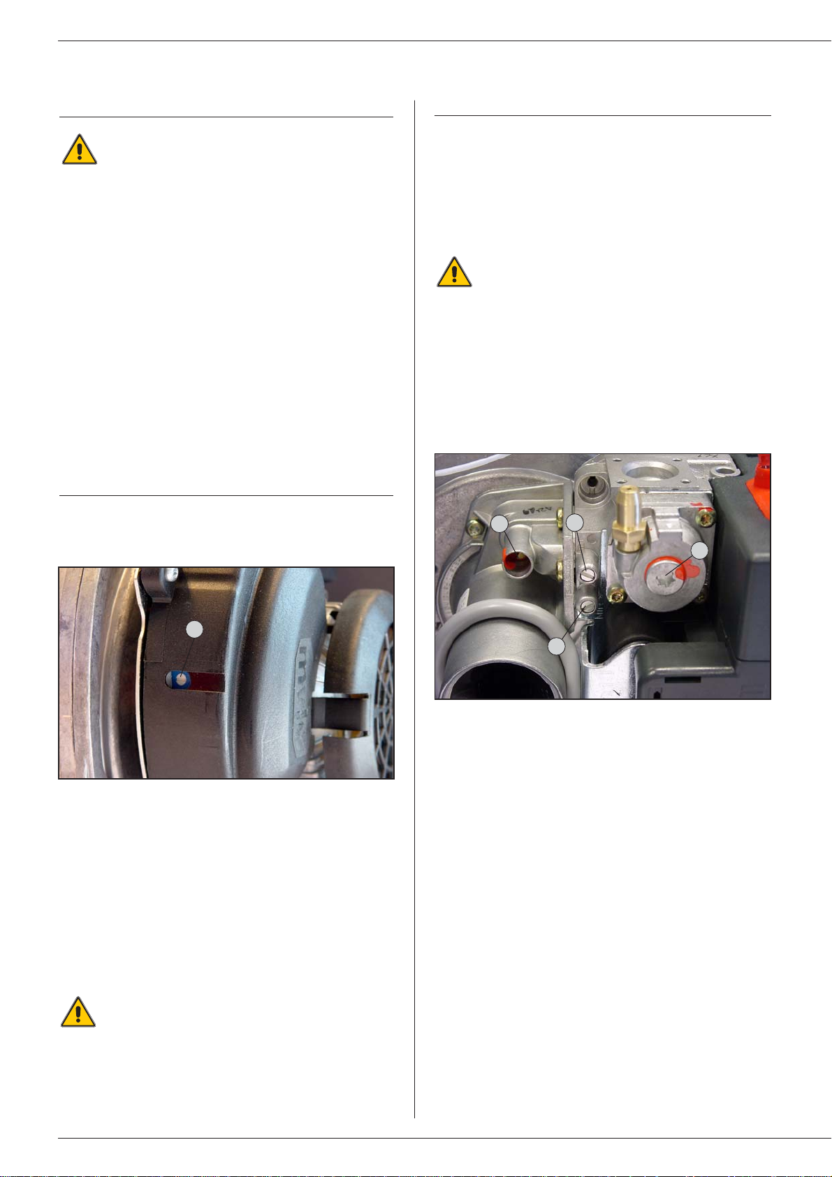
SETUP PROCEDURE IN THE EVENT OF FAN
REPLACEMENT
Fan speed for burner BG 2000-SV: (Fig. 15)
• Remov e the green plug on the front of the f an to gain access to the
adjuster screw on the potentiometer (A).
BURNER CHARACTERISTICS
1. Gas flow adjuster screw
2. Offset pressure measuring point
3. Upstream gas pressure measuring point
4. Offset adjuster screw cover
1
2
3
4
PROCEDURE FOR SETTING THE % OF CO2
•Measure the burner combustion with an electronic flue gas analyser.
• Adjust the % of CO
2 to the figure shown in the table of setting
parameters on Page 15 by turning the gas flow adjuster screw on
the gas valve.(Fig. 16)
Turn counter-clockwise (more gas) ➠ increases the % of CO
2.
Turn clockwise (less gas) ➠ reduces the % of CO2.
The offset (4) is set at the factory and requires no
adjustment.Nevertheless ACV recommends that you
check this setting. (Refer to the table of setting parameters).
You should contact your installer should you find any
significant deviation.
•Measure the speed of the impeller that is mounted on the motor
shaft. Adjust the speed of the fan according to the parameters
(Start, Min., Max.) listed in the table of setting parameters on Page
15 by turning the potentiometer screw (counter-clockwise to reduce
the fan speed and clockwise to increase it).
Fan speed for burner BG 2000-MV:
If the fan of a BG 2000-MV burner is replaced, the fan's speed is
controlled directly by the PWM connector which connects the fan to
the p.c.b.
The potentiometers on the p.c.b. (Start, Min. and Max.)
must be adjusted by an engineer approved by ACV.
A
Fig. 15
Fig. 16
Page 19

17
BURNER CHARACTERISTICS
ELECTRODE DISTANCE AND GAP
•Distance between ionisation electrode and tube:
X = 10 to 15 mm
(refer to Fig. 17)
•Distance between ignition electrode and tube:
Y = 4 to 7 mm (refer to Fig. 18)
•Ignition electrode gap:
Z = 2 to 5 mm
(refer to Fig. 19)
BURNER MAINTENANCE (refer to Fig. 20)
1. After dismantling the burner, check the condition of the ignition
electrode (1) and ionisation electrode (2), the insulation (3) and
the burner chamber plate seal (4). Replace these items if
necessary.
2. Check the condition of the tube (5).
3. Re-assemble the burner and check burner ignition.
4. Check the gas connection for leaks.
5. Check the combustion parameters.
Fig. 18
Fig. 17
Fig. 19
Fig. 20
X
Y
Z
2
3
5
1
4
Page 20

FAULT TABLE
18
BURNER CHARACTERISTICS
Corrective measures
Problems
Condensation in the chimney:
Smell of flue gas:
Insufficient heating:
The burner switches to safety mode after lighting:
Noisy pump:
Not enough hot water:
Pump not running:
Burner fails to light:
The manual reset high limit thermostat is tripped:
Reasons
Chimney is cold and/or not lined x1
Boiler T° is set too low xxx2
Chimney blocked x3
Combustion spillage in the chimney: x4
Insufficient or no ventilation in the boiler room x 5
Boiler clogged xxx6
Burner clogged xxxx 7
Room thermostat T° set too low x8
Pump jammed or faulty x x 9
Boiler switch is in the Summer position or is faulty x x x 10
Insufficient water in the system« x x x x x 11
Radiator valves closed x12
System not vented properly x x x 13
Low gas pressure xxx 14
Gas pipe too small xxx 15
Boiler thermostat/potentiometer faulty x x x 16
The electrical system is not earthed (properly) xx17
System fuses have blown x x x 18
System and/or boiler not vented properly x x x x 19
Not enough time allowed between large drawoffs x 20
Drawoff flow too fast x21
Room thermostat faulty or not turned on x x 22
Faulty Summer/Winter switch x x x x 23
Main switch is faulty or not turned on x x x x 24
Faulty NTC sensor x x x 25
Thermal reset high limit thermostat (95°C) activated x 26
Manual reset high limit thermostat (103°C) activated x 27
Faulty printed circuit board x 28
P.c.b.fuse blown x29
Faulty burner fan x30
No PWM signal x31
Ignition electrode faulty or incorrectly set x 32
Ionisation electrode faulty or incorrectly set x 33
Burner connectors not inserted properly x 34
Blocked gas valve x35
Faulty p.c.b. relay x 36
Boiler thermostat/potentiometer faulty x 37
Top of boiler not vented properly x 38
NTC sensor incorrectly inserted in its pocket x 39
Page 21

19
BURNER CHARACTERISTICS
Corrective measures
Fit lining in the chimney 1
Increase the boiler T° 2
Check and clean the chimney 3
Check and clean the chimney 4
Comply with local requirements governing boiler room ventilation 5
Clean the burner and the boiler 6
Clean the burner and the boiler 7
Set the room thermostat to the required temperature 8
Free the pump or replace it 9
Move the switch to the Winter position or replace it 10
Properly fill and vent the system and the boiler 11
Open the radiator taps or adjust the thermostat valves 12
Properly fill and vent the system and the boiler 13
Check that the pipes and the meter are suitable for the system 14
Check that the pipes and the meter are suitable for the system 15
Replace the boiler thermostat/potentiometer 16
Ensure that the electrical system complies with regulations 17
Replace the fuses and look for the cause of the problem 18
Properly fill and vent the system and the boiler 19
Adhere to the performance data as indicated by ACV 20
Adhere to the performance data as indicated by ACV 21
Set the thermostat to the required temperature or replace it 22
Replace the Summer/Winter switch 23
Replace the main switch 24
Replace the NTC sensor 25
Replace the boiler thermostat/potentiometer 26
Abnormal situation 27
Replace the p.c.b. 28
Replace the p.c.b.but look for the cause of the malfunction 29
Replace the fan 30
Replace the p.c.b.if the fan turns but does not send a PWM signal 31
Replace the electrode or set it correctly 32
Replace the electrode or set it correctly 33
Insert the connectors correctly 34
Replace the gas valve and set it up according to the setting parameters 35
Replace the p.c.b. 36
Replace the boiler thermostat/potentiometer 37
Fill and vent the system and the boiler 38
Insert the NTC sensor in the pocket correctly 39
ACV provides details of training courses on the maintenance of BG 2000 burners
TABLE OF CORRECTIVE MEASURES
Page 22

FILLING THE HOT WATER AND HEATING CIRCUITS
IMPORTANT
It is essential that the water tank is under pressure
before the heating circuit is filled.
1. Fill the hot water circuit and pressurise it.
2. Fill the heating circuit - do not exceed a pressure of 2 bar.
3. Vent the air in the top of the boiler.
4. Once you have vented the system, return the pressure to static
pressure plus 0.5 bar.
Height of the heating system:
• 10 m ➠ heating circuit pressure = 1.5 bar
• 15 m ➠ heating circuit pressure = 2 bar
USING THE BOILER FOR THE FIRST TIME
1. Check the gas supply connection and ensure that it is free from
leaks.
2. Check the electrical connection to the boiler and the boiler room
ventilation, and ensure that the flue gas discharge pipes and the
burner chamber plate are properly gas tight.
3. Set the boiler thermostat or potentiometer to between 60 and
90°C.
4. Move the Summer/Winter switch to the required position.
5. Move the main switch to “ON”.
6. Carry out the necessary venting operations, measurements and
settings.
RECOMMENDATION
ACV recommends that you have the boiler ser viced at least once a
year.Boiler servicing and checking must be carried out by a qualified
engineer.
BOILER MAINTENANCE (refer to Figs.1 and 2 on Page 4)
1. Isolate the boiler from the electrical supply at the
switch on the external control box, and close the gas supply valve.
2. Move the main switch on the control panel to “OFF”.
3. Remove the boiler cover (2) and dismantle the upper section of
the chimney reducer (3).
4. Remove the baffles (24) from the flue ways (23) and clean them.
Replace these items if worn.
5. Remove the burner cover and burner.
6. Brush the flue ways (23).
7. Clean the combustion chamber (20) and the burner.
8. Check the condition of the seal on the burner chamber plate.
MAINTENANCE OF SAFETY EQUIPMENT
- Check that all thermostats and safety devices operate correctly:
boiler thermostat/potentiometer, thermal reset high limit thermostat
and manual reset high limit thermostat.
- Check the safety valves in both the heating circuit and the
hot water circuit.
DRAINING THE BOILER
The water draining from the drain cock is very
hot and can cause serious burns. Keep all
persons away from running hot water.
Draining the heating circuit (refer to Fig. 8 on Page 8)
1. Move the main switch on the control panel to “OFF”, isolate the
boiler from the electrical supply at the switch on the external
control box and close the gas supply valve.
2. Close the isolating valves (8) in the heating circuit.
3. Connect a flexible tube to the drain cock (9).
4. Open the drain cock (9) to drain the heating circuit.
Draining the hot water circuit (refer to Fig. 9 on Page 8)
1. Move the main switch on the control panel to “OFF”, isolate the
boiler from the electrical supply at the switch on the external
control box and close the gas supply valve.
2. Release the pressure in the heating circuit until the pressure
gauge reads zero.
3. Close the tap (7) and the isolating valve (11).
4. Open the drain cock (9) and air vent (10) (first 9 then 10).
5. Allow the hot water circuit to discharge to the drain.
The drain cock (9) must be at ground level for the
circuit to drain fully.
MAINTENANCE
20
COMMISSIONING
Page 23

21
USE OF THE BOILER
We recommend that you have your system serviced
each year by a qualified engineer.
Starting the burner:
In normal operation the burner starts automatically if
the temperature of the boiler is below setpoint.
Before carrying out any work on the boiler, isolate it
from the electrical supply at the switch on the external
control box.
Also move the main switch on the control panel to
“OFF”.
You should familiarise yourself with the control panel
(Fig. 25)
The user must not attempt to gain access to the
components inside the control panel.
1. Control thermostat (SV) or potentiometer (MV)
If the boiler is being used to generate hot water only, the boiler
temperature can be set to between 60 and 90°C. If the boiler is
being used for hot water and heating, then the boiler's control
thermostat or its potentiometer should normally be set to 80°C to
guarantee optimum operating conditions.
2. Main switch
This switch is used to start and stop the boiler
3. Summer/Winter switch
This switch is used to start and stop the heating pump (if a pump is
fitted).
4. Thermometer
The thermometer shows the boiler temperature in the heating
circuit.This temperature should not exceed 90°C.If it does, stop the
boiler and check the settings on the thermostat (SV) or potentiometer
(MV). If the problem persists, contact your installer for advice.
5. Resetting the burner
This switch can be used to restart the burner if it has shut down.
6. Burner indicator lamp
This lamp tells the user whether the burner has shut down (lamp on)
or not (lamp off).
7. Controller
(optional)
Refer to the instructions supplied with the controller if you have this
option.
Gauge pressure in the heating system
Your system must be equipped with a heating safety valve calibrated
to 3 bar and fitted with a pressure gauge.
Ensure that the system is always under water pressure.When the
system is cold and the air inside it has been vented, the gauge must
indicate a pressure between 0.5 and 1.5 bar depending on the
height of the building.
To add water:
(refer to Fig. 8 on Page 8)
•Open the filling valve (5).
•
Close the valve properly after filling.
•Vent the system in order to obtain
an accurate reading of the
pressure inside the heating circuit.
Safety valves (heating circuit)
If water is found to be escaping from one of the safety valves, stop
the boiler and contact your installer for advice.
A monthly test is recommended: Lift the lever on the drain cock for
a few seconds to ensure that the safety valve is working correctly.
If there is a problem after this short test, please
contact your installer for advice.
Safety group (hot water circuit)
A monthly test is recommended:
Lift the lever on the drain cock for a few seconds to ensure that the
safety group is working correctly.
If there is a problem after this short test, please
contact your installer for advice.
Water escaping from the safety valve or safety
group can be extremely hot and cause very
serious burns.
USER GUIDE
1 4 7
2 3 5 6
Fig. 25: Control panel
Page 24

22
USER GUIDE
BURNER SHUTDOWN
If the burner is not working:
1. The burner indicator lamp lights up on the control panel.
2. Press the burner reset button on the control panel. Now switch
off the boiler for a few seconds at the main switch and then
restart it.
If the burner does not operate, isolate the boiler's
electrical supply at the switch on the external control
box before removing the front panel of the casing.
3. Reset the manual reset high limit thermostat on the top of the
boiler.
Wait until the boiler temperature has fallen to below
60°C, then refit the front panel of the casing.
5. If the problem persists, please contact your installer for advice.
Starting the burner.
In normal operation the burner starts automatically if the temperature
of the boiler is below setpoint.
To ensure that your system operates correctly, please
have it serviced annually by a qualified engineer;
servicing should be done before the start of the
heating season.
Page 25

23
SPARE PARTS
Codes
N° Casing Delta Delta
SV/MV - 35 SV/MV - 50
A01 Body shell 30537389 30537227
A02 Front panel 21473397 21473398
A03 Left-hand side panel 21472397 21472398
A04 Right-hand side panel 21471397 21471398
A05 Rear panel 21474397 21474398
A06 Large top cover 21475397 21475397
A07 Small top cover 21478397 21478398
A08 Bur ner cover 21476397 21476397
A09 Control panel 21477342 21477342
A02
A09
A03
A01
A08
A07
A04
A05
A06
Page 26

24
SPARE PARTS
Codes
N° Accessories SV 35 SV 50 MV 35 MV 50
B01 Complet control panel 24614063 24614063 24614065 24614065
B02 Test panel (SV) 54761004 54761004 - B03 Test panel (MV) - - 54761005 54761005
B04 Summer/Winter switch 54766007 54766007 54766007 54766007
B05 Ther mal reset high limit ther mostat (95°C) 54322000 54322000 54322000 54322000
B06 Manual reset high limit ther mostat (103°C) 54764010 54764010 54764010 54764010
B07 6-pin link (T1-T2) 257F1026 257F1026 257F1026 257F1026
B08 NTC sensor 12kOhm - - 547D3018 547D3018
PVCC Plunger Ø 19.5 mm / L. 800 mm 49410045 - 49410045 B09 PVCC Plunger Ø 19.5 mm / L. 1000 mm - 49410039 - 49410039
B10 Brass pocket Ø 1/2” / L. 100 mm 63438001 63438001 63438001 63438001
B11 Upper turbulator Type A 507F2009 507F2009 507F2009 507F2009
B12 Lower turbulator Type B 507F2010 507F2010 507F2010 507F2010
B13 Chimney reducer 507F3037 507F3042 507F3037 507F3042
Balanced flue adapter Ø 80/125 mm 507F3038 - 507F3038 B14 Balanced flue adapter Ø 100/150 mm - 507F3043 - 507F3043
B15 “Cérablanket” insulation 51305000 51305000 51305000 51305000
B16 Master-Neo tube Ø 80 / L. 2 m 537D6137 537D6137 537D6137 537D6137
B17 Drain cock Ø 1/2” 55426001 55426001 55426001 55426001
B18 Chimney reducer seal Ø 325 557A0016 557A0016 557A0016 557A0016
Rubber seal Ø 80 557D2003 - 557D2003 B19 Rubber seal Ø 100 - 557A0049 - 557A0049
B20 Bend 90° Ø 50 mm 537D6090 537D6090 537D6090 537D6090
B21 Plastic reducer Ø 80/50 mm 537D6092 537D6092 537D6092 537D6092
B22 Clip retainer 47405004 47405004 47405004 47405004
B23 Clip stud 47405005 47405005 47405005 47405005
B24 Plastic reducer Ø 100/80 mm - 537D6172 - 537D6172
Page 27

25
SPARE PARTS
Codes
N° Burner BG 2000 SV 35 SV 50 MV 35 MV 50
B25 NIT tube 537DZ017 537DZ017 537DZ017 537DZ017
B26 Ignition electrode (bent) 537DX016 537DX016 537DX016 537DX016
B27 Ionisation electrode (bent) 537DX010 537DX010 537DX010 537DX010
B28 Ignition cable 537D5000 537D5000 537D5000 537D5000
B29 Ionisation cable 537D5001 537D5001 537D5001 537D5001
Venturi VF002 537D4034 - 537D4034 -
B30 Venturi VF051 - 537D4028 - 537D4028
B31 Gas valve 537D4009 537D4009 537D4009 537D4009
B32 Control/monitor ing relay 54768005 54768005 54768005 54768005
B33 Ceramic fibre cord 51700025 51700025 51700025 51700025
B34 Bur ner chamber plate insulation 51401049 51401049 51401049 51401049
B35 Flame inspection window + glass 50423365 50423365 50423365 50423365
B36 Gas valve flange Ø 1/2” + accessories 53402088 53402088 53402088 53402088
Orifice 52 (propane) 537D4020 - 537D4020 -
B37 Or ifice 68 (propane) - 537D4037 - 537D4037
B38 Pressure tapping 53437039 53437039 53437039 53437039
B39 Circular seal (flame inspection window) 55412000 55412000 55412000 55412000
B40 Fan/door seal 55700026 55700026 55700026 55700026
B41 Tube seal Ø 107 x 1 mm 55700028 55700028 55700028 55700028
B42 Ignition electrode seal 557A0012 557A0012 557A0012 557A0012
B43 Ionisation electrode seal 55437034 55437034 55437034 55437034
B44 Venturi cork seal 557A0026 557A0026 557A0026 557A0026
B45 Venturi O-ring 557D6039 557D6039 557D6039 557D6039
B46 Fan + potentiometer 537D3008 537D3008 - B47 Fan - - 537D3027 537D3027
B48 P.c.b. box - - 2147B263 2147B263
B49 Box cover - - 2147C263 2147C263
B50 Box + p.c.b. + wiring - - 5476G012 5476G013
B51 Bur ner wir ing for BG 2000-SV 25760042 25760042 - B52 Bur ner BG 2000-SV 237D0096 237D0102 - B53 Bur ner BG 2000-MV - - 237D0098 237D0104
Page 28

26
SPARE PARTS
B01 B03 B04B02
B05 B07 B08B06
B09 B11 B12B10
B13 B15 B16B14
B17 B19 20B18
B21 B23 B24B22
Page 29
27
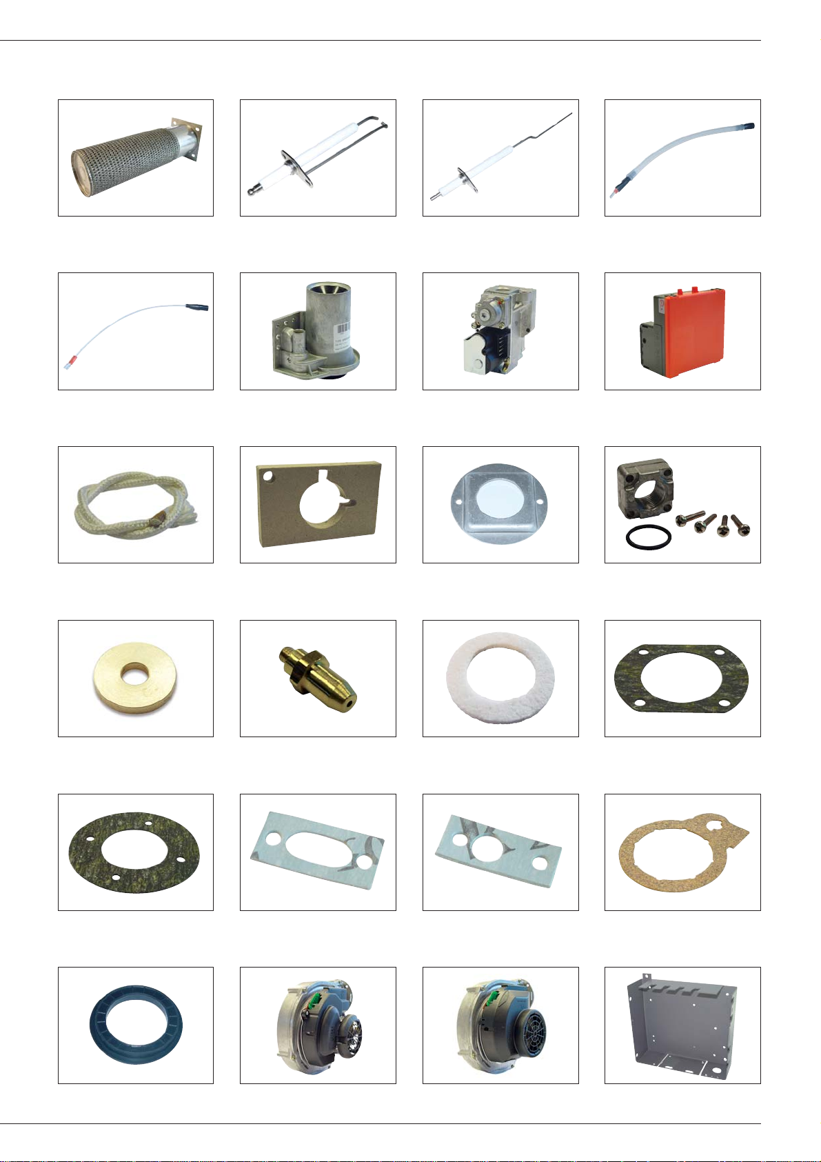
SPARE PARTS
B25 B27 B28B26
B29 B31 B32B30
B33 B35 B36B34
B37 B39 B40B38
B41 B43 B44B42
B45 B47 B48B46
Page 30

28
SPARE PARTS
B49 B51 B52B50
B53 - --
- - --
- - --
- - --
- - --
Page 31

29
SERVICE RECORD
Installation date:
% CO2 (min. load):
% CO2 (max. load):
Gas
Propane
Model:
Serial number:
Heating system pressure setting:
❏
❏
Name and signature:
Flue gas T°:
Efficiency:
Gas pressure:
DETAILS OF THE INSTALLATION
Service date:
% CO2 (min. load):
% CO2 (max. load):
Gas
Propane
Comments:
❏
❏
Name and signature:
Flue gas T°:
Efficiency:
Gas pressure:
SERVICE NOTES
Service date:
% CO2 (min. load):
% CO2 (max. load):
Gas
Propane
Comments:
❏
❏
Name and signature:
Flue gas T°:
Efficiency:
Gas pressure:
Service date:
% CO2 (min. load):
% CO2 (max. load):
Gas
Propane
Comments:
❏
❏
Name and signature:
Flue gas T°:
Efficiency:
Gas pressure:
Service date:
% CO2 (min. load):
% CO2 (max. load):
Gas
Propane
Comments:
❏
❏
Name and signature:
Flue gas T°:
Efficiency:
Gas pressure:
Service date:
% CO2 (min. load):
% CO2 (max. load):
Gas
Propane
Comments:
❏
❏
Name and signature:
Flue gas T°:
Efficiency:
Gas pressure:
Page 32

30
SERVICE RECORD
Service date:
% CO2 (min. load):
% CO2 (max. load):
Gas
Propane
Comments:
❏
❏
Name and signature:
Flue gas T°:
Efficiency:
Gas pressure:
Service date:
% CO2 (min. load):
% CO2 (max. load):
Gas
Propane
Comments:
❏
❏
Name and signature:
Flue gas T°:
Efficiency:
Gas pressure:
Service date:
% CO
2
(min. load)
:
% CO
2
(max. load)
:
Gas
Propane
Comments:
❏
❏
Name and signature:
Flue gas T°:
Efficiency:
Gas pressure:
Service date:
% CO2 (min. load):
% CO2 (max. load):
Gas
Propane
Comments:
❏
❏
Name and signature:
Flue gas T°:
Efficiency:
Gas pressure:
Service date:
% CO2 (min. load):
% CO2 (max. load):
Gas
Propane
Comments:
❏
❏
Name and signature:
Flue gas T°:
Efficiency:
Gas pressure:
Service date:
% CO2 (min. load):
% CO2 (max. load):
Gas
Propane
Comments:
❏
❏
Name and signature:
Flue gas T°:
Efficiency:
Gas pressure:
Page 33

31
SERVICE RECORD
Service date:
% CO2 (min. load):
% CO2 (max. load):
Gas
Propane
Comments:
❏
❏
Name and signature:
Flue gas T°:
Efficiency:
Gas pressure:
Service date:
% CO2 (min. load):
% CO2 (max. load):
Gas
Propane
Comments:
❏
❏
Name and signature:
Flue gas T°:
Efficiency:
Gas pressure:
Service date:
% CO
2
(min. load)
:
% CO
2
(max. load)
:
Gas
Propane
Comments:
❏
❏
Name and signature:
Flue gas T°:
Efficiency:
Gas pressure:
Service date:
% CO2 (min. load):
% CO2 (max. load):
Gas
Propane
Comments:
❏
❏
Name and signature:
Flue gas T°:
Efficiency:
Gas pressure:
Service date:
% CO2 (min. load):
% CO2 (max. load):
Gas
Propane
Comments:
❏
❏
Name and signature:
Flue gas T°:
Efficiency:
Gas pressure:
Service date:
% CO2 (min. load):
% CO2 (max. load):
Gas
Propane
Comments:
❏
❏
Name and signature:
Flue gas T°:
Efficiency:
Gas pressure:
Page 34

32
SERVICE RECORD
Service date:
% CO2 (min. load):
% CO2 (max. load):
Gas
Propane
Comments:
❏
❏
Name and signature:
Flue gas T°:
Efficiency:
Gas pressure:
Service date:
% CO2 (min. load):
% CO2 (max. load):
Gas
Propane
Comments:
❏
❏
Name and signature:
Flue gas T°:
Efficiency:
Gas pressure:
Service date:
% CO
2
(min. load)
:
% CO
2
(max. load)
:
Gas
Propane
Comments:
❏
❏
Name and signature:
Flue gas T°:
Efficiency:
Gas pressure:
Service date:
% CO2 (min. load):
% CO2 (max. load):
Gas
Propane
Comments:
❏
❏
Name and signature:
Flue gas T°:
Efficiency:
Gas pressure:
Service date:
% CO2 (min. load):
% CO2 (max. load):
Gas
Propane
Comments:
❏
❏
Name and signature:
Flue gas T°:
Efficiency:
Gas pressure:
Service date:
% CO2 (min. load):
% CO2 (max. load):
Gas
Propane
Comments:
❏
❏
Name and signature:
Flue gas T°:
Efficiency:
Gas pressure:
Page 35

Page 36

INTERNATIONAL
ACV international n.v
KERKPLEIN, 39
B-1601 RUISBROEK - BELGIUM
TEL.: +32 2 334 82 20
FAX:+32 2 378 16 49
E-MAIL: international.info@acv-world.com
BELGIUM
ACV BELGIUM nv/sa
KERKPLEIN, 39
B-1601 RUISBROEK-BELGIUM
TEL.: +32 2 334 82 40
FAX:+32 2 334 82 59
E-MAIL: belgium.info@acv-world.com
CHILE
ALBIN TROTTER Y ACV LTDA
SAN PABLO 3800
QUINTA NORMAL - SANTIAGO - CHILE
TEL.:+56 2 772 01 69
FAX:+56 2 772 92 62/63
E-MAIL: chile.info@acv-world.com
CZECH REPUBLIC
ACV CR SPOL. s.r.o
NA KRECKU 365
CR-109 04 PRAHA 10 - CZECH REPUBLIC
TEL.:+420 2 720 83 341
FAX:+420 2 720 83 343
E-MAIL: ceskarepublika.info@acv-world.com
DEUTSCHLAND
ACV WÄRMETECHNIK GMBH & CO KG
GEWERBEGEBIET GARTENSTRASSE
D-08132 MÜLSEN OT ST. JACOB - DEUTSCHLAND
TEL.:+49 37601 311 30
FAX:+49 37601 311 31
E-MAIL: deutschland.info@acv-world.com
ESPAÑA
ACV ESPAÑA
C/DE LA TEIXIDORA, 76
POL. IND. LES HORTES
E-08302 MATARÓ - ESPANA
TEL.:+34 93 759 54 51
FAX:+34 93 759 34 98
E-MAIL: spain.info@acv-world.com
FRANCE
ACV FRANCE sa
31, RUE AMPERE - Z.I MI - PLAINE
F-69680 CHASSIEU - FRANCE
TEL.:+33 4 72 47 07 76
FAX:+33 4 72 47 08 72
E-MAIL: france.info@acv-world.com
ITALIA
ACV ITALIA
VIA PANA 92
I-48018 FAENZA (RA) - ITALIA
TEL.:+39 0546 64 61 44
FAX:+39 0546 64 61 50
E-MAIL: italia.info@acv-world.com
NEDERLAND
ACV NEDERLAND bv
POSTBUS 350
NL-2980 AJ RIDDERKERK - NEDERLAND
TEL.:+31 180 42 10 55
FAX:+31 180 41 58 02
E-MAIL: nederland.info@acv-world.com
POLAND
ACV POLSKA sp. z.o.o.
UL.WITOSA 3
87 - 800 WLOCLAWEK - POLAND
TEL.:+48 54 412 56 00
FAX:+48 54 412 56 01
E-MAIL: polska.info@acv-world.com
PORTUGAL
BOILERNOX LDA
RUA OUTEIRO DO POMAR
CASAL DO CEGO, FRACÇÃO C,
PAVILHÃO 3 - MARRAZES
2400-402 LEIRIA - PORTUGAL
TEL.:+351 244 837 239/40
FAX:+351 244 823 758
E-MAIL: boilernox@mail.telepac.pt
RUSSIA
ACV RUSSIA
1/9, MALYI KISELNYI
103031 MOSCOW - RUSSIA
TEL.:+7 095 928 48 02 / +7 095 921 89 79
FAX:+7 095 928 08 77
E-MAIL: russia.info@acv-world.com
SLOVAK REPUBLIC
ACV SLOVAKIA s.r.o.
PLUHOVÁ 49
831 04 BRATISLAVA - SLOVAK REPUBLIC
TEL.:+421 2 444 62 276
FAX:+421 2 444 62 275
E-MAIL: slovakia.info@acv-world.com
SLOVENIA
ACV D.O.O. SLOVENIA
OPEKARNA 22b
1420 TRBOVLJE - SLOVENIA
TEL.:+386 356 32 830
FAX:+ 386 356 32 831
E-MAIL: slovenia.info@acv-world.com
UK
ACV UK Ltd
ST. DAVID’S BUSINESS PARK
DALGETY BAY - FIFE - KY11 9PF
TEL.:+44 1383 82 01 00
FAX:+44 1383 82 01 80
E-MAIL: uk.info@acv-world.com
USA
TRIANGLE TUBE PHASE III
FREEWAY CENTER - 1 TRIANGLE LANE
BLACKWOOD NJ 08012 - USA
TEL.:+1 856 228 8881
FAX:+1 856 228 3584
E-MAIL: sales@triangletube.com
excellence in hot water
www.acv-world.com
ARGENTINA
TECNOPRACTICA
ALFEREZ BOUCHARD 4857
1605 CARAPACHAY - BUENOS AIRES
TEL.: +54 11 47 65 33 35
FAX:+54 11 47 65 43 07
E-MAIL: jchas@tecnopractica.com
AUSTRALIA
HUNT HEATING PTY LTD
10 GARDEN BOULEVARD
3172 VICTORIA - AUSTRALIA
TEL.: +61 3 9558 7077
FAX:+61 3 9558 7027
E-MAIL: enquiries@huntheat.com.au
BRAZIL
SIMETAL INDUSTRIA E COMERCIO
DE FERRAMENTAS LTDA
RUA GERSON ANDREIS 535
95112 - 130 CAXIAS DO SUL - BRAZIL
TEL.: +55 54 227 12 44
FAX:+55 54 227 12 26
E-MAIL: export@simetall.com.br
BULGARIA
PROXIMUS ENGINEERING LTD
7 BIAL KREM STR.
9010 VARNA - BULGARIA
TEL.:+359 52 500 070
FAX:+359 52 301 131
E-MAIL: info@proximus-bg.com
CHINA
BEIJING HUADIAN HT POWER TECHNOLOGY
DEVELOPMENT CO. LTD
ROOM B-912, TOWER B, COFCO PLAZA
N°. 8, JIANGUOMENNEI AVENUE
BEIJING 100005 - PEOPLE’S REPUBLIC OF CHINA
TEL.:+86 10 652 30 363/393 EXT 101
FAX:+86 10 652 27 071
E-MAIL: li.zheng@acv-world.com
SHANGHAI COOLTECH LTD
14/F E. CHINA MERCHANTS PLAZA
N°. 333 CHENGDU ROAD (N)
200041 SHANGHAI - CHINA
TEL.:+86 21 52 98 11 22 - 820
FAX:+86 21 52 98 13 58
E-MAIL: cooltech@cooltech.sh.cn
DENMARK
VARMEHUSET
FRICHSVEJ 40 A
8600 SILKEBORG - DENMARK
TEL.:+45 86 82 63 55
FAX:+45 86 82 65 03
E-MAIL: vh@varmehuset.dk
ESTONIA
TERMOX AS
TAHE 112A
51013 TARTU - ESTONIA
TEL.:+372 736 73 39
FAX:+372 736 73 44
E-MAIL: termox@termox.ee
GREECE
ESTIAS
MARASLI STREET 7
54248 THESSALONIKI - GREECE
TEL.:+30 23 10 31 98 77 / +30 23 10 32 03 58
FAX:+30 23 10 31 97 22
E-MAIL: info@genikithermanseon.gr
ÎLE MAURICE
SOTRATECH
29, RUE MELDRUM
BEAU BASSIN - ÎLE MAURICE
TEL.:+230 46 76 970
FAX:+230 46 76 971
E-MAIL: stech@intnet.mu
LITHUANIA
UAB “GILIUS IR KO”
SAVARNORIU PR. 192
3000 KAUNAS - LITHUANIA
TEL.:+370 37 308 930
FAX:+370 37 308 932
MAROC
CASATHERM
PLACE EL YASSIR
20300 CASABLANCA - MAROC
TEL.:+212 22 40 15 23
FAX:+212 22 24 04 86
NEW ZEALAND
ENERGY PRODUCTS INTERNATIONAL
8/10 BELFAST PLACE
PO BOX 15058 HAMILTON - NEW ZEALAND
TEL.:+64 7 847 27 05
FAX:+64 7 847 42 22
E-MAIL: pmckenzie@tycoint.com
ÖSTERREICH
PROTHERM HEIZUNGSTECHNIK Gmbh
TRAUNUFERSTRASSE 113
4052 ANSFELDEN - ÖSTERREICH
TEL.:+43 7229 804 82
FAX:+43 7229 804 92
E-MAIL: protherm@nextra.at
ROMANIA
SC TRUST EURO THERM SA
D.N PIATRA NEAMT - ROMAN
km 2 C.P 5 O.P 3 jud. Neamt
5600 PIATRA NEAMT - ROMANIA
TEL.:+40 233 20 62 06
FAX:+40 233 20 62 00
E-MAIL: office@eurotherm.ro
TUNISIE
SO.CO.ME CHAUMAX
BOÎTE POSTALE N°44
1002 TUNIS - TUNISIE
TEL.:+216 71 78 15 91
FAX:+216 71 78 87 31
UKRAINE
UKRTEPLOSERVICE LTD
PR. LAGUTENKO 14
83086 DONETSK - UKRAINE
TEL.:+38 062 382 60 47/48
FAX:+38 062 335 16 89
 Loading...