

ACV deltaperformance 25, deltaperformance35, deltaperformance45, deltaperformance55, deltaperformanceF25 INSTALLATION OPERATING AND SERVICING INSTRUCTIONS
...Page 1
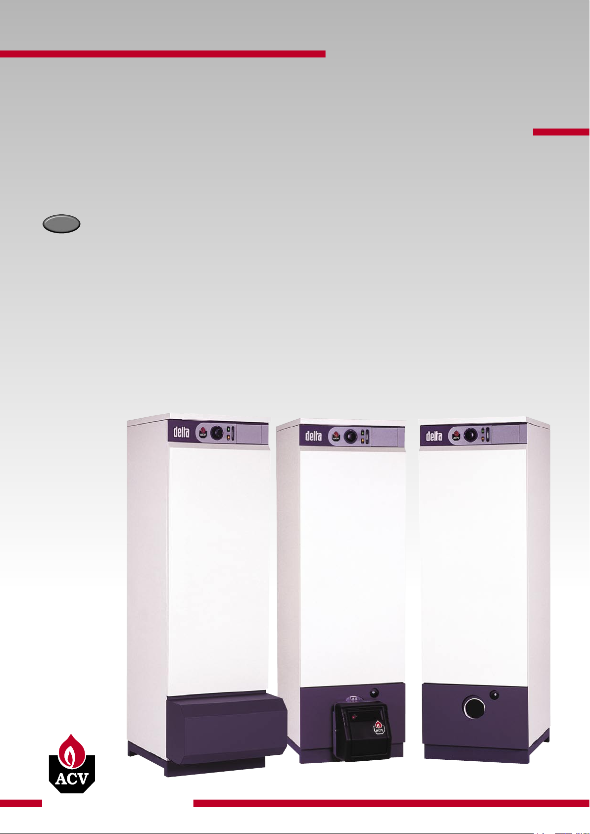
excellence in hot water
delta
performance
performance
25 / 35 / 45 / 55
F25 / F35 / F45 / F55
G25 / G35 / G45 / G55
16/12/2004 - 664Y0001
EN
INSTALLATION, OPERATING AND
SERVICING INSTRUCTIONS
Page 2

EN • 2
WARNINGS 3
Who should read this instructions 3
Symbols 3
Recommendations 3
Applicable standards 3
Important notes 3
INTRODUCTION 4
General description 4
Operating principle 4
Design characteristics 4
INSTRUCTIONS 6
You should familiarise yourself with the control panel 6
Pressure in the heating system 6
Burner shutdown 7
TECHNICAL CHARACTERISTICS 8
General 8
Operating condition limits 8
Dimensions 8
Domestic hot water output data 8
General characteristics 8
Boilers without burner 8
INSTALLATION 9
Boiler room 9
Chimney connection 9
Heating system connection 10
Domestic hot water connection 10
Controller kits 11
Oil supply 11
ELECTRICAL CONNECTIONS 12
Electrical boiler connection 12
Electrical burners connection 12
OIL BURNER CHARACTERISTICS 13
Description 13
Setting oil burner parametres 13
GAS BURNER CHARACTERISTICS 14
ACV BG 2000-S Air/Gas premix gas burner 14
Setting gas burner parametres 14
Gas categories 14
COMMISSIONING AND MAINTENANCE 16
Filling the hot water and heating circuits 16
Using the boiler for the first time 16
Recommendation 16
Maintenance of the boiler 16
Maintenance of the burner 16
Maintenance of safety devices 16
Draining the boiler 16
NOTES 18
SPARE PARTS See at the end of this manual
INDEX
Page 3
EN • 3
WHO SHOULD READ THESE INSTRUCTIONS
These instructions should be read by:
- the specifying engineer
- the installer
- the user
- the service engineer
SYMBOLS
RECOMMENDATIONS
• These instructions are an integral part of the equipment to
which they refer and the user must be provided with a copy.
• The product must be installed and serviced by qualified
engineers, in compliance with current standards.
• The manufacturer cannot accept liability for any damage
resulting from incorrect installation or from the use of
components or fittings not specified by the manufacturer.
• Any failure to follow instructions relating to tests and test
procedures may result in personal injury or risks of pollution.
• It is important to switch the boiler off before carrying out any
work.
• There are no user parts inside the control panel.
APPLICABLE STANDARDS
The products described in this document have been certified at
European level “CE” (European Directives 92/42/EEC “Efficiency”,
90/396/EEC “Gas devices”). They have be awarded the Belgian
label “HR+” (gas boilers) and “OPTIMAZ” (oil boilers).
IMPORTANTS NOTES
These instructions are an integral part of the equipment to which
they relate and must be handed to the user.
The product must be installed and serviced by qualified engineers
in accordance with the regulations in force.
The manufacturer declines all liability for any damage caused as a
result of incorrect installation or in the event of the use of appliances
or accessories that are not specified by the manufacturer.
The manufacturer reserves the right to change the
technical characteristics and specification of its products
without notice.
WARNINGS
Danger of burns
Essential instruction for
the safety of persons
and the environment.
Danger of electrocution.
Essential instruction for
the correct operation
of the installation.
Page 4

EN • 4
GENERAL DESCRIPTION
This boiler is available in 5 models.
• Combination boiler (central heating and domestic hot water).
• Designed for connection to a chimney.
• TANK-IN-TANK indirect storage type domestic hot water production.
• Equipment required: a water connection kit for heating circuit
supply (optional).
• The control panel contains a main switch, a control thermostat,
a thermometer, a Summer/Winter switch and knockout for the
built-in ACV control system (to be ordered separately).
• DELTA Performance 25, 35, 45 and 55 models - with effective
outputs adjustable between 22 and 62 kW - are shipped without
burners. They can be fitted with most gas or oil burners available
on the market.
• DELTA Performance F25, F35 and F45 models - with effective
outputs adjustable between 22 and 54 kW - are shipped with an
ACV BM R oil burner.
• DELTA Performance F55 models - with effective outputs
adjustable between 45 and 62 kW - are shipped with an ACV BM
oil burner.
• DELTA Performance G25, G35, G45 and G55 models - with
effective outputs adjustable between 22.5 and 49 kW - are
shipped with a BG 2000-S gas burner.
OPERATING PRINCIPLE
The “Tank-in-Tank” concept
The DELTA Performance series differs from traditional hot water
producers in that it has a ring-shaped tank immersed in the primary
fluid contained in the outer body. When hot water from the central
heating system or the domestic hot water system is needed, the
thermostat starts up the burner. The combustion gases quickly
heat up the primary fluid, thus creating a natural circulation around
the tank.
Indirect hot water heating
This circulation allows easier heat exchange between the primary
fluid and the domestic water, all over the tank surface. The
corrugations on the inner and outer shells of the ring-shaped tank
increase the area of heat exchange still further and thus speed up
the process of heating the domestic water.
Easy to control and safe
With a single command, the water temperature of both the
primary circuit and the domestic hot water circuit can be set by the
adjustable thermostat situated underneath the tank in the primary
circuit.
A cut-off thermostat, placed on the top of the boiler automatically
switches off the burner when the temperature of the water in
the primary circuit reaches 95°C. A manually resetable safety
thermostat switches off the burner if the temperature reaches
103°C.
DESIGN CHARACTERISTICS
Lining
The boiler is protected by a steel lining that first of all undergoes
a degreasing and phosphation process before being lacquered and
cured at 220°C.
Heating body
The boiler heat exchanger is constructed from carbon steel STW
22 with welded joints. It is hydraulically tested under a pressure of
4.5 bar (maximum working pressure = 3 bar).
“Tank-in-Tank” type storage exchanger
The ring-shaped inner tank is made from 18/10 austenitic
stainless steel and features a large heat exchanger surface for
rapid hot water heating. It is corrugated over its full height by
means of an exclusive production process, and is fully argon welded
using the TIG (Tungsten Inert Gas) method.
Combustion gas circuit
The combustion gas circuit is protected by high temperature paint.
The circuit comprises:
• Flue pipes
Depending on output, the various DELTA Performance models
contain either 4 or 8 steel flue pipes with an inner diameter of
64 mm. Each pipe is fitted with a special steel baffle designed to
improve heat exchange and reduce the flue gas temperature.
• Combustion camber
Sealed combustion chamber. The combustion chamber is water-
cooled.
Insulation
The boiler body has a full sprayed-on rigid polyurethane foam insulation
with a high insulation coefficient. No CFC emissions are created by
the spraying process.
Oil Burner BM R 31 BM R 51 BM 101
F25 / F35 - -
F45 - -
F55 - -
Gas Burner BG 2000-S
G25 / G35 / G45 / G55
Climatic controller
It is possible integrated a climatic controller in the control panel.
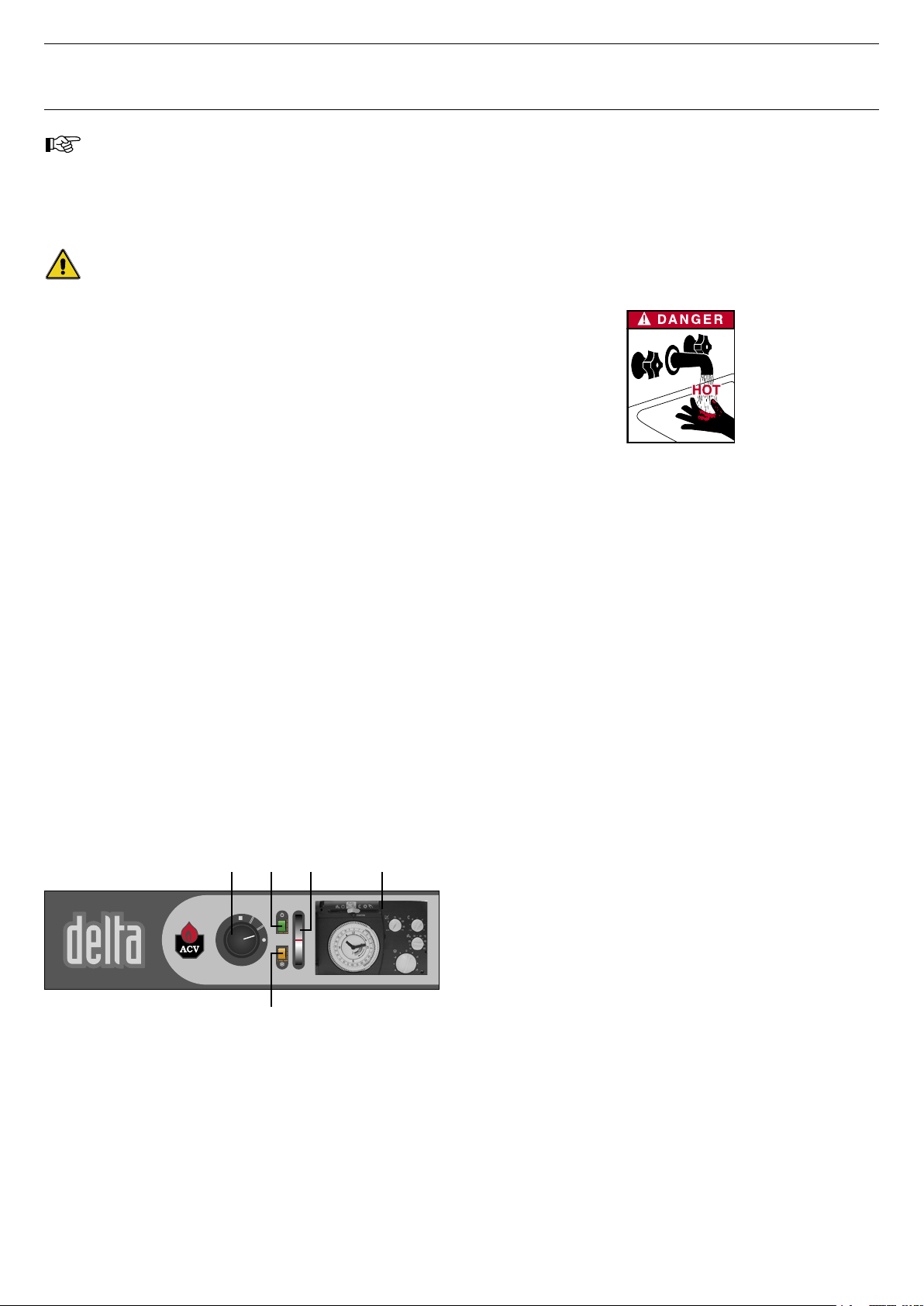
Control panel
1. Control thermostat (60/90°C)
2. Main switch
3. Summer/Winter switch
4. Thermometer
5. ACV Controller (opcional)
INTRODUCTION
4
3
51 2
Page 5
EN • 5
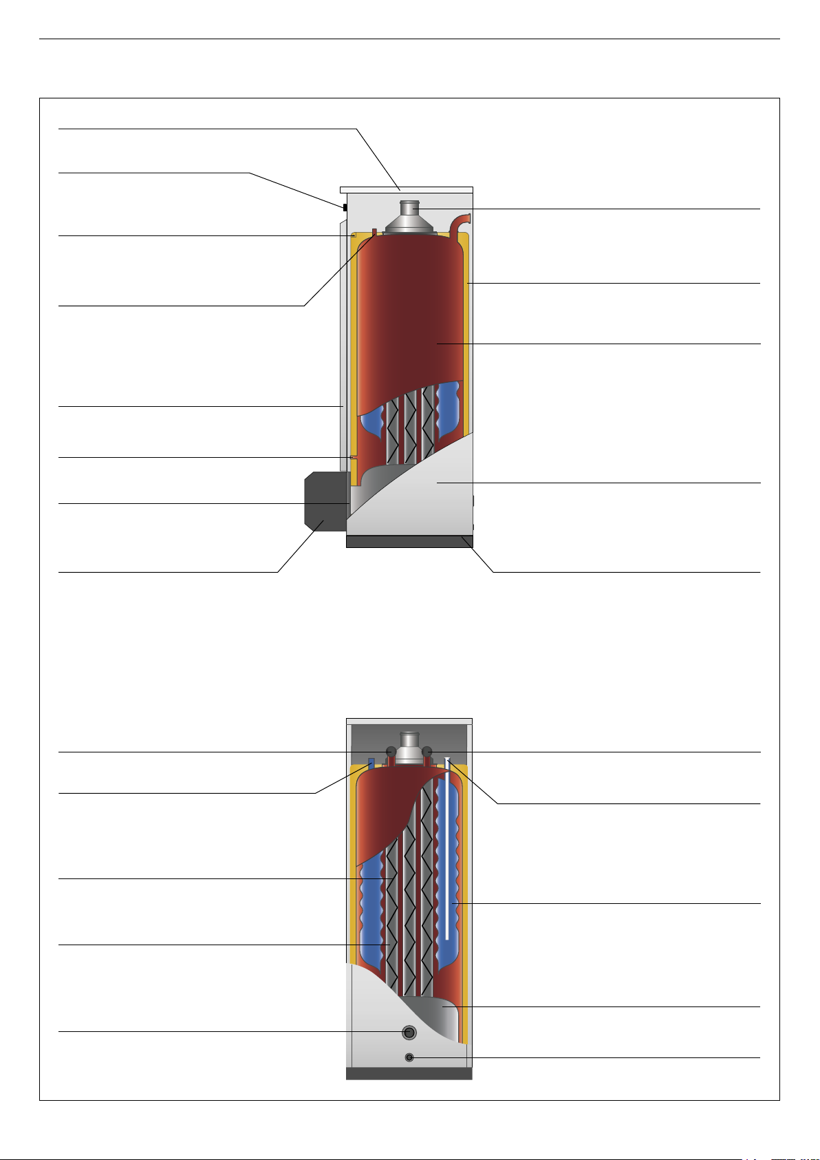
INTRODUCTION
Detachable casing cover (access to baffles)
Heating out
Domestic hot water outlet
Flue ways
Baffles
Heating return
Heating return
Domestic cold water inlet
Combustion chamber
Boiler drain cock
Inner annular tank containing
a domestic hot water
Polyurethane foam insulation
Outer body containing the primary water
Base
Detachable front panel
Burner cover
Manual reset high limit thermostat (103°C)
Control panel
Side casing
Burner chamber plate
Control thermostat bulb
Bulb of the thermal reset high
limit thermostat (95°C)
Chimney reducing pipe
Page 6
EN • 6
INSTRUCTIONS
We recommend that you have your system serviced
each year by a qualified engineer.
Starting the burner:
In normal operation the burner starts automatically if
the temperature of the boiler is below setpoint.
Before carrying out any work on the boiler, isolate
it from the electrical supply at the switch on the
external control box.
Also move the main switch on the control panel to
“OFF”.
YOU SHOULD FAMILIARISE YOURSELF
WITH THE CONTROL PANEL
1 - Control thermostat
If the boiler is being used to generate hot water only, the boiler
temperature can be set to between 60 and 90°C. If the boiler
is being used for hot water and heating, then the boiler’s control
thermostat should normally be set to 80°C to guarantee optimum
operating conditions.
2 - Main switch
This switch is used to start and stop the boiler
3 - Summer/Winter switch
Switches ON and OFF the heating pump.
4 - Thermometer
The thermometer shows the boiler temperature in the heating
circuit. This temperature should not exceed 90°C. If it does,
stop the boiler and check the set tings on the thermostat. If the
problem persists, contact your installer for advice.
5 - ACV climatic controller (optional)
Refer to the instructions supplied with the controller if you have
this option.
4
3
51 2
PRESSURE IN THE HEATING SYSTEM
The Central Heating pressure must be minimum 1 bar and must
be periodically checked by the end user.
Make sure that the appliance is powered off when filling the
system. To do this, turn the on/off switch. For more information,
please ask your installer when the system is delivered. A safety
valve is provided underneath the appliance. If the system pressure
exceeds 3 bars, this valve opens and drains the water from the
system. In this case, please contact your installer.
The water escaping from the safety valve
can be extremely hot and cause very
serious burns.
Page 7
EN • 7
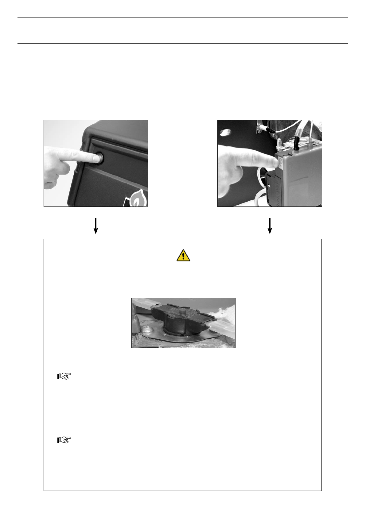
BURNER SHUTDOWN
If the oil burner is not working:
1. The burner indicator lamp lights.
2. Press the burner reset button on the burner. Now switch
off the boiler for a few seconds at the main switch and then
restart it.
If the gas burner is not working:
1. Remove the protective burner cover.
2. The reset but ton lamp is lit.
3. Press the reset but ton to start the burner. Now switch off the
boiler for a few seconds at the main switch and then restart it.
If the oil or gas burner does not operate, isolate the boiler’s electrical supply at the switch
on the external control box before removing the front panel of the casing, for press the
manual reset high limit thermostat on the top of the boiler
Manual reset high
limit thermostat
Wait until the boiler temperature drops to below 60°C, then refit the front panel
of the casing.
If the problem persists, please contact your installer for advice.
Starting the burner.
In normal operation the burner starts automatically if the temperature of the boiler is below setpoint.
To ensure that your system operates correctly, please have it serviced annually by a
qualified engineer; servicing should be done before the start of the heating season.
INSTRUCTIONS
Page 8

EN • 8
TECHNICAL CHARACTERISTICS
DOMESTIC HOT WATER OUTPUT DATA
25
F25 / G25
35
F35 / G35
45
F45 / G45
55
F55 / G55
Operating conditions at 80°C
Peak flow at 40°C [ΔT = 30°C] L/10’ 268 285 316 362
Peak flow at 40°C [ΔT = 30°C] L/60’ 806 1035 1284 1533
Constant flow at 40°C [ΔT = 30°C] L/h 645 900 1161 1405
Tank refill time at 60°C
Initial heating time minutes 32 29 16 16
After drawoff of 140 L at 45°C minutes 15 11 9 7
GENERAL CHARACTERISTICS
25
F25 / G25
35
F35 / G35
45
F45 / G45
55
F55 / G55
Total capacity L 157 178 132 162
Heating circuit capacity L 83 104 70 82
Heating connection Ø 1” 1” 1” 1”
DHW connection Ø 3/4” 3/4” 3/4” 3/4”
Water tank heat exchanger surface m
2
1,59 1,59 1,99 2,46
BOILERS WITHOUT BURNER 25 35 45 55
Input kW 25 / 33 33 / 45 42 / 61 50 / 69
Output kW 22 / 29 29 / 40 38 / 54 45 / 62
Heat losses [60°C] % 1,36 / 1,0 1,0 / 0,79 0,8 / 0,56 0,75 / 0,6
DIMENSIONS 25 35 45 55 F25 F35 F45 F55 G25 G35 G45 G55
A [mm] 1497 1697 1497 1697 1497 1697 1497 1697 1497 1697 1497 1697
B [mm] 130 130 150 150 130 130 150 150 130 130 150 150
C [mm] 360 360 390 390 360 360 390 390 360 360 390 390
D [mm] 565 565 565 565 818 818 818 848 755 755 755 755
Weight when empty [kg] 145 156 168 200 157 168 180 212 159 170 182 214
GENERAL
The appliances are supplied fully assembled, tested and packed
standing on a timber base with impact protection strips and
rapped in heat-shrunk plastic film. When the appliance arrives,
remove the packaging and check that no par ts have been
damaged during shipment. Refer to the dimensions and weights
listed below for handling purposes:
OPERATING CONDITION LIMITS
Maximum service pressure (tank filled with water)
- Heating circuit: 3 bar
- DHW circuit: 10 bar
Test pressure (tank filled with water)
- Heating circuit: 4,5 bar
- DHW circuit: 13 bar
Operating temperature
- Maximum temperature: 90°C
Water quality
• Chlorides: < 150 mg/l (304 Stainless steel)
< 2.000 mg/l (Duplex)
• 6 ≤ ph ≤ 8
570
B
200
C
542
D
A
276
Page 9

EN • 9
Chimney connector type: B23
The chimney must be connected to the boiler by means of a metal
pipe rising at an angle from the boiler to the chimney. It must be
easily removable in order to give access to the flue pipes when
servicing the boiler. A draught regulator must be installed on the
chimney in order to stabilise negative pressure.
The high efficiency of our boilers means that the flue
gases exit at low temperature. The attendant risk of
condensation may cause damage to some chimneys.
To avoid this risk we strongly advise that you line the
chimney.
Please contact your installer for further information
about chimney lining.
A. High level ventilation
B. Low level ventilation
C. Draught stabiliser
D. Flame inspection window
E. Height of lined chimney
F. Chimney diameter
INSTALLATION
A
B
F
D
C
E
BOILER ROOM
Important
• Never obstruct the ventilation.
• Do not store inflammable products in the boiler room.
• Avoid storing corrosive products such as paint, solvents, chlorine,
salt, soap or other cleaning products near the boiler.
Accessibility
The boiler room should be large enough to allow easy access to the
boiler. Minimum clearances around the boiler:
• To the front 500 mm
• To the rear 150 mm
• To the sides 100 mm
• Above 700 mm
Base
The base on which the boiler will be mounted must be made from
non-combustible materials.
Ventilation
The boiler room must have both low and high level ventilation.
By way of information, the table below gives the minimum
ventilation requirements according to Belgian regulations.
The user must ensure that his boiler room ventilation complies
with local regulations.
CHIMNEY CONNECTION
Important:
The boiler must be installed by a qualified engineer
in accordance with the local standards and codes of
practice.
The diameter of the chimney must not be less than the
diameter of the boiler’s chimney reducer.
Ventilation
25
F25
35
F35
45
F45
55
F55 G25 G35 G45 G55
Fresh air supply minimum m3/h 50 / 66 66 / 99 84 / 122 100 / 138 45 63 81 99
High level ventilation [A] dm2 2 2 2 2 1,5 1,5 1,5 1,5
Low level ventilation [B] dm2 1,5 1,5 1,5 1,5 / 2,1 1,5 1,5 1,5 1,7
Draught stabiliser [C] Ø 130 130 150 150 130 130 150 150
Chimney
25
F25
35
F35
45
F45
55
F55 G25 G35 G45 G55
E = 5 m Ø min. F mm 158 / 182 182 / 213 208 / 248 226 / 266 160 189 215 236
E = 10 m Ø min. F mm 133 / 153 153 / 179 175 / 209 190 / 223 135 159 181 199
E = 15 m Ø min. F mm 130 / 138 138 / 162 158 / 188 172 / 202 130 143 163 179
N.B.:
The figures for (B) and (C) only apply to type B23 connectors.
The above table is shown by way of indication only as regulations vary from country to country.
Page 10
EN • 10
INSTALLATION
8 8
4
3
1
2
5
6
9
7
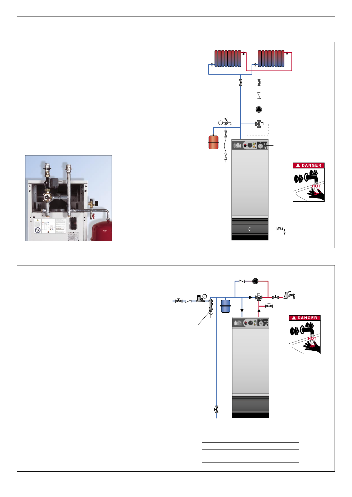
HEATING SYSTEM CONNECTION
TYPICAL SINGLE CIRCUIT CONFIGURATION
1. 3-way motorised mixer valve.
2. Safety valve calibrated to 3 bar, with pressure gauge.
3. Pump.
4. Check valve.
5. System filling valve.
6. Expansion vessel.
7. Controller ACV 13.00 (see Controller Kit on page 11)
8. Isolating valve, heating system.
9. Drain cock.
DRAIN
The drain cock and safety valve must be connected to the sewer.
DOMESTIC HOT WATER CONNECTION
TYPICAL CIRCUIT WITH THERMOSTAT VALVE
1. Safety group
2. Pressure reducing valve
3. Thermostatic mixer
4. Hot water pump
5. Check valve
6. Hot water expansion vessel
7. Cold water supply tap
8. Drawoff tap
9. Drain cock
10. Air vent
11. Isolating valve
PRESSURE REDUCING VALVE
If the mains water pressure exceeds 6 bar, a pressure reducing
valve calibrated to 4.5 bar must be installed.
SAFETY GROUP
The safety group of the water tank must be approved by ACV and
calibrated to 7 bar; the group’s valve discharge must be connected
to the sewer.
HOT WATER EXPANSION VESSEL
Installing a hot water expansion vessel will prevent any risk of excess
pressure due to water hammer or pressure fluctuations.
HOT WATER CIRCULATION
If the water tank is a long way from the point of use, installing a
closed recirculation circuit can ensure a faster hot water drawoff
at any time.
ACV HYDRAULIC KIT
ACV can supply an optional
pre-assembled water kit.
This kit comprises:
• A pump;
• A 3-way manual valve. This valve can be
motorised if required;
• Connection pipes that can be used to
connect a second heating circuit;
• Two isolating valves;
• Connectors for the right or left hand
mounting of the expansion vessel, the
safety valve with pressure gauge and the
filling valve. The expansion vessel is not
included.
4
5
3
11
8
10
6
9
7
5
2
1
Optional accessories
Safety group Ø 3/4”
Pressure reducing valve Ø 3/4”
Thermostatic mixer Ø 3/4”
Expansion vessel 5 litres
IMPORTANT
As a safety
measure, we
strongly advise
the installation of
a thermostatic
mixer to prevent
any risk of
burning to
persons.
Page 11

EN • 11
INSTALLATION
CONTROLLER KITS [OPTIONAL]
KIT 1: ACV 13.00 / BASIC
This basic kit is used to control the hot water circuit outlet
temperature as a function of ambient conditions.
It comprises: a temperature controller with analog clock, a
surfacemounted primary water temperature sensor (-30/130°C),
an outdoor sensor (-30/50°C), a servomotor SSY 319 230 V 3-pin and an intermediate socket.
KIT 2: ACV 13.00 / STANDARD
This basic kit is used to control the hot water circuit outlet
temperature as a function of ambient conditions.
It comprises: a temperature controller with analog clock, a
surfacemounted primary water temperature sensor (-30/130°C),
an outdoor sensor (-30/50°C), a servomotor SQY 349 230 V 3-pin and an intermediate socket.
CIRCUIT DIAGRAM OF ACV CONTROL KITS
B2. Temperature sensor
B9. Outdoor sensor
B5. Analog/digital room sensor
P1. Pump
Y1/Y2/N. Servomotor (SSY 319 or SQK 349)
bl. Blue N
n/z. Black Y2
br. Brown Y1
Please contact your installer for further details about
this.
20 19 18 17 16 15 14 13 12 11 10 9 8 7 6 5 4 3 2 1
20 19 18 17 16 15 14 13 12 11 10 9 8 7 6 5 4 3 2
1
bl
bk br
SSY 319 / SQK 349
QAAD50
(QAAD70)
QAC32 QAD2
2
P1 B5 B9 B3 B2
P1Y1Y2N B5 B9 B3 B
2
OIL SUPPLY
INSTALLATION WITHOUT RETURN INSTALLATION WITH RETURN
H
H
Height [H] Ø int. 8 mm [L] Ø int. 10 mm [L]
0,5 m 10 m 20 m
1,0 m 20 m 40 m
1,5 m 40 m 80 m
2,0 m 60 m 100 m
Height [H] Ø int. 8 mm [L] Ø int. 10 mm [L]
0,0 m 35 m 100 m
0,5 m 30 m 100 m
1,0 m 25 m 100 m
1,5 m 20 m 90 m
2,0 m 15 m 70 m
2,5 m 8 m 30 m
3,5 m 6 m 20 m
Page 12
EN • 12
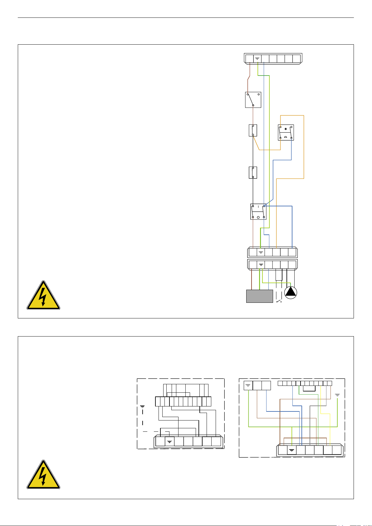
ELECTRICAL CONNECTIONS
ELECTRICAL BOILER CONNECTION
PRINCIPLE OF SUPPLY
The boiler operates on a single-phase supply of 230 V/50 Hz.
You should install a control box with main switch and 6 A fuses
externally to the boiler to allow the boiler to be isolated from the
supply for servicing and repairs.
STATUTORY COMPLIANCE
The installation must comply with your local standards and codes
of practice.
SAFETY
The stainless steel water tank must be provided with a separate
earth.
BOILER WIRING
1. Control thermostat [60/90°C]
2. Main switch
3. Summer / Winter switch
4. Manual reset high limit thermostat [103°C max.]
5. Power supply to boiler
6. Heating pump connection
7. Burner connection [7-pin plug]
8. Room thermostat [optional]
9. Thermal reset high limit thermostat [95°C]
B. Blue
Br. Brown
Bk. Black
Or. Orange
Y/Gr. Yellow / Green
The boiler must be isolated from
the electrical supply before any
work is carried out on it.
1
2
C
L1
L1
N T1 T
2
N T1 T
2S3S3
S3 B4
NT1T2
L1
1
4
9
2
3
7
5 8
6
230V ~ 50 Hz
6A
Br Bk
Bk Br
Or
Y/Gr
B
Br
B
Or
B
Y/Gr
B
Br
B
Y/Gr
Br
Or
Or
B
Or
ELECTRICAL BURNERS CONNECTION
PH. Phase
N. Neutral
M. Motor
VM1. Magnetic valve 1
VM2. Magnetic valve 2
PF. Oil preheating
T. Ignition transformer
AL. Alarm
CF. Photoelectric cell
B. Blue
Br. Brown
Bk. Black
G. Grey
Gr. Green
Y. Yellow
Y/Gr. Yellow / Green
The boiler must be isolated from
the electrical supply before any
work is carried out on it.
1 2 3 4 5 6 7 8 9 10 1112
S3 B4
N T
2
T1
L1
PH
PF
VM
2
VM1
T
AL
CF
N
M
L1 N
1 2 3 4 5 6 7 8 9 1011 12
S3 B4
N T
2
T1
L1
Br
B
Y/Gr
Y/Gr
B
Gr
Y
G
Br
Bk
Br
Br
Gr
Y
Br Br
Y/Gr
B
G
ELECTRICAL CONNECTION
BM R 31 - BM R 51 - BM 101
ELECTRICAL CONNECTION
BG 2000-S
Page 13
EN • 13
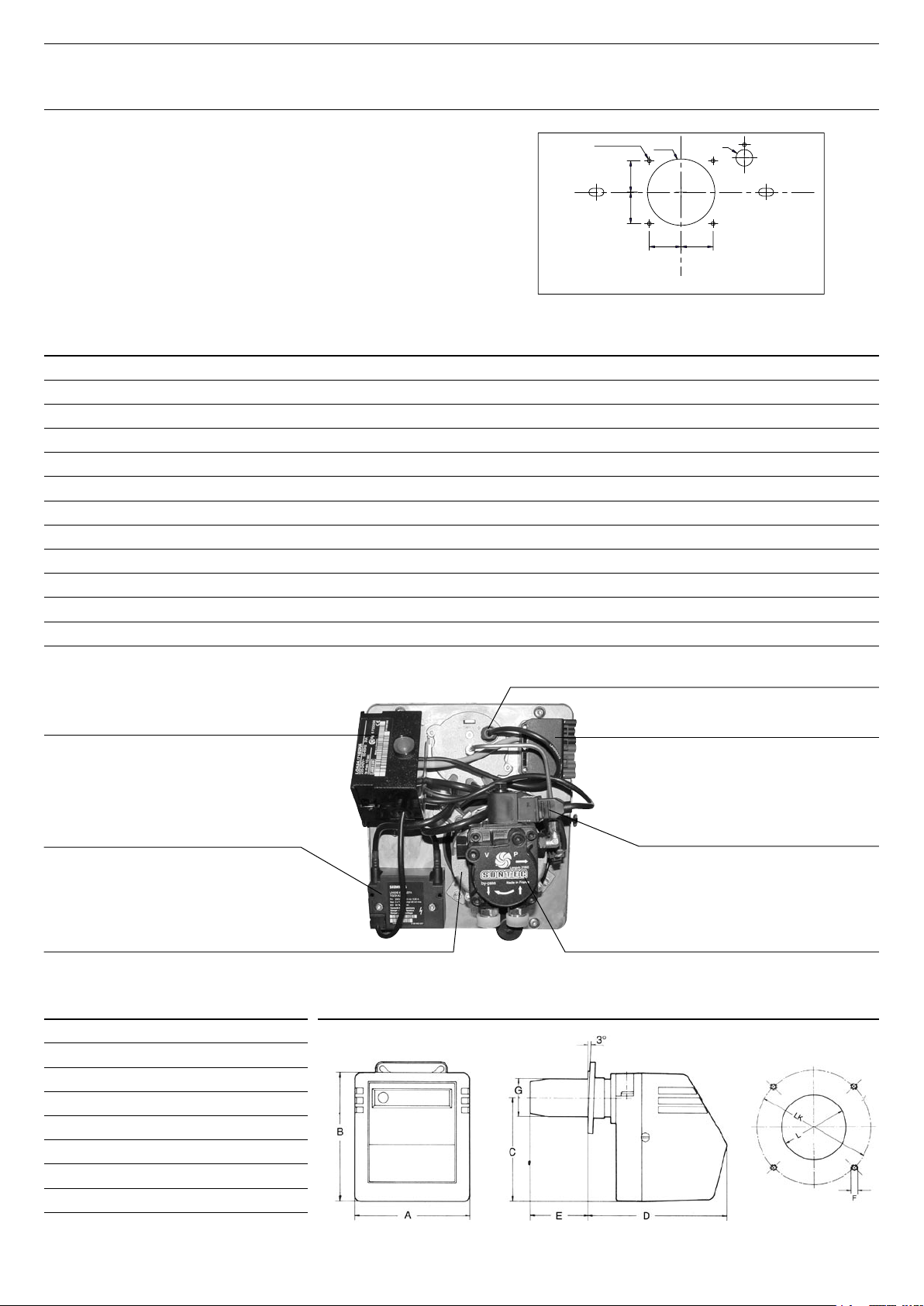
OIL BURNER CHARACTERISTICS
Relay
Burner connector
High viltage transformer
Solenoid valve
Motor
Photoelectric sell
Oil pump
OIL BURNER DESCRIPTION
To fit out our Delta performance Oil boiler we needed a really high
performance burner to give perfect combustion.
We opted to use the brand new technology of the ACV BM R 31,
BM R 51 y BM 101 burners.
Chamber plate (oil)
The chamber plate has 4 screws (M 8 x 20 mm) for the fixing of
the burner. It is protected from the radiation of the flame by an
insulation blanket.
SETTING OIL BURNER PARAMETERS F25 F35 F45 F55
Burner BM R 31 BM R 31 BM R 51 BM 101
Output kW 12 / 48 12 / 48 42 / 60 55 / 130
Electrical power W 150 150 150 185
Nozzle gal/h 0,6 0,75 0,85 1,50
Nozzle angle 60° 60° 60° B 60° B
Oil flow rate kg/h 2,18 2,84 3,60 5,76
Pump pressure bar 11,2 12,0 15,0 10,0
Flue gas index 0,6 0,3 0,4 0,5
Air flap setting 4,5 4,8 4,5 5,0
Combustion head setting 1 2 - 3 4 - 5 4 - 5
Flue pressure drop mbar 0,02 / 0,09 0,08 / 0,09 0,01 / 0,08 0,02 / 0,05
Weight kg 12 12 12 14
Ø112
Ø28
4 x Ø6.5 (M8)
53
53
53 53
BM R 31
BM R 51 BM 101
A mm 240 260
B mm 270 300
C mm 215 250
D mm 280 310
E mm 60 - 130 60 - 150
F M 8 M 8
G mm 80 90
L
Ø
85 95
LK Ø 140 - 165 125 - 180
Page 14
EN • 14
GAS BURNER CHARACTERISTICS
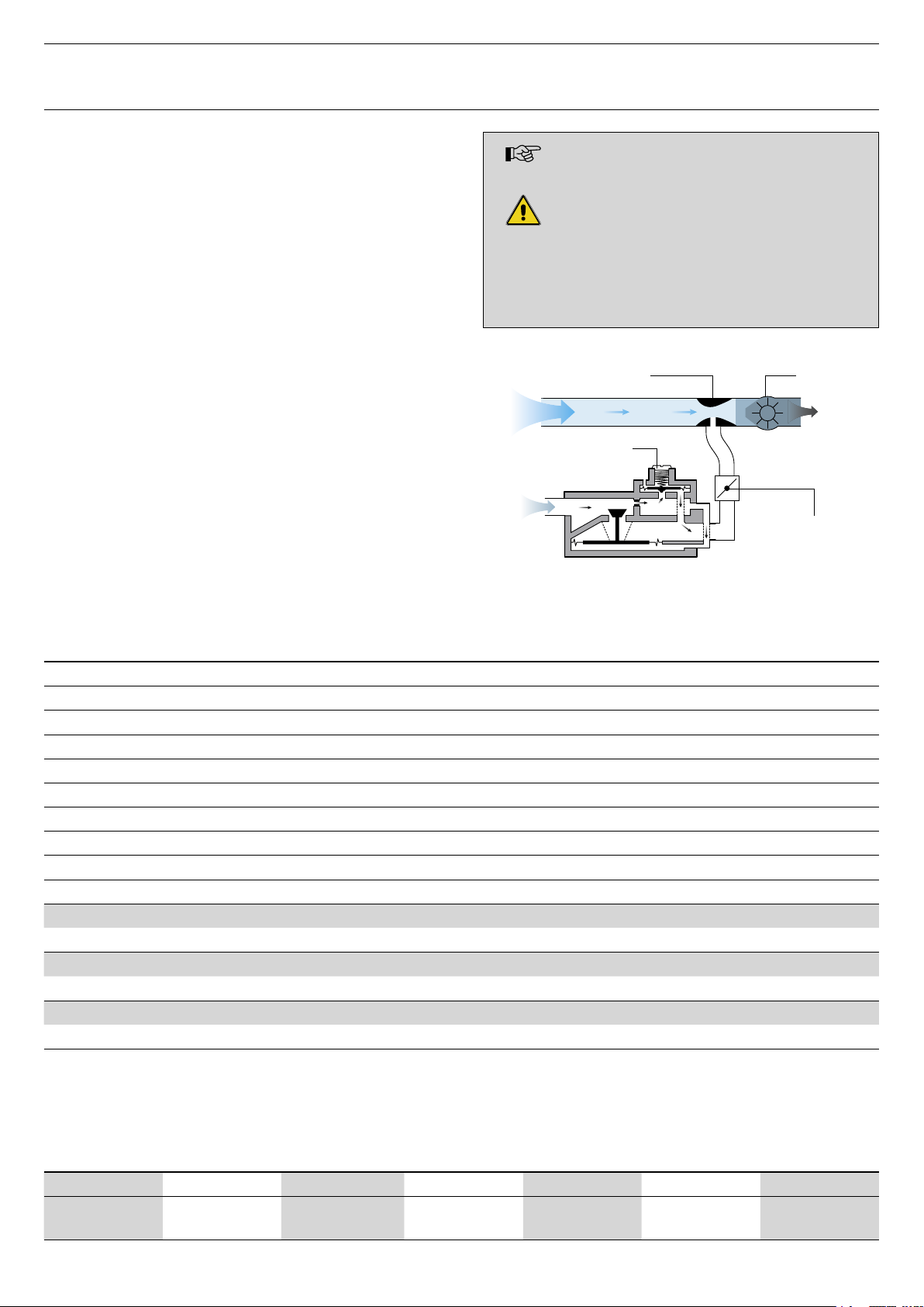
ACV BG 2000-S AIR/GAS PREMIX GAS BURNERS
The air/gas premix BG 2000-S burner is fitted with a Honeywell
gas valve, a venturi tube and an electrical control relay. The gas
valve has been specially developed for low NOx air/gas premix
burners with automatic lighting and flame detection by ionisation.
The pressure at the gas valve outlet is equal to the air pressure at
the neck of the venturi tube, reduced as the offset is adjusted. The
fan sucks in the combustion air through the venturi tube which the
gas inlet leads into. As it goes through, the air creates a vacuum
to the right of the neck of the venturi tube and sucks in the gas at
the venturi tube outlet. A perfect air/gas mix then goes through the
fan and then goes on towards the ramp.
The electrical control relay built into the gas valve ensures that the
flame on the burner is properly it and controlled.
This principle guarantees silent and totally safe operation:
• If there is not enough air, the vacuum in the venturi tube drops,
the gas flow is reduced, the flame goes out and the gas valve is
closed. The burner is locked out.
• If there is any restriction in the discharging of the burnt gases,
the air flow drops and this leads to the same reactions as those
described above leading to the burner being shut down, locked
out.
SETTING OIL BURNER PARAMETERS G25 G35 G45 G55
Burner BG 2000-S/25 BG 2000-S/35 BG 2000-S/45 BG 2000-S/55
Input kW 25 34,9 45 55
Output kW 22,45 31,35 40,5 49
Combustion efficiency - natural gas % 91,7 91,5 92,4 92
CO2 natural gas % 9,1 9,0 8,9 9,0
CO2 propane % 11,0 / 11,2 11,0 / 11,2 11,0 / 11,2 11,0 / 11,2
Net T° of burnt gases °C 170 173 153 165
Maintenance loss at 60°C of rate value % 1,36 1,0 0,8 0,7
Gas connection [female] Ø 3/4” 3/4” 3/4” 3/4”
Weight Kg 14 14 14 14
Gas G20 - 20 mbar [ I2E(S)B - I2Er - I2H - I2ELL - I2 E ]
Flow m3/h 2,65 3,70 4,76 5,8
Gas G25 - 20 mbar [ I2ELL ] - 25 mbar [ I2L ]
Flow m3/h 3,07 4,3 5,52 7,98
Gas G31 - 30 / 37 / 50 mbar [ I3P ]
Flow m3/h 1,02 1,43 1,84 2,25
N.B. : • The burners are preset in our factory for use with natural gas (equivalent to G20)
• An adjustement of the CO2 % is not allowed in Belgium. I 2E(S)B
The BG 2000-S burner is factory preset to
natural gas.
Conversion to propane:
Prohibited in Belgium.
Conversion kit enclosed with the burner comprising:
- Gate disk(s)
- Rating plate(s).
- Settings sticker.
- Assembly instructions.
Venturi Fan
Air / Gas
mixture
Air
Gas
Offset
adjuster screw
Gas flow adjuster
screw [CO2]
GAS CATEGORIES
I2Er I2E(S)B I2H I3P I2L I2ELL I2E
FR BE
AT - DK - ES - UK
IT - PT - IE - SE
BE - FR - ES
UK - PT - IE
NL DE LU
Page 15

EN • 15
GAS BURNER CHARACTERISTICS
Ignition electrode
Burner reset
Female gas connector Ø 3/4”
Ionisation electrode
Venturi
Fan
Burner chamber plate insulation
Burner chamber plate sealing cord
Gas valve
Burner chamber plate
Flame inspection window
Burner tube
Potentiometer setting
Electrical burner connector
Ignition cable
Ionisation cable
Control/monitoring relay
Page 16

EN • 16
FILLING THE HOT WATER AND HEATING CIRCUITS
IMPORTANT
It is essential that the water tank is under pressure
before the heating circuit is filled.
1. Fill the hot water circuit and pressurise it.
2. Fill the heating circuit - do not exceed a pressure of 2 bar.
3. Vent the air in the top of the boiler.
4. Once you have vented the system, return the pressure to static
pressure plus 0.5 bar.
Height of the heating system:
• 10 m ➠ heating circuit pressure = 1.5 bar
• 15 m ➠ heating circuit pressure = 2 bar
USING THE BOILER FOR THE FIRST TIME
1. Check the gas or oil supply connection and ensure that it is free
from leaks.
2. Check the electrical connection to the boiler and the boiler
room ventilation, and ensure that the flue gas discharge pipes
and the burner chamber plate are properly gas tight.
3. Set the boiler thermostat to between 60 and 90°C.
4. Move the Summer/Winter switch to the required position.
5. Move the main switch to “ON”.
6. Carry out the necessary venting operations, measurements and
settings.
RECOMMENDATION
ACV recommends that you have the boiler serviced at least once
a year. Boiler servicing and checking must be carried out by a
qualified engineer.
MAINTENANCE OF BOILER
1. Isolate the boiler from the electrical supply at the switch on the
external control box, and close the gas or oil supply valve.
2. Move the main switch on the control panel to “OFF”.
3. Remove the chimney flue (G) to free the top of the boiler.
4. Remove the jacket top (A) and lift off the flue reducer (B).
5. Remove the baffles (C) from the flue ways (D) and clean them.
Replace these items if worn.
6. Remove the burner cover and burner [E].
7. Brush the flue ways (D).
8. Clean the combustion chamber (F) and the burner.
9. Check the condition of the seal on the burner chamber plate [H].
MAINTENANCE OF BURNER
See the technical and maintenance manual of the burner.
MAINTENANCE OF SAFETY EQUIPMENT
- Check that all thermostats and safety devices operate correctly:
boiler thermostat, thermal reset high limit thermostat and manual
reset high limit thermostat.
- Check the safety valves in both the heating circuit and the hot
water circuit.
COMMISSIONING AND MAINTENANCE
DRAINING THE BOILER
The water draining from the drain cock is very
hot and can cause serious burns. Keep all
persons away from running hot water.
Draining the heating circuit
1. Move the main switch on the control panel to “OFF”, isolate the
boiler from the electrical supply at the switch on the external
control box and close the gas or oil supply valve.
2. Close the isolating valves (8) in the heating circuit.
3. Connect a flexible tube to the drain cock (9).
4. Open the drain cock (9) to drain the heating circuit.
Draining the hot water circuit
1. Move the main switch on the control panel to “OFF”, isolate the
boiler from the electrical supply at the switch on the external
control box and close the gas or oil supply valve.
2. Release the pressure in the heating circuit until the pressure
gauge reads zero.
3. Close the tap (7) and the isolating valve (11).
4. Open the drain cock (9) and air vent (10) (first 9 then 10).
5. Allow the hot water circuit to discharge to the drain.
The drain cock (9) must be at ground level for the
circuit to drain fully.
Water escaping from the safety valve or safety
group can be extremely hot and cause very
serious burns.
Page 17

EN • 17
COMMISSIONING AND MAINTENANCE
8 8
4
3
1
2
5
6
9
7
4
5
3
11
8
10
6
9
7
5
2
1
F
D
C
E
A
B
G
H
Page 18

EN • 18
Page 19

A09
A05
A02
A03
A08
N° 25 - F25 G25 35 - F35 G35 45 - F45 G45 55 - F55 G55
A01
30537054 30537054 30537055 30537055 30537389 30537389 30537227 30537227
A02
21473338 21473338 21473339 21473339 21473338 21473338 21473339 21473339
A03
21472338 21472338 21472339 21472339 21472338 21472338 21472339 21472339
A04
21471338 21471338 21471339 21471339 21471338 21471338 21471339 21471339
A05
21474338 21474338 21474339 21474339 21474338 21474338 21474339 21474339
A06
21475338 21475338 21475338 21475338 21475338 21475338 21475338 21475338
A07
21478338 21478338 21478338 21478338 21478338 21478338 21478338 21478338
A08
21476339 21476338 21476339 21476338 21476339 21476338 21476339 21476338
A09
21477338 21477338 21477338 21477338 21477338 21477338 21477338 21477338
A10
21423026 2147P263 21423026 2147P263 21423026 2147P263 21423026 2147P263
A07
A06
A04
A10
A01
Page 20

25 - F25 - G25 35 - F35 - G35 45 - F45 - G45 55 - F55 - G55
24614093 24614093 24614093 24614093
54766016 54766016 54766016 54766016
54766017 54766017 54766017 54766017
54442045 54442045 54442045 54442045
54764021 54764021 54764021 54764021
54763007 54763007 54763007 54763007
54322000 54322000 54322000 54322000
54764010 54764010 54764010 54764010
54428129 54428129 54428129 54428129
49410045 49410045 49410045 49410039
Page 21

25 - F25 - G25 35 - F35 - G35 45 - F45 - G45 55 - F55 - G55
50423337 50423337 - -
- - 507F3033 507F3033
- - 557A0016 557A0016
507F2005 507F2005 507F2005 507F2005
51305000 51305000 51305000 51305000
55426001 55426001 55426001 55426001
63438001 63438001 63438001 63438001
47438008 47438008 47438008 47438008
47405004 47405004 47405004 47405004
47405005 47405005 47405005 47405005
Page 22

F25 F35 F45 F55
BM R 31
237E0009 237E0009 - -
BM R 51
- - 23860600 -
BM 101
- - - 23860200
G25 G35 G45 G55
BG 2000-S/25
237D0063 - - -
BG 2000-S/35
- 237D0066 - -
BG 2000-S/45
- - 237G0065 -
BG 2000-S/55
- - - 237D0013
Page 23

excellence in hot water
INTERNATIONAL
ACV international n.v
KERKPLEIN, 39
B-1601 RUISBROEK - BELGIUM
TEL.: +32 2 334 82 20
FAX: +32 2 378 16 49
E-MAIL: international.info@acv-world.com
BELGIUM
ACV BELGIUM nv/sa
KERKPLEIN, 39
B-1601 RUISBROEK-BELGIUM
TEL.: +32 2 334 82 40
FAX: +32 2 334 82 59
E-MAIL: belgium.info@acv-world.com
CHILE
ALBIN TROTTER Y ACV LTDA
SAN PABLO 3800
QUINTA NORMAL - SANTIAGO - CHILE
TEL.:+56 2 772 01 69
FAX:+56 2 772 92 62/63
E-MAIL: chile.info@acv-world.com
CZECH REPUBLIC
ACV CR SPOL. s.r.o
NA KRECKU 365
CR-109 04 PRAHA 10 - CZECH REPUBLIC
TEL.:+420 2 720 83 341
FAX:+420 2 720 83 343
E-MAIL: ceskarepublika.info@acv-world.com
DEUTSCHLAND
ACV WÄRMETECHNIK GMBH & CO KG
GEWERBEGEBIET GARTENSTRASSE
D-08132 MÜLSEN OT. JACOB - DEUTSCHLAND
TEL.:+49 37601 311 30
FAX:+49 37601 311 31
E-MAIL: deutschland.info@acv-world.com
ESPAÑA
ACV ESPAÑA
C/DE LA TEIXIDORA, 76
POL. IND. LES HORTES
E-08302 MATARÓ - ESPANA
TEL.:+34 93 759 54 51
FAX:+34 93 759 34 98
E-MAIL: spain.info@acv-world.com
FRANCE
ACV FRANCE sa
31, RUE AMPERE - Z.I MI - PLAINE
F-69680 CHASSIEU - FRANCE
TEL.:+33 4 72 47 07 76
FAX:+33 4 72 47 08 72
E-MAIL: france.info@acv-world.com
ITALIA
ACV ITALIA
VIA PANA 92
I-48018 FAENZA (RA) - ITALIA
TEL.:+39 0546 64 61 44
FAX:+39 0546 64 61 50
E-MAIL: italia.info@acv-world.com
NEDERLAND
ACV NEDERLAND bv
POSTBUS 350
NL-2980 AJ RIDDERKERK - NEDERLAND
TEL.:+31 180 42 10 55
FAX:+31 180 41 58 02
E-MAIL: nederland.info@acv-world.com
POLAND
ACV POLSKA sp. z.o.o.
UL.WITOSA 3
87 - 800 WŁOCŁAWEK - POLAND
TEL.:+48 54 412 56 00
FAX:+48 54 412 56 01
E-MAIL: polska.info@acv-world.com
PORTUGAL
BOILERNOX LDA
RUA OUTEIRO DO POMAR
CASAL DO CEGO, FRACÇÃO C,
PAVILHÃO 3 - MARRAZES
2400-402 LEIRIA - PORTUGAL
TEL.:+351 244 837 239/40
FAX:+351 244 823 758
E-MAIL: boilernox@mail.telepac.pt
RUSSIA
ACV RUSSIA
1/9, MALYI KISELNYI
103031 MOSCOW - RUSSIA
TEL.:+7 095 928 48 02 / +7 095 921 89 79
FAX:+7 095 928 08 77
E-MAIL: russia.info@acv-world.com
SLOVAK REPUBLIC
ACV SLOVAKIA s.r.o.
PLUHOVÁ 49
831 04 BRATISLAVA - SLOVAK REPUBLIC
TEL.:+421 2 444 62 276
FAX:+421 2 444 62 275
E-MAIL: slovakia.info@acv-world.com
SLOVENIA
ACV D.O.O. SLOVENIA
OPEKARNA 22b
1420 TRBOVLJE - SLOVENIA
TEL.:+386 356 32 830
FAX:+ 386 356 32 831
E-MAIL: slovenia.info@acv-world.com
UK
ACV UK Ltd
ST. DAVID’S BUSINESS PARK
DALGETY BAY - FIFE - KY11 9PF
TEL.:+44 1383 82 01 00
FAX:+44 1383 82 01 80
E-MAIL: uk.info@acv-world.com
USA
TRIANGLE TUBE PHASE III
FREEWAY CENTER - 1 TRIANGLE LANE
BLACKWOOD NJ 08012 - USA
TEL.:+1 856 228 8881
FAX:+1 856 228 3584
E-MAIL: sales@triangletube.com
ARGENTINA
TECNOPRACTICA
ALFEREZ BOUCHARD 4857
1605 CARAPACHAY - BUENOS AIRES
TEL.: +54 11 47 65 33 35
FAX: +54 11 47 65 43 07
E-MAIL: jchas@tecnopractica.com
AUSTRALIA
HUNT HEATING PTY LTD
10 GARDEN BOULEVARD
3172 VICTORIA - AUSTRALIA
TEL.: +61 3 9558 7077
FAX: +61 3 9558 7027
E-MAIL: enquiries@huntheat.com.au
BRAZIL
SIMETAL INDUSTRIA E COMERCIO
DE FERRAMENTAS LTDA
RUA GERSON ANDREIS 535
95112 - 130 CAXIAS DO SUL - BRAZIL
TEL.: +55 54 227 12 44
FAX: +55 54 227 12 26
E-MAIL: export@simetall.com.br
BULGARIA
PROXIMUS ENGINEERING LTD
7 BIAL KREM STR.
9010 VARNA - BULGARIA
TEL.:+359 52 500 070
FAX:+359 52 301 131
E-MAIL: info@proximus-bg.com
CHINA
BEIJING HUADIAN HT POWER TECHNOLOGY
DEVELOPMENT CO. LTD
ROOM B-912, TOWER B, COFCO PLAZA
N°. 8, JIANGUOMENNEI AVENUE
BEIJING 100005 - PEOPLE’S REPUBLIC OF CHINA
TEL.:+86 10 652 30 363/393 EXT 101
FAX:+86 10 652 27 071
E-MAIL: li.zheng@acv-world.com
SHANGHAI COOLTECH LTD
14/F E. CHINA MERCHANTS PLAZA
N°. 333 CHENGDU ROAD (N)
200041 SHANGHAI - CHINA
TEL.:+86 21 52 98 11 22 - 820
FAX:+86 21 52 98 13 58
E-MAIL: cooltech@cooltech.sh.cn
www.acv-world.com
DENMARK
VARMEHUSET
FRICHSVEJ 40 A
8600 SILKEBORG - DENMARK
TEL.:+45 86 82 63 55
FAX:+45 86 82 65 03
E-MAIL: vh@varmehuset.dk
ESTONIA
TERMOX AS
TAHE 112A
51013 TARTU - ESTONIA
TEL.:+372 736 73 39
FAX:+372 736 73 44
E-MAIL: termox@termox.ee
GREECE
ESTIAS
MARASLI STREET 7
54248 THESSALONIKI - GREECE
TEL.:+30 23 10 31 98 77 / +30 23 10 32 03 58
FAX:+30 23 10 31 97 22
E-MAIL: info@genikithermanseon.gr
ÎLE MAURICE
SOTRATECH
29, RUE MELDRUM
BEAU BASSIN - ÎLE MAURICE
TEL.:+230 46 76 970
FAX:+230 46 76 971
E-MAIL: stech@intnet.mu
LITHUANIA
UAB “GILIUS IR KO”
SAVARNORIU PR. 192
3000 KAUNAS - LITHUANIA
TEL.:+370 37 308 930
FAX:+370 37 308 932
MAROC
CASATHERM
PLACE EL YASSIR
20300 CASABLANCA - MAROC
TEL.:+212 22 40 15 23
FAX:+212 22 24 04 86
NEW ZEALAND
ENERGY PRODUCTS INTERNATIONAL
8/10 BELFAST PLACE
PO BOX 15058 HAMILTON - NEW ZEALAND
TEL.:+64 7 847 27 05
FAX:+64 7 847 42 22
E-MAIL: pmckenzie@tycoint.com
ÖSTERREICH
PROTHERM HEIZUNGSTECHNIK Gmbh
TRAUNUFERSTRASSE 113
4052 ANSFELDEN - ÖSTERREICH
TEL.:+43 7229 804 82
FAX:+43 7229 804 92
E-MAIL: protherm@nextra.at
ROMANIA
SC TRUST EURO THERM SA
D.N PIATRA NEAMT - ROMAN
km 2 C.P 5 O.P 3 jud. Neamt
5600 PIATRA NEAMT - ROMANIA
TEL.:+40 233 20 62 06
FAX:+40 233 20 62 00
E-MAIL: office@eurotherm.ro
TUNISIE
SO.CO.ME CHAUMAX
BOÎTE POSTALE N°44
1002 TUNIS - TUNISIE
TEL.:+216 71 78 15 91
FAX:+216 71 78 87 31
UKRAINE
UKRTEPLOSERVICE LTD
PR. LAGUTENKO 14
83086 DONETSK - UKRAINE
TEL.:+38 062 382 60 47/48
FAX:+38 062 335 16 89
 Loading...