

Page 1
INSTALLATION OPERATING AND
SERVICING INSTRUCTIONS
NOTICE D’INSTALLATION,
D’UTILISATION ET D’ENTRETIEN
GEBRUIKSHANDLEIDING EN
INSTALLATIEVOORSCHRIFT
delta
excellence in hot water
EN
NL
FR
delta
performance
performance
ventouse FV
30/09/2004 - 664Y1600
Page 2
INSTALLATION OPERATING AND SERVICING INSTRUCTIONS 1
delta
FV 35
:With ACV BMV1 oil burner
delta
FV 50
:With ACV BMV2 oil burner
NOTICE D’INSTALLATION, D’UTILISATION ET D’ENTRETIEN 13
delta
FV 35
:Avec brûleur fioul ACV BMV1
delta
FV 50
:Avec brûleur fioul ACV BMV2
GEBRUIKSHANDLEIDING EN INSTALATIEVOORSCHRIFT 25
delta
FV 35
: Met fuel brander ACV BMV1
delta
FV 50
: Met fuel brander ACV BMV2
NOTICIAS DE INSTALACIÓN, UTILIZACIÓN Y MANTENIMIENTO 37
delta
FV 35
: Con quemador de gasoil ACV BMV1
delta
FV 50
: Con quemador de gasoil ACV BMV2
INSTRUZIONI DELL’ INSTALLAZIONE, DELL’ USO E DI MANUTENZIONE 49
delta
FV 35
:Con bruciatore a gasolio ACV BMV1
delta
FV 50
:Con bruciatore a gasolio ACV BMV2
ANLEITUNG ZUR INSTALLATION, GEBRAUCH UND WARTUNG 61
delta
FV 35
:Mit Ölbrenner ACV BMV1
delta
FV 50
:Mit Ölbrenner ACV BMV2
EN
DE
IT
ES
NL
FR
Page 3
A B
E
D
C
C
z
6A
7
1
9
3
4
2
6
85
1 4 5
2 3
B
Y/Gr
Br
Br
Br
Or
Or
Y/Gr
Or
B
B
Br Br
B
B
B
Br
B
R
B
Y/Gr
Y/Gr
SSY 319 / SQK 349
P1 B5 B9 B3 B2
bk br
bl
QAAD50
(QAAD70)
QAC32 QAD22
20 19 18 17 16 15 14 13 12 11 10 9 8 7 6 5 4 3 2 1
230V-50 H
20 19 18 17 16 15 14 13 12 11 10 9 8 7 6 5 4 3 2
P1Y1Y2NB5B9B3B2
1
Page 4
H
F
I
J
G
7
3
10
11
8
4
5
6
9
5
2
1
9
5
6
2
1
3
8 8
4
7
H
H
Page 5
K L
M
N
B 23
C 13 / C 33
5
4
8
7
6
14
13
10
12
11
9
17
21
19
20
26
22
24
23
1 32
25
16
18
15
F
C13
A
B
C33
120
150 min.
E
C
D
C43
C13
2 m min.
Page 6
O
P
Q
R
W
Y/Gr
B
Br
B
Y/Gr
Br
Br
B
Bk
Y/Gr
Y/Gr
Bk
B
Br
B
Y/Gr
Br
B
21 4
6
5
9
8
7
10
16
15
13
3
14
12
11
A1
12 11 4 N 3 N 8 N 3 N 6 4 10 11
M
1~
T2 T1 N L1
B4 S3
T2 T1 N L1
B4 S3
X1
X2
ZMOHBV1QRD
Page 7
1
EN
INSTALLATION, OPERATING
AND SERVICING INSTRUCTIONS
FV 35
with ACV
BMV(K)1
oil burner
FV 50
with ACV
BMV(K)2
oil burner
performance
balanced flue
Page 8
2
EN
INTRODUCTION 2
Intended users of these instructions 2
Symbols 2
Applicable standards 2
Warnings 2
DESCRIPTION 3
Overview 3
Description of operation 3
Construction features 3
Boiler captions 3
TECHNICAL SPECIFICATION 4
General 4
Maximum operating conditions 4
Dimensions 4
Domestic hot water performance 5
General features 5
INSTALLATION 6
Boiler room 6
Chimney connections 6
Heating connections 7
Hot water connections 7
Controller kits 7
Electrical connection 8
Oil supply 8
BURNER FEATURES 9
ACV BMV1 and BMV2 oil burners 9
ACV BMV1 and BMV2 burner factory settings 9
ACV BMV1 and BMV2 burner captions 9
STARTUP 10
Filling the hot water and heating circuits 10
Commissioning ACV BMV1 and BMV2 burners 10
SERVICING 10
Recommendation 10
Servicing the boiler 10
Servicing the safety devices 10
Servicing the burner 10
Emptying the boiler 10
USER GUIDE 11
Using the boiler 11
Resetting ACV BMV1 and BMV2 burners 12
INTENDED USERS OF THESE INSTRUCTIONS
These instructions are intended for:
- specifying engineers
- installing engineers
- users
- servicing technicians
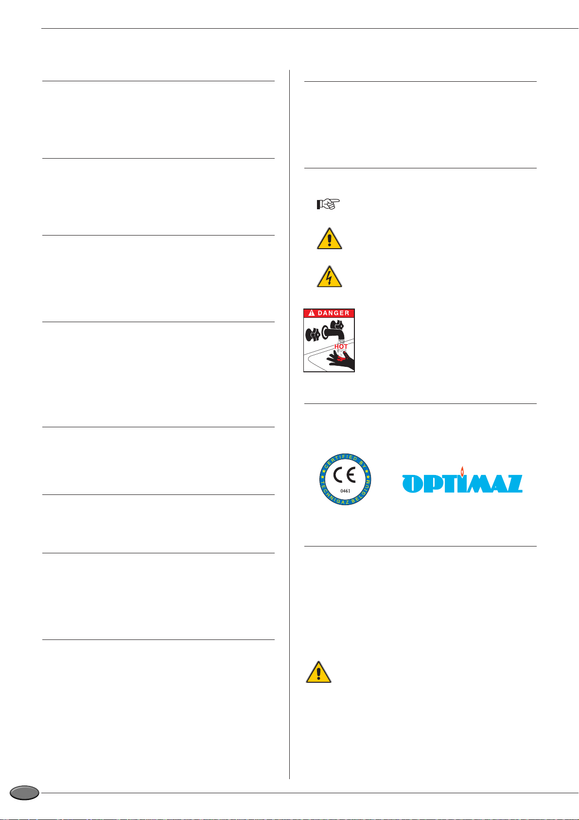
SYMBOLS
The following symbols are used in these instructions:
Essential instruction for operating the system
correctly.
Essential instruction for personal safety and
environmental protection.
Danger of electrocution.
Risk of burns.
APPLICABLE STANDARDS
The products have received the "CE" certificate of compliance with
standards of individual countries (European Directive 92/42/EEC,
"efficiency").These products also have the Belgian OPTIMAZ mark.
WARNINGS
These instructions are an integral part of the equipment to which
they refer and must be supplied to the user.
The product must be installed and serviced by qualified heating
engineers, in compliance with the prevailing standards.
ACV accepts no liability for any damage resulting from incorrect
installation or from the use of components or fittings not specified by
ACV.
Failure to observe instructions regarding tests
and test procedures can result in personal injury or
pollution risks.
Note:
ACV reserves the right to modify the technical specifications and
components of its products without prior notice.
INDEX INTRODUCTION
Page 9

3
EN
OVERVIEW
• Combination boiler (central heating and domestic hot water).
•TANK-IN-TANK indirect storage type domestic hot water production.
• Equipment required: a hydraulic connection kit for the heating
circuit (available as an option).
• The control panel comprises an on/off switch, adjustable
thermostat, thermometer, Summer/Winter selector and knockout
for fitting the ACV integrated control system
(optional).
• The Delta Performance FV can be connected as a balanced flue
system with a type C concentric adapter…, or with a type B23
adapter directly to the chimney.
• The Delta Performance FV 35 with a fixed output of 35 is fitted
with the ACV BMV1 oil burner.
• The Delta Performance FV 50 with a fixed output of 50 is fitted
with the ACV BMV2 oil burner.
DESCRIPTION OF OPERATION
The "Tank-in-Tank" concept
The Delta Performance balanced flue series differs from traditional
hot water generators because of its ring-shaped tank immersed in
the primary fluid contained in the outer body. When there is a
demand for heat from the central heating system or the domestic hot
water system, the potentiometer starts the burner. The combustion
gases quickly heat up the primary fluid, creating a natural circulation
around the tank.
Domestic hot water heated indirectly
This circulation facilitates heat exchange between the primary fluid
and the domestic water, which takes place all over the tank surface.
The corrugations on the inner and outer shells of the ring-shaped
tank further boost the area of heat exchange and speed up the
heating process of the domestic water.
Easy setting with safety assured
With a single command, the water temperature of both the primary
circuit and the hot water circuit is set by the adjustable thermostat
situated under the tank in the primary circuit.
A cut-off thermostat, placed on top of the boiler, automatically cuts
out the burner when the water temperature in the primary circuit
reaches 95 °C. A manually reset safety thermostat shuts off the
burner if the temperature reaches 103 °C.
CONSTRUCTION FEATURES
Corps externe
The outer body containing the primary fluid is made of thick
STW 22 steel.
"Tank-in-Tank" type exchanger accumulator
The ring-shaped inner tank with its large heating surface for
producing domestic hot water is built of Chrome/Nickel 18/10
stainless steel. It is corrugated over its full height by an exclusive
production process and entirely argon arc welded by the TIG
(Tungsten Inert Gas) method.
Combustion gas circuit
The combustion gas circuit is protected by a high temperature
resistant paint. It is composed of:
•Flue pipes. Delta Performance balanced flue models have 8 steel
flue pipes with an internal diameter of 64 mm. Each pipe is fitted
with a special steel baffle designed to improve heat exchange and
reduce flue gas temperature.
• Combustion chamber. The sealed combustion chamber is water
cooled.
Insulation
The boiler body is fully insulated by rigid polyurethane foam with a
high thermal insulation coefficient, sprayed on without the use of
CFCs.
Jacket
The boiler is covered by a steel jacket which has been scoured and
phosphated before being stove enamelled at 220 °C.
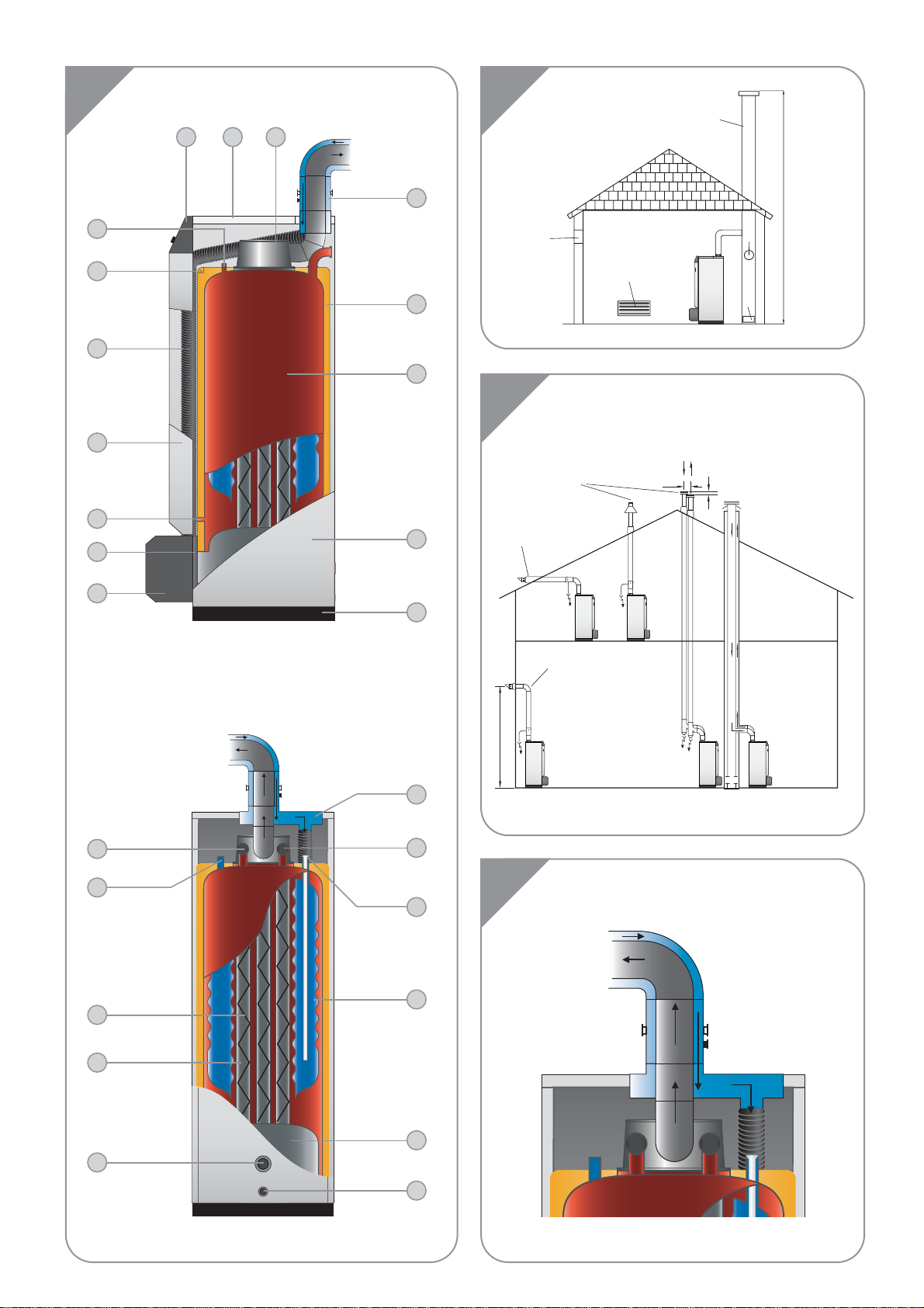
BOILER CAPTIONS (see illustration K)
1. Control panel
2. Removable jacket top
3. Flue reduction collar
4. Measuring unit
5. CFC-free polyurethane foam insulation
6. Inner ring-shaped domestic hot water tank
7. Side panel
8. Base
9. Burner and burner chamber plate cover
10. Burner chamber plate
11. Control thermostat bulb
12. Removable front panel
13. Tube supplying air to venturi
14. Manual reset safety thermostat - 103 °C
15. Cut-off thermostat bulb - 95 °C
16. Balanced flue connection unit
17. Heating return
18. Domestic cold water inlet
19. Inner ring-shaped domestic hot water tank
20. Combustion chamber
21. Boiler drain
22. Lower heating return
23. Flue pipes
24. Turbulators
25. Domestic hot water outlet
26. Central heating flow pipe
DESCRIPTION
Page 10
4
EN
GENERALE
The units are delivered fully assembled, tested and packed on a timber base with shockproof edges and protected by heat-shrunk plastic
film. On reception and after unpacking, check the equipment for damage.
For transport purposes, refer to the weights and dimensions given below.
MAXIMUM OPERATING CONDITIONS
Maximum service pressure (tank full of water)
- Primary circuit: 3 bar
- Secondary circuit: 10 bar
Test pressure
(tank full of water)
- Primary circuit: 4.5 bar
- Secondary circuit: 13 bar
Operating temperature
- Maximum temperature: 90 °C
Water quality
• Chlorides: < 150 mg/l (Stainless steel 304)
< 2000 mg/l (Duplex)
• 6 ≤ ph ≤ 8
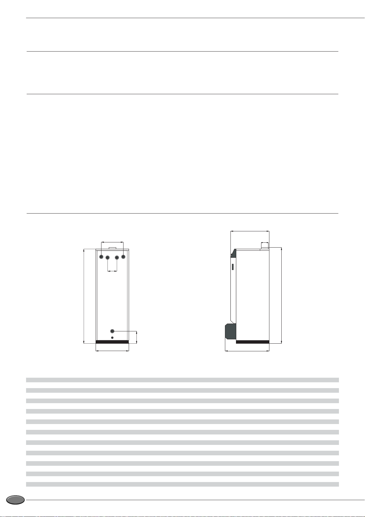
DIMENSIONS
TECHNICAL SPECIFICATION
FV/35 FV/50
A mm 1585 1830
B mm 390 390
C mm 200 200
D mm 542 542
E mm 125 125
F mm 645 645
G mm 80/80/125 100/100/150
H mm 1610 1880
I mm 800 800
Weight empty Kg 182 220
F
G
I
H
B
C
D
A
E
Page 11

5
EN
TECHNICAL SPECIFICATION
GENERAL FEATURES
DOMESTIC HOT WATER PERFORMANCE
FV/35 FV/50
Operating at 80 °C
Peak delivery at 40 °C (≤ T = 30 °C) L/10’ 283 377
Peak delivery at 40 °C (≤ T = 30 °C) L/60’ 1024 1485
Continuous delivery at 40 °C (≤ T = 30 °C) L/h 920 1352
Tank refill time at 60 °C
Initial heating time minutes 20 13
After drawing off 140 L at 45° C minutes 10 8
FV/35 FV/50
Input L/10’ 34.9 50
Output L/60’ 32.62 46.75
Maintenance loss at 60 °C as % of rated value % 0.8/0.7 0.6/0.45
Total capacity L 127 162
Primary capacity L 62 82
Heating connection Ø 1” 1”
Domestic hot water connection Ø 3/4” 3/4”
Hot water tank heat exchange surface m
2
1.99 2.46
Combustion efficiency % 94.7 93.5
Average CO2 % 13 13
Mass rate of combustion products g/sec. 14.8 21.2
Page 12
6
EN
BOILER ROOM
Important
•Keep vents free at all times.
• Do not store inflammable products in the boiler room.
•Take care not to store corrosive products near the boiler, such as
paints, solvents, chlorine, salt, soap and other cleaning products.
Access
The boiler room must be large enough to allow good access
to the boiler.The following minimum distances (mm) are required
around the boiler:
- front 500
- behind 150
- sides 100
- above 700
Ventilation
The boiler room must be fitted with top and bottom vents as shown
in illustration "L".
The table below is an example compliant with the Belgian
standard.
Note:
(B) and (C) only for B23 type connections
For other countries, refer to their regulations.
Base
The base on which the boiler rests must be made of noncombustible
materials.
CHIMNEY CONNECTIONS
IMPORTANT
Boilers must be installed by a qualified heating
engineer, in accordance with the prevailing local
standards and regulations.
The chimney diameter must not be less than the
diameter of the boiler connection.
Chimney connection type: B23 (See illustration L)
The boiler is connected to the chimney by a metal pipe
rising at an angle from the boiler to the chimney.
A chimney connection is required
A. Top vent
B. Bottom vent
C. Draught regulator
D. Inspection cover
E. Chimney height
F. Chimney diameter
Note:
Since the regulations vary from one country to
another, the table above is given for information only.
Due to the high efficiency of our boilers,the flue gases
are released at high temperature.
Therefore there is a risk of condensation in these flue
gases, which could damage some chimneys.
To avoid this risk, it is strongly recommended to line
the chimney.
Contact your installer for more information.
Chimney connection type: C…
(see illustrations M and N)
• C 13 : concentric horizontal connection
• C 33 : concentric vertical connection
• C 43 : Concentric chimney connection
Maximum length for concentric type : 6 metres
Note:
A pipe bend of 90° = an equivalent length of one metre
There should be a drain outlet close to the boiler to
prevent chimney condensates entering the boiler.
To prevent condensation water running out of the
terminal, all horizontal pipes should slope down to the
boiler.
INSTALLATION
FV/35 FV/50
Ventilation
Min. fresh air requirement m3/h 63 90
Top vent (A) dm
2
1.5 1.5
Bottom vent (B) dm
2
1.5 2
Draught regulator (C) Ø 80 100
FV/35 FV/50
Chimney
E = 5 m Ø min. F mm 213 236
E = 10 m Ø min. F mm 179 199
E = 15 m Ø min. F mm 162 179
Page 13
7
EN
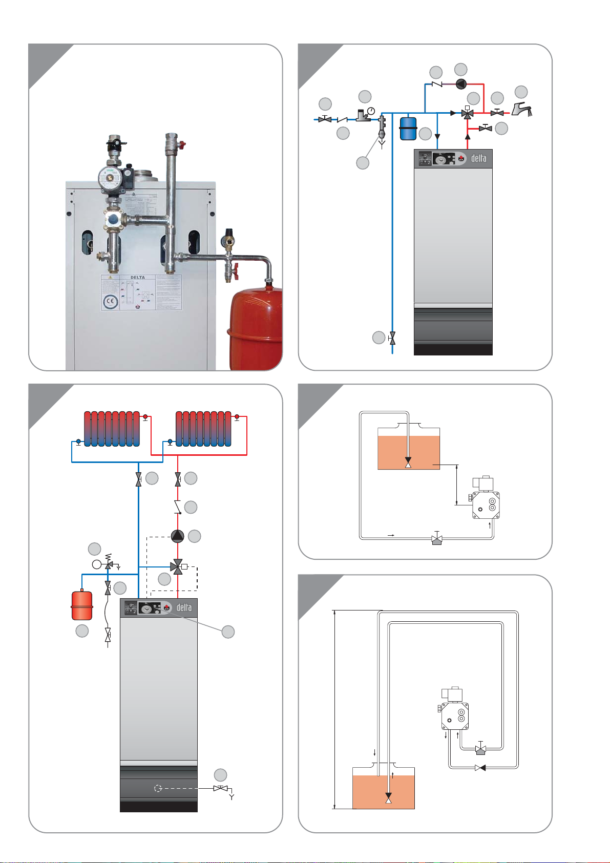
HEATING CONNECTION
Example of a basic circuit configuration
(see illustration G)
1. 3-way motorised mixing valve
2. Safety valve set to 3 bar with pressure gauge
3. Circulator
4. Non-return valve
5. System filling valve
6. Expansion tank
7. ACV 13 controller
(see controller kit page 7)
8. Central heating isolating valve
9. Drain cock
Hydraulic kit + ACV heating kit (see illustration F)
ACV offers an optional pre-assembled circulation kit comprising:
- a circulator.
- a 3-way manual motorisable valve.
- connecting pipes including a second optional circuit.
- two isolating valves.
- adapters for mounting safety valve with pressure gauge and filling
valve to right or left of expansion tank.The expansion tank is not
included.
HOT WATER CONNECTION
Pressure reducer
If the water mains pressure is greater than 6 bar, a pressure
reducer calibrated to 4.5 bar must be fitted.
Safety unit
The tank safety unit must be ACV approved and calibrated to 7 bar.
The valve discharge must be connected to the sewer drain.
Hot water expansion tank
Installing a hot water expansion tank avoids any risk of pressure
surges due to water-hammer or pressure variations.
Hot water circulation
If the tank is situated a long way from the point of use, then
installing a closed return circuit can provide a faster supply of hot
water always available.
Example of connection with thermostatic valve
(see illustration H)
1. Safety unit
2. Pressure reducer
3. Thermostatic mixing valve
4. Hot water circulator
5. Non-return valve
6. Hot water type expansion tank
7. Cold water feed valve
8. Drawoff tap
9. Drain cock
10. Bleed valve
11. Isolating valve
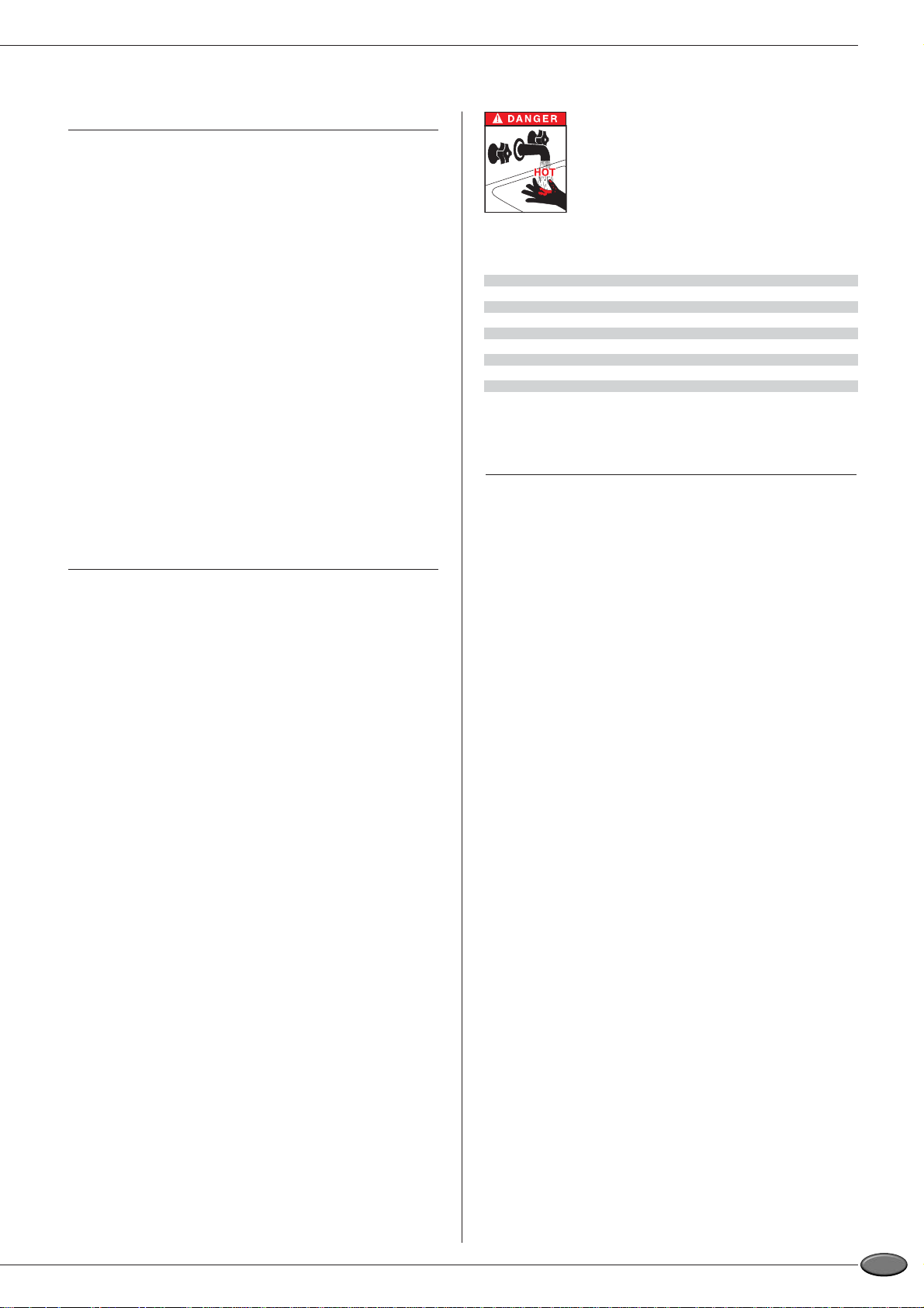
IMPORTANT
As a safety measure against burns,we strongly
recommend installing a thermostatic mixer.
Optional fittings available
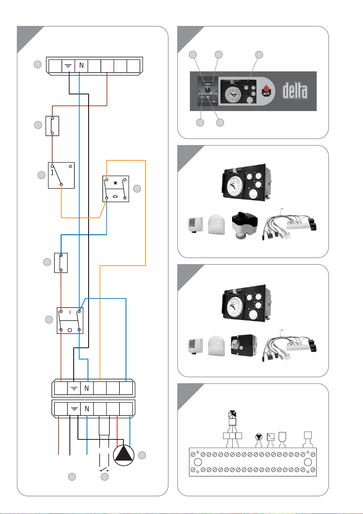
CONTROLLER KITS
KIT 1: ACV 13.00 / Basic (see illustration C)
Basic kit for regulating flow temperature according to weather
conditions.
It comprises: temperature regulator with analogue timer, water
temperature detector (-30°/130°C), outside temperature detector
(-30°/50°C), 230V - 3 spindle servomotor SSY 319 and intermediate
socket.
KIT 2: ACV 13.00 / Standard (see illustration D)
Standard kit for regulating flow temperature according to weather
conditions.
It comprises: temperature regulator with analogue timer, water
temperature detector (-30°/130°C), outside temperature detector
(-30°/50°C), 230V - 3 spindle servomotor SQK 349 and intermediate
socket.
Wiring diagram of ACV controller kits
(see illustration E)
B2. Temperature probe
B9. Outside temperature probe
B5. Analogue/digital room thermostat
P1. Central heating pump
Y1/Y2/N. Mixer valve (SSY 319 or SQK 349)
bl. Blue N
n/z. Black Y2
br. Bro wn Y1
INSTALLATION
Safety unit Ø 3/4”
Pressure reducer Ø 3/4“
Thermostatic mixing valve Ø 3/4”
Expansion tank 5 litres
Page 14
8
EN
Height H Ø 6 mm Ø 6 mm Ø 8 mm
4.0 m 100 m 100 m 100 m
3.5 m 100 m 100 m 100 m
3.0 m 100 m 197 m 100 m
2.5 m 100 m 181 m 100 m
2.0 m 100 m 165 m 100 m
1.5 m 197 m 149 m 177 m
1.0 m 165 m 132 m 151 m
0.5 m 132 m 116 m 126 m
Nozzle uo to 2.5 Kg uo to 5.0 Kg uo to 10.0 Kg
Height H Ø 6 mm Ø 8 mm Ø 10 mm
0.0 m 17 m 53 m 100 m
0.5 m 15 m 47 m 100 m
1.0 m 13 m 41 m 199 m
1.5 m 11 m 34 m 184 m
2.0 m 19 m 28 m 168 m
2.5 m 17 m 22 m 153 m
3.0 m 15 m 15 m 137 m
3.5 m 13 m 19 m 122 m
ELECTRICAL CONNECTION
Power supply
The boiler operates with a 230 V - 50 Hz single phase supply.
An on-off mains switch box with 6 A fuses must be fitted outside the
boiler to allow power to be shut off during servicing and before any
repairs are carried out on the boiler.
Conformity
Boiler installation must comply with the prevailing local technical
standards and legislation.
Safety
The stainless steel tank must be earthed separately.
The power to the boiler must be switched off before
any work is carried out.
Boiler electrical wiring (see illustration A)
1. Control thermostat (60/90 °C)
2. On/off switch
3. Summer/winter selector
4. Safety thermostat (103 °C max.)
5. Boiler power connection
6. Heating circulator connection
7. Burner connection
8. Room thermostat
9. Cut-off thermostat (95 °C)
10. Boiler power plug
B. Blue
Br. Brown
Gr. Green
Or. Orange
R. Red
Y/Gr. Yellow / Green
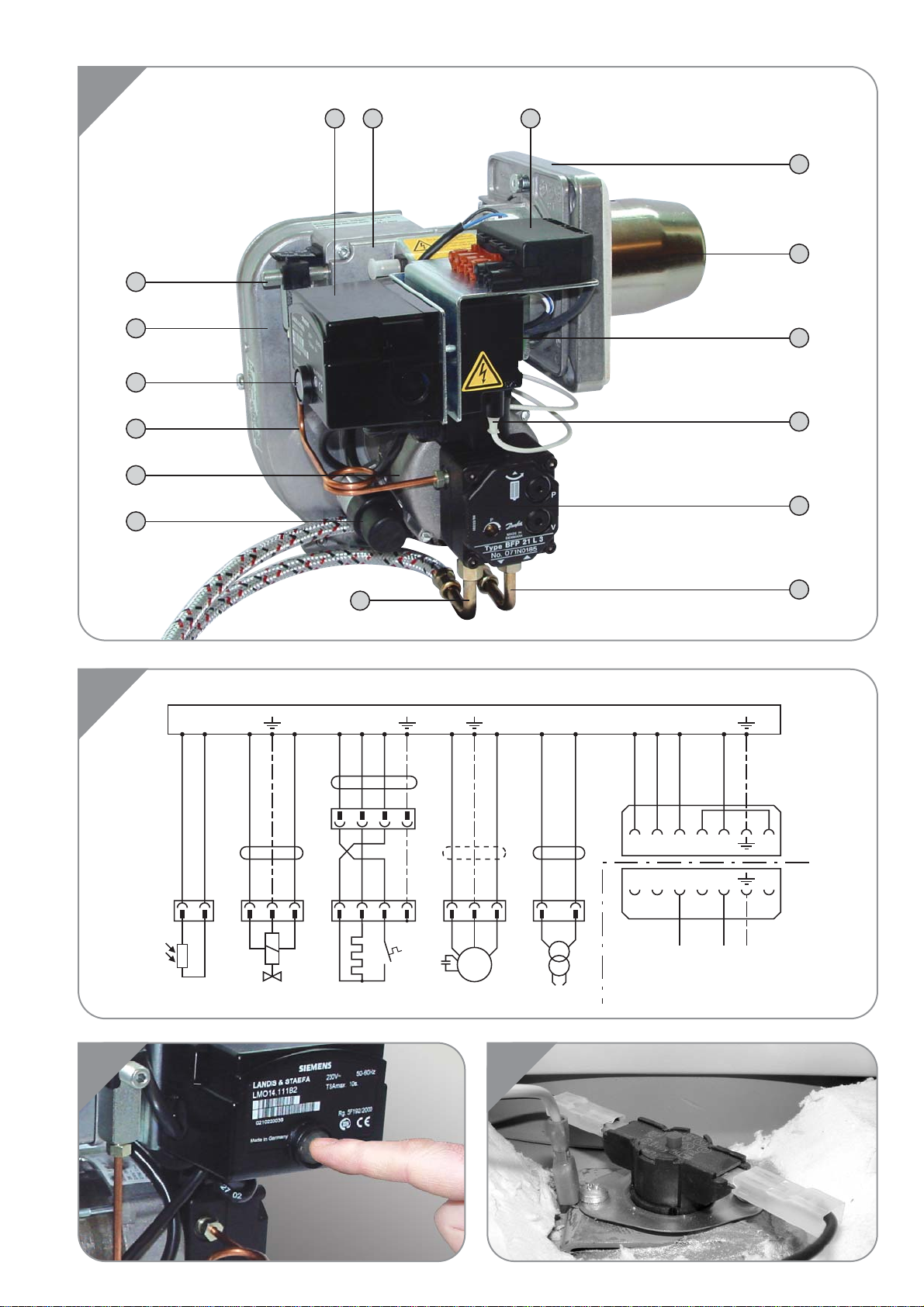
BMV1 and BMV2 oil burner electric wiring
(see illustration P)
The burner is supplied with power by a 3-core cable, to be plugged
into the connector situated on the burner.Instructions for connection
are given in the burner technical manual.
A1. Automatic igniting device
M. Burner motor
QRB. Photoelectric resistor
OH. Heater
Z. Transformer
BV1. Magnetic valve
X1. Burner Euro plug connector
X2. Boiler plug connector
B. Blue
Br. Brown
Bk. Black
W. White
Y/Gr. Yellow / Green
OIL SUPPLY
System construction and installation must be in accordance with
DIN 4755. Local regulations must be followed.
Oil pipes must be brought sufficiently close to the burner so that the
tubes can be connected without strain. On the aspiration side of the
line, fit a filter with a quick closing valve. Install a check valve on the
return line.
The Burner can operate with a 1 or 2 line system.
In series, the burner is designed to operate with a two-line system.
The vacuum in the aspiration line should not exceed 0.4 bar.
Refer to the ACV BMV1 and BMV2 burner manual
supplied with them.
Dual-line installation (see illustration J)
INSTALLATION
Single-line installation (see illustration I)
Page 15

9
EN
BURNER FEATURES
ACV BMV1 AND BMV2 OIL BURNERS
Description
For the Delta Performance oil-fuelled balanced flue model, we have
opted for the all-new technology of the ACV BMV1 and BMV2 oil
burner, manufactured from high quality components combining
performance with perfect combustion.
CO2 chart for the ACV BMV1 and BMV2 burner
ACV BMV1 AND BMV2
BURNER FACTORY SETTINGS
FV/35 FV/50
Burner BMV1 BMV2
Input kW 34.9 50
Nozzle gal/h 0,75 1.25
Nozzle angle 60°H 60°H
Oil flow Kg/h 2.95 4.22
Pump pressure bar 11.8 9.5
Flue gas index 0 - 0.5 0 - 0.5
Air reducer % 37 60
Air inlet % 90 90
Nozzle line pressure mbar 3.5 - 4 3.5 - 4
Nozzle line mm 10 10
Weight Kg 14.5 14.5
Outside temperature
ACV BMV1 AND BMV2 BURNER CAPTIONS
(see illustration O)
1. Control unit
2. Nozzle line protection
3. Warning lamp
4. Electric plug connector
5. Attachment bracket
6. Burner blast tube
7. Ignition unit
8. High tension ignition cable
9. Oil pump
10. Oil aspiration line connection
(circuit with return only)
11. Oil return connection
12. Motor condenser
13. Motor
14. Pump / nozzle connecting pipe
15. Burner casing
16. Nozzle line adjustment screw
WARNING: Set the % of CO
2 as per the data in the diagram above
14 %
13,5 %
13 %
% CO2
12,5 %
12 %
-10 0 10 203040
Page 16

10
EN
FILLING THE DOMESTIC HOT WATER AND
HEATING CIRCUITS (see illustrations B, G et H)
IMPORTANT
The hot water tank must be pressurised before the
heating circuit is filled.
1. Fill the domestic hot water circuit and bring it up to pressure.
2. Fill the heating circuit taking care not to exceed the 2 bar
pressure limit.
3. Vent the air from the top of the boiler.
4. After venting the air from the system, bring the pressure up to
the static head plus 0.5 bar: 1.5 bar = 10m -2 bar = 15 m.
5. Check the power connection, the boiler room ventilation, and
ensure that there are no leaks in the flue gas discharge pipes.
6. Set the boiler thermostat to between 60 and 90 °C.
7. Set the Summer/Winter selector to the desired position.
8. Switch the on/off switch to the ON position.
9. Check the oil supply
(and return).
10. Carry out the required venting, measurement and setting
procedures.
STARTING ACV BMV1 AND BMV2 BURNERS
Refer to the ACV BMV1 and BMV2 burner manual supplied with them.
RECOMMENDATION
ACV advises that boilers should be serviced at least once a year.
The burner must be serviced and tested by a competent engineer.
SERVICING THE BOILER (see illustration K)
1. Switch off the power at the mains switch outside the boiler and
shut off the oil supply.
2. Set the on/off switch on the control panel to the OFF position.
3. Remove the top cover of the boiler (2) and take off the top of the
chimney reduction (3).
5. Remove the turbulators (23) from the flue pipes (22) for cleaning.
Change them if in poor condition.
6. Unscrew the burner chamber plate (10).
7. Brush the flue pipes (22).
8. Clean the burner chamber (18) and the burner.
9. Check the condition of the burner chamber plate insulation.
SERVICING THE SAFETY DEVICES
- Check that all thermostats and safety devices are working
properly : boiler thermostat, cut-off thermostat and manually reset
safety thermostat.
-Test the safety valv es on the central heating and hot w ater circuits .
SERVICING THE BURNER
Refer to the ACV BMV1 and BMV2 burner manual supplied with them.
EMPTYING THE BOILER
Water flowing out of the drain cock is extremely
hot and can cause severe burns.
Keep people away fr om discharges of hot water.
Emptying the heating circuit (see illustration G)
1. Set the on/off switch on the control panel to the OFF position,
turn off the power at the external mains switch and close the oil
feed valve.
2. Close the isolating valves (8).
3. Connect a hose to the drain cock (9).
4. Open the drain cock to empty the primary circuit.
Emptying the hot water circuit (see illustration H)
1. Set the on/off switch on the control panel to the OFF position,
turn off the power at the external mains switch and close the oil
feed valve.
2. Lower the pressure in the heating circuit until the pressure
gauge indicates zero bar.
3. Close the valves (7 and 11).
4. Open valves (9) and (10) (first 9 then 10).
5. Let the water empty into the drain .
For the tank to be emptied, valve (9) must be situated
at ground level.
SERVICINGSTARTUP
Page 17
11
EN
USING THE BOILER
Have your system serviced every year by a qualified
heating engineer. If the boiler is subject to heavy
usage, it may need more frequent servicing. If this is
the case, ask your installer for advice.
Starting the burner:
In normal operation, the burner starts automatically
whenever the boiler temperature falls below the set
temperature.
Before doing any work on the boiler, switch off the
power at the mains switch installed in the boiler room
by the electrician.
On the control panel, switch off the ON/OFF switch.
Getting to know the control panel (see illustration B)
The user should not access the components inside
the control panel.
1. Control thermostat - 60 to 90 °C
When the boiler is used only to produce domestic hot water, the
temperature can be set between 60 and 90 °C. If the boiler is used
for both hot water and heating, the control thermostat will, as a
general rule, be set to 80 °C to ensure optimum operating conditions.
2. ON/OFF switch
Used to start and stop the boiler.
3. Summer/winter selector
Starts and stops the heating pump
(if fitted).
4. Thermometer
Shows the boiler temperature in the primary circuit.
The temperature should not exceed 90 °C.If it does, switch off the
boiler and check the thermostat settings. If there is a fault, call a
heating engineer.
5. Controller
See the user instructions supplied with the unit if you have chosen
this option.
6. Burner reset
7. Burner indicator lamp
Safety valve (heating)
If water flows from one of the safety valves, shut off the boiler and
call your heating engineer.
A monthly inspection is recommended:
Lift the lever on the emptying de vice for a f e w seconds to ensure that
the safety valve is working properly.
If a fault occurs after this short trial, call the installing
engineer.
Safety unit (domestic hot water)
A monthly inspection is recommended.
Lift the lever on the emptying de vice for a f e w seconds to ensure that
the safety unit is working properly.
If a fault occurs after this short trial, call the installing
engineer.
Water flowing out of the safety valve or safety
unit may be extremely hot and can cause very
serious burns.
USER GUIDE
Page 18

12
EN
RESETTING ACV BMV1 AND BMV2 BURNERS
(see illustration Q)
If the burner is not working:
1. Remove the protective cover of the burner.
2. If the red light is lit, press the button to start the burner.
3. If the burner lights, replace the cover.
If the burner does not operate, switch off the power
before removing the front cover panel.
4. Reset the safety thermostat on top of the boiler. (see illustration R).
Wait until the boiler temperature is below 60 °C then
replace the front cover panel.
5. If the burner lights, replace its cover.
6. If the fault persists, notify the installing engineer.
Starting the burner
In normal operation, the burner starts automatically whenever the
boiler temperature falls below the set temperature.
To ensure your system operates properly, have it
professionally serviced once a year before the central
heating season begins.
USER GUIDE
Page 19

13
FR
NOTICE D’INSTALLATION,
D’UTILISATION ET D’ENTRETIEN
FV 35
avec brûleur
fioul ACV BMV(K)1
FV 50
avec brûleur
fioul ACV BMV(K)2
performance
ventouse
Page 20
14
FR
INTRODUCTION 14
Destinataires de cette notice 14
Symboles 14
Normes en usage 14
Avertissements 14
DESCRIPTION 15
Description générale 15
Principe de fonctionnement 15
Caractéristiques constructives 15
Légende de la chaudière 15
CARACTERISTIQUES TECHNIQUES 15
Généralités 16
Conditions extrêmes d’utilisation 16
Dimensions 16
Performances en eau chaude sanitaire 17
Caractéristiques générales 17
INSTALLATION 18
Chaufferie 18
Raccordements cheminée 18
Raccordements chauffage 19
Raccordements sanitaire 19
Kit de régulation 19
Raccordement électrique 20
Alimentation fioul 20
CARACTERISTIQUES BRULEUR 21
Brûleurs fioul ACV BMV1 et BMV2 21
Réglages usine des brûleurs ACV BMV1 et BMV2 21
Légende des brûleurs ACV BMV1 et BMV2 21
MISE EN SERVICE 22
Remplissage des circuits sanitaire et chauffage 22
Mise en service des brûleurs ACV BMV1 et BMV2 22
ENTRETIEN 22
Recommendation 22
Entretien de la chaudière 22
Entretien des dispositifs de sécurité 22
Entretien du brûleur 22
Vidange de la chaudière 22
GUIDE DE L’UTILISATEUR 23
Utilisation de la chaudière 23
Mise en sécurité des brûleurs ACV BMV1 et BMV2 24
DESTINATAIRES DE CETTE NOTICE
Cette notice s’adresse:
- à l’ingénieur chargé de la prescription
- à l’installateur
- à l’utilisateur
- aux techniciens en charge de l’entretien
SYMBOLES
Les symboles suivants sont utilisés dans cette notice:
Instruction essentielle pour un fonctionnement
correct de l’installation.
Instruction essentielle pour la sécurité des
personnes et de l’environnement.
Danger d’électrocution.
Danger de brûlure.
NORMES EN USAGE
Les produits ont reçu le certificat “CE” selon les normes en vigueur
dans différents pays (Directive Européenne 92/42/CEE “rendement”).
Ces produits ont également reçu le label belge “OPTIMAZ”.
AVERTISSEMENTS
Cette notice fait partie intégrante de l’équipement auquel elle se
rapporte et doit être remise à l’utilisateur.
L’installation et l’entretien du produit seront exécutés par des
techniciens qualifiés, en conformité avec les normes en vigueur.
ACV décline toute responsabilité pour tous dégats consécutifs à une
erreur d’installation et en cas d’utilisation d’appareils ou accessoires
qui ne sont pas spécifiés par ACV.
Le manque d’observation des instructions relatives
aux opérations et procédures de contrôle peut
entraîner des blessures aux personnes ou des risques
de pollution.
Note:
ACV se réserve le droit de modifier les caractéristiques techniques
et les équipements de ses produits sans notification préalable.
INDEX INTRODUCTION
Page 21

15
FR
DESCRIPTION GENERALE
• Chaudière à double service (chauffage et eau chaude sanitaire).
•Production d’eau chaude sanitaire de type accumulation indirecte
TANK-IN-TANK.
• Equipement nécessaire: un kit de raccordement hydraulique pour
l’alimentation du circuit de chauffage (disponible en option).
• Le tableau de commande comporte un interrupteur général, un
thermostat de réglage, un thermomètre, un commutateur
Eté/Hiver et une prédécoupe pour le système de régulation
intégré - ACV
(en option).
• Le modèle Delta Performance FV, peut être raccordé en ventouse
avec une connections cheminée concentrique de type C…, ou
avec une connections cheminée de type B23 directement à la
cheminée.
• Le modèle Delta Performance FV 35 avec une puissance utile fixe
de 35 est équipé du brûleur fioul ACV BMV1.
• Le modèle Delta Performance FV 50 avec une puissance utile fixe
de 50 est équipé du brûleur fioul ACV BMV2.
PRINCIPE DE FONCTIONNEMENT
Le concept “Tank-inTank”
La série Delta Performance ventouse se distingue des producteurs
d’eau chaude traditionnels par son ballon annulaire immergé dans le
fluide primaire contenu dans le corps externe. Lorsqu’il y a une
demande de chaleur du système de chauffage ou du circuit d’eau
chaude sanitaire, le potentiomètre enclenche le brûleur. Les gaz de
combustion réchauffent rapidement le fluide primaire, tout en créant
une circulation naturelle autour du ballon.
Chauffage indirect de l’eau sanitaire
Cette circulation favorise l’échange de chaleur entre le fluide primaire
et l’eau sanitaire, qui s’opère à travers toute la surface du ballon. Les
ondulations sur les viroles intérieure et extérieure du ballon annulaire
augmentent encore la surface d’échange de chaleur et accélèrent le
réchauffement de l’eau sanitaire.
Réglage aisé et sécurité assurée
Une seule commande permet de régler la température de l’eau, tant
du circuit primaire que du circuit sanitaire, grâce au thermostat de
réglage situé sous le ballon dans le circuit primaire.
Un thermostat limite, placé en partie supérieure de la chaudière,
coupe automatiquement le brûleur lorsque la température de l’eau
du circuit primaire atteint 95 °C. Un thermostat de sécurité à
réarmement manuel verrouille le brûleur si la température atteint
103 °C.
CARACTERISTIQUES CONSTRUCTIVES
Corps externe
Le corps externe contenant le fluide primaire est réalisé en acier
STW 22 de forte épaisseur.
Echangeur accumulateur de type “Tank-inTank”
Le ballon interne de type annulaire à grande surface de chauffe pour
la production d’eau chaude sanitaire est construit en acier inoxydable
Chrome/Nickel 18/10.Il est ondulé sur toute sa hauteur par un procédé
de fabrication exclusif et est entièrement soudé à l’argon suivant le
procédé TIG (Tungsten Iner t Gas).
Circuit des gaz de combustion
Le circuit des gaz de combustion est protégé par une peinture
résistante à haute température. Celui-ci comprend:
•Tubes de fumée Les différents modèles Delta Performance
ventouse comportent, 8 tubes de fumée en acier d’un diamètre
intérieur de 64 mm. Chacun des tubes est équipé d’un turbulateur
en acier spécial destiné à améliorer l’échange thermique et à
réduire la température des fumées.
• La chambre de combustion étanche est refroidie par eau.
Isolation
Le corps de la chaudière est entièrement isolé par de la mousse de
polyuréthane rigide à haut coefficient d’isolation thermique, projetée
sans CFC.
Jaquette
La chaudière est revêtue d’une jaquette en acier ayant subi un
dégraissage et une phosphatation avant la peinture cuite au four à
220 °C.
LEGENDE DE LA CHAUDIERE (voir illustration K)
1. Tableau de commande
2. Couvercle de la jaquette démontable
(Accès aux turbulateurs)
3. Réduction cheminée
4. Elément de mesure avec récupérateur des condensats
5. Isolation en mousse de polyuréthane sans CFC
6. Ballon interne annulaire contenant l’eau chaude sanitaire
7. Jaquette latéral
8. Socle
9. Coiffe du brûleur
10. Porte foyère
11. Bulbe du thermostat de réglage
12. Face avant démontable
13. Flexible d’amnée d’air au venturi
14. Thermostat de sécurité 103 °C à réarmement manuel
15. Bulbe du thermostat limite 95 °C
16. Adaptateur ventouse
17. Retour chauffage
18. Arrivée eau froide sanitaire
19. Ballon interne annulaire contenant l’eau chaude sanitaire
20. Chambre de combustion
21. Vidange de la chaudière
22. Retour chauffage
23. Tubes de fumée
24. Turbulateurs
25. Sortie eau chaude sanitaire
26. Départ chauffage
DESCRIPTION
Page 22

16
GENERALITES
Les appareils livrés arrivent complètement assemblés, testés et emballés sur un support en bois avec des bords anti-choc et protégés par un film
en plastique thermorétractable.Au moment de la réception et après avoir retiré l’emballage, contrôler que les appareils ne sont pas endommagés.
Pour le transport, vous référer aux dimensions et poids ci-dessous:
CONDITIONS EXTREMES D’UTILISATION
Pression de service maximum (ballon rempli d’eau)
- Circuit primaire: 3 bar
- Circuit secondaire: 10 bar
Pression d’épreuve
(ballon rempli d’eau)
- Circuit primaire: 4.5 bar
- Circuit secondaire: 13 bar
Température d’utilisation
- Température maximum: 90 °C
Qualité de l’eau
• Chlorures: < 150 mg/l (inox 304)
< 2000 mg/l (Duplex)
• 6 ≤ ph ≤ 8
DIMENSIONS
CARACTERISTIQUES TECHNIQUES
FR
FV/35 FV/50
A mm 1585 1830
B mm 390 390
C mm 200 200
D mm 542 542
E mm 125 125
F mm 645 645
G mm 80 / 80 / 125 100 / 100 / 125
H mm 1610 1880
I mm 800 800
Poids à vide Kg 182 220
F
G
I
H
B
C
D
A
E
Page 23

17
CARACTERISTIQUES TECHNIQUES
FR
CARACTERISTIQUES GENERALES
PERFORMANCE EAU CHAUDE SANITAIRE
FV/35 FV/50
Régime de fonctionnement à 80 °C
Débit de pointe à 40 °C (≤ T = 30 °C) L/10’ 291 377
Débit de pointe à 40 °C (≤ T = 30 °C) L/60’ 1044 1485
Débit continu à 40 °C (≤ T = 30 °C) L/h 920 1352
Durée de recharge du ballon à 60 °C
Mise en régime minutes 20 13
Après puisage de 140 L à 45 °C minutes 10 8
FV/35 FV/50
Débit calorifique (input) L/10’ 34.9 50
Puissance nominale utile (output) L/60’ 32.62 46.75
Perte d’entretien à 60 °C de la valeur nominale % 0.8 / 0.7 0.6 / 0.45
Capacité totale L 127 162
Capacité du circuit primaire L 62 82
Raccordement chauffage Ø 1” 1”
Raccordement eau chaude sanitaire Ø 3/4” 3/4”
Surface d’échange du ballon sanitaire m
2
1.99 2.46
Rendement de combustion % 94.7 93.5
CO2 moyenne % 13 13
Débit massique des produits de combustion g/sec. 14.8 21.2
Page 24

18
CHAUFFERIE
Important
• Ne jamais obstruer les ventilations.
• Ne pas entreposer des produits inflammables dans la chaufferie.
•Veiller à ne pas entreposer des produits corrosifs à proximité de la
chaudière, tels que peinture, solvants, chlore , sel, sa von et autres
produits de nettoyage.
Accessibilité
Le local de chauffe sera suffisamment dimensionné pour permettre
une bonne accessibilité à la chaudière. Il convient de respecter les
distances minimales suivantes autour de la chaudière (mm):
- à l’avant 500
- à l’arrière 150
- latéral 100
- au-dessus 700
Ventilation
La chaufferie doit être équipée d’une ventilation basse et d’une
ventilation haute selon l’illustration “L”
Le tableau ci-dessous est un exemple conforme au standard
Belge.
Note:
(B) et (C) uniquement pour les raccordements de type B23
Les autres pays peuvent se référer à leur réglementation.
Socle
Le socle sur lequel sera posée la chaudière doit être construit dans
des matériaux incombustibles.
RACCORDEMENTS CHEMINEE
IMPORTANT
L’installation sera réalisée par un installateur agréé,
en conformité avec les normes et codes locaux en
vigueur.
Le diamètre de la cheminée ne doit pas être inférieur
à celle de la chaudière
Raccordement cheminée de type: B23 (voir illustration L)
Le raccordement à la cheminée se fera au moyen d’un conduit
métallique placé en pente ascendente de la chaudière vers la
cheminée.
Un raccord de cheminée est nécessaire.
A. Ventilation haute
B. Ventilation basse
C. Régulateur de tirage
D. Regard de visite
E. Hauteur de la cheminée tubée
F. Diamètre de la cheminée
Remarque:
Etant donné que les réglementations varient d’un
pays à l’autre, le tableau ci-dessus est donné à titre
indicatif uniquement.
Le rendement élevé de nos chaudières implique que
les fumées sortent à basse température.
Par conséquent, un risque de condensation de ces
fumées existe, qui peut entraîner des dégâts dans
certaines cheminées. Afin d’éviter ce risque, il est
vivement conseillé de faire tuber le conduit de
cheminée.
Veuillez contacter votre installateur pour de plus
amples renseignements à ce sujet.
Raccordement cheminée de type: C…
(voir illustrations M et N)
• C 13 : raccordement horizontal concentrique
• C 33 : raccordement vertical concentrique
• C 43 : raccordement à la cheminée concentrique
Longeur maximal concentrique : 6 metres
Note:
Un coude de 90° = à une longeur équivalent d’un metre
Une sortie à l’égout doit être à proximité de la
chaudière afin d’éviter que les condensats de la
cheminée n’entre dans la chaudière.
Pour éviter que l’eau de condensation ne s’écoule du
terminal, tous les passages de conduits horizontaux
doivents descendre vers la chaudière.
INSTALLATION
FR
FV/35 FV/50
Ventilation
Apport d’air frais min. m3/h 63 90
Ventilation haute (A) dm
2
1.5 1.5
Ventilation basse (B) dm
2
1.5 2
Régulateur de tirage (C) Ø 80 100
FV/35 FV/50
Cheminée
E = 5 m Ø min. F mm 213 236
E = 10 m Ø min. F mm 179 199
E = 15 m Ø min. F mm 162 179
Page 25

19
RACCORDEMENT CHAUFFAGE
Exemple de raccordement simple circuit
(voir illustration G)
1. Vanne mélangeuse à 3 voies motorisée
2. Soupape de sécurité tarée à 3 bar avec manomètre
3. Circulateur
4. Clapet anti-retour
5. Vanne de remplissage de l’installation
6. Vase d’expansion
7. Régulation ACV 13
(voir kit de régulation page 19)
8. Vanne d’isolement chauffage
9. Vidange
Kit hydraulique + Kit chauffage sol ACV (voir illustration F)
ACV offre en option un kit hydraulique pré-assemblé comprenant:
- Un circulateur.
- Une vanne 3 voies manuelle motorisable.
- Les tuyauteries de raccordement incluant un deuxième circuit
possible.
- Deux vannes d’isolement.
- Les raccords pour montage à droite ou à gauche du vase
d’expansion, de la soupape de sécurité avec manomètre et de la
vanne de remplissage.Le vase d’expansion n’est pas inclus.
RACCORDEMENT SANITAIRE
Réducteur de pression
Si la pression de l’eau de distribution est supérieure à 6 bar, il faut
prévoir un réducteur de pression taré à 4,5 bar.
Groupe de sécurité
Le groupe de sécurité du ballon sera agréé par ACV et taré à 7 bar.
Prévoir le raccordement de la décharge de la soupape à l’égoût.
Vase d’expansion sanitaire
L’installation d’un vase d’expansion sanitaire permet d’éviter tout
risque de surpression due aux coups de bélier, ou aux variations de
pression.
Circulation d’eau chaude
En cas de grande distance entre le ballon et le point d’utilisation,
l’installation d’un circuit fermé de recirculation peut assurer en
permanence un puisage d’eau chaude plus rapide.
Exemple de raccordement avec vanne thermostatique
(voir illustration H)
1. Groupe de sécurité
2. Réducteur de pression
3. Mitigeur thermostatique
4. Circulateur sanitaire
5. Clapet anti-retour
6. Vase d’expansion de type sanitaire
7. Robinet d’alimentation d’eau froide
8. Robinet de puisage
9. Robinet de vidange
10. Robinet de purge
11. Vanne d’isolment
IMPORTANT
Par mesure de sécurité pour éviter les brûlures,
l’installation d’un mitigeur thermostatique est
vivement conseillée
Accessoires disponibles en option
KITS DE REGULATION
KIT 1: ACV 13.00 / Basic (voir illustration C)
Kit de base pour la régulation de la température de départ en
fonction des conditions atmosphériques.
Il comprend: régulateur de température avec horloge analogique,
sonde d’applique de température de l’eau (-30/130°C), sonde
extérieure (-30/50°C), servomoteur SSY 319 - 230 V - 3 broches et
un socle intermédiaire.
KIT 2: ACV 13.00 / Standard (voir illustration D)
Kit standard pour la régulation de la température de départ en fonction
des conditions atmosphériques.
Il comprend: régulateur de température avec horloge analogique,
sonde d’applique de température de l’eau (-30/130°C), sonde
extérieure (-30/50°C), servomoteur SQK 349 - 230 V - 3 broches et
un socle intermédiaire.
Schéma électrique des kits de régulation ACV
(voir illustration E)
B2. Sonde de température
B9. Sonde extérieure
B5. Sonde d’ambiance analogique/digital
P1. Pompe chauffage
Y1/Y2/N. Vanne mélangeuse (SSY 319 ou SQK 349)
bl. Bleu N
n/z. Noir Y2
br. Brun Y1
INSTALLATION
FR
Groupe de sécurité Ø 3/4”
Réducteur de pression Ø 3/4“
Mitigeur thermostatique Ø 3/4”
Vase d’expansion 5 litres
Page 26

Hauteur H Ø 6 mm Ø 6 mm Ø 8 mm
4.0 m 100 m 100 m 100 m
3.5 m 100 m 100 m 100 m
3.0 m 100 m 197 m 100 m
2.5 m 100 m 181 m 100 m
2.0 m 100 m 165 m 100 m
1.5 m 197 m 149 m 177 m
1.0 m 165 m 132 m 151 m
0.5 m 132 m 116 m 126 m
Gicleur jusqu’à 2.5 Kg jusqu’à 5.0 Kg jusqu’à 10.0 Kg
Hauteur H Ø 6 mm Ø 8 mm Ø 10 mm
0.0 m 17 m 53 m 100 m
0.5 m 15 m 47 m 100 m
1.0 m 13 m 41 m 199 m
1.5 m 11 m 34 m 184 m
2.0 m 19 m 28 m 168 m
2.5 m 17 m 22 m 153 m
3.0 m 15 m 15 m 137 m
3.5 m 13 m 19 m 122 m
20
RACCORDEMENT ELECTRIQUE
Principe d’alimentation
La chaudière fonctionne en monophasé 230 V - 50 Hz.
A l’extérieur de la chaudière, il faut prévoir un coffret a vec interrupteur
général et fusibles de 6 A pour permettre la coupure de l’alimentation
électrique lors des entretiens et avant toute intervention sur la
chaudière.
Conformité
L’installation sera réalisée en conformité avec les normes
techniques et la législation locale en vigueur.
Sécurité
Le ballon en inox doit être raccordé séparément à la terre.
Il est important de couper l’alimentaion électrique de
la chaudière avant toute intervention.
Cablage électrique de la chaudière (voir illustration A)
1. Thermostat de réglage (60/90 °C)
2. Interrupteur général
3. Interrupteur Eté/Hiver
4. Thermostat de sécurité (103 °C max.)
5. Alimentation chaudière
6. Raccordement du circulateur chauffage
7. Raccordement brûleur
8. Thermostat d’ambiance
(en option)
9. Thermostat de limit (95 °C)
10. Raccordement d’alimentation chaudière (prise 6 broches)
B. Bleu
Br. Marron
Gr. Vert
Or. Orange
R. Rouge
Y/Gr. Jaune / Vert
Cablage électrique des brûleurs fioul BMV1 et BMV2
(voir illustration P)
Le brûleur est alimenté électriquement par un câble à 3 conducteurs,
à raccorder au connecteur situé sur le brûleur. Les indications de
raccordement figurent dans la notice technique du brûleur.
A1. Dispositif d’allumage automatique
M. Moteur du brûleur
QRB. Résistance photo-électrique
OH. Réchauffeur
Z. Transformateur
BV1. Soupape magnétique
X1. Prise Euro du brûleur
X2. Prise chaudière
B. Bleu
Br. Marron
Bk. Noir
W. Blanc
Y/Gr. Jaune / Vert
ALIMENTATION FIOUL
La construction est l’installation du système doivent être réalisées
conformément aux normes DIN 4755. Respecter les prescr iptions
locales.
La conduites de fioul doit être amenée suffisamment près du brûleur
pour que les flexibles puissent être raccordés sans contraintes.
Dans la conduite, côté aspiration, monter un filtre à fioul muni d’un
robinet à fermeture rapide.Installer une soupape de retenue dans la
canalisation de retour.
Le Brûleur peut fonctionner avec le système à 1 ou à 2 conduites.
En série, le brûleur est prévu pour fonctionner avec un système à
deux conduites.Le vide dans la conduite d’aspiration ne doit dépasser 0,4 bar.
Pour de plus amples informations spécifiques aux
brûleurs, vous référer à la notice des brûleurs ACV
BMV1 et BMV2 jointe à ceux-ci.
Installation à deux conduites (voir illustration J)
INSTALLATION
FR
Installation à une conduite (voir illustration I)
Page 27

21
CARACTERISTIQUES BRULEUR
FR
BRULEURS FIOUL ACV BMV1 ET BMV2
Description
Pour équiper le modèle Delta Performance fioul ventouse, nous
avons opté pour la toute nouvelle technologie du brûleur fioul ACV
BMV1 et BMV2, fabriqué à partir de composnants de première
qualité, combinant performance et parfaite combustion.
Diagramme de CO2 du brûleur ACV BMV1 et BMV2
REGLAGES USINE DES BRULEURS
ACV BMV1 ET BMV2
FV/35 FV/50
Brûleur BMV1 BMV2
Puissance kW 34.9 50
Gicleur gal/h 0,75 1,25
Angle du gicleur 60°H 60°H
Débit fioul Kg/h 2.95 4.22
Pression pompe bar 11.8 9.5
Indice de fumées 0 - 0.5 0 - 0.5
Réducteur d’air % 37 60
Entrée d’air % 90 90
Pression ligne gicleur mbar 3.5 - 4 3.5 - 4
Ligne gicleur mm 10 10
Poids Kg 14.5 14.5
Température extérieure
LEGENDE DES BRULEURS ACV BMV1 ET BMV2
(voir illustration O)
1. Boîtier de contrôle
(relais)
2. Protection ligne gicleur
3. Lampe témoin
4. Fiche de raccordement électrique 7 broches
5. Bride de fixation sur la porte
6. Tube de flamme
7. Unit d’allumage
8. Cable d’allumage haute tension
9. Pompe fioul
10. Raccordement d’aspiration fioul
11. Raccordement de retour fioul
(uniquement circuit avec retour)
12. Condensateur du moteur
13. Moteur
14. Tube de liaison pompe/gicleur
15. Carter du brûleur
16. Vis de réglage de la ligne gicleur
ATTENTION : Régler le % de CO
2 suivant les données reprisent dans le diagramme ci-dessus.
14 %
13,5 %
13 %
% CO2
12,5 %
12 %
-10 0 10 203040
Page 28

REMPLISSAGE DES CIRCUITS SANITAIRE
ET CHAUFFAGE (voir illustrations B, G et H)
IMPORTANT
Il est essentiel que le ballon sanitaire soit sous
pression avant de remplir le circuit de chauffage.
1. Remplir le circuit sanitaire et le mettre sous pression.
2. Remplir le circuit chauffage en veillant à ne pas dépasser la
pression de 2 bar.
3. Purger l’air contenu en partie supér ieure de la chaudière.
4. Après purge d’air de l’installation, ramener la pression à la
pression statique
(hauteur) augmentée de 0,5 bar: 1,5 bar = 10
- 2 bar = 15 m.
5. Vérifier le raccordement électrique, la ventilation du local de
chauffe et l’étanchéité des conduits d’évacuation des gaz de
combustion.
6. Régler le thermostat chaudière entre 60 et 90 °C.
7. Positionner l’interrupteur Eté/Hiver sur la sélection désirée.
8. Mettre l’interrupteur général sur position ON.
9. Vérifier l’alimentation
(et le retour) fioul.
10. Effectuer les purges, mesures et réglages nécessaires.
MISE EN SERVICE DES BRULEURS
ACV BMV1 ET BMV2
Référez-vous à la notice des brûleurs ACV BMV1 et BMV 2 jointe à
ceux-ci.
RECOMMANDATION
ACV conseille d’assurer l’entretien des chaudières au minimum une
fois l’an. Cet entretien ainsi que le contrôle du brûleur seront effectués
par un technicien compétent.
ENTRETIEN DE LA CHAUDIERE (voir illustration K)
1. Couper le courant d’alimentation avec l’interrupteur du coffret à
l’extérieur de la chaudière et fermer l’alimentation fioul.
2. Mettre l’interrupteur général sur le tableau de commande en
position OFF.
3. Déboîter la jaquette supérieur de la chaudière (2) et démonter
la partie supérieur de la réduction cheminée (3).
5. Extraire les turbulateurs (24) des tubes de fumées (23) pour
nettoyage.Les remplacer en cas d’usure.
6. Démonter la por te foyère (10).
7. Brosser les tubes de fumées (23).
8. Nettoyer le foyer (18) et le brûleur.
9. Vérifier l’état de l’isolation de la por te foyère.
ENTRETIEN DES DISPOSITIFS DE SECURITE
- Vérifier le bon fonctionnement de tous les thermostats et dispositifs
de sécurité: thermostat chaudière, thermostat limite et thermostat
de sécurité à réarmement manuel.
- Contrôler les soupapes de sécurité du circuit chauffage et du
circuit sanitaire.
ENTRETIEN DU BRULEUR
Référez-vous à la notice des brûleurs ACV BMV1 et BMV 2 jointe à
ceux-ci.
VIDANGE DE LA CHAUDIERE
L’eau s’écoulant du robinet de vidange est très
chaude et peut causer de très graves brûlures.
Eviter la présence de toute personne à
proximité des écoulements d’eau chaude.
Vidange du circuit chauffage (voir illustration G)
1. Mettre l’interrupteur général sur le tableau de commande en
position OFF, couper l’alimentation électrique extérieure et
fermer la vanne d’alimentation du fioul.
2. Fermer les robinets d’isolement (8).
3. Connecter un tuyau souple au robinet de vidange (9).
4. Ouvrir le robinet de vidange pour vider le circuit primaire.
Vidange du circuit sanitaire (voir illustration H)
1. Mettre l’interrupeur général sur le tableau de commande en
position OFF, couper l’alimentation électrique extérieure et
fermer la vanne d’alimentation du fioul.
2. Diminuer la pression du circuit chauffage jusqu’à ce que le
manomètre indique zéro bar.
3. Fermer les robinets (7 et 11).
4. ouvrir les robinets (9 et 10) (d’abord 9 puis 10).
5. Laisser la vidange s’écouler vers l’égout.
Pour que la vidange puisse s’effectuer, le robinet (9)
doit être situé au niveau du sol.
ENTRETIEN
22
MISE EN SERVICE
FR
Page 29

UTILISATION DE LA CHAUDIERE
Veuillez faire entretenir votre système chaque année
par un technicien professionnel. Si la chaudière est
confrontée à une forte utilisation, celle-ci peut
nécessiter de plusieurs entretiens par an. Dans ce
cas, demandez conseil à votre installateur.
Démarrage du brûleur:
En fonctionnement normal, le démarrage du brûleur
est automatique dans la mesure où la tempèrature de
la chaudière est inférieur à la consigne.
Avant toute intervention sur la chaudière couper son
alimentation électrique au tableau général installé
dans la chaufferie par l’électricien.
Sur le tableau de commande, couper l’interrupteur
général.
Se familliariser avec le tableau de commande
(voir illustration B)
L’utilisateur n’a pas à accéder aux composants interne
du tableau de commande.
1. Thermostat de réglage - 60 à 90 °C
Lorsque le chaudière est utilisé uniquement comme producteur
d’eau chaude, la température peut être réglée entre 60 et 90 °C.
Si la chaudière est utilisé pour une production d’eau chaude et de
chauffage, le thermostat de réglage sera généralement réglé sur
80 °C afin de garantir des conditions optimales de fonctionnement.
2. Interrupteur général
Cet interrupteur permet de démarrer et d’arrêter la chaudière
3. Interrupteur Eté/Hiver
Il permet d’actionner et d’arrêter la pompe de circulation chauffage
(si celle-ci est installée).
4. Thermomètre
Cette jauge affiche la tempèrature de la chaudière au sein du circuit
primaire. La temperature ne devrait pas dépasser 90 °C.Si elle est
supérieur, il convient d’arrêter la chaudière et de faire contrôler les
réglages du thermostat. Si la panne persiste, appeler un technicien.
5. Régulation
Se référer à la notice d’utilisation jointe à l’appareil, si vous avez
choisi cette option.
6. Réarmement du brûleur
7. Lampe témoin du brûleur
Soupapes de sécurité (chauffage)
Si l’eau s’écoule de l’une des vannes de sécurité, arrêter la
chaudière et appeler votre technicien.
Un contrôle mensuel est recommandé: Lever pendant quelques
secondes le levier du dispositif de vidange pour s’assurer du bon
fonctionnement de la soupape de sécurité.
En cas d’anomalie après ce court essai, prévenir
l’installateur.
Groupe de sécurité (sanitaire)
Un contrôle mensuel est recommandé: Lever pendant quelques
secondes le levier du dispositif de vidange pour s’assurer du bon
fonctionnement du groupe de sécurité.
En cas d’anomalie après ce court essai, prévenir
l’installateur.
L’eau pouvant s’écouler de la soupape de
sécurité ou du groupe de sécurité peut être
extrêmement chaude et causer de très graves
brûlures.
23
GUIDE DE L’UTILISATEUR
FR
Page 30

24
MISE EN SECURITE DES BRULEURS
ACV BMV1 ET BMV2
(voir illustration Q)
Si le brûleur est inopérant:
1. Retirer la coiffe de protection du brûleur.
2. Si le voyant rouge est allumé, appuyer sur le bouton pour faire
démarrer le brûleur.
3. Si le brûleur fonctionne, remettre la coiffe.
Si le brûleur ne fonctionne pas, couper l’alimentation
électrique avant de retirer la face avant de la jaquette.
4. Réarmer le thermostat de sécurité sur le dessus de la chaudière.
(voir illustration R).
Attendre que la température de la chaudière soit
inférieure à 60 °C. Puis remettre la face avant de la
jaquette.
5. Si le brûleur fonctionne remonter sa coiffe.
6. En cas d’anomalie persistante, prévenir l’installateur.
Démarrage du brûleur.
En fonctionnement normal, le démarrage du brûleur est automatique
dans la mesure où la température de la chaudière est inférieure à la
température de consigne.
Pour assurer un bon fonctionnement de votre
système, veuillez le faire entretenir annuellement par
un professionnel, avant la saison de chauffe.
GUIDE DE L’UTILISATEUR
FR
Page 31

25
NL
HANDLEIDING VOOR DE INSTALLATIE,
HET GEBRUIK EN HET ONDERHOUD
FV 35
met stookoliebrander
ACV BMV(K)1
FV 50
met stookoliebrander
ACV BMV(K)2
performance
met muur- of
dakdoorvoer
Page 32

26
NL
INLEIDING 26
Geaddresseerden 26
Symbolen 26
Toepasselijke normen 26
Waarschuwingen 14
BESCHRIJVING 27
Algemene beschrijiving 27
Werkingsprincipe 27
Constructiekenmerken 27
Legende van de ketel 27
TECHNISCHE KENMERKEN 28
Algemeenheden 28
Extreme gebruiksvoorwaarden 28
Afmetingen 28
Sanitair warm waterprestaties 29
Algemen kenmerken 29
INSTALLATIE 30
Stookruimt 30
Schouwaannsluitingen 30
CV-aansluiting 31
Sanitair aansluiting 31
Regulatiekits 31
elektrische aansluiting 32
Toevoer stookolie 32
BRANDERKENMERKEN 33
ACV-stookoliebranders BMV1 en BMV2 33
Fabrieksinstelling van de ACV-branders BMV1 en BMV2 33
Legende van de ACV-branders BMV1 en BMV2 33
INDIENSTSTEILING 34
Vulling van de sanitair kring en de CV kring 34
Indieststelling van de ACV-branders BMV1 en BMV2 34
ONDERHOUD 34
Aanbeveling 34
Onderhoud van de ketel 34
Onderhoud van de veiligheidselementen 34
Onderhoud van de brander 34
Leegloop van de ketel 34
GEBUIKERSGIDS 35
Gebruik van de ketel 35
Beveiling van de ACV-branders BMV1 en BMV2 36
GEADRESSEERDEN
Deze brochure richt zich tot:
- de zaakgelastigde van het lastenboek
- de installateur
- de gebruiker
- de techniekers belast met het onderhoud
SYMBOLEN
In deze brochure vindt u de volgende symbolen terug:
Essentiële instructie voor een correcte werking
van de installatie.
Essentiële instructie voor de veiligheid van de
personen en het leefmilieu.
Gevaar van elektrocutie.
Verbrandingsgevaar
TOEPASSELIJKE NORMEN
De toestellen werden “CE” gekeurd overeenkomstig de geldende
normen in de verschillende landen (Europese Richtlijnen
92/42/EEG “rendement”). Deze toestellen hebben eveneens het
Belgisch labels “Optimaz” ontvangen.
WAARSCHUWINGEN
Deze brochure maakt integraal deel uit van het toestel en moet aan
de gebruiker overhandigd worden.
De installatie en het onderhoud van het toestel dienen uitgevoerd te
worden door bevoegde techniekers, overeenkomstig de geldende
normen.
ACV wijst elke ver antwoordelijkheid af voor schade veroorzaakt door
een foutieve installatie en bij gebruik van niet door ACV gekeurde
toestellen of accessoires.
Het veronachtzamen van de instructies betreffende
de werking en de controleprocedures kan aanleiding
geven tot verwondingen van personen of tot
milieuverontreiniging.
Nota:
ACV behoudt zich het recht voor de technische kenmerken en
de uitrusting van haar toestellen zonder voorafgaand bericht te
wijzigen.
INDEX INLEIDING
Page 33

27
NL
ALGEMENE BESCHRIJVING
• Combi-ketel (centrale verwarming en sanitair warm waterproductie).
•Indirect gestookte “TANK-IN-TANK”sanitaire warm water productie
van het accumulatietype.
• Noodzakelijke uitrusting: een hydraulische aansluitkit voor de
voeding van de cv-kring
(in optie beschikbaar).
• Het bedieningspaneel bevat een hoofdschakelaar, een
regelthermostaat, een thermometer, een zomer/winter schakelaar
en een geponste ruimte voor het aanbrengen van een ingebouwd
regulatiesysteem ACV
(in optie).
•Het model DEL TA Performance FV kan op de schouw aangesloten
worden met concentrische schouwaansluitingen van het type C...
of met een schouwaansluiting van het type B23 rechtstreeks op
de schoorsteen.
• Het model DEL TA Performance FB 35 met een nuttig vast v ermogen
van 35 kW is uitgerust met een stookoliebrander ACV BMV1.
• Het model DELT A FV 50 met een n uttig v ast vermogen van 50 kW
is uitgerust met een stookoliebrander ACV BMV2.
WERKINGSPRINCIPE
Het "Tank-in-Tank" concept
De serie DELTA Performance met muur- of dakdoorvoer
onderscheidt zich van de traditionele warm waterbereiders door zijn
ringvormige boiler die ondergedompeld is in de primaire vloeistof
van het buitenlichaam.Als er vraag is naar sanitair warm water door
de cv- of sanitaire kring, wordt de brander door de potentiometer
gestuurd. De verbrandingsgassen warmen de primaire vloeistof
zeer snel op, terwijl rond de boiler een natuurlijke circulatie
gecreëerd wordt .
Indirect gestookt sanitair water
Deze circulatie begunstigt de warmtewisseling tussen de primaire
vloeistof en het sanitair water over het totale boileroppervlak.
De inkepingen van de binnen- en buitenwanden van de ringvormige
boiler bevorderen deze warmtewisseling en versnellen de
opwarming van het sanitair water.
Eenvoudige afstelling en verzekerde veiligheid
De watertemperatuur van de primaire en sanitaire kring kan door
middel van één enkele sturing geregeld worden dankzij de regelbare
ketelthermostaat die zich onderaan de boiler in de primaire kring
bevindt.
Een limietthermostaat bovenaan de ketel doet de brander
automatisch stoppen wanneer de watertemperatuur van de primaire
vloeistof 95° C bereikt. Een handbediende herinschakelbare
veiligheidsthermostaat vergrendelt de brander wanneer de
temperatuur 103° C bereikt.
CONSTRUCTIEKENMERKEN
Buitenlichaam
Het buitenlichaam met de primaire vloeistof is vervaardigd uit dik
staal STW 22.
Accumulator warmtewisselaar type "Tank-in-Tank"
De ringvormige binnenboiler met groot warmteoppervlak voor de
productie van sanitair warm water is vervaardigd uit roestvrij
chroom-nikkelstaal 18/10. Hij is voorzien van inkepingen over zijn
totale hoogte - een exclusief fabricatieprocédé - en is integraal
gelast met argon volgens het TIGprocédé (Tungsten Inert Gas).
Omloop van de verbrandingsgassen
De omloop van de verbrandingsgassen is beschermd door een
vuurvaste verflaag en is samengesteld uit:
• De verschillende modellen DELTA Performance met muur- of
dakdoorvoer hebben elk 8 stalen rookgaskanalen, met een
binnendiameter van 64 mm. Elk kanaal is uitgerust met een
retarder uit speciaal staal om de thermische uitwisseling te
verbeteren en de rookgastemperatuur te reduceren.
•De luchtdichte verbrandingskamer wordt met water gekoeld.
Isolatie
Het ketellichaam is volledig geïsoleerd met een dikke laag
CFK-vrij gespoten pur-schuim, met een hoogwaardige thermisch
isolatiecoëfficiënt.
Ommanteling
De ketel wordt bekleed met een stalen ommanteling die vooraleer
in de oven op 220° gelakt te worden, een ontvettings- en
fosfatatiebehandeling onderging.
LEGENDE VAN DE KETEL (zie afbeelding K)
1. Bedieningspaneel
2. Deksel van de ketel mantel demonteerbaar.
(Toegang tot de retarders)
3. Schouwreductiestuk
4. Meetelement met condensopvang
5. Isolatie in CFK-vrij PUR-schuim
6. Interne ringvormige boiler met sanitair warm water
7. Zijmantel
8. Sokkel
9. Branderkap
10. Vuurhaarddeur
11. Regelthermostaat voeler
12. Demonteerbare voorzijde
13. Luchttoevoer soepele leiding naar venturi
14. Veiligheidsthermostaat 103 °C met manuele herinschakeling
15. Limietthermostaat 95 °C voeler
16. Concentrisch adapter
17. Ter ugloop centrale verwarnming (cv)
18. Toevoer van sanitair koud water
19. Interne ringvormige boiler met sanitair warm water
20. Verbrandingskamer
21. Leegloop van de ketel
23. Vertrek centrale verwarnming (cv)
23. Rookgaskanalen
24. Retarders
25. Vertrek van sanitair warm water
26. Vertrek centrale verwarnming (cv)
BESCHRIJVING
Page 34

28
NL
ALGEMEENHEDEN
De geleverde toestellen zijn volledig geassembleerd, getest en verpakt op een houten console met schokwerende boorden en beschermd met
krimpfolie. Nadat u het toestel in ontvangst genomen en uitgepakt heeft, moet u controleren of het toestel geen schade geleden heeft.Voor het
transport, verwijzen wij naar de hieronder vermelde afmetingen en gewichten.
EXTREME GEBRUIKSVOORWAARDEN
Maximale werkingsdruk (boiler gevuld met water)
• Primaire kring : 3 bar
• Secundaire kring : 10 bar
Proefdruk
(boiler gevuld met water)
• Primaire kring : 4,5 bar
• Secundaire kring : 13 bar
Gebruikstemperatuur
• Maximale temperatuur: 90°C
Kwaliteit van het water
• Chloride: < 150 mg/l (inox 304)
< 2000 mg/l (Duplex)
• 6 ≤ ph ≤ 8
AFMETINGEN
TECHNISCHE KENMERKEN
FV/35 FV/50
A mm 1585 1830
B mm 390 390
C mm 200 200
D mm 542 542
E mm 125 125
F mm 645 645
G mm 80 / 80 / 125 100 / 100 / 150
H mm 1610 1880
I mm 800 800
Leeg gewicht Kg 182 220
F
G
I
H
B
C
D
A
E
Page 35

29
NL
TECHNISCHE KENMERKEN
ALGEMENE KENMERKEN
SANITAIR WARM WATERPRESTATIES
FV/35 FV/50
Werkingsregime op 80 °C
Piekdebiet op 40 °C (≤ T = 30 °C) L/10’ 283 377
Piekdebiet op 40 °C (≤ T = 30 °C) L/60’ 1024 1485
Continu debiet op 40 °C (≤ T = 30 °C) L/uur 920 1352
Oplaadtijd van de boiler op 60°C
Oplaadtijd minuten 20 13
Na aftapping van 140 L. op 45 °C minuten 10 8
FV/35 FV/50
Belasting (input) kW 34.9 50
Nominaal nuttig vermogen (output) kW 32.62 46.75
Stilstandverlies op 60° C van de nominale waarde% 0.8 / 0.7 0.6 / 0.45
Totale capaciteit L 127 162
Capaciteit primaire kring L 62 82
CV-aansluiting Ø 1” 1”
Sanitaire aansluiting Ø 3/4” 3/4”
Warmteoppervlak van de boiler m
2
1.99 2.46
Verbrandingsrendement % 93.5 93.5
Gemiddelde CO2 % 13 13
Massadebiet van de verbrandingsproducten g/sec. 14.8 21.2
Page 36

30
NL
STOOKRUIMTE
Belangrijk
• De verluchtingsgaten nooit afstoppen.
•Geen brandbare stoffen in de stookruimte opbergen.
•Erover waken dat er zich geen corrosieve producten in de buurt
van de ketel bevinden zoals verf, solventen, chloor, zout, zeep en
andere onderhoudsproducten.
Bereikbaarheid
De stookruimte dient ruim genoeg te zijn voor een probleemloze
toegang tot de ketel. Het volstaat rond de ketel de volgende
minimumafstanden te respecteren (mm) :
- vooraan 500
- achteraan 150
- zijwaarts 100
- bovenaan 700
Verluchting
De stookruimte moet voorzien zijn van een boven- en
benedenverluchting overeenkomstig afbeelding "L".
De onderstaande tabel is een voorbeeld conform de Belgische
norm.
Nota:
(B) en (C ) enkel voor de aansluitingen van het type B23.
De andere landen kunnen zich naar hun eigen reglementeringen
verwijzen.
Sokkel
De ketel zal op een sokkel van onbrandbare materie gemonteerd
worden.
SCHOUWAANSLUITINGEN
BELANGRIJK
De installatie moet gebeuren door een erkend
installateur, overeenkomstig de plaatselijk geldende
normen.
De diameter van de schouw mag niet kleiner zijn dan
deze van de ketel.
Schouwaansluiting van het type: B23 (zie afbeelding L)
De aansluiting op de schouw gebeurt door middel van een metalen
aansluitstuk in stijgende lijn naar de schouw toe.
Een muur- of dakdoorvoer is noodzakelijk..
A. Bovenverluchting
B. Benedenverluchting
C. Trekregelaar
D. Kijkgat
E. Schouwhoogte
F. Diameter van de schouw
Opmerking:
Aangezien de reglementeringen van land tot land
verschillen, wordt de bovenstaande tabel enkel ter
indicatie gegeven.
Het hoge rendement van onze ketels zorgt ervoor dat
de rookgassen op lage temperatuur afgevoerd w or den.
Dit kan condens veroorzaken, wat schadelijk kan zijn
voor de schouw. Om dit risico te vermijden, is het sterk
aangeraden om de schouw te tuberen.
Neem voor meer informatie hierover contact op met
uw installateur.
Schoorsteenaansluiting van het type: C...
(zie afbeeldingen M en N)
• C 13 : concentrische horizontale aansluiting
• C 33 : concentrische verticale aansluiting
• C 43 : concentrische schouwaansluiting
Maximum concentrische lengte : 6 meter
Nota:
Een bocht van 90° = een lengte evenwaardig met één meter
Er moet een afvoerleiding in de buurt van de ketel
zijn om te vermijden dat de condensaten van de
schoorsteen terug in de ketel komen.
Om te vermijden dat het condensatiewater uit de
terminal loopt, moeten alle passages van horizontale
leidingen naar de ketel lopen.
INSTALLATIE
FV/35 FV/50
Verluchting
Min. frisse luchtaanvoer m3/uur 63 90
Bovenverluchting (A) dm
2
1.5 1.5
Benedenverluchting (B) dm
2
1.5 2
Trekregelaar (C) Ø 80 100
FV/35 FV/50
Schoorsteen
E = 5 m Ø min. F mm 213 236
E = 10 m Ø min. F mm 179 199
E = 15 m Ø min. F mm 162 179
Page 37

31
NL
CV-AANSLUITING
Voorbeeld van aansluiting met één kring
(zie afbeelding G)
1. Motoriseerbare 3-wegmengkraan
2. Veiligheidsklep afgesteld op 3 bar met manometer
3. Circulator
4. Terugslagklep
5. Vulset van de installatie
6. Expansievat
7. ACV 13 regulatie
(zie regulatiekit pagina 30)
8. CV- afsluitkraan
9. Leegloop
Hydraulische kit + Cv-kit ACV (zie afbeelding F)
ACV biedt een voorafgemonteerde hydraulische kit in optie,
samegesteld uit:
- Een circulator
-Een motoriseerbare 3-wegmengkraan
- De aansluitingen van de leidingen met een mogelijke tweede kring
-Twee afsluitkranen
- De aansluitingen voor het monteren aan de rechter- of linkerkant
van het expansievat, de veiligheidsklep met manometer en de
vulklep.Het expansievat is niet inbegrepen.
SANITAIRE AANSLUTING
Drukregelaar
Indien de druk van het leidingwater meer dan 6 bar is, dient een
drukregelaar afgesteld op 4,5 bar voorzien te worden.
Veiligheidsgroep
De veiligheidsgroep van de boiler zal een ACV type zijn, afgesteld
op 7 bar.De leegloop dient aangesloten te worden op een sterfput.
Sanitair expansievat
Met het sanitair expansievat wordt elk risico tot overdruk door
waterslag of drukschommelingen vermeden.
Warm watercirculatie
Wanneer de afstand tussen de ketel en het aftappunt groot is, kan
de plaatsing van een gesloten omloop doorlopend zorgen voor een
snellere warm wateraftapping.
Voorbeeld van een aansluiting met thermostatische
mengkraan (zie afbeelding H)
1. Veiligheidsgroep
2. Drukregelaar
3. Thermostatische mengkraan
4. Sanitaire circulator
5. Terugslagklep
6. Sanitair expansievat
7. Kraan voor aanvoer koud water
8. Aftapkraan
9. Leegloopkraan
10. Leegloopkraan voor de aftapping
11. Afsluitkraan
BELANGRIJK
Om brandwonden te voorkomen wordt uit
veiligheidsoverweging aanbevolen een
thermostatische mengkraan te installeren.
In optie verkrijgbaar toebehoren
REGULATIEKITS
KIT 1: ACV 13.00 / Basis (zie afbeelding C)
Basiskit voor de regeling van de vertrektemperatuur op basis van de
weersomstandigheden.Deze kit omvat: de temperatuurregelaar met
analoge klok, een klemtemperatuurvoeler voor het water
(-30°/130°C), een buitentemperatuurvoeler (-30/50°C), een
servomotor SSY 319 - 230 V - 3 puntsturing en een tussensokkel.
KIT 2: ACV 13.00 / Standaard (zie afbeelding D)
Standaardkit voor de regulatie van de vertrektemperatuur op basis
van de weersomstandigheden.Deze kit omvat: de temperatuurregelaar met analoge klok, een klemtemperatuurvoeler voor het water
(-30°/130°C), een buitentemperatuurvoeler (-30/50°C), een
servomotor SQK 349 - 230 V - 3 puntsturing en een tussensokkel.
Elektrisch schema van de regulatiekits ACV
(zie afbeelding E)
B2. Klemtemperatuurvoeler
B9. Buitenvoeler
B5. Analoge/digitale ruimtevoeler
P1. CV-pomp.
Y1/Y2/N. Mengkraan (SSY 319 of SQK349)
bl.Blauw N
n/z. Zwart Y2
br. Bruin Y1
INSTALLATIE
Veiligheidsgroep Ø 3/4”
Drukregelaar Ø 3/4“
Thermostatische mengkraan Ø 3/4”
Expansievat 5 L.
Page 38

32
NL
Hoogte H Ø 6 mm Ø 6 mm Ø 8 mm
4.0 m 100 m 100 m 100 m
3.5 m 100 m 100 m 100 m
3.0 m 100 m 197 m 100 m
2.5 m 100 m 181 m 100 m
2.0 m 100 m 165 m 100 m
1.5 m 197 m 149 m 177 m
1.0 m 165 m 132 m 151 m
0.5 m 132 m 116 m 126 m
Sproeier tot 2.5 Kg tot 5.0 Kg tot 10.0 Kg
Hoogte H Ø 6 mm Ø 8 mm Ø 10 mm
0.0 m 17 m 53 m 100 m
0.5 m 15 m 47 m 100 m
1.0 m 13 m 41 m 199 m
1.5 m 11 m 34 m 184 m
2.0 m 19 m 28 m 168 m
2.5 m 17 m 22 m 153 m
3.0 m 15 m 15 m 137 m
3.5 m 13 m 19 m 122 m
ELEKTRISCHE AANSLUITING
Voedingsprincipe
De ketel werkt éénfasig op 230 V .– 50 Hz. Buiten de ketel dient een
aansluitdoos met hoofdschakelaar en zekeringen van 6 A voorzien
te worden, zodat bij elke interventie of bij onderhoud van de ketel de
elektrische stroomtoevoer onderbroken kan worden.
Conformiteit
De installatie zal uitgevoerd worden overeenkomstig de geldende
technische en plaatselijke wettelijke voorschriften.
Veiligheid
De roestvrijstalen boiler moet van een afzonderlijke aarding
voorzien worden.
Het is belangrijk de stroomtoevoer bij elke interventie
te onderbreken.
Elektrische bekabeling van de ketel (zie afbeelding A)
1. Ketelthermostaat (60°/90°C)
2. Hoofdschakelaar
3. Zomer/winter schakelaar
4. Veiligheidsthermostaat (max. 103°C)
5. Aansluiting voeding ketel
6. Aansluiting cv-circulator
7. Aansluiting brander
8. Kamerthermostaat
9. Limietthermostaat (max. 95°C)
10. Stopcontact voeding
B. Blauw
Br. Bruin
Gr. Groen
Or. Oranje
R. Rood
Y/Gr. Geel/Groen
Elektrische bekabeling van de stookoliebrander BMV1
en BMV2 (zie afbeelding P)
De brander wordt gevoed met een kabel met drie geleiders, die
aangesloten moet worden op de verbindingsklem die zich op de
brander bevindt. De aansluitinstructies staan vermeld in de
technische brochure van de brander.
A1. Automatische ontstekingsinrichting
M. Brandermotor
QRB. Foto-elektrische weerstand
OH. Verwarmer
Z. Transformator
BV1. Magnetische klep
X1. Eurostekker van de brander
X2. Stekker ketel
B. Blauw
Br. Bruin
Bk Zwart
W. Wit
Y/Gr. Geel/Groen
TOEVOER STOOKOLIE
De opbouw en de installatie van het systeem moeten gebeuren
volgens de normen DIN 4755. Respecteer de plaatselijke voorschriften.
De stookolieleidingen moeten zich voldoende dicht bij de brander
bevinden, zodat de leidingen probleemloos aangesloten kunnen
worden.
In de leiding moet men aan de kant van de aanzuiging een
stookoliefilter monteren die voorzien is van een snelsluitkraan.
Installeer een terugslagklep in de retourleiding. De brander kan
werken met het systeem met 1 of 2 leidingen.
Als hij in serie werkt, is de brander voorzien om met een systeem met
2 leidingen te werken. Het vacuüm in de aanzuigleiding mag 0,4 bar
niet overschrijden.
Voor meer specifieke informatie over de branders,
wordt verwezen naar de handleiding die bij de
ACV-branders BMV1 en BMV2 gevoegd evordt.
Installatie met twee leidingen (zie afbeelding J)
INSTALLATIE
Installatie met één leiding (zie afbeelding I)
Page 39

33
NL
BRANDERKENMERKEN
ACV-STOOKOLIEBRANDERS BMV1 EN BMV2
Beschrijving
Voor de uitrusting van het model Delta Performance met
stookoliebrander en muur- of dakdoorvoer, heb ben wij gek ozen v oor
de allernieuwste technologie van de ACV-stookoliebrander BMV1
en BMV2. Deze zijn vervaardigd uit bestanddelen van eerste
kwaliteit en combineren een goed prestatievermogen met een
perfecte verbranding.
Schema van de CO2 van de brander
ACV BMV1 en BMV2
FABRIEKSINSTELLING VAN DE ACV-BRANDERS
BMV1 EN BMV2
FV/35 FV/50
Brander BMV1 BMV2
Belasting kW 34.9 50
Sproeier gal/uur 0.75 1.25
Sproeierhoek 60°H 60°H
Stookoliedebiet Kg/uur 2.95 4.22
Pompdruk bar 11.8 9.5
Rookgasindex 0 - 0.5 0 - 0.5
Luchtreductor % 37 60
Luchttoevoer % 90 90
Druk sproeierlijn mbar 3.5 - 4 3.5 - 4
Sproeierlijn mm 10 10
Gewicht Kg 14.5 14.5
Buitentemperatuur
LEGENDE VAN DE ACV-BRANDERS BMV1 EN BMV2
(zie afbeelding O)
1. Controlekast (relais)
2. Bescherming van de sproeierlijn
3. Verklikkerlamp
4. Elektrische aansluitstekker met 7 klemmen
5. Bevestigingsbeugel op de deur
6. Vlambuis
7. Ontstekingseenheid
8. Ontstekingskabel hoge spanning
9. Stookoliepomp
10. Aansluiting stookolieaanzuiging
11. Aansluiting terugloop stookolie
(enkel circuit met terugloop)
12. Condensator van de motor
13. Motor
14. Verbindingsbuis pomp/sproeier
15. Carter van de brander
16. Regelschroef van de sproeierlijn
OPGELET : Regel het % van de CO2 volgens de gegevens die opgenomen zijn in het bovenstaand schema.
14 %
13,5 %
13 %
% CO2
12,5 %
12 %
-10 0 10 203040
Page 40

34
NL
VULLING VAN DE SANITAIRE KRING
EN DE CV KRING (zie afbeeldingen B, G en H)
BELANGRIJK
De boiler moet eerst onder druk geplaatst worden
alvorens de cv-kring te vullen.
1. De sanitaire kring vullen en onder druk brengen.
2. De cv-kring vullen, erop lettend dat de druk van 2 bar niet
overschreden wordt.
3. De boiler ontluchten in het bovenste gedeelte van de ketel
4. Na de ontluchting van de cv installatie, de druk terugbrengen op
de statische druk
(hoogte) vermeerderd met 0,5 bar; 1,5 bar = 10
m – 2 bar = 15 m.
5. De elektrische aansluiting controleren, evenals de verluchting
van de stookruimte en de dichtheid van de omloop van de
verbrandingsgassen.
6. De ketelthermostaat regelen tussen 60 en 90 °C.
7. De zomer/winter schakelaar op de gewenste positie instellen.
8. De hoofdschakelaar op ON zetten.
9. De toevoer van de stookolie
(en de terugloop) controleren.
10. De nodige aftappingen, metingen en regelingen uitvoeren.
INDIENSTSTELLING VAN DE ACV-BRANDERS
BMV1 EN BMV2
Raadpleeg de handleiding die bij de ACV-branders BMV1 en BMV2
gevoegd wordt.
AANBEVELING
ACV geeft de raad haar cv-ketels minstens één maal per jaar te
reinigen. Dit onderhoud evenals de controle van de brander moeten
uitgevoerd worden door een bevoegde monteur.
ONDERHOUD VAN DE KETEL (zie afbeelding K)
1. De stroomtoevoer verbreken met de schakelaar op het
hoofdschakelbord in de stookruimte en de toevoerkraan van de
stookolie sluiten.
2. De hoofdschakelaar op het bedieningspaneel op OFF zetten.
3. Het deksel van de ketel (2) halen en het bovenste gedeelte van
het reductiestuk (3) demonteren.
4. De retarders (24) van de rookgaskanalen (23) uitnemen voor
onderhoud.In geval van slijtage moeten deze vervangen worden
5. De vuurhaarddeur demonteren (10)
6. De rookgaskanalen (23) borstelen.
7. De vuurhaard (18) en de brander reinigen.
8. De staat van de isolatie van de vuurhaarddeur nakijken.
ONDERHOUD VAN DE VEILIGHEIDSELEMENTEN
- De goede werking van alle thermostaten en veiligheidselementen
controleren : ketelthermostaat, limietthermostaat en manueel
herinschakelbare veiligheidsthermostaat.
-De veiligheidskleppen van de cv-kring en van de sanitaire kring
controleren.
ONDERHOUD VAN DE BRANDER
Raadpleeg de handleiding die bij de ACV-branders BMV1 en BMV2
gevoegd wordt.
LEEGLOOP VAN DE KETEL
Het water dat uit de leegloopkraan komt, is
zeer heet en kan ernstige brandwonden
veroorzaken. Vermijd dat er personen in de
buurt aanwezig zijn terwijl het heet water aan
het weglopen is.
Leegloop van de cv-kring (zie afbeelding G)
1. De hoofdschakelaar op het bedieningspaneel op "OFF" zetten.
De externe stroomtoevoer verbreken en de kraan van de
stookolietoevoer sluiten.
2. De afsluitkranen (8) sluiten.
3. Een flexibele slang op de leegloopkraan (9) aansluiten.
4. De leegloopkraan openen en het warm water naar de ofloop laten
vloeien.
Leegloop van de sanitaire kring (zie afbeelding H)
1. De hoofdschakelaar op het bedieningspaneel op "OFF" zetten.
De externe stroomtoevoer verbreken en de kraan van de
stookolietoevoer sluiten.
2. De druk van de CV-kring verminderen tot de manometer nul bar
aangeeft.
3. De kranen (7 en 11) sluiten.
4. De kranen (9 en 10) openen (eerst 9 en dan 10)
5. Het water naar de riolering laten weglopen.
Om de leegloop mogelijk te maken, moet de kraan (9)
zich op vloerniveau bevinden.
ONDERHOUDINDIENSTSTELLING
Page 41

35
NL
GEBRUIK VAN DE KETEL
Gelieve uw systeem elk jaar door een vakman te
laten onderhouden. Als de ketel intensief gebruikt
wordt, kan het noodzakelijk zijn om meerdere
onderhoudsbeurten per jaar te laten uitvoeren. Vraag
hiervoor advies aan uw installateur.
Starten van de brander:
Bij een normale werking start de brander automatisch
als de temperatuur van de ketel tot onder de ingestelde
waarde daalt.
Voor gelijk welke interventie aan de ketel dient de
stroomtoevoer steeds onderbroken te worden aan het
hoofdschakelbord dat door de electrieker in de
stookruimte geïnstalleerd werd.
De hoofdschakelaar op het bedieningspaneel
uitschakelen.
Zich vertrouwd maken met het bedieningspaneel
(zie afbeelding B)
De gebruiker heeft geen toegang tot de interne
bestanddelen van het bedieningspaneel.
1. Regelthermostaat van 60 tot 90 °C
Als de ketel enkel gebruikt wordt als boiler, kan de temperatuur
geregeld worden tussen 60 en 90 °C. Als de ketel gebruikt is
voor de bereiding van sanitair warm water en voor de cv, zal de ketel
over het algemeen geregeld worden op 80 °C om optimale
werkingsomstandigheden te waarborgen.
2. Hoofdschakelaar
Deze schakelaar laat toe om de ketel de starten en te stoppen.
3. Zomer/winter-schakelaar
Hiermee kan de cv-circulatiepomp gestart en stopgezet worden
(als deze geïnstalleerd is).
4. Thermometer
Via de thermometer kan de temperatuur van de ketel in de primaire
kring afgelezen worden.De temperatuur mag 90°C niet overschrijden.
Als de temperatuur hoger is, moet de ketel uitgeschakeld worden en
moet men de thermostaatregeling controleren. Als het defect blijft
aanhouden, een technieker verwittigen.
5. Regulatie
Indien u hiervoor opteerde, verwijzen wij naar de bijgevoegde
gebruiksinstructies.
6. Herinschakeling van de brander
7. Verklikkerlamp van de brander
Veiligheidsklep (CV)
Als het water uit één van de veiligheidskleppen loopt, de ketel
uitschakelen en een technieker bellen.
Een maandelijkse controle strekt tot aanbeveling; gedurende een
paar seconden de hendel van de leegloopinrichting heffen om zich
van de goede werking van de veiligheidsklep te vergewissen.
In geval van een afwijking na deze korte test, de
installateur verwittigen.
Veiligheidsgroep (sanitair)
Een maandelijkse controle strekt tot aanbeveling. Gedurende een
paar seconden de hendel van het leegloopmechanisme heffen en
zich van de goede werking van de veiligheidsklep vergewissen.
In geval van een afwijking na deze korte test, de
installateur verwittigen.
Het water dat uit de veiligheidsklep en
veiligheidsgroep loopt, kan zeer warm zijn en
ernstige brandworden vervoorzaken.
GEBRUIKERSGIDS
Page 42
36
NL
BEVEILIGING VAN DE ACV-BRANDERS
BMV1 EN BMV2
(Zie afbeelding Q)
Als de brander niet werkt:
1. De beschermkap van de brander afnemen.
2. Als de rode lamp brandt, op de knop drukken om de brander
opnieuw te doen starten.
3. Als de brander werkt, de kap terugplaatsen.
Als de brander niet werkt,de stroomtoe voer verbreken
alvorens het voorpaneel van de ketel onderbreken eraf
te halen.
4. De veiligheidsthermostaat boven op de ketel opnieuw inschakelen
(zie afbeelding R).
Wachten tot de keteltemperatuur onder de 60°C daalt.
Vervolgens het voorpaneel van de ketel terug
aanbrengen.
5. Als de brander werkt, de branderkap terug monteren.
6. Bij aanhoudende storing, de installateur verwittigen.
Starten van de brander
Bij een normale werking start de brander automatisch als de
temperatuur van de ketel tot onder de ingestelde waarde daalt.
Gelieve voor de goede werking van uw systeem,
jaarlijks voor het stookseizoen een onderhoudsbeurt
te laten uitvoeren door een vakman.
GEBRUIKERSGIDS
Page 43

37
Codes
21473397
21472397
21471397
21474397
21475397
21478397
21476397
21477342
24614064
54766007
257F1026
49410045
63438001
47405006
50423352
507F3038
51305000
537D6068
537D6137
54322000
54764010
55426001
557A0016
557D2003
Brander
Zie handleiding van de stookoliebrander
BMV(K)1 / BMV(K)2
Mantel
Voorpaneel
Links zijpaneel
Rechts zijpaneel
Achterpaneel
Groot deksel bovenaan
Klein deksel onderaan
Kap van de vuurhaarddeur
Schakelpaneel
Elektrisch schakelbord
Bedieningspaneel + bekabeling
Zomer/winter-schakelaar
Brugstekker (T1-T2)
Accessoires
PVCC-buis
Ø 19,5 mm / L 800 mm
Messing voeler huls
Ø 1,2" / L 100 mm
Veerclips FPL3017
Retarders Mignon DN
Concentrische aansluiting
Ø 80/125 mm
Isolatie Cerablanket
Meetelement met
condensopvang
Flexibele slang Master-Neo
Ø 80 /L 2 m
Regelthermostaat
Thermostaat voor de herinschakeling
Leegloopkraan Ø 1/2 "
Dichting schouwreductiestuk Ø 325
Rubberen dichting Ø 80
Brûleur
Voir notice du brûleur fioul
BMV(K)1 / BMV(K)2
Jaquette
Face avant
Face latérale gauche
Face latéral droite
Face arrière
Grand couvercle supérieur
Petit couvecle supérieur
Coiffe de la porte foyère
Tableau
Tableau électrique
Tableau de commande + câblage
Interrupteur Eté/Hiver
Prise pontée (T1 - T2)
Accessoires
Plonge PVCC
Ø 19,5 mm / L. 800 mm
Doigt de gant laiton
Ø 1/2” / L. 100 mm
Clips ressort FPL3017
Chicane Mignon DN
Adaptateur ventouse
Ø 80/125 mm
Isolation cérablanket
Récupération des condensats
avec éléments de meusure
Flexible Master-Neo
Ø 80 / L. 2 m
Thermostat de réglage
Thermostat à réarmement
Robinet de vidange Ø 1/2”
Joint réduction de cheminée Ø 325
Joint caoutchouc Ø 80
Burner
See Oil burner instructions
BMV(K)1 / BMV(K)2
Casing
Front panel
Left panel
Right panel
Rear panel
Large top cover
Small top cover
Burner hood
Control panel
Electrical control panel
Control panel + wiring
Summer/Winter selector
Jumper plug (T1 - T2)
Accessories
Deep tube PVCC
Ø 19,5 mm / L. 800 mm
Bulb for thermostat
Ø 1/2” / L. 100 mm
Spring clips FPL3017
Baffle, Mignon DN
Balanced flue adapter
Ø 80/125 mm
Cerablanket isulation
Condensate collector with
measuring devices
Flexible Master-Neo
Ø 80 / L. 2 m
Control thermostat
Reset thermostat
Drain cock Ø 1/2”
Chiney reducing joint Ø 325
Rubber seal Ø 80
NLEN FR
REPLACEMENT PARTS / PIECES DETACHEES / WISSELSTUKKEN
Brûleur BMV1 (35 FV)
Brander BMV2 (50 FV)
237E0014
237E0016
Burner BMV1 (35 FV)
Brander BMV1 (35 FV)
Burner BMV2 (50 FV)
Brûleur BMV2 (50 FV)
Page 44

INTERNATIONAL
ACV international n.v
KERKPLEIN, 39
B-1601 RUISBROEK - BELGIUM
TEL.: +32 2 334 82 20
FAX:+32 2 378 16 49
E-MAIL: international.info@acv-world.com
BELGIUM
ACV BELGIUM nv/sa
KERKPLEIN, 39
B-1601 RUISBROEK-BELGIUM
TEL.: +32 2 334 82 40
FAX:+32 2 334 82 59
E-MAIL: belgium.info@acv-world.com
CHILE
ALBIN TROTTER Y ACV LTDA
SAN PABLO 3800
QUINTA NORMAL - SANTIAGO - CHILE
TEL.:+56 2 772 01 69
FAX:+56 2 772 92 62/63
E-MAIL: chile.info@acv-world.com
CZECH REPUBLIC
ACV CR SPOL. s.r.o
NA KRECKU 365
CR-109 04 PRAHA 10 - CZECH REPUBLIC
TEL.:+420 2 720 83 341
FAX:+420 2 720 83 343
E-MAIL: ceskarepublika.info@acv-world.com
DEUTSCHLAND
ACV WÄRMETECHNIK GMBH & CO KG
GEWERBEGEBIET GARTENSTRASSE
D-08132 MÜLSEN OT ST. JACOB - DEUTSCHLAND
TEL.:+49 37601 311 30
FAX:+49 37601 311 31
E-MAIL: deutschland.info@acv-world.com
ESPAÑA
ACV ESPAÑA
C/DE LA TEIXIDORA, 76
POL. IND. LES HORTES
E-08302 MATARÓ - ESPANA
TEL.:+34 93 759 54 51
FAX:+34 93 759 34 98
E-MAIL: spain.info@acv-world.com
FRANCE
ACV FRANCE sa
31, RUE AMPERE - Z.I MI - PLAINE
F-69680 CHASSIEU - FRANCE
TEL.:+33 4 72 47 07 76
FAX:+33 4 72 47 08 72
E-MAIL: france.info@acv-world.com
ITALIA
ACV ITALIA
VIA PANA 92
I-48018 FAENZA (RA) - ITALIA
TEL.:+39 0546 64 61 44
FAX:+39 0546 64 61 50
E-MAIL: italia.info@acv-world.com
NEDERLAND
ACV NEDERLAND bv
POSTBUS 350
NL-2980 AJ RIDDERKERK - NEDERLAND
TEL.:+31 180 42 10 55
FAX:+31 180 41 58 02
E-MAIL: nederland.info@acv-world.com
POLAND
ACV POLSKA sp. z.o.o.
UL.WITOSA 3
87 - 800 WLOCLAWEK - POLAND
TEL.:+48 54 412 56 00
FAX:+48 54 412 56 01
E-MAIL: polska.info@acv-world.com
PORTUGAL
BOILERNOX LDA
RUA OUTEIRO DO POMAR
CASAL DO CEGO, FRACÇÃO C,
PAVILHÃO 3 - MARRAZES
2400-402 LEIRIA - PORTUGAL
TEL.:+351 244 837 239/40
FAX:+351 244 823 758
E-MAIL: boilernox@mail.telepac.pt
RUSSIA
ACV RUSSIA
1/9, MALYI KISELNYI
103031 MOSCOW - RUSSIA
TEL.:+7 095 928 48 02 / +7 095 921 89 79
FAX:+7 095 928 08 77
E-MAIL: russia.info@acv-world.com
SLOVAK REPUBLIC
ACV SLOVAKIA s.r.o.
PLUHOVÁ 49
831 04 BRATISLAVA - SLOVAK REPUBLIC
TEL.:+421 2 444 62 276
FAX:+421 2 444 62 275
E-MAIL: slovakia.info@acv-world.com
SLOVENIA
ACV D.O.O. SLOVENIA
OPEKARNA 22b
1420 TRBOVLJE - SLOVENIA
TEL.:+386 356 32 830
FAX:+ 386 356 32 831
E-MAIL: slovenia.info@acv-world.com
UK
ACV UK Ltd
ST. DAVID’S BUSINESS PARK
DALGETY BAY - FIFE - KY11 9PF
TEL.:+44 1383 82 01 00
FAX:+44 1383 82 01 80
E-MAIL: uk.info@acv-world.com
USA
TRIANGLE TUBE PHASE III
FREEWAY CENTER - 1 TRIANGLE LANE
BLACKWOOD NJ 08012 - USA
TEL.:+1 856 228 8881
FAX:+1 856 228 3584
E-MAIL: sales@triangletube.com
excellence in hot water
www.acv-world.com
ARGENTINA
TECNOPRACTICA
ALFEREZ BOUCHARD 4857
1605 CARAPACHAY - BUENOS AIRES
TEL.: +54 11 47 65 33 35
FAX:+54 11 47 65 43 07
E-MAIL: jchas@tecnopractica.com
AUSTRALIA
HUNT HEATING PTY LTD
10 GARDEN BOULEVARD
3172 VICTORIA - AUSTRALIA
TEL.: +61 3 9558 7077
FAX:+61 3 9558 7027
E-MAIL: enquiries@huntheat.com.au
BRAZIL
SIMETAL INDUSTRIA E COMERCIO
DE FERRAMENTAS LTDA
RUA GERSON ANDREIS 535
95112 - 130 CAXIAS DO SUL - BRAZIL
TEL.: +55 54 227 12 44
FAX:+55 54 227 12 26
E-MAIL: export@simetall.com.br
BULGARIA
PROXIMUS ENGINEERING LTD
7 BIAL KREM STR.
9010 VARNA - BULGARIA
TEL.:+359 52 500 070
FAX:+359 52 301 131
E-MAIL: info@proximus-bg.com
CHINA
BEIJING HUADIAN HT POWER TECHNOLOGY
DEVELOPMENT CO. LTD
ROOM B-912, TOWER B, COFCO PLAZA
N°. 8, JIANGUOMENNEI AVENUE
BEIJING 100005 - PEOPLE’S REPUBLIC OF CHINA
TEL.:+86 10 652 30 363/393 EXT 101
FAX:+86 10 652 27 071
E-MAIL: li.zheng@acv-world.com
SHANGHAI COOLTECH LTD
14/F E. CHINA MERCHANTS PLAZA
N°. 333 CHENGDU ROAD (N)
200041 SHANGHAI - CHINA
TEL.:+86 21 52 98 11 22 - 820
FAX:+86 21 52 98 13 58
E-MAIL: cooltech@cooltech.sh.cn
DENMARK
VARMEHUSET
FRICHSVEJ 40 A
8600 SILKEBORG - DENMARK
TEL.:+45 86 82 63 55
FAX:+45 86 82 65 03
E-MAIL: vh@varmehuset.dk
ESTONIA
TERMOX AS
TAHE 112A
51013 TARTU - ESTONIA
TEL.:+372 736 73 39
FAX:+372 736 73 44
E-MAIL: termox@termox.ee
GREECE
ESTIAS
MARASLI STREET 7
54248 THESSALONIKI - GREECE
TEL.:+30 23 10 31 98 77 / +30 23 10 32 03 58
FAX:+30 23 10 31 97 22
E-MAIL: info@genikithermanseon.gr
ÎLE MAURICE
SOTRATECH
29, RUE MELDRUM
BEAU BASSIN - ÎLE MAURICE
TEL.:+230 46 76 970
FAX:+230 46 76 971
E-MAIL: stech@intnet.mu
LITHUANIA
UAB “GILIUS IR KO”
SAVARNORIU PR. 192
3000 KAUNAS - LITHUANIA
TEL.:+370 37 308 930
FAX:+370 37 308 932
MAROC
CASATHERM
PLACE EL YASSIR
20300 CASABLANCA - MAROC
TEL.:+212 22 40 15 23
FAX:+212 22 24 04 86
NEW ZEALAND
ENERGY PRODUCTS INTERNATIONAL
8/10 BELFAST PLACE
PO BOX 15058 HAMILTON - NEW ZEALAND
TEL.:+64 7 847 27 05
FAX:+64 7 847 42 22
E-MAIL: pmckenzie@tycoint.com
ÖSTERREICH
PROTHERM HEIZUNGSTECHNIK Gmbh
TRAUNUFERSTRASSE 113
4052 ANSFELDEN - ÖSTERREICH
TEL.:+43 7229 804 82
FAX:+43 7229 804 92
E-MAIL: protherm@nextra.at
ROMANIA
SC TRUST EURO THERM SA
D.N PIAT RA NEAMT - ROMAN
km 2 C.P 5 O.P 3 jud. Neamt
5600 PIATRA NEAMT - ROMANIA
TEL.:+40 233 20 62 06
FAX:+40 233 20 62 00
E-MAIL: office@eurotherm.ro
TUNISIE
SO.CO.ME CHAUMAX
BOÎTE POSTALE N°44
1002 TUNIS - TUNISIE
TEL.:+216 71 78 15 91
FAX:+216 71 78 87 31
UKRAINE
UKRTEPLOSERVICE LTD
PR. LAGUTENKO 14
83086 DONETSK - UKRAINE
TEL.:+38 062 382 60 47/48
FAX:+38 062 335 16 89
 Loading...